EP4404442A1 - Elektrische maschine mit potentialausgleichsvorrichtung - Google Patents
Elektrische maschine mit potentialausgleichsvorrichtung Download PDFInfo
- Publication number
- EP4404442A1 EP4404442A1 EP24150537.9A EP24150537A EP4404442A1 EP 4404442 A1 EP4404442 A1 EP 4404442A1 EP 24150537 A EP24150537 A EP 24150537A EP 4404442 A1 EP4404442 A1 EP 4404442A1
- Authority
- EP
- European Patent Office
- Prior art keywords
- tube
- rotor shaft
- hollow rotor
- potential equalization
- shaft
- Prior art date
- Legal status (The legal status is an assumption and is not a legal conclusion. Google has not performed a legal analysis and makes no representation as to the accuracy of the status listed.)
- Pending
Links
- 239000012809 cooling fluid Substances 0.000 claims abstract description 29
- 239000004020 conductor Substances 0.000 claims description 11
- 230000015572 biosynthetic process Effects 0.000 claims description 2
- 238000001816 cooling Methods 0.000 abstract description 6
- 230000002411 adverse Effects 0.000 abstract description 4
- 239000012799 electrically-conductive coating Substances 0.000 description 6
- 244000089486 Phragmites australis subsp australis Species 0.000 description 1
- 239000002826 coolant Substances 0.000 description 1
- 230000009977 dual effect Effects 0.000 description 1
- 238000003475 lamination Methods 0.000 description 1
- 230000002093 peripheral effect Effects 0.000 description 1
Images

Classifications
-
- H—ELECTRICITY
- H02—GENERATION; CONVERSION OR DISTRIBUTION OF ELECTRIC POWER
- H02K—DYNAMO-ELECTRIC MACHINES
- H02K11/00—Structural association of dynamo-electric machines with electric components or with devices for shielding, monitoring or protection
- H02K11/40—Structural association with grounding devices
-
- H—ELECTRICITY
- H02—GENERATION; CONVERSION OR DISTRIBUTION OF ELECTRIC POWER
- H02K—DYNAMO-ELECTRIC MACHINES
- H02K1/00—Details of the magnetic circuit
- H02K1/06—Details of the magnetic circuit characterised by the shape, form or construction
- H02K1/22—Rotating parts of the magnetic circuit
- H02K1/32—Rotating parts of the magnetic circuit with channels or ducts for flow of cooling medium
-
- H—ELECTRICITY
- H02—GENERATION; CONVERSION OR DISTRIBUTION OF ELECTRIC POWER
- H02K—DYNAMO-ELECTRIC MACHINES
- H02K7/00—Arrangements for handling mechanical energy structurally associated with dynamo-electric machines, e.g. structural association with mechanical driving motors or auxiliary dynamo-electric machines
- H02K7/003—Couplings; Details of shafts
Definitions
- the present invention relates to an electrical machine comprising a housing, a stator and a rotor, wherein the rotor comprises a hollow rotor shaft with an interior, wherein a tube connected in a rotationally fixed manner to the hollow rotor shaft is arranged in the interior, wherein the hollow rotor shaft has an inlet through which a cooling fluid can be supplied to the tube, and wherein a potential equalization device is provided.
- the EN 10 2020 208 518 A1 discloses an arrangement for an electric motor, having a rotor rotatably mounted by means of a shaft and a stator, wherein the shaft is designed as a hollow shaft and is guided radially by at least one bearing, wherein an end cap is arranged on a first axial end section of the shaft, which axially delimits an inner volume of the shaft at the end, wherein the end cap is shaped at least in regions as a pump rotor and has inlet channels for introducing a coolant into the inner volume of the shaft.
- the end cap has a centered receiving section for receiving a contact element, wherein the contact element is locked in the centered receiving section of the end cap by a connecting element connected to the stator, or wherein the contact element is designed integrally with the connecting element or integrally with the end cap.
- the connecting element is designed as a spring and is configured to establish an electrically conductive connection between the rotor and the stator via the contact element.
- the present invention is based on the object of providing an electrical machine with which an electrical potential equalization between the rotor and the housing of the electrical machine without adversely affecting the cooling of the rotor.
- an electrical machine comprising a housing, a stator and a rotor
- the rotor comprises a hollow rotor shaft with an interior, wherein a tube is arranged in the interior that is connected to the hollow rotor shaft in a rotationally fixed manner, wherein the hollow rotor shaft has an inlet through which a cooling fluid can be supplied to the tube, and wherein a potential equalization device is provided, wherein the potential equalization device has a potential equalization rod that is arranged fixed to the housing and aligned along an axis of rotation of the hollow rotor shaft and projects through the inlet into the tube, and a contact element that is arranged in the tube along the axis of rotation and is electrically conductively connected to the tube, and wherein the potential equalization rod is in electrically conductive contact with the contact element.
- the tube can have at least one outlet opening through which a cooling fluid supplied to the tube can be guided into the interior of the hollow rotor shaft.
- the stator and the rotor are arranged inside the housing of the electric machine.
- the rotor preferably has a laminated core which is connected to the hollow rotor shaft in a rotationally fixed manner. Internal channels for internal rotor cooling can be provided in the rotor laminated core.
- the hollow rotor shaft can also have outlets, preferably in the region of its axial ends, through which a cooling fluid supplied from the tube to the interior of the hollow rotor shaft can exit the hollow rotor shaft and enter the internal channels of the laminated core.
- a cooling fluid can thus be supplied through the inlet of the hollow rotor shaft so that it flows into the tube arranged in a rotationally fixed manner in the hollow rotor shaft. If a cooling fluid is introduced into the tube through the inlet of the hollow rotor shaft, it is guided through the outlet openings of the tube into the interior of the hollow rotor shaft and can then flow through the outlets into the inner channels of the rotor laminated core.
- the cooling fluid can in particular be a cooling oil.
- the electrical machine has a potential equalization device which has a potential equalization rod which is arranged fixed to the housing and aligned along a rotation axis of the hollow rotor shaft and projects through the inlet into the tube, and a potential equalization rod which is arranged along the rotation axis in the tube and is electrically conductively connected to the tube. connected contact element, wherein the potential equalization rod is in electrically conductive contact with the contact element. Both the potential equalization rod and the contact element thus run at least partially inside the tube or the hollow rotor shaft and are arranged centrally along the axis of rotation. If a cooling fluid is thus supplied to the hollow rotor shaft through the inlet, the cooling fluid flow is not adversely affected due to the central arrangement of the contact element and potential equalization rod in the tube.
- the tube can be directly or indirectly electrically connected to the rotor.
- the tube is partially electrically conductive.
- the tube comprises a plastic or is made of plastic, with conductor tracks integrated in or on the tube.
- the tube can be at least partially provided with an electrically conductive coating. A potential difference occurring between the rotor and the housing can be equalized by the rotor via the tube, which is at least partially electrically conductive as described above, the contact element and the potential equalization rod, which is in electrically conductive contact with the housing.
- the electrically conductive contact between the equipotential bonding rod and the contact element is a sliding contact.
- the equipotential bonding rod is in particular connected to the housing in a rotationally fixed manner, and the contact element is connected to the tube in a rotationally fixed manner. This means that during operation the contact element rotates with the hollow rotor shaft or the tube, whereas the equipotential bonding rod does not rotate relative to the housing.
- the electrically conductive contact between the equipotential bonding rod and the contact element is therefore preferably designed as a sliding contact.
- a feed nozzle is provided with which a cooling fluid can be fed to the inlet of the hollow rotor shaft, and that the potential equalization rod is guided axially through the feed nozzle.
- the potential equalization rod which is aligned along the rotation axis of the tube, can thus be led axially out of the tube through the feed nozzle and be electrically connected to the housing inside the feed nozzle.
- the feed nozzle is preferably arranged fixed to the housing and preferably extends into the inlet of the hollow rotor shaft.
- the feed nozzle can also be designed as a jet device.
- the feed nozzle is aligned along the axis of rotation.
- the contact element is connected to a side of the pipe facing away from the inlet.
- the contact element or the combination of contact element and potential equalization rod preferably runs through the entire pipe along the axis of rotation to the side of the pipe facing away from the inlet.
- the contact element On the side of the pipe facing away from the inlet, the contact element is electrically connected to the pipe.
- the tube is connected to the hollow rotor shaft in a rotationally fixed manner by means of a shaft-hub connection, wherein the shaft-hub connection is designed to be electrically conductive, and that an electrical conductor connects the shaft-hub connection to the contact element.
- the shaft-hub connection between the tube and the hollow rotor shaft thus fulfills a dual function.
- the shaft-hub connection ensures that the tube is arranged in the hollow rotor shaft in a rotationally fixed manner.
- the shaft-hub connection serves to electrically connect the rotor to the contact element via the tube, for example via conductor tracks provided in or on the tube or via an electrically conductive coating on the tube.
- the electrical conductor can be designed as a conductor track or as an electrically conductive coating on the tube.
- the shaft-hub connection is electrically conductively connected to a contact point of the hollow rotor shaft, and that the potential equalization rod is electrically conductively connected to a contact point of the housing.
- the hollow rotor shaft is in electrically conductive contact with the rotor core for potential equalization.
- a contact point can be provided on the hollow rotor shaft for this electrically conductive connection.
- the contact point of the hollow rotor shaft is connected to the shaft-hub connection via an electrical conductor provided for this purpose.
- the shaft-hub connection is in turn electrically conductively connected to the contact element via the tube. The electrical contact between the contact element and the potential equalization rod can then be used to equalize the potential of the rotor via a contact point on the housing.
- a spring element is provided which applies a contact force to the potential equalization rod against the contact element.
- cooling fluid pressure built up within the feed nozzle during operation applies a contact force to the potential equalization rod against the contact element.
- an end section is provided on the side of the pipe facing the inlet, wherein an outlet region of the feed nozzle is accommodated in the end section, preferably with the formation of a gap, wherein a diameter of the pipe is larger than a diameter of the end section, wherein preferably the outlet region is arranged protruding through the end section into the pipe.
- the end section of the tube is preferably the section that is located in the area of the inlet of the hollow rotor shaft.
- the feed nozzle extends through the end section and into the tube.
- the end section has a smaller diameter than the rest of the tube. This reduction in diameter serves to reduce the risk of leakage through the gap.
- a step or something similar can be provided between the tube and the end section.
- the gap between the feed nozzle and the end section is advantageously designed to be so small that the risk of leakage is further reduced.
- the end section can rotate around the feed nozzle without contact when the rotor hollow shaft rotates.
- the tube is axially closed on the side facing away from the jet device, that the tube has at least one outlet opening through which a cooling fluid supplied to the tube can be guided into the interior of the hollow rotor shaft, wherein the at least one outlet opening is arranged in an outer wall of the tube, wherein the outlet opening is preferably formed inclined at an angle to a radial direction.
- the cooling fluid therefore preferably does not exit axially from the tube into the interior of the hollow rotor shaft, but is guided radially through outlet openings in the radial outer wall of the tube into the interior of the hollow rotor shaft.
- the outer wall can in particular be the radial peripheral wall of the tube.
- the outlet openings are inclined at an angle to a radial direction.
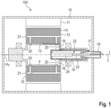
- Fig.1 shows in a schematic sectional view an electrical machine 100 comprising a housing 10, a stator 11 and a rotor 12, wherein the rotor 12 comprises a hollow rotor shaft 13.
- the hollow rotor shaft 13 carries a rotor laminated core 14.
- the hollow rotor shaft 13 has an interior 15, wherein a tube 16 connected to the hollow rotor shaft 13 in a rotationally fixed manner is arranged in the interior 15.
- the hollow rotor shaft 13 has an inlet 17 through which a cooling fluid can be supplied to the tube 16.
- the tube 16 has outlet openings 18 through which a cooling fluid supplied to the tube 16 can be guided into the interior 15 of the hollow rotor shaft 13.
- a feed nozzle 19 is provided, with which a cooling fluid can be fed to the inlet 17 of the hollow rotor shaft 13.
- the feed nozzle 19 is arranged fixed to the housing.
- the hollow rotor shaft 13 also has outlets 20 through which a cooling fluid fed to the interior 15 of the hollow rotor shaft 13 can exit the hollow rotor shaft 13 and enter internal channels 21 of the rotor core 14 for internal rotor cooling.
- the electrical machine also has a potential equalization device 22 with a potential equalization rod 23 and a contact element 24. The potential equalization device 22 is described below with reference to the Fig.2 explained in more detail.
- the potential equalization rod 23 is fixed to the housing and aligned along the axis of rotation 25 of the hollow rotor shaft 13 and projects through the inlet 17 into the tube 16.
- the potential equalization rod 23 is also guided axially through the feed nozzle 19.
- the contact element 24 is also aligned along the axis of rotation 25 and arranged inside the tube 16.
- the contact element 24 is electrically connected to the tube 16 on the side 26 facing away from the inlet 17.
- the contact element 24 and the potential equalization rod 23 are in electrically conductive contact with one another, which is designed as a sliding contact 27.
- the tube 16 is connected to the hollow rotor shaft 13 by means of a shaft-hub connection 28.
- the shaft-hub connection 28 is designed to be electrically conductive and is electrically conductively connected to a contact point 29 of the hollow rotor shaft 13.
- the tube 16 which can otherwise be made of plastic, has at least one electrically conductive region, for example an electrically conductive coating 30 or a conductor track, which establishes the electrical contact between the shaft-hub connection 28 and the contact element 24.
- the potential equalization rod 23 is in turn electrically connected to a contact point 32 of the housing 10 via an electrical conductor 31.
- a potential difference between the contact point 29 of the hollow rotor shaft 13 and the contact point 32 of the housing 10 can thus be equalized via the shaft-hub connection 28, the electrically conductive coating 30 of the tube 16, the contact element 24, the potential equalization rod 23 and the electrical conductor 31.
- a cooling fluid such as a cooling oil
- a cooling fluid can be fed through the inlet 17 of the hollow rotor shaft 13 into the tube 16 through the feed nozzle 19. Due to the central arrangement of the potential equalization rod 23 and the contact element 24, the supply of the cooling fluid is not adversely affected.
- a spring element 33 is provided in the feed nozzle 19, which applies a contact force to the potential equalization rod 23 against the contact element 24.
- the tube 16 has an end section 34 in which the outlet region 35 of the feed nozzle 19 is accommodated, forming a gap 36.
- the gap 36 is chosen to be so narrow that leakage of cooling fluid introduced into the tube 16 through the gap 36 is prevented.
- the end section 34 has a diameter 37 which is smaller than the diameter 38 of the rest of the tube 16. This further prevents backflow of cooling fluid through the gap 36.
- the side 26 of the tube 16 facing away from the inlet 17 is axially closed.
- the tube 16 has radial outlet openings 18 through which cooling fluid fed to the tube 16 from the feed nozzle 19 can reach the interior 15 of the hollow rotor shaft 13. The cooling fluid can then flow further to the outlets 20 of the hollow rotor shaft 13.
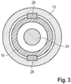
- Fig.3 shows a cross-sectional view of the hollow rotor shaft 13.
- the concentric arrangement of the hollow rotor shaft 13, tube 16 and contact element 24 is shown.
- the shaft-hub connection 28 is also shown.
Landscapes
- Engineering & Computer Science (AREA)
- Power Engineering (AREA)
- Motor Or Generator Cooling System (AREA)
Abstract
Um eine elektrische Maschine bereitzustellen, mit welcher ein elektrischer Potentialausgleich zwischen dem Rotor und dem Gehäuse der elektrischen Maschine erfolgen kann, ohne dass eine Kühlung des Rotors nachteilig beeinträchtigt wird, wird eine elektrische Maschine (100) umfassend ein Gehäuse (10), einen Stator (11) und einen Rotor (12) vorgeschlagen, wobei der Rotor (12) eine Rotorhohlwelle (13) mit einem Innenraum (15) umfasst, wobei im Innenraum (15) ein drehfest mit der Rotorhohlwelle (13) angeordnetes Rohr (16) angeordnet ist, wobei die Rotorhohlwelle (13) einen Einlass (17) aufweist, durch den dem Rohr (16) ein Kühlfluid zugeführt werden kann, und wobei eine Potentialausgleichsvorrichtung (22) vorgesehen ist, wobei ferner vorgesehen ist, dass die Potentialausgleichsvorrichtung (22) einen gehäusefest und entlang einer Rotationsachse (25) der Rotorhohlwelle (13) ausgerichtet angeordneten und durch den Einlass (17) in das Rohr (16) hineinragenden Potentialausgleichsstab (23) und ein entlang der Rotationsachse (25) in dem Rohr (16) angeordnetes und elektrisch leitend mit dem Rohr (16) verbundenes Kontaktelement (24) aufweist, und dass der Potentialausgleichsstab (23) in einem elektrisch leitenden Kontakt mit dem Kontaktelement (24) steht.
Description
- Die vorliegende Erfindung betrifft eine elektrische Maschine umfassend ein Gehäuse, einen Stator und einen Rotor, wobei der Rotor eine Rotorhohlwelle mit einem Innenraum umfasst, wobei im Innenraum ein drehfest mit der Rotorhohlwelle verbundenes Rohr angeordnet ist, wobei die Rotorhohlwelle einen Einlass aufweist, durch den dem Rohr ein Kühlfluid zugeführt werden kann, und wobei eine Potentialausgleichsvorrichtung vorgesehen ist.
- Im Betrieb von elektrischen Maschinen kann es zu Potentialdifferenzen zwischen dem Rotor und dem Gehäuse der elektrischen Maschine kommen. Um unerwünschte Spannungsentladungen zu vermeiden, ist es im Stand der Technik bekannt, mittels Potentialausgleichsvorrichtungen für einen elektrischen Potentialausgleich zwischen dem Rotor und dem Gehäuse zu sorgen.
- Die
DE 10 2020 208 518 A1 offenbart eine Anordnung für einen Elektromotor, aufweisend einen mittels einer Welle drehbar gelagerten Rotor und einen Stator, wobei die Welle als eine Hohlwelle ausgestaltet ist und radial durch mindestens ein Lager geführt ist, wobei an einem ersten axialen Endabschnitt der Welle eine Endkappe angeordnet ist, welche ein Innenvolumen der Welle axial endseitig begrenzt, wobei die Endkappe zumindest bereichsweise als ein Pumpenläufer geformt ist und Einlasskanäle zum Einleiten eines Kühlmittels in das Innenvolumen der Welle aufweist. Die Endkappe weist einen zentrierten Aufnahmeabschnitt zum Aufnehmen eines Kontaktelements auf, wobei das Kontaktelement durch ein mit dem Stator verbundenes Verbindungselement im zentrierten Aufnahmeabschnitt der Endkappe arretiert ist, oder wobei das Kontaktelement integral mit dem Verbindungselement oder integral mit der Endkappe ausgestaltet ist. Das Verbindungselement ist als eine Feder ausgestaltet und dazu eingerichtet, über das Kontaktelement eine elektrisch leitfähige Verbindung zwischen dem Rotor und dem Stator herzustellen. - Der vorliegenden Erfindung liegt die Aufgabe zugrunde, eine elektrische Maschine bereitzustellen, mit welcher ein elektrischer Potentialausgleich zwischen dem Rotor und dem Gehäuse der elektrischen Maschine erfolgen kann, ohne dass eine Kühlung des Rotors nachteilig beeinträchtigt wird.
- Zur Lösung der der Erfindung zugrundeliegenden Aufgabe wird eine elektrische Maschine umfassend ein Gehäuse, einen Stator und einen Rotor vorgeschlagen, wobei der Rotor eine Rotorhohlwelle mit einem Innenraum umfasst, wobei im Innenraum ein drehfest mit der Rotorhohlwelle verbundenes Rohr angeordnet ist, wobei die Rotorhohlwelle einen Einlass aufweist, durch den dem Rohr ein Kühlfluid zugeführt werden kann, und wobei eine Potentialausgleichsvorrichtung vorgesehen ist, wobei die Potentialausgleichsvorrichtung einen gehäusefest und entlang einer Rotationsachse der Rotorhohlwelle ausgerichtet angeordneten und durch den Einlass in das Rohr hineinragenden Potentialausgleichsstab und ein entlang der Rotationsachse in dem Rohr angeordnetes und elektrisch leitend mit dem Rohr verbundenes Kontaktelement aufweist, und wobei der Potentialausgleichsstab in einem elektrisch leitenden Kontakt mit dem Kontaktelement steht.
- Das Rohr kann mindestens eine Auslassöffnung aufweisen, durch die ein dem Rohr zugeführtes Kühlfluid in den Innenraum der Rotorhohlwelle geleitet werden kann. Der Stator und der Rotor sind im Inneren des Gehäuses der elektrischen Maschine angeordnet. Der Rotor weist bevorzugt ein Blechpaket auf, welches drehfest mit der Rotorhohlwelle verbunden ist. Im Rotorblechpaket können Innenkanäle für eine Rotorinnenkühlung vorgesehen sein. Die Rotorhohlwelle kann zudem, bevorzugt im Bereich ihrer axialen Enden, Auslässe aufweisen, durch die ein dem Innenraum der Rotorhohlwelle aus dem Rohr zugeführtes Kühlfluid aus der Rotorhohlwelle austreten und in die Innenkanäle des Rotorblechpaketes eintreten kann. Ein Kühlfluid kann somit durch den Einlass der Rotorhohlwelle zugeführt werden, sodass es in das in der Rotorhohlwelle drehfest angeordnete Rohr einströmt. Wenn in das Rohr durch den Einlass der Rotorhohlwelle ein Kühlfluid eingeführt wird, so wird dieses durch die Auslassöffnungen des Rohres in den Innenraum der Rotorhohlwelle geleitet und kann anschließend durch die Auslässe in die Innenkanäle des Rotorblechpaketes strömen. Bei dem Kühlfluid kann es sich insbesondere um ein Kühlöl handeln.
- Erfindungsgemäß weist die elektrische Maschine eine Potentialausgleichsvorrichtung auf, welche einen gehäusefest und entlang einer Rotationsachse der Rotorhohlwelle ausgerichtet angeordneten und durch den Einlass in das Rohr hineinragenden Potentialausgleichsstab und ein entlang der Rotationsachse in dem Rohr angeordnetes und elektrisch leitend mit dem Rohr verbundenes Kontaktelement aufweist, wobei der Potentialausgleichsstab in einem elektrisch leitenden Kontakt mit dem Kontaktelement steht. Sowohl der Potentialausgleichsstab als auch das Kontaktelement verlaufen somit zumindest teilweise im Inneren des Rohres beziehungsweise der Rotorhohlwelle und sind zentral entlang der Rotationsachse angeordnet. Wird der Rotorhohlwelle somit durch den Einlass ein Kühlfluid zugeführt, so wird aufgrund der zentralen Anordnung von Kontaktelement und Potentialausgleichsstab in dem Rohr die Kühlfluidströmung nicht nachteilig beeinträchtigt.
- Für den Potentialausgleich kann das Rohr direkt oder indirekt elektrisch leitend mit dem Rotor verbunden sein. Beispielsweise kann vorgesehen sein, dass das Rohr teilweise elektrisch leitend ist. So kann vorgesehen sein, dass das Rohr einen Kunststoff umfasst oder aus Kunststoff besteht, wobei in oder auf dem Rohr Leiterbahnen integriert sind. Ferner kann das Rohr zumindest teilweise mit einer elektrisch leitenden Beschichtung versehen sein. Eine zwischen dem Rotor und dem Gehäuse auftretende Potentialdifferenz kann vom Rotor über das Rohr, welches wie vorbeschrieben zumindest teilweise elektrisch leitend ist, das Kontaktelement und den Potentialausgleichsstab, welcher in einem elektrisch leitenden Kontakt mit dem Gehäuse steht, ausgeglichen werden.
- Besonders bevorzugt ist vorgesehen, dass der elektrisch leitende Kontakt zwischen Potentialausgleichsstab und Kontaktelement ein Schleifkontakt ist.
- Der Potentialausgleichsstab ist insbesondere drehfest mit dem Gehäuse verbunden, und das Kontaktelement ist drehfest mit dem Rohr verbunden. Das heißt, im Betrieb dreht sich das Kontaktelement mit der Rotorhohlwelle beziehungsweise dem Rohr mit, wohingegen der Potentialausgleichsstab sich nicht gegenüber dem Gehäuse dreht. Der elektrisch leitende Kontakt zwischen Potentialausgleichsstab und Kontaktelement ist daher bevorzugt als Schleifkontakt ausgebildet.
- Mit weiterem Vorteil kann vorgesehen sein, dass eine Zuführdüse vorgesehen ist, mit welcher ein Kühlfluid dem Einlass der Rotorhohlwelle zugeführt werden kann, und dass der Potentialausgleichsstab axial durch die Zuführdüse geführt ist.
- Der entlang der Rotationsachse des Rohres verlaufend ausgerichtete Potentialausgleichsstab kann somit aus dem Rohr hinaus axial durch die Zuführdüse geführt und im Inneren der Zuführdüse elektrisch leitend mit dem Gehäuse verbunden sein.
- Die Zufuhrdüse ist dabei bevorzugt gehäusefest angeordnet und ragt weiter bevorzugt in den Einlass der Rotorhohlwelle hinein. Die Zuführdüse kann darüber hinaus auch als Strahlapparat ausgebildet sein.
- Bevorzugt ist vorgesehen, dass die Zuführdüse entlang der Rotationsachse ausgerichtet ist.
- Mit weiterem Vorteil kann vorgesehen sein, dass das Kontaktelement mit einer dem Einlass abgewandten Seite des Rohrs verbunden ist.
- Mit anderen Worten durchläuft das Kontaktelement beziehungsweise die Kombination aus Kontaktelement und Potentialausgleichsstab bevorzugt das gesamte Rohr entlang der Rotationsachse bis zu der dem Einlass abgewandten Seite des Rohres. An der dem Einlass abgewandten Seite des Rohres ist das Kontaktelement elektrisch leitend mit dem Rohr verbunden.
- Mit weiterem Vorteil kann vorgesehen sein, dass das Rohr mit einer Welle-Nabe-Verbindung drehfest mit der Rotorhohlwelle verbunden ist, wobei die Welle-Nabe-Verbindung elektrisch leitend ausgebildet ist, und dass ein elektrischer Leiter die Welle-Nabe-Verbindung mit dem Kontaktelement verbindet.
- Die Welle-Nabe-Verbindung zwischen Rohr und Rotorhohlwelle erfüllt somit eine Doppelfunktion. Zum einen bewirkt die Welle-Nabe-Verbindung eine drehfeste Anordnung des Rohres in der Rotorhohlwelle. Gleichzeitig dient die Welle-Nabe-Verbindung der elektrisch leitenden Verbindung des Rotors mit dem Kontaktelement über das Rohr, beispielsweise über in oder auf dem Rohr vorgesehene Leiterbahnen oder über eine elektrisch leitende Beschichtung des Rohrs. Mit anderen Worten kann der elektrische Leiter als Leiterbahn oder als elektrisch leitende Beschichtung des Rohres ausgebildet sein.
- Bevorzugt kann vorgesehen sein, dass die Welle-Nabe-Verbindung elektrisch leitend mit einem Kontaktpunkt der Rotorhohlwelle verbunden ist, und dass der Potentialausgleichsstab elektrisch leitend mit einem Kontaktpunkt des Gehäuses verbunden ist.
- Die Rotorhohlwelle steht für den Potentialausgleich in einem elektrisch leitenden Kontakt mit dem Rotorblechpaket. Für diese elektrisch leitende Verbindung kann ein Kontaktpunkt an der Rotorhohlwelle vorgesehen sein. Über einen dazu vorgesehenen elektrischen Leiter ist der Kontaktpunkt der Rotorwohlwelle mit der Welle-Nabe-Verbindung verbunden. Die Welle-Nabe-Verbindung ist wiederum elektrisch leitend über das Rohr mit dem Kontaktelement verbunden. Über den elektrischen Kontakt zwischen Kontaktelement und Potentialausgleichsstab kann anschließend der Potentialausgleich des Rotors über einen Kontaktpunkt des Gehäuses erfolgen.
- Mit weiterem Vorteil kann vorgesehen sein, dass, bevorzugt in der Zuführdüse, ein Federelement vorgesehen ist, welches den Potentialausgleichsstab mit einer Kontaktkraft gegen das Kontaktelement beaufschlagt.
- Alternativ oder zusätzlich kann auch vorgesehen sein, dass der innerhalb der Zuführdüse im Betrieb aufgebaute Kühlfluiddruck den Potentialausgleichsstab mit einer Kontaktkraft gegen das Kontaktelement beaufschlagt.
- Mit weiterem Vorteil kann vorgesehen sein, dass ein Endabschnitt an der dem Einlass zugewandten Seite des Rohres vorgesehen ist, wobei ein Auslassbereich der Zuführdüse in dem Endabschnitt, bevorzugt unter Ausbildung eines Spaltes, aufgenommen ist, wobei ein Durchmesser des Rohres größer ist als ein Durchmesser des Endabschnitts, wobei bevorzugt der Auslassbereich durch den Endabschnitt in das Rohr hineinragend angeordnet ist.
- Der Endabschnitt des Rohres ist dabei bevorzugt jener Abschnitt, welcher im Bereich des Einlasses der Rotorhohlwelle angeordnet ist. Die Zuführdüse ragt durch den Endabschnitt hindurch und in das Rohr hinein. Der Endabschnitt weist einen geringeren Durchmesser als der Rest des Rohres auf. Diese Reduktion des Durchmessers dient dazu, die Gefahr einer Leckage durch den Spalt zu verringern. Hierbei kann zwischen dem Rohr und dem Endabschnitt eine Stufe oder ähnliches vorgesehen sein.
- Der Spalt zwischen der Zuführdüse und dem Endabschnitt ist dabei vorteilhafterweise so gering ausgebildet, dass die Gefahr einer Leckage weiter verringert wird. Der Endabschnitt kann bei einer Rotation der Rotorhohlwelle berührungsfrei um die Zuführdüse rotieren.
- Zudem kann vorgesehen sein, dass das Rohr an der dem Strahlapparat abgewandten Seite axial verschlossen ist, dass das Rohr mindestens eine Auslassöffnung aufweist, durch die ein dem Rohr zugeführtes Kühlfluid in den Innenraum der Rotorhohlwelle geleitet werden kann, wobei die mindestens eine Auslassöffnung in einer Außenwand des Rohres angeordnet ist, wobei bevorzugt die Auslassöffnung in einem Winkel gegenüber einer Radialrichtung geneigt ausgebildet ist.
- Das Kühlfluid tritt somit bevorzugt nicht axial aus dem Rohr in den Innenraum der Rotorhohlwelle aus, sondern wird radial durch Auslassöffnungen in der radialen Außenwand des Rohres in den Innenraum der Rotorhohlwelle geleitet. Bei der Außenwand kann es sich insbesondere um die radiale Umfangswand des Rohres handeln. Dabei ist ferner vorgesehen, dass die Auslassöffnungen in einem Winkel gegenüber einer Radialrichtung geneigt ausgebildet sind. Hierdurch kann aus den Auslassöffnungen austretendes Kühlfluid gerichtet in den Innenraum der Rotorhohlwelle einströmen, um eine symmetrische Verteilung des Kühlfluids in dem Innenraum der Rotorhohlwelle zu begünstigen.
- Die Erfindung wird nachstehend näher anhand der beigefügten Figuren erläutert. Es zeigen:
- Fig. 1
- eine elektrische Maschine mit einer Potentialausgleichsvorrichtung,
- Fig. 2
- eine Rotorhohlwelle mit einem Potentialausgleichsstab und einem Kontaktelement, und
- Fig. 3
- eine elektrisch leitende Welle-Nabe-Verbindung zwischen einer Rotorwelle und einem darin angeordneten Rohr.
-
Fig. 1 zeigt in einer schematischen Schnittansicht eine elektrische Maschine 100 umfassend ein Gehäuse 10, einen Stator 11 und einen Rotor 12, wobei der Rotor 12 eine Rotorhohlwelle 13 umfasst. Die Rotorhohlwelle 13 trägt ein Rotorblechpaket 14. Die Rotorhohlwelle 13 weist einen Innenraum 15 auf, wobei im Innenraum 15 ein drehfest mit der Rotorhohlwelle 13 verbundenes Rohr 16 angeordnet ist. Die Rotorhohlwelle 13 weist einen Einlass 17 auf, durch den dem Rohr 16 ein Kühlfluid zugeführt werden kann. Das Rohr 16 weist Auslassöffnungen 18 auf, durch die ein dem Rohr 16 zugeführtes Kühlfluid in den Innenraum 15 der Rotorhohlwelle 13 geleitet werden kann. Es ist eine Zuführdüse 19 vorgesehen, mit welcher ein Kühlfluid dem Einlass 17 der Rotorhohlwelle 13 zugeführt werden kann. Die Zuführdüse 19 ist gehäusefest angeordnet. Die Rotorhohlwelle 13 weist ferner Auslässe 20 auf, durch die ein dem Innenraum 15 der Rotorhohlwelle 13 zugeführtes Kühlfluid aus der Rotorhohlwelle 13 austreten und in Innenkanäle 21 des Rotorblechpaketes 14 zur Rotorinnenkühlung eintreten kann. Die elektrische Maschine weist darüber hinaus eine Potentialausgleichsvorrichtung 22 mit einem Potentialausgleichsstab 23 und einem Kontaktelement 24 auf. Die Potentialausgleichsvorrichtung 22 wird folgend bezugnehmend auf dieFig. 2 näher erläutert. - Der Potentialausgleichsstab 23 ist gehäusefest angeordnet und entlang der Rotationsachse 25 der Rotorhohlwelle 13 ausgerichtet und ragt durch den Einlass 17 in das Rohr 16 hinein. Dabei ist der Potentialausgleichsstab 23 auch axial durch die Zuführdüse 19 geführt. Das Kontaktelement 24 ist ebenfalls entlang der Rotationsachse 25 ausgerichtet und im Inneren des Rohrs 16 angeordnet. Das Kontaktelement 24 ist an der dem Einlass 17 abgewandten Seite 26 elektrisch leitend mit dem Rohr 16 verbunden. Das Kontaktelement 24 und der Potentialausgleichsstab 23 stehen in einem elektrisch leitenden Kontakt miteinander, welcher als Schleifkontakt 27 ausgebildet ist. Das Rohr 16 ist mittels einer Welle-Nabe-Verbindung 28 mit der Rotorhohlwelle 13 verbunden. Die Welle-Nabe-Verbindung 28 ist dabei elektrisch leitend ausgebildet und elektrisch leitend mit einem Kontaktpunkt 29 der Rotorhohlwelle 13 verbunden. Das Rohr 16, welches ansonsten aus Kunststoff gefertigt sein kann, weist zumindest einen elektrisch leitenden Bereich, zum Beispiel eine elektrisch leitende Beschichtung 30 oder eine Leiterbahn, auf, welche den elektrischen Kontakt zwischen der Welle-Nabe-Verbindung 28 und dem Kontaktelement 24 herstellt. Der Potentialausgleichsstab 23 ist wiederum über einen elektrischen Leiter 31 elektrisch leitend mit einem Kontaktpunkt 32 des Gehäuses 10 verbunden. Somit kann eine Potentialdifferenz zwischen dem Kontaktpunkt 29 der Rotorhohlwelle 13 und dem Kontaktpunkt 32 des Gehäuses 10 über die Welle-Nabe-Verbindung 28, die elektrisch leitende Beschichtung 30 des Rohres 16, das Kontaktelement 24, den Potentialausgleichsstab 23 und den elektrischen Leiter 31 ausgeglichen werden.
- Im Betrieb drehen sich das Rohr 16 und das Kontaktelement 24 mit der Rotorhohlwelle 13 mit, während der Potentialausgleichsstab 23 drehfest mit dem Gehäuse 10 verbunden ist. Durch die Zuführdüse 19 kann ein Kühlfluid, wie beispielsweise ein Kühlöl, durch den Einlass 17 der Rotorhohlwelle 13 in das Rohr 16 geleitet werden. Aufgrund der zentralen Anordnung von Potentialausgleichsstab 23 und Kontaktelement 24 wird die Zuführung des Kühlfluids nicht nachteilig beeinträchtigt. Zur Sicherstellung des elektrischen Schleifkontaktes 27 zwischen Potentialausgleichsstab 23 und Kontaktelement 24 ist ein Federelement 33 in der Zuführdüse 19 vorgesehen, welche den Potentialausgleichsstab 23 mit einer Kontaktkraft gegen das Kontaktelement 24 beaufschlagt.
- Die ebenfalls gehäusefest angeordnete Zuführdüse 19 ragt durch den Einlass 17 der Rotorhohlwelle 13 hinein. Das Rohr 16 weist einen Endabschnitt 34 auf, in welchem der Auslassbereich 35 der Zuführdüse 19 unter Ausbildung eines Spaltes 36 aufgenommen ist. Der Spalt 36 ist dabei so schmal gewählt, dass eine Leckage von in das Rohr 16 eingeführtem Kühlfluid durch den Spalt 36 verhindert wird. Ferner weist der Endabschnitt 34 einen Durchmesser 37 auf, welcher geringer als der Durchmesser 38 des restlichen Rohrs 16 ist. Hierdurch wird ein Rückfluss von Kühlfluid durch den Spalt 36 weiter verhindert. An der dem Einlass 17 abgewandten Seite 26 des Rohres 16 ist dieses axial verschlossen. Das Rohr 16 weist radiale Auslassöffnungen 18 auf, durch die ein dem Rohr 16 von der Zuführdüse 19 zugeführtes Kühlfluid in den Innenraum 15 der Rotorhohlwelle 13 gelangen kann. Das Kühlfluid kann anschließend weiter zu den Auslässen 20 der Rotorhohlwelle 13 strömen.
-
Fig. 3 zeigt eine Querschnittsansicht der Rotorhohlwelle 13. Gezeigt ist die konzentrische Anordnung von Rotorhohlwelle 13, Rohr 16 und Kontaktelement 24. Ferner ist die Welle-Nabe-Verbindung 28 gezeigt. -
- 100
- Elektrische Maschine
- 10
- Gehäuse
- 11
- Stator
- 12
- Rotor
- 13
- Rotorhohlwelle
- 14
- Rotorblechpaket
- 15
- Innenraum
- 16
- Rohr
- 17
- Einlass
- 18
- Auslassöffnung
- 19
- Zuführdüse
- 20
- Auslass
- 21
- Innenkanal
- 22
- Potentialausgleichsvorrichtung
- 23
- Potentialausgleichsstab
- 24
- Kontaktelement
- 25
- Rotationsachse
- 26
- Abgewandte Seite
- 27
- Schleifkontakt
- 28
- Welle-Nabe-Verbindung
- 29
- Kontaktpunkt
- 30
- Elektrisch leitende Beschichtung
- 31
- Elektrischer Leiter
- 32
- Kontaktpunkt
- 33
- Federelement
- 34
- Endabschnitt
- 35
- Auslassbereich
- 36
- Spalt
- 37
- Durchmesser
- 38
- Durchmesser
Claims (10)
- Elektrische Maschine (100) umfassend ein Gehäuse (10), einen Stator (11) und einen Rotor (12), wobei der Rotor (12) eine Rotorhohlwelle (13) mit einem Innenraum (15) umfasst, wobei im Innenraum (15) ein drehfest mit der Rotorhohlwelle (13) verbundenes Rohr (16) angeordnet ist, wobei die Rotorhohlwelle (13) einen Einlass (17) aufweist, durch den dem Rohr (16) ein Kühlfluid zugeführt werden kann, und wobei eine Potentialausgleichsvorrichtung (22) vorgesehen ist, dadurch gekennzeichnet, dass die Potentialausgleichsvorrichtung (22) einen gehäusefest und entlang einer Rotationsachse (25) der Rotorhohlwelle (13) ausgerichtet angeordneten und durch den Einlass (17) in das Rohr (16) hineinragenden Potentialausgleichsstab (23) und ein entlang der Rotationsachse (25) in dem Rohr (16) angeordnetes und elektrisch leitend mit dem Rohr (16) verbundenes Kontaktelement (24) aufweist, und dass der Potentialausgleichsstab (23) in einem elektrisch leitenden Kontakt mit dem Kontaktelement (24) steht.
- Elektrische Maschine (100) nach Anspruch 1, dadurch gekennzeichnet, dass der elektrisch leitende Kontakt zwischen Potentialausgleichsstab (23) und Kontaktelement (24) ein Schleifkontakt (27) ist.
- Elektrische Maschine (100) nach Anspruch 1 oder 2, dadurch gekennzeichnet, dass eine Zuführdüse (19) vorgesehen ist, mit welcher ein Kühlfluid dem Einlass (17) der Rotorhohlwelle (13) zugeführt werden kann, und dass der Potentialausgleichsstab (23) axial durch die Zuführdüse (19) geführt ist.
- Elektrische Maschine (100) nach Anspruch 3, dadurch gekennzeichnet, dass die Zuführdüse (19) entlang der Rotationsachse (25) ausgerichtet ist.
- Elektrische Maschine (100) nach einem der vorgenannten Ansprüche, dadurch gekennzeichnet, dass das Kontaktelement (24) mit einer dem Einlass (17) abgewandten Seite (26) des Rohrs (16) verbunden ist.
- Elektrische Maschine (100) nach einem der vorgenannten Ansprüche, dadurch gekennzeichnet, dass das Rohr (16) mit einer Welle-Nabe-Verbindung (28) drehfest mit der Rotorhohlwelle (13) verbunden ist, wobei die Welle-Nabe-Verbindung (28) elektrisch leitend ausgebildet ist, und dass ein elektrischer Leiter die Welle-Nabe-Verbindung (28) mit dem Kontaktelement (24) verbindet.
- Elektrische Maschine (100) nach Anspruch 6, dadurch gekennzeichnet, dass die Welle-Nabe-Verbindung (28) elektrisch leitend mit einem Kontaktpunkt (29) der Rotorhohlwelle (13) verbunden ist, und dass der Potentialausgleichsstab (23) elektrisch leitend mit einem Kontaktpunkt (32) des Gehäuses (10) verbunden ist.
- Elektrische Maschine (100) nach einem der vorgenannten Ansprüche, dadurch gekennzeichnet, dass, bevorzugt in der Zuführdüse (19), ein Federelement (33) vorgesehen ist, welches den Potentialausgleichsstab (23) mit einer Kontaktkraft gegen das Kontaktelement (24) beaufschlagt.
- Elektrische Maschine (100) nach einem der Ansprüche 3 bis 8, dadurch gekennzeichnet, dass ein Endabschnitt (34) an der dem Einlass (17) zugewandten Seite (26) des Rohrs (16) vorgesehen ist, wobei ein Auslassbereich (35) der Zuführdüse (19) in dem Endabschnitt (34), bevorzugt unter Ausbildung eines Spaltes (37), aufgenommen ist, wobei ein Durchmesser (38) des Rohrs (16) größer ist als ein Durchmesser (37) des Endabschnitts (34), wobei bevorzugt der Auslassbereich (35) durch den Endabschnitt (34) in das Rohr (16) hineinragend angeordnet ist.
- Elektrische Maschine (100) nach einem der vorgenannten Ansprüche, dadurch gekennzeichnet, dass das Rohr (16) an der dem Einlass (17) abgewandten Seite (26) axial verschlossen ist, dass das Rohr (16) mindestens eine Auslassöffnung (18) aufweist, durch die ein dem Rohr (16) zugeführtes Kühlfluid in den Innenraum (15) der Rotorhohlwelle (13) geleitet werden kann, wobei die mindestens eine Auslassöffnung (18) in einer Außenwand des Rohrs (16) angeordnet ist, wobei bevorzugt die Auslassöffnung (18) in einem Winkel gegenüber einer Radialrichtung geneigt ausgebildet ist.
Applications Claiming Priority (1)
| Application Number | Priority Date | Filing Date | Title |
|---|---|---|---|
| DE102023200317.1A DE102023200317A1 (de) | 2023-01-17 | 2023-01-17 | Elektrische Maschine mit Potentialausgleichsvorrichtung |
Publications (1)
| Publication Number | Publication Date |
|---|---|
| EP4404442A1 true EP4404442A1 (de) | 2024-07-24 |
Family
ID=89474908
Family Applications (1)
| Application Number | Title | Priority Date | Filing Date |
|---|---|---|---|
| EP24150537.9A Pending EP4404442A1 (de) | 2023-01-17 | 2024-01-05 | Elektrische maschine mit potentialausgleichsvorrichtung |
Country Status (2)
| Country | Link |
|---|---|
| EP (1) | EP4404442A1 (de) |
| DE (1) | DE102023200317A1 (de) |
Citations (3)
| Publication number | Priority date | Publication date | Assignee | Title |
|---|---|---|---|---|
| DE102020108834A1 (de) * | 2020-03-31 | 2021-09-30 | Schaeffler Technologies AG & Co. KG | Elektrische Antriebsanordnung für ein Fahrzeug |
| DE102020208518A1 (de) | 2020-07-07 | 2022-01-13 | Volkswagen Aktiengesellschaft | Wellenkühlung |
| CN217159498U (zh) * | 2022-02-15 | 2022-08-09 | 上海纳铁福传动系统有限公司 | 防止电机轴承电腐蚀的电刷装置及电机 |
Family Cites Families (4)
| Publication number | Priority date | Publication date | Assignee | Title |
|---|---|---|---|---|
| US9373984B2 (en) * | 2011-06-29 | 2016-06-21 | General Electric Company | Electrical machine |
| HUE060485T2 (hu) * | 2016-06-07 | 2023-03-28 | Tesla Inc | Villanymotor hûtési rendszer |
| US11002191B2 (en) * | 2019-01-04 | 2021-05-11 | Ge Aviation Systems Llc | Electric machine with non-contact interface |
| JP7604954B2 (ja) * | 2021-03-08 | 2024-12-24 | ニデック株式会社 | 回転電機、および駆動装置 |
-
2023
- 2023-01-17 DE DE102023200317.1A patent/DE102023200317A1/de active Pending
-
2024
- 2024-01-05 EP EP24150537.9A patent/EP4404442A1/de active Pending
Patent Citations (3)
| Publication number | Priority date | Publication date | Assignee | Title |
|---|---|---|---|---|
| DE102020108834A1 (de) * | 2020-03-31 | 2021-09-30 | Schaeffler Technologies AG & Co. KG | Elektrische Antriebsanordnung für ein Fahrzeug |
| DE102020208518A1 (de) | 2020-07-07 | 2022-01-13 | Volkswagen Aktiengesellschaft | Wellenkühlung |
| CN217159498U (zh) * | 2022-02-15 | 2022-08-09 | 上海纳铁福传动系统有限公司 | 防止电机轴承电腐蚀的电刷装置及电机 |
Also Published As
| Publication number | Publication date |
|---|---|
| DE102023200317A1 (de) | 2024-07-18 |
Similar Documents
| Publication | Publication Date | Title |
|---|---|---|
| EP1649575A1 (de) | Elektrische maschine mit läuferkühlung und entsprechendes kühlungsverfahren | |
| DE102016209173A1 (de) | Rotor für eine elektrische Maschine | |
| DE102019217510A1 (de) | Rotor, Elektromaschine und Kraftfahrzeug | |
| WO2021185542A1 (de) | Flüssigkeitsgekühlten rotor für einen elektromechanischen energiewandler | |
| DE102013020324A1 (de) | Elektrische Maschine, insbesondere Asynchronmaschine | |
| EP3739731A1 (de) | Führungsvorrichtung für ein wicklungsköpfe einer elektrischen maschine umfliessendes kühlfluid und elektrische maschine | |
| WO2024115011A1 (de) | Rotor und elektrische maschine | |
| DE102020007735A1 (de) | Ölsystem einer elektrischen Antriebseinheit | |
| DE102023200317A1 (de) | Elektrische Maschine mit Potentialausgleichsvorrichtung | |
| EP4437638A1 (de) | Rotoranordnung für eine elektrische maschine sowie elektrische maschine mit der rotoranordnung | |
| DE102020200197B4 (de) | Elektrische Maschine mit einem Leitelement | |
| DE102022003198A1 (de) | Elektrische Maschine, insbesondere für ein Kraftfahrzeug | |
| EP4639736A1 (de) | Elektrischer antrieb für ein elektrisch angetriebenes fahrzeug | |
| DE102023200316A1 (de) | Elektrische Maschine | |
| WO2023143656A1 (de) | Elektrische rotationsmaschine, elektrisches antriebssystem und getriebemotoreinheit | |
| WO2014000922A1 (de) | Bürstensystem für einen elektromotor und elektromotor mit solch einem bürstensystem | |
| DE102023002836B3 (de) | Elektrische Antriebsvorrichtung für ein Kraftfahrzeug, insbesondere für einen Kraftwagen | |
| DE102020007754A1 (de) | Elektrische Maschine | |
| WO2008107402A2 (de) | Rotierende elektrische maschine | |
| WO2024235628A1 (de) | Elektromotor mit wirkungsgradoptimiertem wickelkopf | |
| DE102024206275A1 (de) | Stator mit Kühlöffnungen, Elektromaschine und Kraftfahrzeug | |
| DE102022116208B4 (de) | Antriebseinrichtung für ein Kraftfahrzeug, insbesondere für einen Kraftwagen, sowie Kraftfahrzeug | |
| DE102024120518A1 (de) | Rotor für eine elektrische Maschine eines Kraftfahrzeugs sowie elektrische Maschine für ein Kraftfahrzeug | |
| DE102024111811A1 (de) | Lagersitzkörper für eine Rotorwelle einer elektrischen Maschine, Rotorwelle, Rotor, elektrische Maschine und Kraftfahrzeug | |
| DE102023202771A1 (de) | Anordnung zur Erdung einer Komponente |
Legal Events
| Date | Code | Title | Description |
|---|---|---|---|
| PUAI | Public reference made under article 153(3) epc to a published international application that has entered the european phase |
Free format text: ORIGINAL CODE: 0009012 |
|
| STAA | Information on the status of an ep patent application or granted ep patent |
Free format text: STATUS: THE APPLICATION HAS BEEN PUBLISHED |
|
| AK | Designated contracting states |
Kind code of ref document: A1 Designated state(s): AL AT BE BG CH CY CZ DE DK EE ES FI FR GB GR HR HU IE IS IT LI LT LU LV MC ME MK MT NL NO PL PT RO RS SE SI SK SM TR |
|
| STAA | Information on the status of an ep patent application or granted ep patent |
Free format text: STATUS: REQUEST FOR EXAMINATION WAS MADE |
|
| 17P | Request for examination filed |
Effective date: 20250124 |