EP4404426A1 - Battery device, battery management system, and pre-charge period configuration method - Google Patents
Battery device, battery management system, and pre-charge period configuration method Download PDFInfo
- Publication number
- EP4404426A1 EP4404426A1 EP22887368.3A EP22887368A EP4404426A1 EP 4404426 A1 EP4404426 A1 EP 4404426A1 EP 22887368 A EP22887368 A EP 22887368A EP 4404426 A1 EP4404426 A1 EP 4404426A1
- Authority
- EP
- European Patent Office
- Prior art keywords
- precharge
- voltage
- time
- connection terminal
- duration
- Prior art date
- Legal status (The legal status is an assumption and is not a legal conclusion. Google has not performed a legal analysis and makes no representation as to the accuracy of the status listed.)
- Granted
Links
Images


Classifications
-
- H—ELECTRICITY
- H01—ELECTRIC ELEMENTS
- H01M—PROCESSES OR MEANS, e.g. BATTERIES, FOR THE DIRECT CONVERSION OF CHEMICAL ENERGY INTO ELECTRICAL ENERGY
- H01M10/00—Secondary cells; Manufacture thereof
- H01M10/42—Methods or arrangements for servicing or maintenance of secondary cells or secondary half-cells
-
- H—ELECTRICITY
- H02—GENERATION; CONVERSION OR DISTRIBUTION OF ELECTRIC POWER
- H02J—ELECTRIC POWER NETWORKS; CIRCUIT ARRANGEMENTS OR SYSTEMS FOR SUPPLYING OR DISTRIBUTING ELECTRIC POWER; SYSTEMS FOR STORING ELECTRIC ENERGY
- H02J7/00—Circuit arrangements for charging or discharging batteries or for supplying loads from batteries
- H02J7/60—Circuit arrangements for charging or discharging batteries or for supplying loads from batteries including safety or protection arrangements
- H02J7/62—Circuit arrangements for charging or discharging batteries or for supplying loads from batteries including safety or protection arrangements against overcurrent
-
- H—ELECTRICITY
- H01—ELECTRIC ELEMENTS
- H01M—PROCESSES OR MEANS, e.g. BATTERIES, FOR THE DIRECT CONVERSION OF CHEMICAL ENERGY INTO ELECTRICAL ENERGY
- H01M10/00—Secondary cells; Manufacture thereof
- H01M10/42—Methods or arrangements for servicing or maintenance of secondary cells or secondary half-cells
- H01M10/44—Methods for charging or discharging
-
- H—ELECTRICITY
- H01—ELECTRIC ELEMENTS
- H01M—PROCESSES OR MEANS, e.g. BATTERIES, FOR THE DIRECT CONVERSION OF CHEMICAL ENERGY INTO ELECTRICAL ENERGY
- H01M10/00—Secondary cells; Manufacture thereof
- H01M10/42—Methods or arrangements for servicing or maintenance of secondary cells or secondary half-cells
- H01M10/48—Accumulators combined with arrangements for measuring, testing or indicating the condition of cells, e.g. the level or density of the electrolyte
-
- H—ELECTRICITY
- H02—GENERATION; CONVERSION OR DISTRIBUTION OF ELECTRIC POWER
- H02J—ELECTRIC POWER NETWORKS; CIRCUIT ARRANGEMENTS OR SYSTEMS FOR SUPPLYING OR DISTRIBUTING ELECTRIC POWER; SYSTEMS FOR STORING ELECTRIC ENERGY
- H02J7/00—Circuit arrangements for charging or discharging batteries or for supplying loads from batteries
- H02J7/34—Parallel operation in networks using both storage and other DC sources, e.g. providing buffering
- H02J7/345—Parallel operation in networks using both storage and other DC sources, e.g. providing buffering using capacitors as storage or buffering devices
-
- H—ELECTRICITY
- H02—GENERATION; CONVERSION OR DISTRIBUTION OF ELECTRIC POWER
- H02J—ELECTRIC POWER NETWORKS; CIRCUIT ARRANGEMENTS OR SYSTEMS FOR SUPPLYING OR DISTRIBUTING ELECTRIC POWER; SYSTEMS FOR STORING ELECTRIC ENERGY
- H02J7/00—Circuit arrangements for charging or discharging batteries or for supplying loads from batteries
- H02J7/60—Circuit arrangements for charging or discharging batteries or for supplying loads from batteries including safety or protection arrangements
- H02J7/663—Circuit arrangements for charging or discharging batteries or for supplying loads from batteries including safety or protection arrangements using battery or load disconnect circuits
-
- H—ELECTRICITY
- H02—GENERATION; CONVERSION OR DISTRIBUTION OF ELECTRIC POWER
- H02J—ELECTRIC POWER NETWORKS; CIRCUIT ARRANGEMENTS OR SYSTEMS FOR SUPPLYING OR DISTRIBUTING ELECTRIC POWER; SYSTEMS FOR STORING ELECTRIC ENERGY
- H02J7/00—Circuit arrangements for charging or discharging batteries or for supplying loads from batteries
- H02J7/80—Circuit arrangements for charging or discharging batteries or for supplying loads from batteries including monitoring or indicating arrangements
-
- H—ELECTRICITY
- H02—GENERATION; CONVERSION OR DISTRIBUTION OF ELECTRIC POWER
- H02J—ELECTRIC POWER NETWORKS; CIRCUIT ARRANGEMENTS OR SYSTEMS FOR SUPPLYING OR DISTRIBUTING ELECTRIC POWER; SYSTEMS FOR STORING ELECTRIC ENERGY
- H02J7/00—Circuit arrangements for charging or discharging batteries or for supplying loads from batteries
- H02J7/855—Circuit arrangements for charging or discharging batteries or for supplying loads from batteries with circuits adapted for supplying loads from the battery
-
- H—ELECTRICITY
- H02—GENERATION; CONVERSION OR DISTRIBUTION OF ELECTRIC POWER
- H02J—ELECTRIC POWER NETWORKS; CIRCUIT ARRANGEMENTS OR SYSTEMS FOR SUPPLYING OR DISTRIBUTING ELECTRIC POWER; SYSTEMS FOR STORING ELECTRIC ENERGY
- H02J7/00—Circuit arrangements for charging or discharging batteries or for supplying loads from batteries
- H02J7/865—Battery or charger load switching, e.g. concurrent charging and load supply
-
- H—ELECTRICITY
- H02—GENERATION; CONVERSION OR DISTRIBUTION OF ELECTRIC POWER
- H02J—ELECTRIC POWER NETWORKS; CIRCUIT ARRANGEMENTS OR SYSTEMS FOR SUPPLYING OR DISTRIBUTING ELECTRIC POWER; SYSTEMS FOR STORING ELECTRIC ENERGY
- H02J7/00—Circuit arrangements for charging or discharging batteries or for supplying loads from batteries
- H02J7/90—Regulation of charging or discharging current or voltage
- H02J7/96—Regulation of charging or discharging current or voltage in response to battery voltage
-
- H—ELECTRICITY
- H01—ELECTRIC ELEMENTS
- H01M—PROCESSES OR MEANS, e.g. BATTERIES, FOR THE DIRECT CONVERSION OF CHEMICAL ENERGY INTO ELECTRICAL ENERGY
- H01M10/00—Secondary cells; Manufacture thereof
- H01M10/42—Methods or arrangements for servicing or maintenance of secondary cells or secondary half-cells
- H01M10/425—Structural combination with electronic components, e.g. electronic circuits integrated to the outside of the casing
- H01M2010/4271—Battery management systems including electronic circuits, e.g. control of current or voltage to keep battery in healthy state, cell balancing
-
- Y—GENERAL TAGGING OF NEW TECHNOLOGICAL DEVELOPMENTS; GENERAL TAGGING OF CROSS-SECTIONAL TECHNOLOGIES SPANNING OVER SEVERAL SECTIONS OF THE IPC; TECHNICAL SUBJECTS COVERED BY FORMER USPC CROSS-REFERENCE ART COLLECTIONS [XRACs] AND DIGESTS
- Y02—TECHNOLOGIES OR APPLICATIONS FOR MITIGATION OR ADAPTATION AGAINST CLIMATE CHANGE
- Y02E—REDUCTION OF GREENHOUSE GAS [GHG] EMISSIONS, RELATED TO ENERGY GENERATION, TRANSMISSION OR DISTRIBUTION
- Y02E60/00—Enabling technologies; Technologies with a potential or indirect contribution to GHG emissions mitigation
- Y02E60/10—Energy storage using batteries
Definitions
- the disclosure relates to a battery device, a battery management system, and a precharge duration setting method.
- Electric vehicles and hybrid vehicles are vehicles obtaining power by mainly using batteries as power sources for driving motors, and are alternatives capable of solving pollution and energy problems of internal combustion vehicles. For this reason, research has been actively carried out on them. Further, rechargeable batteries have been used in vehicles and even in various other external apparatuses.
- battery packs including a plurality of battery cells connected in series or parallel have been used. Furthermore, the potential risk of battery packs has increased as their power and capacity have increased. Particularly, when an overcurrent flows in a battery pack, if the overcurrent is not diagnosed, due to the overcurrent, problems may occur in external devices.
- Precharge circuits can prevent rush current by first charging capacitors connected to inverters and so on of external devices through precharge resistors in the initial stage of driving. By the way, if the time that it takes to precharge a capacitor is not sufficient, a main switch may be closed in the state where the capacitor has not been charged to a sufficient voltage. In this case, the main switch may be damaged due to the difference between the voltage of the battery pack and the voltage of the capacitor.
- the present disclosure has been made in an effort to provide a battery device, a battery management system, and a precharge duration setting method having merits of being capable of minimizing damage to a main switch.
- An embodiment provides a battery device including a positive connection terminal and a negative connection terminal which are connected to an external device.
- the battery device may include a battery pack, a positive main switch, a precharge switch, and a processor.
- the positive main switch may be connected between the positive terminal of the battery pack and the positive connection terminal.
- the precharge switch may be connected between the positive terminal of the battery pack and the positive connection terminal, and control the precharge operation of a capacitor of the external device.
- the processor may estimate a target time of a precharge duration in each of a plurality of cycles, and set the time of a precharge duration of the next cycle of the plurality of cycles, on the basis of the target times estimated respectively in the plurality of cycles.
- the processor may set the maximum value of the target times estimated respectively in the plurality of cycles, as the time of the precharge duration of the next cycle.
- the processor may perform precharge by closing the precharge switch during the precharge duration, and close the positive main switch after the precharge duration, and estimate the target time on the basis of a first voltage of the positive connection terminal immediately before closing the positive main switch and a second voltage of the positive connection terminal immediately after closing the positive main switch.
- the battery device may further include a precharge resistor that is connected between the positive terminal and the positive connection terminal when the precharge switch is closed.
- the precharge switch and the precharge resistor may be connected in series.
- the processor may estimate a time constant that is defined by the resistance value of the precharge resistor and the capacitance of the capacitor, on the basis of the first voltage and the second voltage, and estimate a predetermined multiple of the time constant as the target time.
- the predetermined multiple may be 5 times the time constant.
- the processor may set the time of the precharge duration of the corresponding cycle on the basis of the time taken for the voltage of the positive connection terminal to reach a predetermined voltage in the precharge duration.
- the predetermined voltage may be a voltage corresponding to a predetermined ratio to the voltage of the battery pack.
- the predetermined ratio may be determined on the basis of the predetermined multiple of the time constant defined by the resistance value of the precharge resistor and the capacitance of the capacitor.
- the processor may estimate the time constant on the basis of the time taken for the voltage of the positive connection terminal to reach the predetermined voltage during the precharge duration, and set the predetermined multiple of the time constant as the time of the precharge duration of the corresponding cycle.
- the predetermined multiple may be 6 times the time constant.
- the precharge duration setting method may include a step of performing a precharge operation of precharging a capacitor connected to the positive connection terminal and the negative connection terminal through a precharge resistor during the precharge duration of each of a plurality of cycles, a step of estimating a target time of the precharge duration in each of the plurality of cycles, and a step of setting the time of the precharge duration of the next cycle of the plurality of cycles, on the basis of the target times estimated in the plurality of cycles, respectively.
- the step of setting the time of the precharge duration may include a step of setting the maximum value of the target times estimated respectively in the plurality of cycles, as the time of the precharge duration of the next cycle.
- the step of estimating the target time may include a step of applying the voltage of the battery pack to the positive connection terminal after performing the precharge operation, a step of measuring the voltage of the positive connection terminal as a first voltage immediately before applying the voltage of the battery pack, a step of measuring the voltage of the positive connection terminal as a second voltage immediately after applying the voltage of the battery pack, and a step of estimating the target time on the basis of the first voltage and the second voltage.
- the step of estimating the target time on the basis of the first voltage and the second voltage may include a step of estimating a time constant that is defined by the resistance value of the precharge resistor and the capacitance of the capacitor, on the basis of the first voltage and the second voltage, and a step of estimating a predetermined multiple of the time constant as the target time.
- the battery management system may include a positive main switch, a precharge switch, and a processor.
- the positive main switch may be connected between the positive terminal of the battery pack and the positive connection terminal.
- the precharge switch may be connected between the positive terminal of the battery pack and the positive connection terminal, and control the precharge operation of a capacitor of the external device.
- the processor may estimate a target time of a precharge duration in each of a plurality of cycles, and set the time of a precharge duration of the next cycle of the plurality of cycles, on the basis of the target times estimated respectively in the plurality of cycles.
- constituent element when referred to as being “connected” to another constituent element, it may be directly connected to the other constituent element, or other constituent elements may be present between them. In contrast, it should be understood that when a constituent element is referred to as being “directly connected” to another constituent element, there is no other constituent element between them.
- FIG. 1 is a drawing illustrating a battery device according to an embodiment
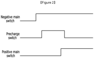
- FIG. 2 is a drawing illustrating switching timings in the battery device according to the embodiment.
- a battery device 100 has such a structure that it can be electrically connected to an external device 10 through a positive connection terminal DC(+) and a negative connection terminal DC(-).
- the battery device 100 operates as a power source for supplying power to the load, thereby being discharged.
- the external device 10 operating as a load may be, for example, an electronic apparatus, a transportation means, or an energy storage system (ESS), and the transportation means may be, for example, an electric vehicle, a hybrid vehicle, or smart mobility.
- ESS energy storage system
- the battery device 100 includes a battery pack 110, a switch circuit, a precharge circuit, a sensing circuit 140, and a processor 150.
- the battery pack 110 includes a plurality of battery cells (not shown in the drawings), and has a positive terminal PV(+) and a negative terminal PV(-).
- the battery cells may be secondary batteries which are rechargeable.
- a predetermined number of battery cells may be connected in series to constitute a battery module, and supply desired power.
- a predetermined number of battery modules may be connected in series or in parallel, and supply desired power.
- the switch circuit includes a positive main switch 121 connected between the positive terminal PV(+) of the battery pack 110 and the positive connection terminal DC(+) of the battery device 100, and a negative main switch 122 connected between the negative terminal PV(-) of the battery pack 110 and the negative connection terminal DC(-) of the battery device 100.
- each of the switches 121 and 122 may be a contactor composed of a relay.
- each of the switches 121 and 122 may be an electric switch such as a transistor.
- the switch circuit may further include driver circuits (not shown in the drawings) which control the switches 121 and 122, respectively.
- the precharge circuit is connected between the positive terminal PV(+) of the battery pack 110 and the positive connection terminal DC(+) of the battery device 100, and can first charge a capacitor 11 of the external device 10 which is connected to the connection terminals DC(+) and DC(-) during a precharge duration.
- the precharge circuit may include a precharge resistor 131 and a precharge switch 132. In the case where the precharge switch 132 is closed, the precharge resistor 131 can be connected between the positive terminal PV(+) of the battery pack 110 and the positive connection terminal DC(+) of the battery device 100. Accordingly, the precharge circuit can first charge the capacitor 11 of the external device 10 through the precharge resistor 131.
- the precharge resistor 131 and the precharge switch 132 may be connected in series between the positive terminal PV(+) of the battery pack 110 and the positive connection terminal DC(+) of the battery device 100.
- the precharge switch 132 may be a contactor composed of a relay.
- the precharge switch 132 may be an electric switch such as a transistor.
- the precharge circuit may further include a driver circuit (not shown in the drawings) which controls the precharge switch 132.
- the sensing circuit 140 senses the voltage on a predetermined point in the battery device 100.
- the sensing circuit 140 may sense the voltage of the positive connection terminal DC(+) of the battery device 100.
- the sensing circuit 140 may include a plurality of resistors (not shown in the drawings) connected in series between the positive connection terminal DC(+) and a ground terminal. In this case, the sensing circuit 140 may sense a voltage obtained by dividing the voltage of the positive connection terminal DC(+) by the plurality of resistors, as the voltage of the positive connection terminal DC(+).
- the sensing circuit 140 may further include an analog-to-digital converter which converts the voltage obtained by the voltage division using the plurality of resistors into a digital signal, and transmits the digital signal to the processor 150.
- the processor 150 may control the operations of the switches 121, 122, and 132. Further, the processor 150 may set a precharge duration on the basis of the voltage sensed by the sensing circuit 140. In some embodiments, the processor 150 may diagnose the capacitance of the capacitor 11 on the basis of the voltage sensed by the sensing circuit 140. In some embodiments, the processor 150 may be, for example, a micro controller unit (MCU).
- MCU micro controller unit
- the sensing circuit 140 and the processor 150 may be included in a battery management system (BMS) of the battery device.
- BMS battery management system
- the processor 150 first closes the negative main switch 122.
- the processor 150 closes the precharge switch 132 in the state where the negative main switch 122 is closed. Accordingly, precharge current can be supplied to the capacitor 11 of the external device 10 through the precharge resistor 131, whereby the capacitor 11 can be charged.
- the duration when the precharge switch 132 is closed, whereby the capacitor 11 is charged may be referred to as a precharge duration.
- the processor 150 closes the positive main switch 121 in order to transmit the voltage of the battery pack 110 to the external device 10.
- the processor 150 can open the precharge switch 132. Therefore, it is possible to prevent rush current from occurring when the voltage of the battery pack 110 is supplied to the external device 10 by the voltage to which the capacitor 11 of the external device 10 has been charged. Closing a switch may be referred to as turning on the switch, and opening a switch may be referred to as turning off the switch.
- precharge duration setting methods will be described with reference to FIG. 3 to FIG. 6 .
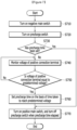
- FIG. 3 is a flow chart illustrating an example of a precharge duration setting method of a battery device according to an embodiment
- FIG. 4 is a drawing illustrating an example of an equivalent circuit of a battery device according to an embodiment during a precharge duration
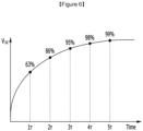
- FIG. 5 is a drawing illustrating an example of the voltage of a positive connection terminal in a battery device according to an embodiment
- FIG. 6 is a drawing illustrating voltage ratios depending on multiples of a time constant.
- the processor (for example, 150 in FIG. 1 ) of the battery device closes the negative main switch (for example, 122 in FIG. 1 ) (S310), and closes the precharge switch (for example, 132 in FIG. 1 ) (S320). Accordingly, a precharge duration starts, and the capacitor of the external device (for example, 11 in FIG. 1 ) can be charged.
- the processor 150 After performing the precharge operation (for example, when the precharge duration ends), the processor 150 closes the positive main switch (for example, 121 in FIG. 1 ) (S340).
- the processor 150 may apply the voltage of the battery pack 110 to the positive connection terminal DC(+) by closing the positive main switch 121.
- the processor 150 measures the voltage of the positive connection terminal (for example, DC(+)) of the battery device sensed by the sensing circuit (for example, 140 in FIG. 1 ) (S330).
- the processor 150 immediately after closing the positive main switch 121 (for example, immediately after applying the voltage of the battery pack 110 to the positive connection terminal DC(+)), the processor 150 measures the voltage of the positive connection terminal (DC(+)) of the battery device sensed by the sensing circuit 140 (S350). In some embodiments, after closing the positive main switch 121, the processor 150 may open the precharge switch 132 (S340).
- the processor 150 estimates a target time of the precharge duration (hereinafter, referred to as a "target precharge time"), on the basis of the voltage of the positive connection terminal (DC(+)) of the battery device measured immediately before it closed the positive main switch 121 and the voltage of the positive connection terminal (DC(+)) of the battery device measured immediately after it closed the positive main switch 121 (S360).
- the processor 150 may store the estimated target precharge time as the target precharge time of the current cycle.
- the processor 150 sets the time of the precharge duration (hereinafter, referred to as the "precharge time") of the next cycle, on the basis of the target precharge time (S370, S380).
- the processor may set the precharge time of the next cycle, on the basis of the target precharge times of a plurality of cycles.
- the processor 150 may determine whether each of the target precharge times of a predetermined number of cycles has been estimated (S370). In the case where the target precharge times of the predetermined number of cycles have not been estimated (S370), the processor 150 may repeat the procedure from S310 when the next cycle starts.
- the processor 150 may set the precharge time of the next cycle, on the basis of the target precharge times estimated in the predetermined number of cycles (S380). In some embodiments, the processor 150 may set the maximum value of the target precharge times estimated in the predetermined number of cycles, as the precharge time of the next cycle (S380). In some embodiments, the predetermined number may be 5.
- an RC equivalent circuit may be formed by the battery pack 110, the precharge resistor 131, and the capacitor 11. Then, the voltage of the capacitor 11, that is, the voltage V DC of the positive connection terminal DC(+) increases on the basis of the time constant ⁇ of an RC equivalent circuit 410, as shown in FIG. 5 .
- the voltage V DC of the capacitor 11 may vary, for example, as Equation 1.
- Equation 1 the time constant ⁇ is defined as the product of the resistance value R P of the precharge resistor 131 and the capacitance C EX of the capacitor 11.
- the processor 150 may estimate the time constant on the basis of the voltage V DC of the positive connection terminal DC(+) measured immediately before the positive main switch 121 was closed (the voltage of the capacitor 11 measured when the precharge duration ended), and the voltage V BAT of the positive connection terminal DC(+) (the voltage of the battery pack 110) measured immediately after the positive main switch 121 was closed.
- the time constant ⁇ can be calculated from Equation 1 by setting the voltage of the positive connection terminal DC(+) measured immediately before the positive main switch 121 was closed, the voltage of the positive connection terminal DC(+) measured immediately after the positive main switch 121 was closed, and the precharge duration of the current cycle as V DC , V BAT , and t, respectively.
- the processor 150 may set a target precharge time on the basis of the time constant ⁇ .
- the processor 150 may set n times the time constant as the target precharge time (wherein n is a positive real number). As shown in FIG. 6 , in the equivalent circuit shown in FIG.
- the voltage V DC of the capacitor 11 at 1 times the time constant ( ⁇ ) corresponds to 63% of the voltage V BAT of the battery pack 110
- the voltage V DC of the capacitor 11 at 2 times the time constant (2 ⁇ ) corresponds to 86% of the voltage V BAT of the battery pack 110
- the voltage V DC of the capacitor 11 at 3 times the time constant (3 ⁇ ) corresponds to 95% of the voltage V BAT of the battery pack 110
- the voltage V DC of the capacitor 11 at 4 times the time constant (4 ⁇ ) corresponds to 98% of the voltage V BAT of the battery pack 110
- the voltage V DC of the capacitor 11 at 5 times the time constant (5 ⁇ ) corresponds to 99% of the voltage V BAT of the battery pack 110.
- the processor 150 may set 5 times the time constant (5 ⁇ ) at which the voltage V DC of the capacitor 11 becomes 99% of the voltage V BAT of the battery pack 110, as the target precharge time.
- the processor 150 may set 5 times the time constant (5 ⁇ ) as the target precharge time, since the positive main switch 121 is closed when the voltage V DC of the positive connection terminal DC(+) reaches 99% of the voltage V BAT of the battery pack 110, damage to the positive main switch 121 can be minimized.
- the maximum value of target precharge times of a plurality of cycles it is possible to select such a time that damage to the positive main switch 121 can be minimized, in consideration of the deviation of measurements in the plurality of cycles.
- the precharge time is set on the basis of the target precharge times estimated in the predetermined number of cycles. Therefore, it is possible to set an accurate precharge time. In this case, even if the capacitance of the capacitor varies, the precharge time can be adaptively set. Further, since the voltage of the positive connection terminal DC(+) is measured immediately before the positive main switch 121 is closed and immediately after the positive main switch 121 is closed, it is possible to minimize the difference between the two voltage measurement time points. In other words, since the two voltage measurements are performed in substantially the same environment, it is possible to minimize errors in elements related to voltage measurement, thereby accurately estimating the time constant.
- the processor 150 may set a precharge time in the next cycle, on the basis of the target precharge times estimated in the predetermined number of cycles, respectively. Therefore, the precharge time of the current cycle may be set on the basis of the target precharge times estimated in the predetermined number of previous cycles, respectively.
- the precharge time of the i-th cycle may be set on the basis of the target precharge times estimated in the (i-5)-th to (i-1)-th cycles, respectively.
- the target precharge times of the predetermined number of previous cycles required to set the precharge time of the current cycle are not stored. For example, in the first cycle, since no previous cycle has been performed, target precharge times of previous cycles may not exist. Further, even in the second to fifth cycles, since the predetermined number of previous cycles have not been performed, target precharge times of the predetermined number of previous cycles may not exist. In this case, the precharge time of the current cycle may not be set.
- FIG. 7 is a flow chart illustrating an example of a method of setting an initial value of a precharge time in a battery device according to another embodiment.
- the processor of the battery device closes the negative main switch (for example, reference numeral 122 in FIG. 1 ) (S710), and closes the precharge switch (for example, reference numeral 132 in FIG. 1 ) (S720). Accordingly, a precharge duration starts, and the capacitor of the external device (for example, reference numeral 11 in FIG. 1 ) can be charged.
- the processor 150 may activate a timer to measure the elapsed time of the precharge duration. For example, the processor 150 may activate the timer when closing the precharge switch 132.
- the processor 150 determines whether the precharge time of the current cycle has been set (S730). In some embodiments, the processor 150 may determine whether the precharge time of the current cycle has been set, on the basis of the target precharge times of the predetermined number of previous cycles (S730). In some embodiments, the processor 150 may compare the number of previous cycles in which target precharge times have been estimated, with the predetermined number (S730).
- the processor 150 monitors the voltage V DC of the positive connection terminal (for example, DC(+)) of the battery device through the sensing circuit (for example, 140 in FIG. 1 ) (S740). While monitoring the voltage V DC of the positive connection terminal DC(+), the processor 150 compares the voltage of the positive connection terminal DC(+) with a predetermined voltage (S750).
- the predetermined voltage is a voltage determined on the basis of the voltage V BAT of the battery pack (for example, 110 in FIG. 1 ).
- the sensing circuit 140 may sense the voltage of the positive terminal PV(+) of the battery pack 110, whereby the processor 150 may measure the voltage V BAT of the battery pack 110.
- the predetermined voltage may be set on the basis of the voltage V BAT of the battery pack 110 and m times the time constant (wherein m is a positive real number). In some embodiments, the predetermined voltage may be set such that the ratio of the predetermined voltage to the voltage V BAT of the battery pack 110 is equal to the ratio of the voltage of the capacitor 11 to the voltage V BAT of the battery pack 110 that is obtained in the equivalent circuit shown in FIG. 4 when the precharge time corresponding to m times the time constant elapses. For example, as the predetermined voltage, 86% of the voltage V BAT of the battery pack 110, that is, 0.86V BAT may be set on the basis of 2 times the time constant.
- the processor 150 sets the precharge time (initial precharge time) of the current cycle on the basis of the time taken for the voltage of the positive connection terminal DC(+) to reach the predetermined voltage (S760).
- the processor 150 may set the initial precharge time on the basis of the time taken for the voltage V BAT of the battery pack 110 to reach the predetermined voltage and m times the time constant used to set the predetermined voltage (S760).
- the processor 150 may set k times the time taken for the voltage V BAT of the battery pack 110 to reach the predetermined voltage, as the initial precharge time (wherein k is a positive real number).
- the initial precharge time may be set to (k*m) times the time constant.
- (k*m) may be set to be larger than n times the time constant used to set the above-described target precharge time.
- the initial precharge time is set to be long. Therefore, it is possible to minimize damage to the positive main switch (for example, 121 in FIG. 1 ) attributable to errors in voltage measurement.
- the processor 150 closes the positive main switch 121 (S770).
- the processor 150 closes the positive main switch 121 (S770). Accordingly, the precharge duration ends.
- the processor 150 may open the precharge switch 132 after closing the positive main switch 121 (S770).
- the processor 150 may measure the voltage of the positive connection terminal DC(+) of the battery device immediately before closing the positive main switch 121 as described with reference to FIG. 3 , and measure the voltage of the positive connection terminal DC(+) of the battery device immediately after closing the positive main switch 121.
- the processor 150 may estimate the target precharge time of the current cycle on the basis of the voltage of the positive connection terminal DC(+) of the battery device measured immediately before it closed the positive main switch 121 and the voltage of the positive connection terminal DC(+) of the battery device measured immediately after it closed the positive main switch 121.
- an initial precharge time can be set.
Landscapes
- Engineering & Computer Science (AREA)
- Power Engineering (AREA)
- Manufacturing & Machinery (AREA)
- Chemical & Material Sciences (AREA)
- Chemical Kinetics & Catalysis (AREA)
- Electrochemistry (AREA)
- General Chemical & Material Sciences (AREA)
- Secondary Cells (AREA)
- Charge And Discharge Circuits For Batteries Or The Like (AREA)
- Protection Of Static Devices (AREA)
- Emergency Protection Circuit Devices (AREA)
Abstract
Description
- This application claims priority to and the benefit of
Korean Patent Application No. 10-2021-0147896 filed in the Korean Intellectual Property Office on November 1, 2021 - The disclosure relates to a battery device, a battery management system, and a precharge duration setting method.
- Electric vehicles and hybrid vehicles are vehicles obtaining power by mainly using batteries as power sources for driving motors, and are alternatives capable of solving pollution and energy problems of internal combustion vehicles. For this reason, research has been actively carried out on them. Further, rechargeable batteries have been used in vehicles and even in various other external apparatuses.
- Recently, as high-power high-capacity batteries have been needed, battery packs including a plurality of battery cells connected in series or parallel have been used. Furthermore, the potential risk of battery packs has increased as their power and capacity have increased. Particularly, when an overcurrent flows in a battery pack, if the overcurrent is not diagnosed, due to the overcurrent, problems may occur in external devices.
- In order to prevent rush current of such overcurrent which is generated in the initial stage of driving, precharge circuits have been used. Precharge circuits can prevent rush current by first charging capacitors connected to inverters and so on of external devices through precharge resistors in the initial stage of driving. By the way, if the time that it takes to precharge a capacitor is not sufficient, a main switch may be closed in the state where the capacitor has not been charged to a sufficient voltage. In this case, the main switch may be damaged due to the difference between the voltage of the battery pack and the voltage of the capacitor.
- The present disclosure has been made in an effort to provide a battery device, a battery management system, and a precharge duration setting method having merits of being capable of minimizing damage to a main switch.
- An embodiment provides a battery device including a positive connection terminal and a negative connection terminal which are connected to an external device. The battery device may include a battery pack, a positive main switch, a precharge switch, and a processor. The positive main switch may be connected between the positive terminal of the battery pack and the positive connection terminal. The precharge switch may be connected between the positive terminal of the battery pack and the positive connection terminal, and control the precharge operation of a capacitor of the external device. The processor may estimate a target time of a precharge duration in each of a plurality of cycles, and set the time of a precharge duration of the next cycle of the plurality of cycles, on the basis of the target times estimated respectively in the plurality of cycles.
- In some embodiments, the processor may set the maximum value of the target times estimated respectively in the plurality of cycles, as the time of the precharge duration of the next cycle.
- In some embodiments, in each cycle, the processor may perform precharge by closing the precharge switch during the precharge duration, and close the positive main switch after the precharge duration, and estimate the target time on the basis of a first voltage of the positive connection terminal immediately before closing the positive main switch and a second voltage of the positive connection terminal immediately after closing the positive main switch.
- In some embodiments, the battery device may further include a precharge resistor that is connected between the positive terminal and the positive connection terminal when the precharge switch is closed.
- In some embodiments, the precharge switch and the precharge resistor may be connected in series.
- In some embodiments, the processor may estimate a time constant that is defined by the resistance value of the precharge resistor and the capacitance of the capacitor, on the basis of the first voltage and the second voltage, and estimate a predetermined multiple of the time constant as the target time.
- In some embodiments, the predetermined multiple may be 5 times the time constant.
- In some embodiments, in a cycle in which the time of the precharge duration has not been set, the processor may set the time of the precharge duration of the corresponding cycle on the basis of the time taken for the voltage of the positive connection terminal to reach a predetermined voltage in the precharge duration.
- In some embodiments, the predetermined voltage may be a voltage corresponding to a predetermined ratio to the voltage of the battery pack.
- In some embodiments, the predetermined ratio may be determined on the basis of the predetermined multiple of the time constant defined by the resistance value of the precharge resistor and the capacitance of the capacitor.
- In some embodiments, in a cycle in which the time of the precharge duration has not been set, the processor may estimate the time constant on the basis of the time taken for the voltage of the positive connection terminal to reach the predetermined voltage during the precharge duration, and set the predetermined multiple of the time constant as the time of the precharge duration of the corresponding cycle.
- In some embodiments, the predetermined multiple may be 6 times the time constant.
- Another embodiment provides a precharge duration setting method of a battery device including a battery pack, and a positive connection terminal and a negative connection terminal to be connected to an external device. The precharge duration setting method may include a step of performing a precharge operation of precharging a capacitor connected to the positive connection terminal and the negative connection terminal through a precharge resistor during the precharge duration of each of a plurality of cycles, a step of estimating a target time of the precharge duration in each of the plurality of cycles, and a step of setting the time of the precharge duration of the next cycle of the plurality of cycles, on the basis of the target times estimated in the plurality of cycles, respectively.
- In some embodiments, the step of setting the time of the precharge duration may include a step of setting the maximum value of the target times estimated respectively in the plurality of cycles, as the time of the precharge duration of the next cycle.
- In some embodiments, the step of estimating the target time may include a step of applying the voltage of the battery pack to the positive connection terminal after performing the precharge operation, a step of measuring the voltage of the positive connection terminal as a first voltage immediately before applying the voltage of the battery pack, a step of measuring the voltage of the positive connection terminal as a second voltage immediately after applying the voltage of the battery pack, and a step of estimating the target time on the basis of the first voltage and the second voltage.
- In some embodiments, the step of estimating the target time on the basis of the first voltage and the second voltage may include a step of estimating a time constant that is defined by the resistance value of the precharge resistor and the capacitance of the capacitor, on the basis of the first voltage and the second voltage, and a step of estimating a predetermined multiple of the time constant as the target time.
- In some embodiments, the precharge duration setting method may be a precharge duration setting method further including a step of setting the time of the precharge duration of a cycle in which the time of the precharge duration has not been set, on the basis of the time taken for the voltage of the positive connection terminal to reach a predetermined voltage, during the precharge duration of the corresponding cycle.
- Yet another embodiment provides a battery management system of a battery device including a battery pack, and a positive connection terminal and a negative connection terminal to be connected to an external device. The battery management system may include a positive main switch, a precharge switch, and a processor. The positive main switch may be connected between the positive terminal of the battery pack and the positive connection terminal. The precharge switch may be connected between the positive terminal of the battery pack and the positive connection terminal, and control the precharge operation of a capacitor of the external device. The processor may estimate a target time of a precharge duration in each of a plurality of cycles, and set the time of a precharge duration of the next cycle of the plurality of cycles, on the basis of the target times estimated respectively in the plurality of cycles.
- In some embodiments, it is possible to set a precharge duration capable of minimizing damage to a main switch.
-
-
FIG. 1 is a drawing illustrating a battery device according to an embodiment. -
FIG. 2 is a drawing illustrating switching timings in the battery device according to the embodiment. -
FIG. 3 is a flow chart illustrating an example of a precharge duration setting method of a battery device according to an embodiment. -
FIG. 4 is a drawing illustrating an example of an equivalent circuit of a battery device according to an embodiment during a precharge duration. -
FIG. 5 is a drawing illustrating an example of the voltage of a positive connection terminal in a battery device according to an embodiment. -
FIG. 6 is a drawing illustrating voltage ratios depending on multiples of a time constant. -
FIG. 7 is a flow chart illustrating an example of a method of setting an initial value of a precharge time in a battery device according to another embodiment. - In the following detailed description, only certain embodiments have been shown and described, simply by way of illustration. As those skilled in the art would realize, the described embodiments may be modified in various different ways, all without departing from the spirit or scope of the present disclosure. Accordingly, the drawings and description are to be regarded as illustrative in nature and not restrictive. Like reference numerals designate like elements throughout the specification.
- It should be understood that when a constituent element is referred to as being "connected" to another constituent element, it may be directly connected to the other constituent element, or other constituent elements may be present between them. In contrast, it should be understood that when a constituent element is referred to as being "directly connected" to another constituent element, there is no other constituent element between them.
- In the following description, expressions written in the singular forms can be comprehended as the singular forms or plural forms unless clear expressions such as "a", "an", or "single" are used.
- In the flow charts described with reference to the drawings, the order of operations may be changed, and several operations may be combined, and an operation may be divided, and some operations may not be performed.
-
FIG. 1 is a drawing illustrating a battery device according to an embodiment, andFIG. 2 is a drawing illustrating switching timings in the battery device according to the embodiment. - Referring to
FIG. 1 , abattery device 100 has such a structure that it can be electrically connected to anexternal device 10 through a positive connection terminal DC(+) and a negative connection terminal DC(-). In the case where the external device is a load, thebattery device 100 operates as a power source for supplying power to the load, thereby being discharged. Theexternal device 10 operating as a load may be, for example, an electronic apparatus, a transportation means, or an energy storage system (ESS), and the transportation means may be, for example, an electric vehicle, a hybrid vehicle, or smart mobility. - The
battery device 100 includes abattery pack 110, a switch circuit, a precharge circuit, asensing circuit 140, and aprocessor 150. - The
battery pack 110 includes a plurality of battery cells (not shown in the drawings), and has a positive terminal PV(+) and a negative terminal PV(-). In some embodiments, the battery cells may be secondary batteries which are rechargeable. In an embodiment, in thebattery pack 110, a predetermined number of battery cells may be connected in series to constitute a battery module, and supply desired power. In another embodiment, in thebattery pack 110, a predetermined number of battery modules may be connected in series or in parallel, and supply desired power. - The switch circuit includes a positive
main switch 121 connected between the positive terminal PV(+) of thebattery pack 110 and the positive connection terminal DC(+) of thebattery device 100, and a negativemain switch 122 connected between the negative terminal PV(-) of thebattery pack 110 and the negative connection terminal DC(-) of thebattery device 100. In an embodiment, each of theswitches switches switches - The precharge circuit is connected between the positive terminal PV(+) of the
battery pack 110 and the positive connection terminal DC(+) of thebattery device 100, and can first charge acapacitor 11 of theexternal device 10 which is connected to the connection terminals DC(+) and DC(-) during a precharge duration. In some embodiments, the precharge circuit may include aprecharge resistor 131 and aprecharge switch 132. In the case where theprecharge switch 132 is closed, theprecharge resistor 131 can be connected between the positive terminal PV(+) of thebattery pack 110 and the positive connection terminal DC(+) of thebattery device 100. Accordingly, the precharge circuit can first charge thecapacitor 11 of theexternal device 10 through theprecharge resistor 131. In some embodiments, theprecharge resistor 131 and theprecharge switch 132 may be connected in series between the positive terminal PV(+) of thebattery pack 110 and the positive connection terminal DC(+) of thebattery device 100. In an embodiment, theprecharge switch 132 may be a contactor composed of a relay. In another embodiment, theprecharge switch 132 may be an electric switch such as a transistor. In some embodiments, the precharge circuit may further include a driver circuit (not shown in the drawings) which controls theprecharge switch 132. - The
sensing circuit 140 senses the voltage on a predetermined point in thebattery device 100. In some embodiments, thesensing circuit 140 may sense the voltage of the positive connection terminal DC(+) of thebattery device 100. In some embodiments, thesensing circuit 140 may include a plurality of resistors (not shown in the drawings) connected in series between the positive connection terminal DC(+) and a ground terminal. In this case, thesensing circuit 140 may sense a voltage obtained by dividing the voltage of the positive connection terminal DC(+) by the plurality of resistors, as the voltage of the positive connection terminal DC(+). In some embodiments, thesensing circuit 140 may further include an analog-to-digital converter which converts the voltage obtained by the voltage division using the plurality of resistors into a digital signal, and transmits the digital signal to theprocessor 150. - The
processor 150 may control the operations of theswitches processor 150 may set a precharge duration on the basis of the voltage sensed by thesensing circuit 140. In some embodiments, theprocessor 150 may diagnose the capacitance of thecapacitor 11 on the basis of the voltage sensed by thesensing circuit 140. In some embodiments, theprocessor 150 may be, for example, a micro controller unit (MCU). - In some embodiments, the
sensing circuit 140 and theprocessor 150 may be included in a battery management system (BMS) of the battery device. - Referring to
FIG. 2 , during initial driving of the battery device, theprocessor 150 first closes the negativemain switch 122. Next, theprocessor 150 closes theprecharge switch 132 in the state where the negativemain switch 122 is closed. Accordingly, precharge current can be supplied to thecapacitor 11 of theexternal device 10 through theprecharge resistor 131, whereby thecapacitor 11 can be charged. The duration when theprecharge switch 132 is closed, whereby thecapacitor 11 is charged may be referred to as a precharge duration. - Next, after charging the
capacitor 11 of theexternal device 10, theprocessor 150 closes the positivemain switch 121 in order to transmit the voltage of thebattery pack 110 to theexternal device 10. In this case, since precharge has been completed, theprocessor 150 can open theprecharge switch 132. Therefore, it is possible to prevent rush current from occurring when the voltage of thebattery pack 110 is supplied to theexternal device 10 by the voltage to which thecapacitor 11 of theexternal device 10 has been charged. Closing a switch may be referred to as turning on the switch, and opening a switch may be referred to as turning off the switch. - Now, precharge duration setting methods according to various embodiments will be described with reference to
FIG. 3 to FIG. 6 . -
FIG. 3 is a flow chart illustrating an example of a precharge duration setting method of a battery device according to an embodiment, andFIG. 4 is a drawing illustrating an example of an equivalent circuit of a battery device according to an embodiment during a precharge duration.FIG. 5 is a drawing illustrating an example of the voltage of a positive connection terminal in a battery device according to an embodiment, andFIG. 6 is a drawing illustrating voltage ratios depending on multiples of a time constant. - Referring to
FIG. 3 , the processor (for example, 150 inFIG. 1 ) of the battery device closes the negative main switch (for example, 122 inFIG. 1 ) (S310), and closes the precharge switch (for example, 132 inFIG. 1 ) (S320). Accordingly, a precharge duration starts, and the capacitor of the external device (for example, 11 inFIG. 1 ) can be charged. - After performing the precharge operation (for example, when the precharge duration ends), the
processor 150 closes the positive main switch (for example, 121 inFIG. 1 ) (S340). Theprocessor 150 may apply the voltage of thebattery pack 110 to the positive connection terminal DC(+) by closing the positivemain switch 121. Immediately before closing the positive main switch 121 (for example, immediately before applying the voltage of thebattery pack 110 to the positive connection terminal DC(+)), theprocessor 150 measures the voltage of the positive connection terminal (for example, DC(+)) of the battery device sensed by the sensing circuit (for example, 140 inFIG. 1 ) (S330). Further, immediately after closing the positive main switch 121 (for example, immediately after applying the voltage of thebattery pack 110 to the positive connection terminal DC(+)), theprocessor 150 measures the voltage of the positive connection terminal (DC(+)) of the battery device sensed by the sensing circuit 140 (S350). In some embodiments, after closing the positivemain switch 121, theprocessor 150 may open the precharge switch 132 (S340). - The
processor 150 estimates a target time of the precharge duration (hereinafter, referred to as a "target precharge time"), on the basis of the voltage of the positive connection terminal (DC(+)) of the battery device measured immediately before it closed the positivemain switch 121 and the voltage of the positive connection terminal (DC(+)) of the battery device measured immediately after it closed the positive main switch 121 (S360). In some embodiments, theprocessor 150 may store the estimated target precharge time as the target precharge time of the current cycle. - The
processor 150 sets the time of the precharge duration (hereinafter, referred to as the "precharge time") of the next cycle, on the basis of the target precharge time (S370, S380). In some embodiments, the processor may set the precharge time of the next cycle, on the basis of the target precharge times of a plurality of cycles. To this end, theprocessor 150 may determine whether each of the target precharge times of a predetermined number of cycles has been estimated (S370). In the case where the target precharge times of the predetermined number of cycles have not been estimated (S370), theprocessor 150 may repeat the procedure from S310 when the next cycle starts. In the case where the target precharge times of the predetermined number of cycles have been estimated (S370), theprocessor 150 may set the precharge time of the next cycle, on the basis of the target precharge times estimated in the predetermined number of cycles (S380). In some embodiments, theprocessor 150 may set the maximum value of the target precharge times estimated in the predetermined number of cycles, as the precharge time of the next cycle (S380). In some embodiments, the predetermined number may be 5. - Meanwhile, as shown in
FIG. 4 , when theprecharge switch 132 is closed, an RC equivalent circuit may be formed by thebattery pack 110, theprecharge resistor 131, and thecapacitor 11. Then, the voltage of thecapacitor 11, that is, the voltage VDC of the positive connection terminal DC(+) increases on the basis of the time constant τ of an RC equivalent circuit 410, as shown inFIG. 5 . The voltage VDC of thecapacitor 11 may vary, for example, asEquation 1.
- In
Equation 1, the time constant τ is defined as the product of the resistance value RP of theprecharge resistor 131 and the capacitance CEX of thecapacitor 11. - As shown in
FIG. 5 , immediately after the positivemain switch 121 is closed, the voltage of the positive connection terminal DC(+) is changed to the voltage VBAT of thebattery pack 110. The voltage of the positive connection terminal DC(+) measured immediately after the positivemain switch 121 was closed corresponds to the voltage VBAT of thebattery pack 110. Therefore, theprocessor 150 may estimate the time constant on the basis of the voltage VDC of the positive connection terminal DC(+) measured immediately before the positivemain switch 121 was closed (the voltage of thecapacitor 11 measured when the precharge duration ended), and the voltage VBAT of the positive connection terminal DC(+) (the voltage of the battery pack 110) measured immediately after the positivemain switch 121 was closed. For example, the time constant τ can be calculated fromEquation 1 by setting the voltage of the positive connection terminal DC(+) measured immediately before the positivemain switch 121 was closed, the voltage of the positive connection terminal DC(+) measured immediately after the positivemain switch 121 was closed, and the precharge duration of the current cycle as VDC, VBAT, and t, respectively. - Therefore, the
processor 150 may set a target precharge time on the basis of the time constant τ. In some embodiments, theprocessor 150 may set n times the time constant as the target precharge time (wherein n is a positive real number). As shown inFIG. 6 , in the equivalent circuit shown inFIG. 4 , the voltage VDC of thecapacitor 11 at 1 times the time constant (τ) corresponds to 63% of the voltage VBAT of thebattery pack 110, and the voltage VDC of thecapacitor 11 at 2 times the time constant (2τ) corresponds to 86% of the voltage VBAT of thebattery pack 110, and the voltage VDC of thecapacitor 11 at 3 times the time constant (3τ) corresponds to 95% of the voltage VBAT of thebattery pack 110, and the voltage VDC of thecapacitor 11 at 4 times the time constant (4τ) corresponds to 98% of the voltage VBAT of thebattery pack 110, and the voltage VDC of thecapacitor 11 at 5 times the time constant (5τ) corresponds to 99% of the voltage VBAT of thebattery pack 110. For example, theprocessor 150 may set 5 times the time constant (5τ) at which the voltage VDC of thecapacitor 11 becomes 99% of the voltage VBAT of thebattery pack 110, as the target precharge time. In the case of setting 5 times the time constant (5τ) as the target precharge time, since the positivemain switch 121 is closed when the voltage VDC of the positive connection terminal DC(+) reaches 99% of the voltage VBAT of thebattery pack 110, damage to the positivemain switch 121 can be minimized. Besides, in some embodiments, in the case where the maximum value of target precharge times of a plurality of cycles is selected, it is possible to select such a time that damage to the positivemain switch 121 can be minimized, in consideration of the deviation of measurements in the plurality of cycles. - According to the embodiments described above, the precharge time is set on the basis of the target precharge times estimated in the predetermined number of cycles. Therefore, it is possible to set an accurate precharge time. In this case, even if the capacitance of the capacitor varies, the precharge time can be adaptively set. Further, since the voltage of the positive connection terminal DC(+) is measured immediately before the positive
main switch 121 is closed and immediately after the positivemain switch 121 is closed, it is possible to minimize the difference between the two voltage measurement time points. In other words, since the two voltage measurements are performed in substantially the same environment, it is possible to minimize errors in elements related to voltage measurement, thereby accurately estimating the time constant. - As described above, the
processor 150 may set a precharge time in the next cycle, on the basis of the target precharge times estimated in the predetermined number of cycles, respectively. Therefore, the precharge time of the current cycle may be set on the basis of the target precharge times estimated in the predetermined number of previous cycles, respectively. For example, the precharge time of the i-th cycle may be set on the basis of the target precharge times estimated in the (i-5)-th to (i-1)-th cycles, respectively. On the other hand, there may be a case where the target precharge times of the predetermined number of previous cycles required to set the precharge time of the current cycle are not stored. For example, in the first cycle, since no previous cycle has been performed, target precharge times of previous cycles may not exist. Further, even in the second to fifth cycles, since the predetermined number of previous cycles have not been performed, target precharge times of the predetermined number of previous cycles may not exist. In this case, the precharge time of the current cycle may not be set. - Hereinafter, an embodiment in which when the precharge time of the current cycle has not been set, the precharge time is set will be described with reference to
FIG. 7 . -
FIG. 7 is a flow chart illustrating an example of a method of setting an initial value of a precharge time in a battery device according to another embodiment. - Referring to
FIG. 7 , the processor of the battery device (for example,reference numeral 150 inFIG. 1 ) closes the negative main switch (for example,reference numeral 122 inFIG. 1 ) (S710), and closes the precharge switch (for example,reference numeral 132 inFIG. 1 ) (S720). Accordingly, a precharge duration starts, and the capacitor of the external device (for example,reference numeral 11 inFIG. 1 ) can be charged. In some embodiments, when a precharge duration starts, theprocessor 150 may activate a timer to measure the elapsed time of the precharge duration. For example, theprocessor 150 may activate the timer when closing theprecharge switch 132. - The
processor 150 determines whether the precharge time of the current cycle has been set (S730). In some embodiments, theprocessor 150 may determine whether the precharge time of the current cycle has been set, on the basis of the target precharge times of the predetermined number of previous cycles (S730). In some embodiments, theprocessor 150 may compare the number of previous cycles in which target precharge times have been estimated, with the predetermined number (S730). - In the case where the precharge time of the current cycle has not been set (S730), the
processor 150 monitors the voltage VDC of the positive connection terminal (for example, DC(+)) of the battery device through the sensing circuit (for example, 140 inFIG. 1 ) (S740). While monitoring the voltage VDC of the positive connection terminal DC(+), theprocessor 150 compares the voltage of the positive connection terminal DC(+) with a predetermined voltage (S750). The predetermined voltage is a voltage determined on the basis of the voltage VBAT of the battery pack (for example, 110 inFIG. 1 ). In some embodiments, thesensing circuit 140 may sense the voltage of the positive terminal PV(+) of thebattery pack 110, whereby theprocessor 150 may measure the voltage VBAT of thebattery pack 110. In some embodiments, the predetermined voltage may be set on the basis of the voltage VBAT of thebattery pack 110 and m times the time constant (wherein m is a positive real number). In some embodiments, the predetermined voltage may be set such that the ratio of the predetermined voltage to the voltage VBAT of thebattery pack 110 is equal to the ratio of the voltage of thecapacitor 11 to the voltage VBAT of thebattery pack 110 that is obtained in the equivalent circuit shown inFIG. 4 when the precharge time corresponding to m times the time constant elapses. For example, as the predetermined voltage, 86% of the voltage VBAT of thebattery pack 110, that is, 0.86VBAT may be set on the basis of 2 times the time constant. - In the case where the voltage of the positive connection terminal DC(+) reaches the predetermined voltage (S750), the
processor 150 sets the precharge time (initial precharge time) of the current cycle on the basis of the time taken for the voltage of the positive connection terminal DC(+) to reach the predetermined voltage (S760). In some embodiments, theprocessor 150 may set the initial precharge time on the basis of the time taken for the voltage VBAT of thebattery pack 110 to reach the predetermined voltage and m times the time constant used to set the predetermined voltage (S760). In some embodiments, theprocessor 150 may set k times the time taken for the voltage VBAT of thebattery pack 110 to reach the predetermined voltage, as the initial precharge time (wherein k is a positive real number). In this case, the initial precharge time may be set to (k*m) times the time constant. In some embodiments, (k*m) may be set to be larger than n times the time constant used to set the above-described target precharge time. For example, in the case where the target precharge time is set to 5 times the time constant (n = 5), and the predetermined voltage is set on the basis of 2 times the time constant (m = 2), the initial precharge time may be set to 6 times the time constant (k = 3). As described above, the initial precharge time is set to be long. Therefore, it is possible to minimize damage to the positive main switch (for example, 121 inFIG. 1 ) attributable to errors in voltage measurement. - In the case where the initial precharge time is set (S760), when the initial precharge time set in S760 elapses from the time when the precharge duration starts, the
processor 150 closes the positive main switch 121 (S770). In the case where the precharge time has been already set (S730), when the set precharge time elapses from the time when the precharge duration starts, theprocessor 150 closes the positive main switch 121 (S770). Accordingly, the precharge duration ends. In some embodiments, theprocessor 150 may open theprecharge switch 132 after closing the positive main switch 121 (S770). - In some embodiments, the
processor 150 may measure the voltage of the positive connection terminal DC(+) of the battery device immediately before closing the positivemain switch 121 as described with reference toFIG. 3 , and measure the voltage of the positive connection terminal DC(+) of the battery device immediately after closing the positivemain switch 121. Theprocessor 150 may estimate the target precharge time of the current cycle on the basis of the voltage of the positive connection terminal DC(+) of the battery device measured immediately before it closed the positivemain switch 121 and the voltage of the positive connection terminal DC(+) of the battery device measured immediately after it closed the positivemain switch 121. - As described above, in the case where target precharge times in previous cycles are not estimated, an initial precharge time can be set.
- While this disclosure has been described in connection with what is presently considered to be practical embodiments, it is to be understood that the invention is not limited to the disclosed embodiments. On the contrary, it is intended to cover various modifications and equivalent arrangements included within the spirit and scope of the appended claims.
Claims (18)
- A battery device having a positive connection terminal and a negative connection terminal to be connected to an external device, comprising:a battery pack;a positive main switch that is connected between the positive terminal of the battery pack and the positive connection term;a precharge switch that is connected between the positive terminal of the battery pack and the positive connection terminal, and controls the precharge operation of a capacitor of the external device; anda processor that estimates a target time of a precharge duration in each of a plurality of cycles, and sets the time of a precharge duration of the next cycle of the plurality of cycles, on the basis of the target times estimated respectively in the plurality of cycles.
- The battery device of claim 1, wherein:
the processor sets the maximum value of the target times estimated respectively in the plurality of cycles, as the time of the precharge duration of the next cycle. - The battery device of claim 1, wherein:
in each cycle, the processor performs the following:performing precharge by closing the precharge switch during the precharge duration;closing the positive main switch after the precharge duration; andestimating the target time on the basis of a first voltage of the positive connection terminal immediately before closing the positive main switch and a second voltage of the positive connection terminal immediately after closing the positive main switch. - The battery device of claim 3, further comprising:
a precharge resistor that is connected between the positive terminal and the positive connection terminal when the precharge switch is closed. - The battery device of claim 4, wherein:
the precharge switch and the precharge resistor are connected in series. - The battery device of claim 4, wherein:
the processor performs followings:estimating a time constant that is defined by the resistance value of the precharge resistor and the capacitance of the capacitor, on the basis of the first voltage and the second voltage; andestimating a predetermined multiple of the time constant as the target time. - The battery device of claim 6, wherein:
the predetermined multiple is 5 times the time constant. - The battery device of claim 4, wherein:
in a cycle in which the time of the precharge duration has not been set, the processor sets the time of the precharge duration of the corresponding cycle on the basis of the time taken for the voltage of the positive connection terminal to reach a predetermined voltage in the precharge duration. - The battery device of claim 8, wherein:
the predetermined voltage is a voltage corresponding to a predetermined ratio to the voltage of the battery pack. - The battery device of claim 9, wherein:
the predetermined ratio is determined on the basis of the predetermined multiple of the time constant defined by the resistance value of the precharge resistor and the capacitance of the capacitor. - The battery device of claim 8, wherein:
in a cycle in which the time of the precharge duration has not been set, the processor estimates the time constant on the basis of the time taken for the voltage of the positive connection terminal to reach the predetermined voltage during the precharge duration, and sets the predetermined multiple of the time constant as the time of the precharge duration of the corresponding cycle. - The battery device of claim 11, wherein:
the predetermined multiple is 6 times the time constant. - A precharge duration setting method of a battery device including a battery pack, and a positive connection terminal and a negative connection terminal to be connected to an external device, comprising:a step of performing a precharge operation of precharging a capacitor connected to the positive connection terminal and the negative connection terminal through a precharge resistor during the precharge duration of each of a plurality of cycles;a step of estimating a target time of the precharge duration in each of the plurality of cycles; anda step of setting the time of the precharge duration of the next cycle of the plurality of cycles, on the basis of the target times estimated in the plurality of cycles, respectively.
- The precharge duration setting method of claim 13, wherein:
the step of setting the time of the precharge duration includes a step of setting the maximum value of the target times estimated respectively in the plurality of cycles, as the time of the precharge duration of the next cycle. - The precharge duration setting method of claim 13, wherein:
the step of estimating the target time includes:a step of applying the voltage of the battery pack to the positive connection terminal after performing the precharge operation;a step of measuring the voltage of the positive connection terminal as a first voltage immediately before applying the voltage of the battery pack;a step of measuring the voltage of the positive connection terminal as a second voltage immediately after applying the voltage of the battery pack; anda step of estimating the target time on the basis of the first voltage and the second voltage. - The precharge duration setting method of claim 13, wherein:
the step of estimating the target time on the basis of the first voltage and the second voltage includes:a step of estimating a time constant that is defined by the resistance value of the precharge resistor and the capacitance of the capacitor, on the basis of the first voltage and the second voltage; anda step of estimating a predetermined multiple of the time constant as the target time. - The precharge duration setting method of claim 13, further comprising:
a step of setting the time of the precharge duration of a cycle in which the time of the precharge duration has not been set, on the basis of the time taken for the voltage of the positive connection terminal to reach a predetermined voltage, during the precharge duration of the corresponding cycle. - A battery management system of a battery device including a battery pack, and a positive connection terminal and a negative connection terminal to be connected to an external device, comprising:a positive main switch that is connected between the positive terminal of the battery pack and the positive connection terminal;a precharge switch that is connected between the positive terminal of the battery pack and the positive connection terminal, and controls the precharge operation of a capacitor of the external device; anda processor that estimates a target time of a precharge duration in each of a plurality of cycles, and sets the time of a precharge duration of the next cycle of the plurality of cycles, on the basis of the target times estimated respectively in the plurality of cycles.
Applications Claiming Priority (2)
| Application Number | Priority Date | Filing Date | Title |
|---|---|---|---|
| KR1020210147896A KR20230063056A (en) | 2021-11-01 | 2021-11-01 | Battery apparatus, battery management system, and method for setting precharge period |
| PCT/KR2022/014260 WO2023075164A1 (en) | 2021-11-01 | 2022-09-23 | Battery device, battery management system, and pre-charge period configuration method |
Publications (3)
| Publication Number | Publication Date |
|---|---|
| EP4404426A1 true EP4404426A1 (en) | 2024-07-24 |
| EP4404426A4 EP4404426A4 (en) | 2025-01-15 |
| EP4404426B1 EP4404426B1 (en) | 2025-11-26 |
Family
ID=86158299
Family Applications (1)
| Application Number | Title | Priority Date | Filing Date |
|---|---|---|---|
| EP22887368.3A Active EP4404426B1 (en) | 2021-11-01 | 2022-09-23 | Battery device, battery management system, and precharge duration setting method |
Country Status (7)
| Country | Link |
|---|---|
| US (1) | US20250183681A1 (en) |
| EP (1) | EP4404426B1 (en) |
| JP (1) | JP7574994B2 (en) |
| KR (1) | KR20230063056A (en) |
| CN (1) | CN118140379A (en) |
| ES (1) | ES3056541T3 (en) |
| WO (1) | WO2023075164A1 (en) |
Families Citing this family (2)
| Publication number | Priority date | Publication date | Assignee | Title |
|---|---|---|---|---|
| CN121127933A (en) * | 2023-08-31 | 2025-12-12 | 株式会社Lg新能源 | Resistor unit, resistor assembly and battery pack |
| US12609539B2 (en) | 2024-10-16 | 2026-04-21 | Lg Energy Solution, Ltd. | Switch mode pre-charge circuit |
Family Cites Families (12)
| Publication number | Priority date | Publication date | Assignee | Title |
|---|---|---|---|---|
| US8203810B2 (en) | 2006-04-04 | 2012-06-19 | Tyco Electronics Corporation | Solid state pre-charge module |
| JP4552904B2 (en) | 2006-06-23 | 2010-09-29 | トヨタ自動車株式会社 | Vehicle power supply device and vehicle equipped with the same |
| KR100867834B1 (en) * | 2007-08-16 | 2008-11-10 | 현대자동차주식회사 | Fault diagnosis method of high voltage relay and relay control circuit of hybrid vehicle |
| KR20090039891A (en) * | 2007-10-19 | 2009-04-23 | 현대자동차주식회사 | Hybrid vehicle precharging control method |
| JP4821906B2 (en) * | 2009-11-27 | 2011-11-24 | 株式会社豊田自動織機 | Power control device |
| JP2013205257A (en) | 2012-03-28 | 2013-10-07 | Sanyo Electric Co Ltd | Power supply device, and vehicle and power storage device equipped with power supply device |
| CN106100059A (en) | 2016-07-29 | 2016-11-09 | 观致汽车有限公司 | The control method of pre-charge circuit, battery management system and vehicle |
| KR102663546B1 (en) * | 2016-12-13 | 2024-05-08 | 현대자동차주식회사 | Pre-charge method and system for high voltage link capacitor of vehicle |
| JP7103199B2 (en) * | 2018-12-17 | 2022-07-20 | 株式会社デンソー | Precharge controller |
| JP7013411B2 (en) * | 2019-04-10 | 2022-01-31 | プライムアースEvエナジー株式会社 | Rechargeable battery system |
| JP7197441B2 (en) * | 2019-07-31 | 2022-12-27 | 株式会社ミツバ | Power supply device, power supply method, and power supply program |
| KR102828969B1 (en) | 2020-02-24 | 2025-07-02 | 엘에스일렉트릭(주) | Apparatus and method for diagnosing initial charging circuit of inverter |
-
2021
- 2021-11-01 KR KR1020210147896A patent/KR20230063056A/en active Pending
-
2022
- 2022-09-23 EP EP22887368.3A patent/EP4404426B1/en active Active
- 2022-09-23 US US18/701,435 patent/US20250183681A1/en active Pending
- 2022-09-23 JP JP2023527823A patent/JP7574994B2/en active Active
- 2022-09-23 CN CN202280070291.4A patent/CN118140379A/en active Pending
- 2022-09-23 ES ES22887368T patent/ES3056541T3/en active Active
- 2022-09-23 WO PCT/KR2022/014260 patent/WO2023075164A1/en not_active Ceased
Also Published As
| Publication number | Publication date |
|---|---|
| ES3056541T3 (en) | 2026-02-23 |
| US20250183681A1 (en) | 2025-06-05 |
| JP7574994B2 (en) | 2024-10-29 |
| WO2023075164A1 (en) | 2023-05-04 |
| EP4404426B1 (en) | 2025-11-26 |
| JP2023551119A (en) | 2023-12-07 |
| CN118140379A (en) | 2024-06-04 |
| KR20230063056A (en) | 2023-05-09 |
| EP4404426A4 (en) | 2025-01-15 |
Similar Documents
| Publication | Publication Date | Title |
|---|---|---|
| EP3929606B1 (en) | Battery management system, battery pack, electric vehicle, and battery management method | |
| US9952288B2 (en) | Battery controller | |
| JP5715694B2 (en) | Battery control device, battery system | |
| US9770997B2 (en) | Detection of imbalance across multiple battery cells measured by the same voltage sensor | |
| US12320862B2 (en) | Battery management system, battery pack, energy storage system and battery management method | |
| EP4206713A1 (en) | Battery diagnosis device, battery pack, electric vehicle, and battery diagnosis method | |
| EP3828567B1 (en) | Battery management device, battery management method, and battery pack | |
| US20140184236A1 (en) | Battery control apparatus and battery system | |
| EP3982138B1 (en) | Battery diagnosis apparatus, battery diagnosis method and energy storage system | |
| EP3974850A1 (en) | Parallel battery relay diagnosis device and method | |
| EP4404426A1 (en) | Battery device, battery management system, and pre-charge period configuration method | |
| KR20150084532A (en) | Apparatus and method for measuring insulation resistance | |
| EP3805768B1 (en) | Battery management apparatus, battery management method, and battery pack | |
| US20220283241A1 (en) | Battery Management Apparatus | |
| CN104113101A (en) | Battery system with battery module and method for determining operating parameters | |
| Baronti et al. | Intelligent cell gauge for a hierarchical battery management system | |
| EP4001937A1 (en) | Battery apparatus, battery management system, and method of diagnosing supply voltage of contactor | |
| EP4401272A1 (en) | Battery device, battery management system and diagnosis method | |
| EP3989388A1 (en) | Battery apparatus, battery management system, and method for correcting measured voltage | |
| KR102945059B1 (en) | Battery apparatus and battery management system for measuring insulation resistance | |
| KR102823245B1 (en) | Battery apparatus, battery management system, and diagnosis method | |
| KR20210061100A (en) | Battery apparatus and drift fault diagnosis method |
Legal Events
| Date | Code | Title | Description |
|---|---|---|---|
| STAA | Information on the status of an ep patent application or granted ep patent |
Free format text: STATUS: THE INTERNATIONAL PUBLICATION HAS BEEN MADE |
|
| PUAI | Public reference made under article 153(3) epc to a published international application that has entered the european phase |
Free format text: ORIGINAL CODE: 0009012 |
|
| STAA | Information on the status of an ep patent application or granted ep patent |
Free format text: STATUS: REQUEST FOR EXAMINATION WAS MADE |
|
| 17P | Request for examination filed |
Effective date: 20240419 |
|
| AK | Designated contracting states |
Kind code of ref document: A1 Designated state(s): AL AT BE BG CH CY CZ DE DK EE ES FI FR GB GR HR HU IE IS IT LI LT LU LV MC MK MT NL NO PL PT RO RS SE SI SK SM TR |
|
| A4 | Supplementary search report drawn up and despatched |
Effective date: 20241216 |
|
| RIC1 | Information provided on ipc code assigned before grant |
Ipc: H01M 10/42 20060101ALI20241210BHEP Ipc: H02J 7/00 20060101ALI20241210BHEP Ipc: H02J 7/34 20060101AFI20241210BHEP |
|
| DAV | Request for validation of the european patent (deleted) | ||
| DAX | Request for extension of the european patent (deleted) | ||
| GRAP | Despatch of communication of intention to grant a patent |
Free format text: ORIGINAL CODE: EPIDOSNIGR1 |
|
| STAA | Information on the status of an ep patent application or granted ep patent |
Free format text: STATUS: GRANT OF PATENT IS INTENDED |
|
| INTG | Intention to grant announced |
Effective date: 20250704 |
|
| P01 | Opt-out of the competence of the unified patent court (upc) registered |
Free format text: CASE NUMBER: UPC_APP_4928_4404426/2025 Effective date: 20250827 |
|
| GRAS | Grant fee paid |
Free format text: ORIGINAL CODE: EPIDOSNIGR3 |
|
| GRAA | (expected) grant |
Free format text: ORIGINAL CODE: 0009210 |
|
| STAA | Information on the status of an ep patent application or granted ep patent |
Free format text: STATUS: THE PATENT HAS BEEN GRANTED |
|
| AK | Designated contracting states |
Kind code of ref document: B1 Designated state(s): AL AT BE BG CH CY CZ DE DK EE ES FI FR GB GR HR HU IE IS IT LI LT LU LV MC MK MT NL NO PL PT RO RS SE SI SK SM TR |
|
| REG | Reference to a national code |
Ref country code: CH Ref legal event code: F10 Free format text: ST27 STATUS EVENT CODE: U-0-0-F10-F00 (AS PROVIDED BY THE NATIONAL OFFICE) Effective date: 20251126 Ref country code: GB Ref legal event code: FG4D |
|
| REG | Reference to a national code |
Ref country code: IE Ref legal event code: FG4D |
|
| REG | Reference to a national code |
Ref country code: DE Ref legal event code: R096 Ref document number: 602022025883 Country of ref document: DE |
|
| REG | Reference to a national code |
Ref country code: ES Ref legal event code: FG2A Ref document number: 3056541 Country of ref document: ES Kind code of ref document: T3 Effective date: 20260223 |
|
| REG | Reference to a national code |
Ref country code: NL Ref legal event code: MP Effective date: 20251126 |
|
| REG | Reference to a national code |
Ref country code: LT Ref legal event code: MG9D |
|
| PG25 | Lapsed in a contracting state [announced via postgrant information from national office to epo] |
Ref country code: NO Free format text: LAPSE BECAUSE OF FAILURE TO SUBMIT A TRANSLATION OF THE DESCRIPTION OR TO PAY THE FEE WITHIN THE PRESCRIBED TIME-LIMIT Effective date: 20260226 |
|
| PG25 | Lapsed in a contracting state [announced via postgrant information from national office to epo] |
Ref country code: AT Free format text: LAPSE BECAUSE OF FAILURE TO SUBMIT A TRANSLATION OF THE DESCRIPTION OR TO PAY THE FEE WITHIN THE PRESCRIBED TIME-LIMIT Effective date: 20251126 Ref country code: HR Free format text: LAPSE BECAUSE OF FAILURE TO SUBMIT A TRANSLATION OF THE DESCRIPTION OR TO PAY THE FEE WITHIN THE PRESCRIBED TIME-LIMIT Effective date: 20251126 Ref country code: FI Free format text: LAPSE BECAUSE OF FAILURE TO SUBMIT A TRANSLATION OF THE DESCRIPTION OR TO PAY THE FEE WITHIN THE PRESCRIBED TIME-LIMIT Effective date: 20251126 |
|
| REG | Reference to a national code |
Ref country code: AT Ref legal event code: MK05 Ref document number: 1862111 Country of ref document: AT Kind code of ref document: T Effective date: 20251126 |
|
| PG25 | Lapsed in a contracting state [announced via postgrant information from national office to epo] |
Ref country code: NL Free format text: LAPSE BECAUSE OF FAILURE TO SUBMIT A TRANSLATION OF THE DESCRIPTION OR TO PAY THE FEE WITHIN THE PRESCRIBED TIME-LIMIT Effective date: 20251126 |
|
| PG25 | Lapsed in a contracting state [announced via postgrant information from national office to epo] |
Ref country code: RS Free format text: LAPSE BECAUSE OF FAILURE TO SUBMIT A TRANSLATION OF THE DESCRIPTION OR TO PAY THE FEE WITHIN THE PRESCRIBED TIME-LIMIT Effective date: 20260226 |
|
| PG25 | Lapsed in a contracting state [announced via postgrant information from national office to epo] |
Ref country code: IS Free format text: LAPSE BECAUSE OF FAILURE TO SUBMIT A TRANSLATION OF THE DESCRIPTION OR TO PAY THE FEE WITHIN THE PRESCRIBED TIME-LIMIT Effective date: 20260326 |
|
| PG25 | Lapsed in a contracting state [announced via postgrant information from national office to epo] |
Ref country code: PT Free format text: LAPSE BECAUSE OF FAILURE TO SUBMIT A TRANSLATION OF THE DESCRIPTION OR TO PAY THE FEE WITHIN THE PRESCRIBED TIME-LIMIT Effective date: 20260326 |
|
| PG25 | Lapsed in a contracting state [announced via postgrant information from national office to epo] |
Ref country code: PL Free format text: LAPSE BECAUSE OF FAILURE TO SUBMIT A TRANSLATION OF THE DESCRIPTION OR TO PAY THE FEE WITHIN THE PRESCRIBED TIME-LIMIT Effective date: 20251126 |
|
| PG25 | Lapsed in a contracting state [announced via postgrant information from national office to epo] |
Ref country code: LV Free format text: LAPSE BECAUSE OF FAILURE TO SUBMIT A TRANSLATION OF THE DESCRIPTION OR TO PAY THE FEE WITHIN THE PRESCRIBED TIME-LIMIT Effective date: 20251126 |