EP4404419A1 - Battery rack management device and operation method thereof - Google Patents
Battery rack management device and operation method thereof Download PDFInfo
- Publication number
- EP4404419A1 EP4404419A1 EP22890311.8A EP22890311A EP4404419A1 EP 4404419 A1 EP4404419 A1 EP 4404419A1 EP 22890311 A EP22890311 A EP 22890311A EP 4404419 A1 EP4404419 A1 EP 4404419A1
- Authority
- EP
- European Patent Office
- Prior art keywords
- power switches
- control unit
- turn
- management apparatus
- battery rack
- Prior art date
- Legal status (The legal status is an assumption and is not a legal conclusion. Google has not performed a legal analysis and makes no representation as to the accuracy of the status listed.)
- Granted
Links
Images


Classifications
-
- H—ELECTRICITY
- H01—ELECTRIC ELEMENTS
- H01M—PROCESSES OR MEANS, e.g. BATTERIES, FOR THE DIRECT CONVERSION OF CHEMICAL ENERGY INTO ELECTRICAL ENERGY
- H01M10/00—Secondary cells; Manufacture thereof
- H01M10/42—Methods or arrangements for servicing or maintenance of secondary cells or secondary half-cells
-
- H—ELECTRICITY
- H02—GENERATION; CONVERSION OR DISTRIBUTION OF ELECTRIC POWER
- H02J—ELECTRIC POWER NETWORKS; CIRCUIT ARRANGEMENTS OR SYSTEMS FOR SUPPLYING OR DISTRIBUTING ELECTRIC POWER; SYSTEMS FOR STORING ELECTRIC ENERGY
- H02J1/00—Circuit arrangements for DC mains or DC distribution networks
- H02J1/08—Three-wire DC power distribution systems; Systems having more than three wires
- H02J1/084—Three-wire DC power distribution systems; Systems having more than three wires for selectively connecting the load or loads to one or several among a plurality of power lines or power sources
-
- H—ELECTRICITY
- H01—ELECTRIC ELEMENTS
- H01M—PROCESSES OR MEANS, e.g. BATTERIES, FOR THE DIRECT CONVERSION OF CHEMICAL ENERGY INTO ELECTRICAL ENERGY
- H01M10/00—Secondary cells; Manufacture thereof
- H01M10/42—Methods or arrangements for servicing or maintenance of secondary cells or secondary half-cells
- H01M10/4207—Methods or arrangements for servicing or maintenance of secondary cells or secondary half-cells for several batteries or cells simultaneously or sequentially
-
- H—ELECTRICITY
- H01—ELECTRIC ELEMENTS
- H01M—PROCESSES OR MEANS, e.g. BATTERIES, FOR THE DIRECT CONVERSION OF CHEMICAL ENERGY INTO ELECTRICAL ENERGY
- H01M10/00—Secondary cells; Manufacture thereof
- H01M10/42—Methods or arrangements for servicing or maintenance of secondary cells or secondary half-cells
- H01M10/425—Structural combination with electronic components, e.g. electronic circuits integrated to the outside of the casing
- H01M10/4264—Structural combination with electronic components, e.g. electronic circuits integrated to the outside of the casing with capacitors
-
- H—ELECTRICITY
- H02—GENERATION; CONVERSION OR DISTRIBUTION OF ELECTRIC POWER
- H02J—ELECTRIC POWER NETWORKS; CIRCUIT ARRANGEMENTS OR SYSTEMS FOR SUPPLYING OR DISTRIBUTING ELECTRIC POWER; SYSTEMS FOR STORING ELECTRIC ENERGY
- H02J1/00—Circuit arrangements for DC mains or DC distribution networks
- H02J1/10—Parallel operation of DC sources
- H02J1/106—Parallel operation of DC sources for load balancing, symmetrisation, or sharing
-
- H—ELECTRICITY
- H02—GENERATION; CONVERSION OR DISTRIBUTION OF ELECTRIC POWER
- H02J—ELECTRIC POWER NETWORKS; CIRCUIT ARRANGEMENTS OR SYSTEMS FOR SUPPLYING OR DISTRIBUTING ELECTRIC POWER; SYSTEMS FOR STORING ELECTRIC ENERGY
- H02J7/00—Circuit arrangements for charging or discharging batteries or for supplying loads from batteries
- H02J7/50—Circuit arrangements for charging or discharging batteries or for supplying loads from batteries acting upon multiple batteries simultaneously or sequentially
-
- H—ELECTRICITY
- H02—GENERATION; CONVERSION OR DISTRIBUTION OF ELECTRIC POWER
- H02J—ELECTRIC POWER NETWORKS; CIRCUIT ARRANGEMENTS OR SYSTEMS FOR SUPPLYING OR DISTRIBUTING ELECTRIC POWER; SYSTEMS FOR STORING ELECTRIC ENERGY
- H02J7/00—Circuit arrangements for charging or discharging batteries or for supplying loads from batteries
- H02J7/80—Circuit arrangements for charging or discharging batteries or for supplying loads from batteries including monitoring or indicating arrangements
-
- H—ELECTRICITY
- H02—GENERATION; CONVERSION OR DISTRIBUTION OF ELECTRIC POWER
- H02J—ELECTRIC POWER NETWORKS; CIRCUIT ARRANGEMENTS OR SYSTEMS FOR SUPPLYING OR DISTRIBUTING ELECTRIC POWER; SYSTEMS FOR STORING ELECTRIC ENERGY
- H02J7/00—Circuit arrangements for charging or discharging batteries or for supplying loads from batteries
- H02J7/90—Regulation of charging or discharging current or voltage
- H02J7/94—Regulation of charging or discharging current or voltage in response to battery current
-
- H—ELECTRICITY
- H02—GENERATION; CONVERSION OR DISTRIBUTION OF ELECTRIC POWER
- H02J—ELECTRIC POWER NETWORKS; CIRCUIT ARRANGEMENTS OR SYSTEMS FOR SUPPLYING OR DISTRIBUTING ELECTRIC POWER; SYSTEMS FOR STORING ELECTRIC ENERGY
- H02J7/00—Circuit arrangements for charging or discharging batteries or for supplying loads from batteries
- H02J7/90—Regulation of charging or discharging current or voltage
- H02J7/96—Regulation of charging or discharging current or voltage in response to battery voltage
-
- H—ELECTRICITY
- H02—GENERATION; CONVERSION OR DISTRIBUTION OF ELECTRIC POWER
- H02M—APPARATUS FOR CONVERSION BETWEEN AC AND AC, BETWEEN AC AND DC, OR BETWEEN DC AND DC, AND FOR USE WITH MAINS OR SIMILAR POWER SUPPLY SYSTEMS; CONVERSION OF DC OR AC INPUT POWER INTO SURGE OUTPUT POWER; CONTROL OR REGULATION THEREOF
- H02M3/00—Conversion of DC power input into DC power output
- H02M3/02—Conversion of DC power input into DC power output without intermediate conversion into AC
- H02M3/04—Conversion of DC power input into DC power output without intermediate conversion into AC by static converters
- H02M3/10—Conversion of DC power input into DC power output without intermediate conversion into AC by static converters using discharge tubes with control electrode or semiconductor devices with control electrode
- H02M3/145—Conversion of DC power input into DC power output without intermediate conversion into AC by static converters using discharge tubes with control electrode or semiconductor devices with control electrode using devices of a triode or transistor type requiring continuous application of a control signal
- H02M3/155—Conversion of DC power input into DC power output without intermediate conversion into AC by static converters using discharge tubes with control electrode or semiconductor devices with control electrode using devices of a triode or transistor type requiring continuous application of a control signal using semiconductor devices only
- H02M3/156—Conversion of DC power input into DC power output without intermediate conversion into AC by static converters using discharge tubes with control electrode or semiconductor devices with control electrode using devices of a triode or transistor type requiring continuous application of a control signal using semiconductor devices only with automatic control of output voltage or current, e.g. switching regulators
- H02M3/158—Conversion of DC power input into DC power output without intermediate conversion into AC by static converters using discharge tubes with control electrode or semiconductor devices with control electrode using devices of a triode or transistor type requiring continuous application of a control signal using semiconductor devices only with automatic control of output voltage or current, e.g. switching regulators including plural semiconductor devices as final control devices for a single load
- H02M3/1582—Buck-boost converters
-
- H—ELECTRICITY
- H02—GENERATION; CONVERSION OR DISTRIBUTION OF ELECTRIC POWER
- H02M—APPARATUS FOR CONVERSION BETWEEN AC AND AC, BETWEEN AC AND DC, OR BETWEEN DC AND DC, AND FOR USE WITH MAINS OR SIMILAR POWER SUPPLY SYSTEMS; CONVERSION OF DC OR AC INPUT POWER INTO SURGE OUTPUT POWER; CONTROL OR REGULATION THEREOF
- H02M3/00—Conversion of DC power input into DC power output
- H02M3/02—Conversion of DC power input into DC power output without intermediate conversion into AC
- H02M3/04—Conversion of DC power input into DC power output without intermediate conversion into AC by static converters
- H02M3/10—Conversion of DC power input into DC power output without intermediate conversion into AC by static converters using discharge tubes with control electrode or semiconductor devices with control electrode
- H02M3/145—Conversion of DC power input into DC power output without intermediate conversion into AC by static converters using discharge tubes with control electrode or semiconductor devices with control electrode using devices of a triode or transistor type requiring continuous application of a control signal
- H02M3/155—Conversion of DC power input into DC power output without intermediate conversion into AC by static converters using discharge tubes with control electrode or semiconductor devices with control electrode using devices of a triode or transistor type requiring continuous application of a control signal using semiconductor devices only
- H02M3/156—Conversion of DC power input into DC power output without intermediate conversion into AC by static converters using discharge tubes with control electrode or semiconductor devices with control electrode using devices of a triode or transistor type requiring continuous application of a control signal using semiconductor devices only with automatic control of output voltage or current, e.g. switching regulators
- H02M3/158—Conversion of DC power input into DC power output without intermediate conversion into AC by static converters using discharge tubes with control electrode or semiconductor devices with control electrode using devices of a triode or transistor type requiring continuous application of a control signal using semiconductor devices only with automatic control of output voltage or current, e.g. switching regulators including plural semiconductor devices as final control devices for a single load
- H02M3/1584—Conversion of DC power input into DC power output without intermediate conversion into AC by static converters using discharge tubes with control electrode or semiconductor devices with control electrode using devices of a triode or transistor type requiring continuous application of a control signal using semiconductor devices only with automatic control of output voltage or current, e.g. switching regulators including plural semiconductor devices as final control devices for a single load with a plurality of power processing stages connected in parallel
- H02M3/1586—Conversion of DC power input into DC power output without intermediate conversion into AC by static converters using discharge tubes with control electrode or semiconductor devices with control electrode using devices of a triode or transistor type requiring continuous application of a control signal using semiconductor devices only with automatic control of output voltage or current, e.g. switching regulators including plural semiconductor devices as final control devices for a single load with a plurality of power processing stages connected in parallel switched with a phase shift, i.e. interleaved
-
- H—ELECTRICITY
- H01—ELECTRIC ELEMENTS
- H01M—PROCESSES OR MEANS, e.g. BATTERIES, FOR THE DIRECT CONVERSION OF CHEMICAL ENERGY INTO ELECTRICAL ENERGY
- H01M10/00—Secondary cells; Manufacture thereof
- H01M10/42—Methods or arrangements for servicing or maintenance of secondary cells or secondary half-cells
- H01M10/425—Structural combination with electronic components, e.g. electronic circuits integrated to the outside of the casing
- H01M2010/4271—Battery management systems including electronic circuits, e.g. control of current or voltage to keep battery in healthy state, cell balancing
-
- H—ELECTRICITY
- H02—GENERATION; CONVERSION OR DISTRIBUTION OF ELECTRIC POWER
- H02J—ELECTRIC POWER NETWORKS; CIRCUIT ARRANGEMENTS OR SYSTEMS FOR SUPPLYING OR DISTRIBUTING ELECTRIC POWER; SYSTEMS FOR STORING ELECTRIC ENERGY
- H02J2207/00—Details of circuit arrangements for charging or discharging batteries or supplying loads from batteries
- H02J2207/10—Control circuit supply, e.g. means for supplying power to the control circuit
-
- H—ELECTRICITY
- H02—GENERATION; CONVERSION OR DISTRIBUTION OF ELECTRIC POWER
- H02J—ELECTRIC POWER NETWORKS; CIRCUIT ARRANGEMENTS OR SYSTEMS FOR SUPPLYING OR DISTRIBUTING ELECTRIC POWER; SYSTEMS FOR STORING ELECTRIC ENERGY
- H02J2207/00—Details of circuit arrangements for charging or discharging batteries or supplying loads from batteries
- H02J2207/20—Charging or discharging characterised by the power electronics converter
-
- H—ELECTRICITY
- H02—GENERATION; CONVERSION OR DISTRIBUTION OF ELECTRIC POWER
- H02J—ELECTRIC POWER NETWORKS; CIRCUIT ARRANGEMENTS OR SYSTEMS FOR SUPPLYING OR DISTRIBUTING ELECTRIC POWER; SYSTEMS FOR STORING ELECTRIC ENERGY
- H02J3/00—Circuit arrangements for AC mains or AC distribution networks
- H02J3/28—Arrangements for balancing of the load in networks by storage of energy
- H02J3/32—Arrangements for balancing of the load in networks by storage of energy using batteries or super capacitors with converting means
-
- H—ELECTRICITY
- H02—GENERATION; CONVERSION OR DISTRIBUTION OF ELECTRIC POWER
- H02J—ELECTRIC POWER NETWORKS; CIRCUIT ARRANGEMENTS OR SYSTEMS FOR SUPPLYING OR DISTRIBUTING ELECTRIC POWER; SYSTEMS FOR STORING ELECTRIC ENERGY
- H02J7/00—Circuit arrangements for charging or discharging batteries or for supplying loads from batteries
- H02J7/34—Parallel operation in networks using both storage and other DC sources, e.g. providing buffering
- H02J7/345—Parallel operation in networks using both storage and other DC sources, e.g. providing buffering using capacitors as storage or buffering devices
-
- Y—GENERAL TAGGING OF NEW TECHNOLOGICAL DEVELOPMENTS; GENERAL TAGGING OF CROSS-SECTIONAL TECHNOLOGIES SPANNING OVER SEVERAL SECTIONS OF THE IPC; TECHNICAL SUBJECTS COVERED BY FORMER USPC CROSS-REFERENCE ART COLLECTIONS [XRACs] AND DIGESTS
- Y02—TECHNOLOGIES OR APPLICATIONS FOR MITIGATION OR ADAPTATION AGAINST CLIMATE CHANGE
- Y02E—REDUCTION OF GREENHOUSE GAS [GHG] EMISSIONS, RELATED TO ENERGY GENERATION, TRANSMISSION OR DISTRIBUTION
- Y02E60/00—Enabling technologies; Technologies with a potential or indirect contribution to GHG emissions mitigation
- Y02E60/10—Energy storage using batteries
Definitions
- Embodiments disclosed herein relate to a battery rack management apparatus and a method for operating same.
- ESS energy storage system
- the ESS is a system capable of storing generated power and stably supplying the power according to a demand pattern, and refers to a storage device that stores excessively produced power from a power plant and transmits the power when there is a temporary power shortage.
- the ESS can not only store energy and use the energy when needed, but also send stored energy to places where power is insufficient or sell the energy to electric power companies.
- the ESS includes a plurality of battery racks connected in series, parallel, or series-parallel.
- a difference may occur in the use states (e.g., voltages, charge amounts, or life spans) of a plurality of connected battery racks due to continuous charging or discharging. Accordingly, an imbalance may occur in the currents output from the battery racks.
- the imbalance in output currents can cause a current to concentrate in a specific battery rack, shorten the lifespan of a battery, or reduce the capacity of the energy storage system, thereby destabilizing the system.
- converters for individually adjusting the outputs of the battery racks are generally used by being connected to respective battery racks.
- the converters since the converters have to be used individually for each of the plurality of battery racks, the volume and cost are increased.
- a battery rack management apparatus includes: a plurality of power switches respectively connected to a plurality of battery racks; and a control unit configured to turn on at least one of the plurality of power switches and use output values based on the plurality of battery racks to control an operation of each of the plurality of power switches.
- the battery rack management apparatus may further include a first sensing unit that senses currents that flow in a plurality of switching lines for connecting the plurality of battery racks to the plurality of power switches, wherein the operation of each of the plurality of the power switches is controlled on the basis of the currents sensed by the first sensing unit.
- the battery rack management apparatus may control a turn-on time or a switching duty of each of the plurality of power switches so that each of the currents flowing through the plurality of switching lines corresponds to a set value.
- the set value may be an average value of the currents sensed by the first sensing unit.
- the battery rack management apparatus may increase the turn-on time or the switching duty of the power switch connected to the switching line of the plurality of switching lines in which the current is less than the set value and may reduce the turn-on time or the switching duty of the power switch connected to the switching line of the plurality of switching lines in which the current is greater than the set value.
- the battery rack management apparatus may further include: an inductor connected to the plurality of power switches at a first node; and a control switch of which one end is connected to the inductor at a second node and the other end is connected to a third node.
- the battery rack management apparatus may further include: a first diode of which one end is connected to the first node and the other end is connected to the third node; a second diode of which one end is connected to the second node and the other end is connected to a fourth node; and a capacitor which is connected to a load and of which one end is connected to the fourth node and the other end is connected to the third node.
- the battery rack management apparatus may further include a second sensing unit configured to sense a voltage applied to the capacitor, and may control the operation of each of the plurality of power switches on the basis of the voltage.
- the battery rack management apparatus may increase the turn-on times of the plurality of power switches when the voltage applied to the capacitor is less than a reference value.
- a method is to operate a battery rack management apparatus that includes a plurality of power switches respectively connected to a plurality of battery racks and a control unit connected to the power switches, the method including: the control unit turning on at least one of the plurality of power switches; and the control unit using output values based on the plurality of battery racks, thereby controlling an operation of each of the plurality of power switches.
- the method for operating the battery rack management apparatus may further include: a first sensing unit sensing currents that flow in a plurality of switching lines for connecting the plurality of battery racks to the plurality of power switches; and the currents controlling a turn-on time or a switching duty of each of the plurality of power switches.
- the set value may be an average value of the currents sensed by the first sensing unit.
- the battery rack management apparatus may further include an inductor connected to the plurality of power switches, a control switch connected to the inductor, a capacitor connected to the inductor, and a second sensing unit connected to the capacitor, and the method for operating the battery rack management apparatus may further include: the second sensing unit sensing a voltage applied to the capacitor; and the control unit controlling a turn-on time of each of the plurality of power switches on the basis of the voltage.
- a battery rack management apparatus disclosed herein can solve the problems of shortening of a battery life, reduction in the capacity of an energy storage system, or instability of the energy storage system due to current imbalance.
- the battery rack management apparatus can be commonly connected to a plurality of battery racks as a single device, and thus, it is possible to minimize the volume of devices added to the energy storage system.
- the battery rack management apparatus can be commonly connected to a plurality of battery racks, and thus, it is possible to minimize the cost required to additionally equip a device for each of the plurality of battery racks.
- the battery rack management apparatus is commonly connected to a plurality of battery racks and can independently control each of the plurality of battery racks, and thus, it is possible to facilitate the design for controlling an energy storage system.
- each of such phrases as “A or B,” “at least one of A and B,” “at least one of A or B,” “A, B, or C,” “at least one of A, B, and C,” and “at least one of A, B, or C” may include any one of or all possible combinations of the items enumerated together in a corresponding one of the phrases. Also, such terms as “1st” or “2nd,” “first” or “second,” “A” or “B,” and “(a)” or “(b)” may be used to simply distinguish a corresponding component from another, and does not limit the components in other aspect (e.g., importance or order) unless explicitly described to the contrary.
- an element e.g., a first element
- an element e.g., a second element
- this element may be connected to another element directly (e.g., by a line), wirelessly, or via a third element.
- a method according to various embodiments disclosed herein may be included and provided in a computer program product.
- the computer program product may be traded as a commodity between a seller and a buyer.
- the computer program product may be distributed in the form of a machine-readable storage medium (e.g., compact disc read only memory (CD-ROM)), or be distributed (e.g., downloaded or uploaded) online via an application store or directly between two user devices.
- a machine-readable storage medium e.g., compact disc read only memory (CD-ROM)
- CD-ROM compact disc read only memory
- the computer program product may be at least temporarily stored or provisionally generated in the machine-readable storage medium, such as memory of a manufacturer server, an application store server, or a relay server.
- each component (e.g., module or program) of the above-described components may include a single entity or a plurality of entities, and some of the entities may be separately disposed in another component.
- one or more operations or components of the above-described components may be omitted, or one or more other operations or components may be added.
- a plurality of components e.g., modules or programs
- the integrated component may perform one or more functions of each of the plurality of components in the same or similar manner as these functions are performed by a corresponding component of the plurality of components before the integration.
- operations performed by the module, the program, or another component may be performed sequentially, in parallel, repeatedly, or heuristically, one or more of the operations may be executed in a different order or omitted, or one or more other operations may be added.
- FIG. 1 is a view showing a battery rack management apparatus, a plurality of battery racks, and a load according to an embodiment disclosed herein.
- a battery rack 10 may include a plurality of battery racks 1, 2, 3, and 4 connected in parallel to each other.
- the battery rack 10 may be connected to the battery rack management apparatus 100 via a plurality of switching lines L 1 , L 2 , L 3 , and L 4 .
- a first battery rack 1 may be connected to the battery rack management apparatus 100 via a first switching line L 1
- a second battery rack 2 may be connected thereto via a second switching line L 2
- a third battery rack 3 may be connected thereto via a third switching line L 3
- a fourth battery rack 4 may be connected thereto via a fourth switching line L 4 .
- the number of the plurality of battery racks 10 connectable to the battery rack management apparatus 100 is illustrated as four in FIG. 1 , but the embodiment is not limited thereto.
- the battery rack management apparatus 100 may be configured to be connectable to n battery racks (where n is a natural number of 2 or more).
- the plurality of battery racks 1, 2, 3, and 4 may be connected to the battery rack management apparatus 100 at the same time or different times.
- the battery rack 10 may supply power to the battery rack management apparatus 100.
- the battery rack management apparatus 100 may be connected to a load 20.
- the battery rack management apparatus 100 may transmit, to the load 20, the power transmitted from the plurality of battery racks 1, 2, 3, and 4.
- the battery rack management apparatus 100 may operate as a converter.
- the battery rack management apparatus 100 may sense current values of currents that flow through the plurality of switching lines L 1 , L 2 , L 3 , and L 4 respectively connected to the plurality of battery racks 1, 2, 3, and 4. On the basis of the sensed currents, the battery rack management apparatus 100 may determine whether the balance of outputs of the plurality of battery racks 1, 2, 3, and 4 is maintained or not. On the basis of the sensed currents, the battery rack management apparatus 100 may regulate the outputs of the plurality of battery racks 1, 2, 3, and 4.
- the battery rack management apparatus 100 may sense a voltage transmitted to the load 20.
- the battery rack management apparatus 100 may determine whether the voltage transmitted to the load 20 is greater than or equal to a preset reference value. On the basis of the sensed voltage, the battery rack management apparatus 100 may regulate the outputs of the plurality of battery racks 1, 2, 3, and 4. A specific configuration and operation of the battery rack management apparatus 100 according to an embodiment disclosed herein will be described below with reference to FIGS. 2 to 7C .
- FIG. 2 is a circuit diagram showing a battery rack management apparatus according to an embodiment disclosed herein.
- the battery rack management apparatus 100 may include a power switch 110, an inductor 120, a control switch 130, a first diode 140, a second diode 150, a capacitor 160, a first sensing unit 170, a second sensing unit 180, and/or a control unit 190.
- the power switch 110 may include a plurality of power switches 111, 112, 113, and 114.
- the power switch 110 may be connected to the battery rack 10 via a plurality of switching lines L 1 , L 2 , L 3 , and L 4 .
- a first power switch 111 may be connected to a first battery rack 1 via a first switching line L 1
- a second power switch 112 may be connected to a second battery rack 2 via a second switching line L 2
- a third power switch 113 may be connected to a third battery rack 3 via a third switching line L 3
- a fourth power switch 114 may be connected to a fourth battery rack 4 via a fourth switching line L 4 .
- the power switch 110 may include a metal oxide semiconductor field effect transistor (MOSFET) element.
- MOSFET metal oxide semiconductor field effect transistor
- the inductor 120 may be connected to the plurality of power switches 111, 112, 113, and 114 at a first node n 1 . According to an embodiment, the inductor 120 may be connected to a drain terminal of each of the plurality of power switches 111, 112, 113, and 114 at the first node n 1 .
- the control switch 130 may have one end connected to the inductor 120 at a second node n 2 and the other end connected to a third node n 3 .
- the control switch 130 may include a MOSFET element.
- the first diode 140 may have one end connected to the first node n 1 and the other end connected to the third node n 3 . According to an embodiment, a cathode end of the first diode 140 may be connected to the first node n 1 , and an anode end thereof may be connected to the third node n 3 .
- the second diode 150 may have one end connected to the second node n 2 and the other end connected to a fourth node n 4 .
- an anode end of the second diode 150 may be connected to the second node n 2 , and a cathode end thereof may be connected to the fourth node n 4 .
- the capacitor 160 may have one end connected to the third node n 3 and the other end connected to the fourth node n 4 .
- the capacitor 160 may be connected to the load 20. According to an embodiment, the capacitor 160 may be connected in parallel to the load 20.
- the first sensing unit 170 may be connected to each of the plurality of switching lines L 1 , L 2 , L 3 , and L 4 .
- the second sensing unit 180 may be connected to the capacitor 160. According to an embodiment, the second sensing unit 180 may be connected in parallel to the capacitor 160.
- the control unit 190 may be connected to the power switch 110, the first sensing unit 170, and/or the second sensing unit 180.
- the control unit 190 may include a hardware device such as a processor or a central processing unit (CPU), or a program implemented by a hardware device.
- components included in the control unit 190 may be implemented as individual devices (or programs) or implemented as one integrated module.
- the control unit 190 may include a first sensing unit 170 and/or a second sensing unit 180 as components.
- the first sensing unit 170 may sense currents i sw of the switching lines L 1 , L 2 , L 3 , and L 4 .
- the first sensing unit 170 may transmit, to the control unit 190, the currents i sw sensed in the switching lines L 1 , L 2 , L 3 , and L 4 .
- the second sensing unit 180 may sense a voltage applied to the capacitor 160. According to an embodiment, the voltage of the capacitor 160 sensed by the second sensing unit 180 may be the same as the voltage transmitted to the load 20. The second sensing unit may transmit, to the control unit 190, the voltage sensed in the capacitor 160.
- the control unit 190 may turn on or turn off at least one of the plurality of power switches 111, 112, 113, and 114. In this case, the control unit 190 may turn on or turn off the control switch 130 together. According to an embodiment, when the control unit 190 turns on the control switch 130 and at least one of the plurality of power switches 111, 112, 113, and 114, the battery rack (e.g., 1, 2, 3, and/or 4) connected to the turned-on power switch, the turned-on power switch (e.g., 111, 112, 113, and/or 114), the inductor 120, and the control switch 130 may form a closed circuit.
- the battery rack e.g., 1, 2, 3, and/or 4
- the control unit 190 when the control unit 190 turns on the first power switch 111 and the control switch 130, the first battery rack 1, the first power switch 111, the inductor 120, and the control switch 130 may form a closed circuit. In this case, the first diode 140 and/or the second diode 150 may be reverse biased. According to another embodiment, when the control unit 190 turns off the control switch 130 and the plurality of power switches 111, 112, 113, and 114, the inductor 120, the first diode 140, the second diode 150, and the capacitor 160 may form a closed circuit.
- the control unit 190 may regulate outputs of the plurality of battery racks 1, 2, 3, and 4 on the basis of currents transmitted from the first sensing unit 170.
- the control unit 190 may control turn-on and/or turn-off operations of the plurality of power switches 111, 112, 113, and 114) or control a switching duty of each of the plurality of power switches 111, 112, 113, and 114.
- the control unit 190 may control the turn-on and/or turn-off operation of the control switch 130 together or control a switching duty thereof together.
- the control unit 190 may determine whether the current received from the first sensing unit 170 corresponds to a predetermined set value.
- the control unit 190 may control the turn-on time, turn-off time, and/or switching duty of the control switch 130 and/or each of the plurality of power switches 111, 112, 113, and 114 so that each of the currents flowing in the plurality of switching lines L 1 , L 2 , L 3 , and L 4 corresponds to the set value.
- the control unit 190 may set the set value.
- control unit 190 may be set as an average value of currents i sw1 , i sw2 , i sw3 , and i sw4 of the plurality of switching lines L 1 , L 2 , L 3 , and L 4 .
- a detailed operation, in which the control unit 190 controls the plurality of power switches 111, 112, 113, and 114 and/or the control switch 130 on the basis of the current i sw received from the first sensing unit 170, will be described later with reference to FIGS. 4A , 4B and 4C .
- the control unit 190 may regulate the outputs of the plurality of battery racks 1, 2, 3, and 4 on the basis of the voltage transmitted from the second sensing unit 180. In order to regulate the outputs of the plurality of battery racks 1, 2, 3, and 4, the control unit 190 may control the turn-on and/or turn-off operations of the plurality of power switches 111, 112, 113, and 114. In this case, the control unit 190 may control the turn-on and/or turn-off operation of the control switch 130 together. According to an embodiment, the control unit 190 may control the plurality of power switches 111, 112, 113, and 114 such that the power switches have the same switching duty.
- control unit 190 controls the turn-on and turn-off operations of the plurality of power switches 111, 112, 113, and 114
- the turn-on time and turn-off time of each of the plurality of power switches 111, 112, 113, and 114 is regulated, and rates of the turn-on times and turn-off times before and after the regulation may be maintained the same.
- the control unit 190 may determine whether the voltage received from the second sensing unit 180 is greater than or equal to a preset reference value.
- the control unit 190 may control the turn-on times and/or turn-off times of the plurality of power switches 111, 112, 113, and 114 and/or the control switch 130 so that the voltage applied to the capacitor 160 becomes greater than or equal to the reference value.
- the reference value may be set as in Equation (1) .
- Reference value 3 D 1 ⁇ 3 D ⁇ V in
- control unit 190 controls the plurality of power switches 111, 112, 113, and 114 and/or the control switch 130 on the basis of the voltage received from the second sensing unit 180, will be described in FIG. 5 .
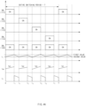
- FIG. 3 is a view for describing an operation of a battery rack management apparatus according to an embodiment disclosed herein.
- the control unit 190 of the battery rack management apparatus 100 may turn on at least one of the plurality of power switches 110. According to an embodiment, the control unit 190 may sequentially turn on the first power switch 111, the second power switch 112, the third power switch 113, and the fourth power switch 114. According to an embodiment, while turning on any one of the plurality of power switches 110, the control unit 190 may turn on the control switch 130 together.
- the control unit 190 may set a switching period for all of the plurality of power switches 111, 112, 113, and 114 as T, and control the plurality of power switches 111, 112, 113, and 114 such that the turn-on/turn-off operations thereof are repeated.
- control unit 190 may turn on the first power switch 111 and the control switch 130 for a period of time 0 to t 1 , turn on the second power switch 112 and the control switch 130 for a period of time t 2 to t 3 , turn on the third power switch 114 and the control switch 130 for a period of time t 4 to t 5 , turn on the fourth power switch 114 and the control switch 130 for a period of time t 6 to t 7 , and may turn off the plurality of power switches 111, 112, 113, and 114 and the control switch 130 for periods of time t 1 to t 2 , t 3 to t 4 , t 5 to t 6 , and t 7 to T.
- the current i sw flowing through the switching line connected to the turned-on power switch may increase in the same manner as the current i L flowing through the inductor 120 of the battery rack management apparatus 100.
- the control unit 190 turns on the first power switch 111 and the control switch 130 from 0 to t 1
- the current i sw1 flowing through the first switching line L 1 for the period of time 0 to t 1 may increase in the same manner as the current i L flowing through the inductor 120.
- a current in flowing through the first diode 140 or the second diode 150 may be reduced in the same manner as the current i L flowing through the inductor 120 of the battery rack management apparatus 100.
- the control unit 190 when the control unit 190 turns off all of the control switch 130 and the plurality of power switches 111, 112, 113, and 114 for periods of time t 1 to t 2 , t 3 to t 4 , t 5 to t 6 , and t 7 to T, the current i D flowing through the firs diode 140 or the second diode 150 may be reduced in the same manner as the current i L flowing through the inductor 120.
- the control unit 190 When the control unit 190 turns on each of the plurality of power switches 111, 112, 113, and 114, the currents i sw1 , i sw2 , i sw3 , and i sw4 respectively sensed in the switching lines L 1 , L 2 , L 3 , and L 4 may be in a mutually balanced state.
- the control unit 190 when the control unit 190 turns on each of the first power switch 111, the second power switch 112, the third power switch 113, or the fourth power switch 114 together with the control switch 130, the average values of the currents i sw1 , i sw2 , i sw3 , and/or i sw4 respectively flowing through the first switching line L 1 , the second switching line L 2 , the third switching line L 3 , and/or the fourth switching line L 4 may be equal to each other.
- the average value of current i sw1 flowing through the first switching line L 1 for the period of time 0 to t 1 may be equal to the average value of current i sw2 flowing through the second switching line L 2 for the period of time t 2 to t 3 , the average value of current i sw3 flowing through the third switching line L 3 for the period of time t 4 to t 5 , and/or the average value of current i sw4 flowing through the fourth switching line L 4 for the period of time t 6 to t 7 .
- the control unit 190 when the control unit 190 turns on each of the first power switch 111, the second power switch 112, the third power switch 113, or the fourth power switch 114 together with the control switch 130, the peak values of the currents i sw1 , i sw2 , i sw3 , and/or i sw4 respectively flowing through the first switching line L 1 , the second switching line L 2 , the third switching line L 3 , and/or the fourth switching line L 4 may be equal to each other, or the currents when a specific time elapses may be equal to each other.
- the control unit 190 may receive the currents i sw1 , i sw2 , i sw3 , and i sw4 of the respective switching lines L 1 , L 2 , L 3 , and L 4 from the first sensing unit 170.
- the control unit 190 may control each of the plurality of power switches 111, 112, 113, and 114 and/or the control switch 130 to increase, decrease, or maintain the turn-on times thereof, so that each of the currents i sw1 , i sw2 , i sw3 , and i sw4 may reach a balanced state.
- the switching duty of each of the plurality of power switches 110 and/or the control switch 130 may be increased, decreased, or maintained.
- a specific method, in which the control unit 190 increases, decreases, or maintains the turn-on times and/or switching duties of the plurality of power switches 110 and/or the control switch 130 on the basis of the currents i sw1 , i sw2 , i sw3 , and i sw4 received from the first sensing unit 170, will be described later with reference to FIGS. 4A , 4B , and 4C .
- the control unit 190 may receive, from the second sensing unit 180, the voltage applied to the capacitor 160.
- the control unit 190 may increase the turn-on times of the plurality of power switches 111, 112, 113, and 114 and the control switch 130 when the voltage received from the second sensing unit 180 is less than a reference value.
- the control unit 190 may maintain the switching duty by increasing the turn-off time at the same rate as the increase rate of the turn-on time of each of the plurality of power switches 111, 112, 113, and 114 and the control switch 130.
- control unit 190 increases the turn-on times of the plurality of power switches 111, 112, 113, and 114 and/or the control switch 130 on the basis of the voltage received from the second sensing unit 180, will be described later with reference to FIG. 5 .
- FIGS. 4A , 4B , and 4C are views for describing an operation of the battery rack management apparatus on the basis of currents sensed by the first sensing unit according to an embodiment disclosed herein.
- the control unit 190 may set a set value as an average value of a first value and a second value.
- the control unit 190 may control the operations of the power switches 110 so that the average value of each of the currents i sw1 , i sw2 , i sw3 , and i sw4 respectively sensed in the switching lines L 1 , L 2 , L 3 , and L 4 corresponds to the set value.
- the average value of the current i sw1 flowing through the first switching line L 1 may be equal to the set value.
- the average value of the current i sw2 flowing through the second switching line L 2 while the control unit 190 turns on the second power switch 112 (t 2 to t 3 ) and the average value of the current i sw4 flowing through the fourth switching line L 4 while the control unit 190 turns on the fourth power switch 114 (t 6 to t 7 ) may be less than the set value.
- the control unit 190 While the control unit 190 turns on the third power switch 113 (t 4 to t 5 ), the average value of the current i sw3 flowing through the third switching line L 3 may exceed the set value. In this case, in order to balance the currents flowing through the plurality of switching lines L 1 , L 2 , L 3 , and L 4 , the control unit 190 may regulate the turn-on time and/or turn-off time of each of the plurality of power switches 111, 112, 113, and 114.
- the control unit 190 may determine that the average value of the current i sw1 flowing through the first switching line L 1 is equal to the set value, and maintain the turn-on time of the first power switch 111 connected to the first switching line L 1 . In this case, the control unit 190 may maintain the switching duty of the first power switch 111 by maintaining the turn-off time of the first power switch 111 together.
- the control unit 190 may determine that the average value of the current i sw2 flowing through the second switching line L 2 is less than the set value, and increase the turn-on time of the second power switch 112 connected to the second switching line L 2 to t 2 to t 3 '.
- the control unit 190 may determine that the average value of the current i sw3 flowing through the third switching line L 3 is greater than the set value, and reduce the turn-on time of the third power switch 113 connected to the third switching line L 3 to t 4 ' to t 5 '.
- the control unit 190 may determine that the average value of the current i sw4 flowing through the fourth switching line L 4 is less than the set value, and increase the turn-on time of the fourth power switch 114 connected to the fourth switching line L 4 to t 6 ' to t 7 '.
- control unit 190 increases, decreases, or maintains the turn-on time of each of the plurality of power switches, the entire switching period, during which the on/off operations of all of the plurality of power switches 110 are repeated, may be adjusted to T'.
- the control unit 190 may reduce the turn-on times and turn-off times of the plurality of power switches 111, 112, 113, and 114 at the same rate, so that the entire switching period adjusted to T' in FIG. 4B is adjusted back to the previous switching period T.
- the control unit 190 reduces the turn-on times and turn-off times of the plurality of power switches 111, 112, 113, and 114 at the same rate, and thus, the switching duty of each of the plurality of power switches 111, 112, 113, and 114 may be maintained the same as that before the reduction.
- the currents flowing through the plurality of switching lines L 1 , L 2 , L 3 , and L 4 may maintain a mutual balance.
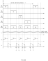
- FIG. 5 is a view for describing an operation of the battery rack management apparatus on the basis of the voltage sensed by the second sensing unit according to an embodiment disclosed herein.
- the voltage of the capacitor 160 sensed by the second sensing unit 180 may be less than a preset reference value.
- the control unit 190 may increase the turn-on times of the plurality of power switches 111, 112, 113, and 114 so that the voltage transmitted to the load 20 from the battery rack management apparatus 100 becomes greater than or equal to the reference value.
- the control unit 190 may increase the turn-on times of the plurality of power switches 111, 112, 113, and 114 at a rate of T " T in order to increase the entire switching period from T to T". In this case, the control unit 190 may increase the turn-on times of all of the plurality of power switches 111, 112, 113, and 114.
- An imbalance of the output of the plurality of battery racks 10 may be caused when the control unit 190 increases the turn-on times of only some of the plurality of power switches 111, 112, 113, and 114.
- the control unit 190 may increase the turn-off times of the plurality of power switches 111, 112, 113, and 114 at the same rate as the increase rate of the turn-on times of the plurality of power switches 111, 112, 113, and 114.
- the control unit 190 may maintain the same switching duty before and after increasing the turn-on time and turn-off time of each of the plurality of power switches 111, 112, 113, and 114.
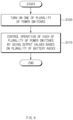
- FIG. 6 is a flowchart showing a method for operating a battery rack management apparatus according to an embodiment disclosed herein.
- the method for operating a battery rack management apparatus 100 may include turning on one of a plurality of power switches 111, 112, 113, and 114 included in the battery rack management apparatus 100 (S100) and controlling an operation of each of the plurality of power switches 111, 112, 113, and 114 by using outputs based on a plurality of battery racks 1, 2, 3, and 4 (S110).
- the control unit 190 included in the battery rack management apparatus 100 may turn on one of the plurality of power switches 111, 112, 113, and 114 so that the plurality of power switches 111, 112, 113, and 114 included in the battery rack management apparatus 100 are connected to the plurality of battery racks 1, 2, 3, and 4 via a plurality of switching lines L 1 , L 2 , L 3 , and L 4 , respectively.
- a control switch 130 included in the battery rack management apparatus 100 may be turned on together.
- the battery rack management apparatus 100 may control the operations of the plurality of power switches 111, 112, 113, and 114 so that at least one of the plurality of power switches 111, 112, 113, and 114 is turned on or turned off by using the outputs based on the plurality of battery racks 1, 2, 3, and 4. In this case, the battery rack management apparatus 100 may control the on/off operations of each of the plurality of power switches 111, 112, 113, and 114 and the control switch 130 together.
- the outputs based on the plurality of battery racks 1, 2, 3, and 4 may correspond to currents of the plurality of switching lines L 1 , L 2 , L 3 , and L 4 sensed in the battery rack management apparatus 100 according to the disclosure herein or correspond to the output voltage transmitted to a load 20 and/or a capacitor 160.
- the first sensing unit 170 may sense currents flowing through the plurality of switching lines L 1 , L 2 , L 3 , and L 4 .
- the second sensing unit 180 may sense the voltage transmitted to the capacitor 160.
- the voltage of the capacitor 160 sensed by the second sensing unit 180 may be the same as the voltage transmitted to the load 20.
- FIGS. 7A , 7B , and 7C are flowcharts more specifically showing the method for operating a battery rack management apparatus according to an embodiment disclosed herein.
- the operations illustrated in FIGS. 7A , 7B , and 7C may be examples of operation S110 illustrated in FIG. 6 .
- the battery rack management apparatus 100 may regulate the switching duties of the plurality of power switches 111, 112, 113, and 114 on the basis of the output current of each of the plurality of battery racks 10.
- the battery rack management apparatus 100 may sense the currents of the switching lines L 1 , L 2 , L 3 , and L 4 to which the plurality of battery racks 1, 2, 3 and 4 and the plurality of power switches 111, 112, 113, and 114 are respectively connected (S111).
- the first sensing unit 170 included in the battery rack management apparatus 100 may transmit the sensed currents i sw1 , i sw2 , i sw3 , and i sw4 to the control unit 190.
- the control unit 190 may regulate the turn-on time and/or switching duty of each of the plurality of power switches 111, 112, 113, and 114. In this case, the turn-on time and/or switching duty of the control switch 130 may also be regulated together.
- the battery rack management apparatus 100 may check whether currents i sw1 , i sw2 , i sw3 , and i sw4 less than a predetermined set value are sensed in the plurality of switching lines L 1 , L 2 , L 3 , and L 4 , respectively (5112) .
- the control unit 190 may increase the turn-on time of the power switch which is connected to the switching line in which the current less than the set value is sensed (S113).
- the control unit 190 may maintain the turn-off time of the power switch in which the turn-on time has increased. In this case, the switching duty of the power switch in which the turn-on time has increased may increase.
- the control unit 190 may increase the turn-on time of the control switch 130 together while increasing the turn-on time of the power switch.
- the control unit 190 may check whether the currents of the switching lines L 1 , L 2 , L 3 , and L 4 , in which currents greater than or equal to the set value have been sensed in operation S112, are greater than the set value (S114).
- the control unit 190 may decrease the turn-on time of the power switch which is connected to the switching line in which the current greater than the set value is sensed (S115).
- the control unit 190 may maintain the turn-off time of the power switch in which the turn-on time has decreased. In this case, the switching duty of the power switch in which the turn-on time has decreased may decrease.
- the control unit 190 may decrease the turn-on time of the control switch 130 together while decreasing the turn-on time of the power switch.
- the control unit 190 may maintain the turn-on time and turn-off time of the power switch connected to the switching line in which it is determined that the same current as the set value is sensed by operations S112 and S114. In this case, the control unit 190 may maintain the turn-on time and turn-off time of the control switch 130 together.
- the battery rack management apparatus 100 may regulate the switching duty of the power switch 110 on the basis of the voltage transmitted to the load 20.
- the second sensing unit 180 may sense the voltage applied to the capacitor 160 (S116).
- the voltage transmitted to the load 20 may be the same as the voltage applied to the capacitor 160.
- the second sensing unit 180 may sense the voltage applied to the capacitor 160 and transmit the voltage to the control unit 190.
- the control unit 190 may regulate the turn-on time and turn-off time of each of the power switches 110 on the basis of the voltage of the capacitor 160 received from the second sensing unit 180. In this case, the control unit 190 may also regulate the turn-on time and turn-off time of the control switch 130 together.
- control unit 190 may regulate the turn-on time and turn-off time of each of the plurality of power switches 111, 112, 113, and 114 and/or the control switch 130 at the same rate, and thus, the switching duty may be maintained before and after the regulation.
- the battery rack management apparatus 100 may check whether the voltage transmitted to the load 20 is less than a reference value (S117).
- the controller 190 may increase the turn-on time and turn-off time of the plurality of power switches 111, 112, 113, and 114 (S118).
- the control unit 190 may increase the turn-on time and turn-off time of the control switch 130 together.
- the control unit 190 may regulate the turn-on time and turn-off time of each of the plurality of power switches 111, 112, 113, and 114 at the same rate, and thus, the switching duty may be maintained before and after the increase in the turn-on time and turn-off time.
- control unit 190 may maintain the turn-on times and turn-off times of the plurality of power switches 111, 112, 113, and 114 and the control switch 130.
- the battery rack management apparatus 100 may regulate the switching duties of the plurality of power switches on the basis of the output current of each of the plurality of battery racks 10 and the output voltage transmitted to the load 20.
- the first sensing unit 17 may sense the currents i sw1 , i sw2 , i sw3 , and i sw4 that flow through the switching lines L 1 , L 2 , L 3 , and L 4 to which the plurality of battery racks 10 and the plurality of power switches 110 are respectively connected (S200).
- Operation S200 may be substantially the same as operation S111 of FIG. 7A .
- the battery rack management apparatus 100 may determine whether the current sensed in operation S200 is less than a predetermined set value (S210). Operation S210 may be substantially the same as operation S112 of FIG. 7A .
- the control unit 190 may increase the turn-on time and/or switching duty of the power switch which is connected to the switching line in which the current less than the set value is sensed in operation S210 (S211). Operation S211 may be substantially the same as operation S113 of FIG. 7A . The control unit 190 may determine that the current of the switching line, in which the current greater than or equal to the set value is sensed in operation S210, is greater than the set value (S212). Operation S212 may be substantially the same as operation S114 of FIG. 7A . The control unit 190 may decrease the turn-on time and/or switching duty of the power switch which is connected to the switching line in which the current greater than the set value is sensed in operation S212 (S213).
- Operation S213 may be substantially the same as operation S115 of FIG. 7A .
- the control unit 190 may maintain the turn-on time and/or switching duty of the power switch of the switching line in which it is determined that the same current as the set value is sensed by operations S210 and S212.
- the control unit 190 may maintain the balance of the output of the battery rack 10 through operations S200, S210, S211, S212, and/or S213.
- the battery rack management apparatus 100 increases (S211), decreases (S213), or maintains the turn-on times or switching duties of the plurality of power switches 111, 112, 113, and 114 so that the output of the battery rack 10 is balanced, and then may sense the voltage applied to the capacitor 160 (S220).
- Operation S220 may be substantially the same as operation S116 of FIG. 7B .
- the voltage applied to the capacitor 160 may be the same as the voltage transmitted from the battery rack management apparatus 100 to the load 20.
- the control unit 190 may regulate the turn-on times and turn-off times of the plurality of power switches 110 on the basis of the voltage of the capacitor 160 sensed by the second sensing unit 180.
- the control unit 190 may maintain the balance of current output from the battery rack 10, and increase the turn-on time and turn-off time of the power switch 110 so that the voltage transmitted to the load 20 becomes greater than or equal to the reference value (S222). Operation S222 may be substantially the same as operation S118 of FIG. 7B . In operation S222, the control unit 190 increases the turn-on time and turn-off time of the power switch 110 at the same rate, and thus, the switching duties of the plurality of power switches 111, 112, 113, and 114 are maintained the same.
Landscapes
- Engineering & Computer Science (AREA)
- Power Engineering (AREA)
- Manufacturing & Machinery (AREA)
- Chemical & Material Sciences (AREA)
- Chemical Kinetics & Catalysis (AREA)
- Electrochemistry (AREA)
- General Chemical & Material Sciences (AREA)
- Microelectronics & Electronic Packaging (AREA)
- Charge And Discharge Circuits For Batteries Or The Like (AREA)
- Direct Current Feeding And Distribution (AREA)
Abstract
Description
- The present invention claims the benefit of the priority of
Korean Patent Application No. 10-2021-0150004, filed on November 03, 2021 - Embodiments disclosed herein relate to a battery rack management apparatus and a method for operating same.
- Due to climate change caused by global warming and the depletion of various fossil fuels, the importance of new and renewable energy is increasing. However, since most of the new and renewable energy is based on natural energy, an output fluctuates greatly, and it is not easy to control the amount of power generation. In fact, the new and renewable energy using sunlight or wind power can acquire energy intermittently, and thus, it is difficult to match the obtained energy with consumption patterns. Therefore, in order for the new and renewable energy to be widely used, there is a need for an energy storage system (ESS), which is a means for storing intermittently generated energy and then stably supplying the energy.
- The ESS is a system capable of storing generated power and stably supplying the power according to a demand pattern, and refers to a storage device that stores excessively produced power from a power plant and transmits the power when there is a temporary power shortage. The ESS can not only store energy and use the energy when needed, but also send stored energy to places where power is insufficient or sell the energy to electric power companies. The ESS includes a plurality of battery racks connected in series, parallel, or series-parallel.
- When battery racks of an energy storage system are connected in parallel to a load, a difference may occur in the use states (e.g., voltages, charge amounts, or life spans) of a plurality of connected battery racks due to continuous charging or discharging. Accordingly, an imbalance may occur in the currents output from the battery racks. The imbalance in output currents can cause a current to concentrate in a specific battery rack, shorten the lifespan of a battery, or reduce the capacity of the energy storage system, thereby destabilizing the system.
- In order to solve the output imbalance of the battery racks, converters for individually adjusting the outputs of the battery racks are generally used by being connected to respective battery racks. However, since the converters have to be used individually for each of the plurality of battery racks, the volume and cost are increased. In addition, there is also difficulty in controlling each of the plurality of converters.
- In the background art and the problem to be solved by the invention, matters described as the related art are only for the purpose of improving the understanding of the present invention. Therefore, it should not be considered that these matters correspond to the related art already known to those skilled in the art.
- A battery rack management apparatus according to an embodiment disclosed herein includes: a plurality of power switches respectively connected to a plurality of battery racks; and a control unit configured to turn on at least one of the plurality of power switches and use output values based on the plurality of battery racks to control an operation of each of the plurality of power switches.
- In an embodiment, the battery rack management apparatus may further include a first sensing unit that senses currents that flow in a plurality of switching lines for connecting the plurality of battery racks to the plurality of power switches, wherein the operation of each of the plurality of the power switches is controlled on the basis of the currents sensed by the first sensing unit.
- In an embodiment, the battery rack management apparatus may control a turn-on time or a switching duty of each of the plurality of power switches so that each of the currents flowing through the plurality of switching lines corresponds to a set value.
- In an embodiment, in the battery rack management apparatus, the set value may be an average value of the currents sensed by the first sensing unit.
- In an embodiment, the battery rack management apparatus may increase the turn-on time or the switching duty of the power switch connected to the switching line of the plurality of switching lines in which the current is less than the set value and may reduce the turn-on time or the switching duty of the power switch connected to the switching line of the plurality of switching lines in which the current is greater than the set value.
- In an embodiment, the battery rack management apparatus may further include: an inductor connected to the plurality of power switches at a first node; and a control switch of which one end is connected to the inductor at a second node and the other end is connected to a third node.
- In an embodiment, the battery rack management apparatus may further include: a first diode of which one end is connected to the first node and the other end is connected to the third node; a second diode of which one end is connected to the second node and the other end is connected to a fourth node; and a capacitor which is connected to a load and of which one end is connected to the fourth node and the other end is connected to the third node.
- In an embodiment, the battery rack management apparatus may further include a second sensing unit configured to sense a voltage applied to the capacitor, and may control the operation of each of the plurality of power switches on the basis of the voltage.
- In an embodiment, the battery rack management apparatus may increase the turn-on times of the plurality of power switches when the voltage applied to the capacitor is less than a reference value.
- A method according to an embodiment disclosed herein is to operate a battery rack management apparatus that includes a plurality of power switches respectively connected to a plurality of battery racks and a control unit connected to the power switches, the method including: the control unit turning on at least one of the plurality of power switches; and the control unit using output values based on the plurality of battery racks, thereby controlling an operation of each of the plurality of power switches.
- In an embodiment, the method for operating the battery rack management apparatus may further include: a first sensing unit sensing currents that flow in a plurality of switching lines for connecting the plurality of battery racks to the plurality of power switches; and the currents controlling a turn-on time or a switching duty of each of the plurality of power switches.
- In an embodiment, in the method for operating the battery rack management apparatus, the set value may be an average value of the currents sensed by the first sensing unit.
- In an embodiment, the battery rack management apparatus may further include an inductor connected to the plurality of power switches, a control switch connected to the inductor, a capacitor connected to the inductor, and a second sensing unit connected to the capacitor, and the method for operating the battery rack management apparatus may further include: the second sensing unit sensing a voltage applied to the capacitor; and the control unit controlling a turn-on time of each of the plurality of power switches on the basis of the voltage.
- A battery rack management apparatus disclosed herein can solve the problems of shortening of a battery life, reduction in the capacity of an energy storage system, or instability of the energy storage system due to current imbalance.
- The battery rack management apparatus according to the disclosure herein can be commonly connected to a plurality of battery racks as a single device, and thus, it is possible to minimize the volume of devices added to the energy storage system.
- The battery rack management apparatus according to the disclosure herein can be commonly connected to a plurality of battery racks, and thus, it is possible to minimize the cost required to additionally equip a device for each of the plurality of battery racks.
- The battery rack management apparatus according to the disclosure herein is commonly connected to a plurality of battery racks and can independently control each of the plurality of battery racks, and thus, it is possible to facilitate the design for controlling an energy storage system.
-
-
FIG. 1 is a view showing a battery rack management apparatus, a plurality of battery racks, and a load according to an embodiment disclosed herein. -
FIG. 2 is a circuit diagram showing a battery rack management apparatus according to an embodiment disclosed herein. -
FIG. 3 is a view for describing an operation of a battery rack management apparatus according to an embodiment disclosed herein. -
FIGS. 4A ,4B , and4C are views for describing an operation of the battery rack management apparatus on the basis of currents sensed by a first sensing unit according to an embodiment disclosed herein. -
FIG. 5 is a view for describing an operation of the battery rack management apparatus on the basis of the voltage sensed by a second sensing unit according to an embodiment disclosed herein. -
FIG. 6 is a flowchart showing a method for operating a battery rack management apparatus according to an embodiment disclosed herein. -
FIGS. 7A ,7B , and7C are flowcharts more specifically showing the method for operating a battery rack management apparatus according to an embodiment disclosed herein. - In the description with reference to the drawings, identical or similar reference symbols are used for identical or similar elements.
- Hereinafter, various embodiments of the present invention will be described with reference to the accompanying drawings. However, this does not limit the present invention within specific embodiments, but it should be understood that the present invention covers all the modifications, equivalents, and alternatives for the embodiments of the present invention.
- It should be appreciated that various embodiments and the terms used herein are not intended to limit the technical features set forth herein to particular embodiments and include various modifications, equivalents, and alternatives for a corresponding embodiment. In the description with reference to the drawings, similar reference symbols are used for similar or related elements. The singular form of a noun corresponding to an item may include one or more items, unless the relevant context clearly dictates otherwise.
- As used herein, each of such phrases as "A or B," "at least one of A and B," "at least one of A or B," "A, B, or C," "at least one of A, B, and C," and "at least one of A, B, or C" may include any one of or all possible combinations of the items enumerated together in a corresponding one of the phrases. Also, such terms as "1st" or "2nd," "first" or "second," "A" or "B," and "(a)" or "(b)" may be used to simply distinguish a corresponding component from another, and does not limit the components in other aspect (e.g., importance or order) unless explicitly described to the contrary.
- As used herein, if an element (e.g., a first element) is referred to, with or without the term "functionally" or "communicatively," as being "linked to," "coupled to," "connected to," "coupled with," or "connected with" another element (e.g., a second element), it means that this element may be connected to another element directly (e.g., by a line), wirelessly, or via a third element.
- According to an embodiment, a method according to various embodiments disclosed herein may be included and provided in a computer program product. The computer program product may be traded as a commodity between a seller and a buyer. The computer program product may be distributed in the form of a machine-readable storage medium (e.g., compact disc read only memory (CD-ROM)), or be distributed (e.g., downloaded or uploaded) online via an application store or directly between two user devices. When distributed online, at least part of the computer program product may be at least temporarily stored or provisionally generated in the machine-readable storage medium, such as memory of a manufacturer server, an application store server, or a relay server.
- According to various embodiments, each component (e.g., module or program) of the above-described components may include a single entity or a plurality of entities, and some of the entities may be separately disposed in another component. According to various embodiments, one or more operations or components of the above-described components may be omitted, or one or more other operations or components may be added. Alternatively or additionally, a plurality of components (e.g., modules or programs) may be integrated into a single component. In such a case, the integrated component may perform one or more functions of each of the plurality of components in the same or similar manner as these functions are performed by a corresponding component of the plurality of components before the integration. According to various embodiments, operations performed by the module, the program, or another component may be performed sequentially, in parallel, repeatedly, or heuristically, one or more of the operations may be executed in a different order or omitted, or one or more other operations may be added.
-
FIG. 1 is a view showing a battery rack management apparatus, a plurality of battery racks, and a load according to an embodiment disclosed herein. - Referring to
FIG. 1 , abattery rack 10 may include a plurality ofbattery racks battery rack 10 may be connected to the batteryrack management apparatus 100 via a plurality of switching lines L1, L2, L3, and L4. According to an embodiment, afirst battery rack 1 may be connected to the batteryrack management apparatus 100 via a first switching line L1, asecond battery rack 2 may be connected thereto via a second switching line L2, athird battery rack 3 may be connected thereto via a third switching line L3, and afourth battery rack 4 may be connected thereto via a fourth switching line L4. For example, the number of the plurality ofbattery racks 10 connectable to the batteryrack management apparatus 100 is illustrated as four inFIG. 1 , but the embodiment is not limited thereto. The batteryrack management apparatus 100 may be configured to be connectable to n battery racks (where n is a natural number of 2 or more). The plurality ofbattery racks rack management apparatus 100 at the same time or different times. Thebattery rack 10 may supply power to the batteryrack management apparatus 100. - The battery
rack management apparatus 100 may be connected to aload 20. The batteryrack management apparatus 100 may transmit, to theload 20, the power transmitted from the plurality ofbattery racks rack management apparatus 100 may operate as a converter. - The battery
rack management apparatus 100 may sense current values of currents that flow through the plurality of switching lines L1, L2, L3, and L4 respectively connected to the plurality ofbattery racks rack management apparatus 100 may determine whether the balance of outputs of the plurality ofbattery racks rack management apparatus 100 may regulate the outputs of the plurality ofbattery racks - The battery
rack management apparatus 100 may sense a voltage transmitted to theload 20. The batteryrack management apparatus 100 may determine whether the voltage transmitted to theload 20 is greater than or equal to a preset reference value. On the basis of the sensed voltage, the batteryrack management apparatus 100 may regulate the outputs of the plurality ofbattery racks rack management apparatus 100 according to an embodiment disclosed herein will be described below with reference toFIGS. 2 to 7C . -
FIG. 2 is a circuit diagram showing a battery rack management apparatus according to an embodiment disclosed herein. - Referring to
FIG. 2 , the batteryrack management apparatus 100 may include apower switch 110, aninductor 120, acontrol switch 130, afirst diode 140, asecond diode 150, acapacitor 160, afirst sensing unit 170, asecond sensing unit 180, and/or acontrol unit 190. - The
power switch 110 may include a plurality of power switches 111, 112, 113, and 114. Thepower switch 110 may be connected to thebattery rack 10 via a plurality of switching lines L1, L2, L3, and L4. According to an embodiment, afirst power switch 111 may be connected to afirst battery rack 1 via a first switching line L1, asecond power switch 112 may be connected to asecond battery rack 2 via a second switching line L2, athird power switch 113 may be connected to athird battery rack 3 via a third switching line L3, and afourth power switch 114 may be connected to afourth battery rack 4 via a fourth switching line L4. According to an embodiment, thepower switch 110 may include a metal oxide semiconductor field effect transistor (MOSFET) element. - The
inductor 120 may be connected to the plurality of power switches 111, 112, 113, and 114 at a first node n1. According to an embodiment, theinductor 120 may be connected to a drain terminal of each of the plurality of power switches 111, 112, 113, and 114 at the first node n1. - The
control switch 130 may have one end connected to theinductor 120 at a second node n2 and the other end connected to a third node n3. According to an embodiment, thecontrol switch 130 may include a MOSFET element. - The
first diode 140 may have one end connected to the first node n1 and the other end connected to the third node n3. According to an embodiment, a cathode end of thefirst diode 140 may be connected to the first node n1, and an anode end thereof may be connected to the third node n3. - The
second diode 150 may have one end connected to the second node n2 and the other end connected to a fourth node n4. According to an embodiment, an anode end of thesecond diode 150 may be connected to the second node n2, and a cathode end thereof may be connected to the fourth node n4. - The
capacitor 160 may have one end connected to the third node n3 and the other end connected to the fourth node n4. Thecapacitor 160 may be connected to theload 20. According to an embodiment, thecapacitor 160 may be connected in parallel to theload 20. - The
first sensing unit 170 may be connected to each of the plurality of switching lines L1, L2, L3, and L4. - The
second sensing unit 180 may be connected to thecapacitor 160. According to an embodiment, thesecond sensing unit 180 may be connected in parallel to thecapacitor 160. - The
control unit 190 may be connected to thepower switch 110, thefirst sensing unit 170, and/or thesecond sensing unit 180. According to an embodiment, thecontrol unit 190 may include a hardware device such as a processor or a central processing unit (CPU), or a program implemented by a hardware device. For example, components included in thecontrol unit 190 may be implemented as individual devices (or programs) or implemented as one integrated module. According to various embodiments, thecontrol unit 190 may include afirst sensing unit 170 and/or asecond sensing unit 180 as components. - Hereinafter, operations of components included in the battery
rack management apparatus 100 will be mainly described. - The
first sensing unit 170 may sense currents isw of the switching lines L1, L2, L3, and L4. Thefirst sensing unit 170 may transmit, to thecontrol unit 190, the currents isw sensed in the switching lines L1, L2, L3, and L4. - The
second sensing unit 180 may sense a voltage applied to thecapacitor 160. According to an embodiment, the voltage of thecapacitor 160 sensed by thesecond sensing unit 180 may be the same as the voltage transmitted to theload 20. The second sensing unit may transmit, to thecontrol unit 190, the voltage sensed in thecapacitor 160. - The
control unit 190 may turn on or turn off at least one of the plurality of power switches 111, 112, 113, and 114. In this case, thecontrol unit 190 may turn on or turn off thecontrol switch 130 together. According to an embodiment, when thecontrol unit 190 turns on thecontrol switch 130 and at least one of the plurality of power switches 111, 112, 113, and 114, the battery rack (e.g., 1, 2, 3, and/or 4) connected to the turned-on power switch, the turned-on power switch (e.g., 111, 112, 113, and/or 114), theinductor 120, and thecontrol switch 130 may form a closed circuit. For example, when thecontrol unit 190 turns on thefirst power switch 111 and thecontrol switch 130, thefirst battery rack 1, thefirst power switch 111, theinductor 120, and thecontrol switch 130 may form a closed circuit. In this case, thefirst diode 140 and/or thesecond diode 150 may be reverse biased. According to another embodiment, when thecontrol unit 190 turns off thecontrol switch 130 and the plurality of power switches 111, 112, 113, and 114, theinductor 120, thefirst diode 140, thesecond diode 150, and thecapacitor 160 may form a closed circuit. - The
control unit 190 may regulate outputs of the plurality ofbattery racks first sensing unit 170. In order to regulate the outputs of the plurality ofbattery racks control unit 190 may control turn-on and/or turn-off operations of the plurality of power switches 111, 112, 113, and 114) or control a switching duty of each of the plurality of power switches 111, 112, 113, and 114. In this case, thecontrol unit 190 may control the turn-on and/or turn-off operation of thecontrol switch 130 together or control a switching duty thereof together. - The
control unit 190 may determine whether the current received from thefirst sensing unit 170 corresponds to a predetermined set value. Thecontrol unit 190 may control the turn-on time, turn-off time, and/or switching duty of thecontrol switch 130 and/or each of the plurality of power switches 111, 112, 113, and 114 so that each of the currents flowing in the plurality of switching lines L1, L2, L3, and L4 corresponds to the set value. Thecontrol unit 190 may set the set value. According to an embodiment, thecontrol unit 190 may be set as an average value of currents isw1, isw2, isw3, and isw4 of the plurality of switching lines L1, L2, L3, and L4. A detailed operation, in which thecontrol unit 190 controls the plurality of power switches 111, 112, 113, and 114 and/or thecontrol switch 130 on the basis of the current isw received from thefirst sensing unit 170, will be described later with reference toFIGS. 4A ,4B and4C . - The
control unit 190 may regulate the outputs of the plurality ofbattery racks second sensing unit 180. In order to regulate the outputs of the plurality ofbattery racks control unit 190 may control the turn-on and/or turn-off operations of the plurality of power switches 111, 112, 113, and 114. In this case, thecontrol unit 190 may control the turn-on and/or turn-off operation of thecontrol switch 130 together. According to an embodiment, thecontrol unit 190 may control the plurality of power switches 111, 112, 113, and 114 such that the power switches have the same switching duty. For example, when thecontrol unit 190 controls the turn-on and turn-off operations of the plurality of power switches 111, 112, 113, and 114, the turn-on time and turn-off time of each of the plurality of power switches 111, 112, 113, and 114 is regulated, and rates of the turn-on times and turn-off times before and after the regulation may be maintained the same. - The
control unit 190 may determine whether the voltage received from thesecond sensing unit 180 is greater than or equal to a preset reference value. Thecontrol unit 190 may control the turn-on times and/or turn-off times of the plurality of power switches 111, 112, 113, and 114 and/or thecontrol switch 130 so that the voltage applied to thecapacitor 160 becomes greater than or equal to the reference value. According to an embodiment, when the voltages output from the plurality ofbattery racks 10 are the same as Vin, and the switching duties of the plurality ofpower switches 110 are the same as D, the reference value may be set as in Equation (1) .
- A detailed operation, in which the
control unit 190 controls the plurality of power switches 111, 112, 113, and 114 and/or thecontrol switch 130 on the basis of the voltage received from thesecond sensing unit 180, will be described inFIG. 5 . -
FIG. 3 is a view for describing an operation of a battery rack management apparatus according to an embodiment disclosed herein. - Referring to
FIG. 3 , thecontrol unit 190 of the batteryrack management apparatus 100 may turn on at least one of the plurality of power switches 110. According to an embodiment, thecontrol unit 190 may sequentially turn on thefirst power switch 111, thesecond power switch 112, thethird power switch 113, and thefourth power switch 114. According to an embodiment, while turning on any one of the plurality of power switches 110, thecontrol unit 190 may turn on thecontrol switch 130 together. - The
control unit 190 may set a switching period for all of the plurality of power switches 111, 112, 113, and 114 as T, and control the plurality of power switches 111, 112, 113, and 114 such that the turn-on/turn-off operations thereof are repeated. In this case, thecontrol unit 190 may turn on thefirst power switch 111 and thecontrol switch 130 for a period oftime 0 to t1, turn on thesecond power switch 112 and thecontrol switch 130 for a period of time t2 to t3, turn on thethird power switch 114 and thecontrol switch 130 for a period of time t4 to t5, turn on thefourth power switch 114 and thecontrol switch 130 for a period of time t6 to t7, and may turn off the plurality of power switches 111, 112, 113, and 114 and thecontrol switch 130 for periods of time t1 to t2, t3 to t4, t5 to t6, and t7 to T. - While the
control unit 190 turns on thecontrol switch 130 and one of the plurality of power switches 111, 112, 113, and 114, the current isw flowing through the switching line connected to the turned-on power switch may increase in the same manner as the current iL flowing through theinductor 120 of the batteryrack management apparatus 100. For example, when thecontrol unit 190 turns on thefirst power switch 111 and thecontrol switch 130 from 0 to t1, the current isw1 flowing through the first switching line L1 for the period oftime 0 to t1 may increase in the same manner as the current iL flowing through theinductor 120. - When the
control unit 190 turns off thecontrol switch 130 and the plurality of power switches 111, 112, 113, and 114, a current in flowing through thefirst diode 140 or thesecond diode 150 may be reduced in the same manner as the current iL flowing through theinductor 120 of the batteryrack management apparatus 100. For example, when thecontrol unit 190 turns off all of thecontrol switch 130 and the plurality of power switches 111, 112, 113, and 114 for periods of time t1 to t2, t3 to t4, t5 to t6, and t7 to T, the current iD flowing through thefirs diode 140 or thesecond diode 150 may be reduced in the same manner as the current iL flowing through theinductor 120. - When the
control unit 190 turns on each of the plurality of power switches 111, 112, 113, and 114, the currents isw1, isw2, isw3, and isw4 respectively sensed in the switching lines L1, L2, L3, and L4 may be in a mutually balanced state. According to an embodiment, when thecontrol unit 190 turns on each of thefirst power switch 111, thesecond power switch 112, thethird power switch 113, or thefourth power switch 114 together with thecontrol switch 130, the average values of the currents isw1, isw2, isw3, and/or isw4 respectively flowing through the first switching line L1, the second switching line L2, the third switching line L3, and/or the fourth switching line L4 may be equal to each other. For example, the average value of current isw1 flowing through the first switching line L1 for the period oftime 0 to t1 may be equal to the average value of current isw2 flowing through the second switching line L2 for the period of time t2 to t3, the average value of current isw3 flowing through the third switching line L3 for the period of time t4 to t5, and/or the average value of current isw4 flowing through the fourth switching line L4 for the period of time t6 to t7. In another example, when thecontrol unit 190 turns on each of thefirst power switch 111, thesecond power switch 112, thethird power switch 113, or thefourth power switch 114 together with thecontrol switch 130, the peak values of the currents isw1, isw2, isw3, and/or isw4 respectively flowing through the first switching line L1, the second switching line L2, the third switching line L3, and/or the fourth switching line L4 may be equal to each other, or the currents when a specific time elapses may be equal to each other. - The
control unit 190 may receive the currents isw1, isw2, isw3, and isw4 of the respective switching lines L1, L2, L3, and L4 from thefirst sensing unit 170. When the currents isw1, isw2, isw3, and isw4 of the respective switching lines L1, L2, L3, and L4 are not balanced, thecontrol unit 190 may control each of the plurality of power switches 111, 112, 113, and 114 and/or thecontrol switch 130 to increase, decrease, or maintain the turn-on times thereof, so that each of the currents isw1, isw2, isw3, and isw4 may reach a balanced state. In this case, as thecontrol unit 190 controls the turn-on times, the switching duty of each of the plurality ofpower switches 110 and/or thecontrol switch 130 may be increased, decreased, or maintained. A specific method, in which thecontrol unit 190 increases, decreases, or maintains the turn-on times and/or switching duties of the plurality ofpower switches 110 and/or thecontrol switch 130 on the basis of the currents isw1, isw2, isw3, and isw4 received from thefirst sensing unit 170, will be described later with reference toFIGS. 4A ,4B , and4C . - The
control unit 190 may receive, from thesecond sensing unit 180, the voltage applied to thecapacitor 160. Thecontrol unit 190 may increase the turn-on times of the plurality of power switches 111, 112, 113, and 114 and thecontrol switch 130 when the voltage received from thesecond sensing unit 180 is less than a reference value. Thecontrol unit 190 may maintain the switching duty by increasing the turn-off time at the same rate as the increase rate of the turn-on time of each of the plurality of power switches 111, 112, 113, and 114 and thecontrol switch 130. A specific method, in which thecontrol unit 190 increases the turn-on times of the plurality of power switches 111, 112, 113, and 114 and/or thecontrol switch 130 on the basis of the voltage received from thesecond sensing unit 180, will be described later with reference toFIG. 5 . -
FIGS. 4A ,4B , and4C are views for describing an operation of the battery rack management apparatus on the basis of currents sensed by the first sensing unit according to an embodiment disclosed herein. - Referring to
FIG. 4A , thecontrol unit 190 may set a set value as an average value of a first value and a second value. Thecontrol unit 190 may control the operations of the power switches 110 so that the average value of each of the currents isw1, isw2, isw3, and isw4 respectively sensed in the switching lines L1, L2, L3, and L4 corresponds to the set value. - While the
control unit 190 turns on the first power switch 111 (0 to t1), the average value of the current isw1 flowing through the first switching line L1 may be equal to the set value. The average value of the current isw2 flowing through the second switching line L2 while thecontrol unit 190 turns on the second power switch 112 (t2 to t3) and the average value of the current isw4 flowing through the fourth switching line L4 while thecontrol unit 190 turns on the fourth power switch 114 (t6 to t7) may be less than the set value. While thecontrol unit 190 turns on the third power switch 113 (t4 to t5), the average value of the current isw3 flowing through the third switching line L3 may exceed the set value. In this case, in order to balance the currents flowing through the plurality of switching lines L1, L2, L3, and L4, thecontrol unit 190 may regulate the turn-on time and/or turn-off time of each of the plurality of power switches 111, 112, 113, and 114. - Referring to
FIG. 4B , thecontrol unit 190 may determine that the average value of the current isw1 flowing through the first switching line L1 is equal to the set value, and maintain the turn-on time of thefirst power switch 111 connected to the first switching line L1. In this case, thecontrol unit 190 may maintain the switching duty of thefirst power switch 111 by maintaining the turn-off time of thefirst power switch 111 together. - The
control unit 190 may determine that the average value of the current isw2 flowing through the second switching line L2 is less than the set value, and increase the turn-on time of thesecond power switch 112 connected to the second switching line L2 to t2 to t3'. - The
control unit 190 may determine that the average value of the current isw3 flowing through the third switching line L3 is greater than the set value, and reduce the turn-on time of thethird power switch 113 connected to the third switching line L3 to t4' to t5'. - The
control unit 190 may determine that the average value of the current isw4 flowing through the fourth switching line L4 is less than the set value, and increase the turn-on time of thefourth power switch 114 connected to the fourth switching line L4 to t6' to t7'. - When the
control unit 190 increases, decreases, or maintains the turn-on time of each of the plurality of power switches 111, 112, 113, and 114, the switching duty of each of the power switches 111, 112, 113, and 114 may be increased, decreased, or maintained by maintaining the turn-off time. That is, thecontrol unit 190 may equally control the turn-off time of each of the plurality of power switches 111, 112, 113, and 114 as follows.Turn-off time = t1 to t2 = t3 to t4 = t3' to t4' = t5 to t6 = t5'to t6' = t7to t = t7' to T - As the
control unit 190 increases, decreases, or maintains the turn-on time of each of the plurality of power switches, the entire switching period, during which the on/off operations of all of the plurality ofpower switches 110 are repeated, may be adjusted to T'. - Referring to
FIG. 4C , thecontrol unit 190 may reduce the turn-on times and turn-off times of the plurality of power switches 111, 112, 113, and 114 at the same rate, so that the entire switching period adjusted to T' inFIG. 4B is adjusted back to the previous switching period T. Thecontrol unit 190 reduces the turn-on times and turn-off times of the plurality of power switches 111, 112, 113, and 114 at the same rate, and thus, the switching duty of each of the plurality of power switches 111, 112, 113, and 114 may be maintained the same as that before the reduction. In this case, the currents flowing through the plurality of switching lines L1, L2, L3, and L4 may maintain a mutual balance. -
FIG. 5 is a view for describing an operation of the battery rack management apparatus on the basis of the voltage sensed by the second sensing unit according to an embodiment disclosed herein. - Referring to
FIG. 5 , when the plurality of power switches 111, 112, 113, and 114 and thecontrol switch 130 included in the batteryrack management apparatus 100 operate as shown inFIG. 3 , the voltage of thecapacitor 160 sensed by thesecond sensing unit 180 may be less than a preset reference value. - The
control unit 190 may increase the turn-on times of the plurality of power switches 111, 112, 113, and 114 so that the voltage transmitted to theload 20 from the batteryrack management apparatus 100 becomes greater than or equal to the reference value. Thecontrol unit 190 may increase the turn-on times of the plurality of power switches 111, 112, 113, and 114 at a rate of
control unit 190 may increase the turn-on times of all of the plurality of power switches 111, 112, 113, and 114. - An imbalance of the output of the plurality of
battery racks 10 may be caused when thecontrol unit 190 increases the turn-on times of only some of the plurality of power switches 111, 112, 113, and 114. Thecontrol unit 190 may increase the turn-off times of the plurality of power switches 111, 112, 113, and 114 at the same rate as the increase rate of the turn-on times of the plurality of power switches 111, 112, 113, and 114. Thecontrol unit 190 may maintain the same switching duty before and after increasing the turn-on time and turn-off time of each of the plurality of power switches 111, 112, 113, and 114. -
FIG. 6 is a flowchart showing a method for operating a battery rack management apparatus according to an embodiment disclosed herein. - Referring to
FIG. 6 , the method for operating a batteryrack management apparatus 100 may include turning on one of a plurality of power switches 111, 112, 113, and 114 included in the battery rack management apparatus 100 (S100) and controlling an operation of each of the plurality of power switches 111, 112, 113, and 114 by using outputs based on a plurality ofbattery racks - In operation S100, the
control unit 190 included in the batteryrack management apparatus 100 may turn on one of the plurality of power switches 111, 112, 113, and 114 so that the plurality of power switches 111, 112, 113, and 114 included in the batteryrack management apparatus 100 are connected to the plurality ofbattery racks control switch 130 included in the batteryrack management apparatus 100 may be turned on together. - In operation S110, the battery
rack management apparatus 100 may control the operations of the plurality of power switches 111, 112, 113, and 114 so that at least one of the plurality of power switches 111, 112, 113, and 114 is turned on or turned off by using the outputs based on the plurality ofbattery racks rack management apparatus 100 may control the on/off operations of each of the plurality of power switches 111, 112, 113, and 114 and thecontrol switch 130 together. According to an embodiment, the outputs based on the plurality ofbattery racks rack management apparatus 100 according to the disclosure herein or correspond to the output voltage transmitted to aload 20 and/or acapacitor 160. Thefirst sensing unit 170 may sense currents flowing through the plurality of switching lines L1, L2, L3, and L4. Thesecond sensing unit 180 may sense the voltage transmitted to thecapacitor 160. The voltage of thecapacitor 160 sensed by thesecond sensing unit 180 may be the same as the voltage transmitted to theload 20. -
FIGS. 7A ,7B , and7C are flowcharts more specifically showing the method for operating a battery rack management apparatus according to an embodiment disclosed herein. The operations illustrated inFIGS. 7A ,7B , and7C may be examples of operation S110 illustrated inFIG. 6 . - Referring to
FIG. 7A , the batteryrack management apparatus 100 may regulate the switching duties of the plurality of power switches 111, 112, 113, and 114 on the basis of the output current of each of the plurality of battery racks 10. In order to sense each of currents isw1, isw2, isw3, and isw4 output from the plurality ofbattery racks rack management apparatus 100 may sense the currents of the switching lines L1, L2, L3, and L4 to which the plurality ofbattery racks first sensing unit 170 included in the batteryrack management apparatus 100 may transmit the sensed currents isw1, isw2, isw3, and isw4 to thecontrol unit 190. On the basis of the currents sensed by thefirst sensing unit 170 in operation S111, thecontrol unit 190 may regulate the turn-on time and/or switching duty of each of the plurality of power switches 111, 112, 113, and 114. In this case, the turn-on time and/or switching duty of thecontrol switch 130 may also be regulated together. - The battery
rack management apparatus 100 may check whether currents isw1, isw2, isw3, and isw4 less than a predetermined set value are sensed in the plurality of switching lines L1, L2, L3, and L4, respectively (5112) . Thecontrol unit 190 may increase the turn-on time of the power switch which is connected to the switching line in which the current less than the set value is sensed (S113). Thecontrol unit 190 may maintain the turn-off time of the power switch in which the turn-on time has increased. In this case, the switching duty of the power switch in which the turn-on time has increased may increase. Thecontrol unit 190 may increase the turn-on time of thecontrol switch 130 together while increasing the turn-on time of the power switch. - The
control unit 190 may check whether the currents of the switching lines L1, L2, L3, and L4, in which currents greater than or equal to the set value have been sensed in operation S112, are greater than the set value (S114). Thecontrol unit 190 may decrease the turn-on time of the power switch which is connected to the switching line in which the current greater than the set value is sensed (S115). Thecontrol unit 190 may maintain the turn-off time of the power switch in which the turn-on time has decreased. In this case, the switching duty of the power switch in which the turn-on time has decreased may decrease. Thecontrol unit 190 may decrease the turn-on time of thecontrol switch 130 together while decreasing the turn-on time of the power switch. - The
control unit 190 may maintain the turn-on time and turn-off time of the power switch connected to the switching line in which it is determined that the same current as the set value is sensed by operations S112 and S114. In this case, thecontrol unit 190 may maintain the turn-on time and turn-off time of thecontrol switch 130 together. - Referring to
FIG. 7B , the batteryrack management apparatus 100 may regulate the switching duty of thepower switch 110 on the basis of the voltage transmitted to theload 20. Thesecond sensing unit 180 may sense the voltage applied to the capacitor 160 (S116). The voltage transmitted to theload 20 may be the same as the voltage applied to thecapacitor 160. Thesecond sensing unit 180 may sense the voltage applied to thecapacitor 160 and transmit the voltage to thecontrol unit 190. Thecontrol unit 190 may regulate the turn-on time and turn-off time of each of the power switches 110 on the basis of the voltage of thecapacitor 160 received from thesecond sensing unit 180. In this case, thecontrol unit 190 may also regulate the turn-on time and turn-off time of thecontrol switch 130 together. According to an embodiment, thecontrol unit 190 may regulate the turn-on time and turn-off time of each of the plurality of power switches 111, 112, 113, and 114 and/or thecontrol switch 130 at the same rate, and thus, the switching duty may be maintained before and after the regulation. - The battery
rack management apparatus 100 may check whether the voltage transmitted to theload 20 is less than a reference value (S117). When determining that the voltage transmitted to theload 20 is less than the reference value, thecontroller 190 may increase the turn-on time and turn-off time of the plurality of power switches 111, 112, 113, and 114 (S118). In this case, thecontrol unit 190 may increase the turn-on time and turn-off time of thecontrol switch 130 together. According to an embodiment, thecontrol unit 190 may regulate the turn-on time and turn-off time of each of the plurality of power switches 111, 112, 113, and 114 at the same rate, and thus, the switching duty may be maintained before and after the increase in the turn-on time and turn-off time. - When the battery
rack management apparatus 100 determines that the voltage transmitted to theload 20 is greater than or equal to the reference value in operation S117, thecontrol unit 190 may maintain the turn-on times and turn-off times of the plurality of power switches 111, 112, 113, and 114 and thecontrol switch 130. - Referring to
FIG. 7C , the batteryrack management apparatus 100 may regulate the switching duties of the plurality of power switches on the basis of the output current of each of the plurality ofbattery racks 10 and the output voltage transmitted to theload 20. - In the battery
rack management apparatus 100, the first sensing unit 17 may sense the currents isw1, isw2, isw3, and isw4 that flow through the switching lines L1, L2, L3, and L4 to which the plurality ofbattery racks 10 and the plurality ofpower switches 110 are respectively connected (S200). Operation S200 may be substantially the same as operation S111 ofFIG. 7A . The batteryrack management apparatus 100 may determine whether the current sensed in operation S200 is less than a predetermined set value (S210). Operation S210 may be substantially the same as operation S112 ofFIG. 7A . Thecontrol unit 190 may increase the turn-on time and/or switching duty of the power switch which is connected to the switching line in which the current less than the set value is sensed in operation S210 (S211). Operation S211 may be substantially the same as operation S113 ofFIG. 7A . Thecontrol unit 190 may determine that the current of the switching line, in which the current greater than or equal to the set value is sensed in operation S210, is greater than the set value (S212). Operation S212 may be substantially the same as operation S114 ofFIG. 7A . Thecontrol unit 190 may decrease the turn-on time and/or switching duty of the power switch which is connected to the switching line in which the current greater than the set value is sensed in operation S212 (S213). Operation S213 may be substantially the same as operation S115 ofFIG. 7A . Thecontrol unit 190 may maintain the turn-on time and/or switching duty of the power switch of the switching line in which it is determined that the same current as the set value is sensed by operations S210 and S212. Thecontrol unit 190 may maintain the balance of the output of thebattery rack 10 through operations S200, S210, S211, S212, and/or S213. - The battery
rack management apparatus 100 increases (S211), decreases (S213), or maintains the turn-on times or switching duties of the plurality of power switches 111, 112, 113, and 114 so that the output of thebattery rack 10 is balanced, and then may sense the voltage applied to the capacitor 160 (S220). Operation S220 may be substantially the same as operation S116 ofFIG. 7B . The voltage applied to thecapacitor 160 may be the same as the voltage transmitted from the batteryrack management apparatus 100 to theload 20. Thecontrol unit 190 may regulate the turn-on times and turn-off times of the plurality of power switches 110 on the basis of the voltage of thecapacitor 160 sensed by thesecond sensing unit 180. Thecontrol unit 190 may maintain the balance of current output from thebattery rack 10, and increase the turn-on time and turn-off time of thepower switch 110 so that the voltage transmitted to theload 20 becomes greater than or equal to the reference value (S222). Operation S222 may be substantially the same as operation S118 ofFIG. 7B . In operation S222, thecontrol unit 190 increases the turn-on time and turn-off time of thepower switch 110 at the same rate, and thus, the switching duties of the plurality of power switches 111, 112, 113, and 114 are maintained the same. - Even though all the components constituting an embodiment disclosed herein have been described as being combined as one or operating in combination, embodiments disclosed herein are not necessarily limited to that embodiment. That is, within the scope of the objectives of the embodiments disclosed herein, all the components may be selectively combined into one or more and operate.
- Also, terms such as "include," "constitute," or "have" described above may mean that the corresponding components may be inherent unless explicitly described to the contrary, and thus should be construed as further including other components rather than excluding other components. Unless otherwise defined, all terms including technical or scientific terms have the same meanings as those generally understood by a person skilled in the art to which the embodiments disclosed herein pertain. Terms used generally such as terms defined in dictionaries should be interpreted as having the same meaning as in an associated technical context, and should not be understood abnormally or as having an excessively formal meaning unless defined apparently herein.
- The technical ideas disclosed herein have been described merely for illustrative purposes, and those skilled in the art, to which the embodiments disclosed herein pertain, will appreciate that various changes and modifications are possible without departing from the essential features of the embodiments disclosed herein. Therefore, the embodiments disclosed herein are intended to explain rather than limit the technical idea of the embodiments disclosed herein, and the scope of the technical idea disclosed herein is not limited by these embodiments. The protective scope disclosed herein should be interpreted by reference to the appended claims, and all technical ideas within their equivalents should be interpreted as being included in the scope of the disclosure.
Claims (13)
- A battery rack management apparatus comprising:a plurality of power switches respectively connected to a plurality of battery racks; anda control unit configured to turn on at least one of the plurality of power switches and use output values based on the plurality of battery racks to control an operation of each of the plurality of power switches.
- The battery rack management apparatus of claim 1, further comprising a first sensing unit that senses currents that flow in a plurality of switching lines for connecting the plurality of battery racks to the plurality of power switches,
wherein the control unit controls the operation of each of the plurality of the power switches on the basis of the currents that flow in the plurality of switching lines. - The battery rack management apparatus of claim 2, wherein the control unit controls a turn-on time or a switching duty of each of the plurality of power switches so that each of the currents corresponds to a set value.
- The battery rack management apparatus of claim 3, wherein the set value is an average value of the currents sensed by the first sensing unit.
- The battery rack management apparatus of claim 3, wherein the control unit increases the turn-on time or the switching duty of the power switch connected to the switching line of the plurality of switching lines in which the current is less than the set value and reduces the turn-on time or the switching duty of the power switch connected to a switching line of the plurality of switching lines in which the current is greater than the set value.
- The battery rack management apparatus of claim 1, further comprising:an inductor connected to the plurality of power switches at a first node; anda control switch of which one end is connected to the inductor at a second node and the other end is connected to a third node.
- The battery rack management apparatus of claim 6, further comprising:a first diode of which one end is connected to the first node and the other end is connected to the third node;a second diode of which one end is connected to the second node and the other end is connected to a fourth node; anda capacitor which is connected to a load and of which one end is connected to the fourth node and the other end is connected to the third node.
- The battery rack management apparatus of claim 7, further comprising a second sensing unit configured to sense a voltage applied to the capacitor,
wherein the control unit controls the operation of each of the plurality of power switches on the basis of the voltage. - The battery rack management apparatus of claim 8, wherein the control unit increases the turn-on times of the plurality of power switches when the voltage applied to the capacitor is less than a reference value.
- A method for operating a battery rack management apparatus that comprises a plurality of power switches respectively connected to a plurality of battery racks and a control unit connected to the power switches, the method comprising:the control unit turning on at least one of the plurality of power switches; andthe control unit using output values based on the plurality of battery racks, thereby controlling an operation of each of the plurality of power switches.
- The method of claim 10, wherein the battery rack management apparatus further comprises a first sensing unit which is connected to a plurality of switching lines for connecting the plurality of battery racks to the plurality of power switches, and
the method further comprises:the first sensing unit sensing currents that flow in the plurality of switching lines; andthe control unit controlling a turn-on time or a switching duty of each of the plurality of power switches so that each of the currents corresponds to a set value. - The method of claim 11, wherein the set value is an average value of the currents sensed by the first sensing unit.
- The method of claim 10, wherein the battery rack management apparatus further comprises an inductor connected to the plurality of power switches, a control switch connected to the inductor, a capacitor connected to the inductor, and a second sensing unit connected to the capacitor, and
the method further comprises:the second sensing unit sensing a voltage applied to the capacitor; andthe control unit controlling a turn-on time of each of the plurality of power switches on the basis of the voltage.
Applications Claiming Priority (2)
| Application Number | Priority Date | Filing Date | Title |
|---|---|---|---|
| KR1020210150004A KR102956336B1 (en) | 2021-11-03 | Battery rack management apparatus and operating method of the same | |
| PCT/KR2022/016835 WO2023080580A1 (en) | 2021-11-03 | 2022-10-31 | Battery rack management device and operation method thereof |
Publications (3)
| Publication Number | Publication Date |
|---|---|
| EP4404419A1 true EP4404419A1 (en) | 2024-07-24 |
| EP4404419A4 EP4404419A4 (en) | 2025-01-22 |
| EP4404419B1 EP4404419B1 (en) | 2026-01-14 |
Family
ID=86241742
Family Applications (1)
| Application Number | Title | Priority Date | Filing Date |
|---|---|---|---|
| EP22890311.8A Active EP4404419B1 (en) | 2021-11-03 | 2022-10-31 | Battery rack management device and operation method thereof |
Country Status (6)
| Country | Link |
|---|---|
| US (1) | US12531410B2 (en) |
| EP (1) | EP4404419B1 (en) |
| JP (1) | JP7718773B2 (en) |
| CN (1) | CN118104097A (en) |
| ES (1) | ES3061741T3 (en) |
| WO (1) | WO2023080580A1 (en) |
Families Citing this family (1)
| Publication number | Priority date | Publication date | Assignee | Title |
|---|---|---|---|---|
| US12587025B2 (en) * | 2023-12-12 | 2026-03-24 | Industrial Technology Research Institute | Electrical coupling circuit and method thereof |
Family Cites Families (32)
| Publication number | Priority date | Publication date | Assignee | Title |
|---|---|---|---|---|
| JPH04275031A (en) * | 1991-02-27 | 1992-09-30 | Nec Corp | Feeding method for battery |
| JPH09285005A (en) * | 1996-04-09 | 1997-10-31 | Mitsubishi Heavy Ind Ltd | Dc-dc converter |
| JP2003235178A (en) * | 2002-02-05 | 2003-08-22 | Yamaha Corp | Battery output controller |
| KR100867803B1 (en) | 2006-12-11 | 2008-11-10 | 현대자동차주식회사 | Charge equalization circuit device of battery pack |
| KR101107999B1 (en) | 2007-10-16 | 2012-01-25 | 한국과학기술원 | Battery Operating System Combines Voltage Sensor and Charge Uniformity |
| US8143851B2 (en) | 2008-02-15 | 2012-03-27 | Apple Inc. | Power source having a parallel cell topology |
| JP2009232575A (en) * | 2008-03-24 | 2009-10-08 | Nec Access Technica Ltd | Power supply circuit using plurality of batteries and method for controlling power supply |
| JP5342860B2 (en) | 2008-12-12 | 2013-11-13 | 株式会社日立製作所 | Power storage device having current balance function |
| KR20100108761A (en) | 2009-03-30 | 2010-10-08 | 삼성에스디아이 주식회사 | Fuel cell system and method for controlling operations of multiple fuel cells |
| JP5326905B2 (en) * | 2009-07-24 | 2013-10-30 | トヨタ自動車株式会社 | Power supply system, electric vehicle including the same, and control method of power supply system |
| DE102011077708A1 (en) * | 2011-06-17 | 2012-12-20 | Robert Bosch Gmbh | Battery system and method for providing an intermediate voltage |
| US9362750B2 (en) | 2011-12-05 | 2016-06-07 | Samsung Sdi Co., Ltd. | Energy storage system and method for controlling the same |
| EP2816701B1 (en) * | 2012-02-16 | 2018-05-02 | Nec Corporation | Adjusting device, battery assembly, and adjusting method |
| KR101397026B1 (en) | 2012-03-12 | 2014-05-20 | 삼성에스디아이 주식회사 | Battery system and energy storage system including same |
| JP2014060890A (en) * | 2012-09-19 | 2014-04-03 | Kuzumi Denshi Kogyo Kk | Power supply device |
| JP2015204180A (en) * | 2014-04-14 | 2015-11-16 | 株式会社日立製作所 | Battery system |
| JP2016015246A (en) * | 2014-07-02 | 2016-01-28 | 日産自動車株式会社 | Power supply device |
| WO2016185536A1 (en) * | 2015-05-18 | 2016-11-24 | 日産自動車株式会社 | Electricity storage device and connection control method |
| KR101736008B1 (en) | 2016-05-19 | 2017-05-15 | 주식회사 대창 모터스 | Device for active cell balancing using bidirectional DC-DC converter |
| CN110521078B (en) | 2017-02-08 | 2023-09-22 | 循环充电控股有限公司 | battery system |
| JP6953737B2 (en) | 2017-02-24 | 2021-10-27 | 株式会社デンソー | Control device |
| US10910847B2 (en) | 2017-12-21 | 2021-02-02 | Eric Paul Grasshoff | Active cell balancing in batteries using switch mode dividers |
| US10862301B2 (en) | 2018-01-11 | 2020-12-08 | Cummins Enterprise Llc | Systems and methods for power generation using fuel cells |
| JP2019205321A (en) * | 2018-05-25 | 2019-11-28 | 国立研究開発法人理化学研究所 | Dc voltage conversion circuit, and power supply system |
| WO2019231872A1 (en) * | 2018-05-29 | 2019-12-05 | Alencon Acquisitions Co., Llc | Bi-directional optimizers for battery storage systems with galvanic isolation |
| US11594895B2 (en) | 2018-09-13 | 2023-02-28 | Honda Motor Co., Ltd. | Power supply system |
| US11264904B2 (en) | 2018-10-22 | 2022-03-01 | Hamilton Sundstrand Corporation | Energy storage modules with parallel energy storage module architectures |
| US12218532B2 (en) | 2018-10-29 | 2025-02-04 | Kyocera Corporation | Power storage system, control apparatus for power storage apparatus, and control method for controlling switches connected to the power storage apparatus |
| KR20200050086A (en) | 2018-10-31 | 2020-05-11 | 삼성중공업 주식회사 | Battery rack management system |
| US11532933B2 (en) * | 2019-11-13 | 2022-12-20 | Abb Schweiz Ag | Current control and circuit protection for distributed energy resources |
| KR102912840B1 (en) * | 2021-01-28 | 2026-01-15 | 엘지이노텍 주식회사 | Battery switch driving circuit |
| DE102021104236A1 (en) * | 2021-02-23 | 2022-08-25 | Sma Solar Technology Ag | TRANSFER UNIT, SYSTEM AND METHOD FOR PERFORMING AN INTERNAL BATTERY BALANCING PROCESS |
-
2022
- 2022-10-31 US US18/703,576 patent/US12531410B2/en active Active
- 2022-10-31 EP EP22890311.8A patent/EP4404419B1/en active Active
- 2022-10-31 CN CN202280069809.2A patent/CN118104097A/en active Pending
- 2022-10-31 JP JP2024523766A patent/JP7718773B2/en active Active
- 2022-10-31 WO PCT/KR2022/016835 patent/WO2023080580A1/en not_active Ceased
- 2022-10-31 ES ES22890311T patent/ES3061741T3/en active Active
Also Published As
| Publication number | Publication date |
|---|---|
| CN118104097A (en) | 2024-05-28 |
| JP2024536587A (en) | 2024-10-04 |
| KR20230064424A (en) | 2023-05-10 |
| ES3061741T3 (en) | 2026-04-07 |
| US20240413632A1 (en) | 2024-12-12 |
| JP7718773B2 (en) | 2025-08-05 |
| US12531410B2 (en) | 2026-01-20 |
| WO2023080580A1 (en) | 2023-05-11 |
| EP4404419B1 (en) | 2026-01-14 |
| EP4404419A4 (en) | 2025-01-22 |
Similar Documents
| Publication | Publication Date | Title |
|---|---|---|
| US9455578B2 (en) | Direct current (DC) microgrid charge/discharge system for secondary batteries connected in series | |
| US6232754B1 (en) | Sleep-mode-ready switching power converter | |
| US11462933B2 (en) | Power storage module and power supply system | |
| CN102655340B (en) | Power supply system | |
| KR100959799B1 (en) | Dual Mode DC-DC Power Conversion System and Method | |
| EP2717447B1 (en) | Method for voltage regulation of switch mode power supplies implementing burst mode operation | |
| US9099759B2 (en) | Multimode power module | |
| US8866465B2 (en) | Nanosatellite photovoltaic regulator | |
| US20130113436A1 (en) | Charge controlling method and discharge controlling method, charging apparatus controller and discharging apparatus controller, and charge controlling program and discharge controlling program | |
| EP3829023A1 (en) | Power supply system and management device | |
| CN105337335B (en) | System and method for matching end of discharge for multiple batteries | |
| WO2013048539A1 (en) | Voltage management device for a stacked battery | |
| EP4404419A1 (en) | Battery rack management device and operation method thereof | |
| EP1967407B2 (en) | Hybrid electrical power source | |
| CN103094954B (en) | Control device and control method | |
| EP3297116A1 (en) | Charge/discharge control apparatus | |
| JP3798278B2 (en) | Surplus power control method in power supply system | |
| US20050249985A1 (en) | Hybrid power source | |
| KR102956336B1 (en) | Battery rack management apparatus and operating method of the same | |
| US11942865B2 (en) | Non-isolated power module with user adjustable pass-through mode | |
| JP2002315224A (en) | Fuel cell power supply system and method of charging a secondary battery provided in the fuel cell power supply system | |
| JP6923121B2 (en) | Power supply device | |
| EP1374379A1 (en) | A single reference dc/dc converter | |
| CN223246308U (en) | Extension type charging device | |
| US20250132592A1 (en) | Multi-path battery charger |
Legal Events
| Date | Code | Title | Description |
|---|---|---|---|
| STAA | Information on the status of an ep patent application or granted ep patent |
Free format text: STATUS: THE INTERNATIONAL PUBLICATION HAS BEEN MADE |
|
| PUAI | Public reference made under article 153(3) epc to a published international application that has entered the european phase |
Free format text: ORIGINAL CODE: 0009012 |
|
| STAA | Information on the status of an ep patent application or granted ep patent |
Free format text: STATUS: REQUEST FOR EXAMINATION WAS MADE |
|
| 17P | Request for examination filed |
Effective date: 20240418 |
|
| AK | Designated contracting states |
Kind code of ref document: A1 Designated state(s): AL AT BE BG CH CY CZ DE DK EE ES FI FR GB GR HR HU IE IS IT LI LT LU LV MC ME MK MT NL NO PL PT RO RS SE SI SK SM TR |
|
| A4 | Supplementary search report drawn up and despatched |
Effective date: 20250102 |
|
| RIC1 | Information provided on ipc code assigned before grant |
Ipc: H02M 3/158 20060101ALI20241218BHEP Ipc: H02J 3/32 20060101ALI20241218BHEP Ipc: H02J 7/00 20060101AFI20241218BHEP |
|
| DAV | Request for validation of the european patent (deleted) | ||
| DAX | Request for extension of the european patent (deleted) | ||
| RIC1 | Information provided on ipc code assigned before grant |
Ipc: H02J 7/00 20060101AFI20250729BHEP Ipc: H02J 3/32 20060101ALI20250729BHEP Ipc: H02M 3/158 20060101ALI20250729BHEP |
|
| GRAP | Despatch of communication of intention to grant a patent |
Free format text: ORIGINAL CODE: EPIDOSNIGR1 |
|
| STAA | Information on the status of an ep patent application or granted ep patent |
Free format text: STATUS: GRANT OF PATENT IS INTENDED |
|
| INTG | Intention to grant announced |
Effective date: 20250911 |
|
| P01 | Opt-out of the competence of the unified patent court (upc) registered |
Free format text: CASE NUMBER: UPC_APP_8756_4404419/2025 Effective date: 20251002 |
|
| GRAS | Grant fee paid |
Free format text: ORIGINAL CODE: EPIDOSNIGR3 |
|
| GRAA | (expected) grant |
Free format text: ORIGINAL CODE: 0009210 |
|
| STAA | Information on the status of an ep patent application or granted ep patent |
Free format text: STATUS: THE PATENT HAS BEEN GRANTED |
|
| AK | Designated contracting states |
Kind code of ref document: B1 Designated state(s): AL AT BE BG CH CY CZ DE DK EE ES FI FR GB GR HR HU IE IS IT LI LT LU LV MC ME MK MT NL NO PL PT RO RS SE SI SK SM TR |
|
| REG | Reference to a national code |
Ref country code: CH Ref legal event code: F10 Free format text: ST27 STATUS EVENT CODE: U-0-0-F10-F00 (AS PROVIDED BY THE NATIONAL OFFICE) Effective date: 20260114 Ref country code: GB Ref legal event code: FG4D |
|
| REG | Reference to a national code |
Ref country code: DE Ref legal event code: R096 Ref document number: 602022028640 Country of ref document: DE |
|
| REG | Reference to a national code |
Ref country code: IE Ref legal event code: FG4D |
|
| REG | Reference to a national code |
Ref country code: ES Ref legal event code: FG2A Ref document number: 3061741 Country of ref document: ES Kind code of ref document: T3 Effective date: 20260407 |