EP4404418A1 - Sampling apparatus, battery management system, and vehicle - Google Patents
Sampling apparatus, battery management system, and vehicle Download PDFInfo
- Publication number
- EP4404418A1 EP4404418A1 EP22885637.3A EP22885637A EP4404418A1 EP 4404418 A1 EP4404418 A1 EP 4404418A1 EP 22885637 A EP22885637 A EP 22885637A EP 4404418 A1 EP4404418 A1 EP 4404418A1
- Authority
- EP
- European Patent Office
- Prior art keywords
- function region
- battery
- sampling device
- core function
- auxiliary function
- Prior art date
- Legal status (The legal status is an assumption and is not a legal conclusion. Google has not performed a legal analysis and makes no representation as to the accuracy of the status listed.)
- Pending
Links
Images




Classifications
-
- H—ELECTRICITY
- H01—ELECTRIC ELEMENTS
- H01M—PROCESSES OR MEANS, e.g. BATTERIES, FOR THE DIRECT CONVERSION OF CHEMICAL ENERGY INTO ELECTRICAL ENERGY
- H01M10/00—Secondary cells; Manufacture thereof
- H01M10/42—Methods or arrangements for servicing or maintenance of secondary cells or secondary half-cells
-
- G—PHYSICS
- G01—MEASURING; TESTING
- G01R—MEASURING ELECTRIC VARIABLES; MEASURING MAGNETIC VARIABLES
- G01R31/00—Arrangements for testing electric properties; Arrangements for locating electric faults; Arrangements for electrical testing characterised by what is being tested not provided for elsewhere
- G01R31/36—Arrangements for testing, measuring or monitoring the electrical condition of accumulators or electric batteries, e.g. capacity or state of charge [SoC]
- G01R31/364—Battery terminal connectors with integrated measuring arrangements
-
- B—PERFORMING OPERATIONS; TRANSPORTING
- B60—VEHICLES IN GENERAL
- B60L—PROPULSION OF ELECTRICALLY-PROPELLED VEHICLES; SUPPLYING ELECTRIC POWER FOR AUXILIARY EQUIPMENT OF ELECTRICALLY-PROPELLED VEHICLES; ELECTRODYNAMIC BRAKE SYSTEMS FOR VEHICLES IN GENERAL; MAGNETIC SUSPENSION OR LEVITATION FOR VEHICLES; MONITORING OPERATING VARIABLES OF ELECTRICALLY-PROPELLED VEHICLES; ELECTRIC SAFETY DEVICES FOR ELECTRICALLY-PROPELLED VEHICLES
- B60L50/00—Electric propulsion with power supplied within the vehicle
- B60L50/50—Electric propulsion with power supplied within the vehicle using propulsion power supplied by batteries or fuel cells
- B60L50/60—Electric propulsion with power supplied within the vehicle using propulsion power supplied by batteries or fuel cells using power supplied by batteries
-
- B—PERFORMING OPERATIONS; TRANSPORTING
- B60—VEHICLES IN GENERAL
- B60R—VEHICLES, VEHICLE FITTINGS, OR VEHICLE PARTS, NOT OTHERWISE PROVIDED FOR
- B60R16/00—Electric or fluid circuits specially adapted for vehicles and not otherwise provided for; Arrangement of elements of electric or fluid circuits specially adapted for vehicles and not otherwise provided for
- B60R16/02—Electric or fluid circuits specially adapted for vehicles and not otherwise provided for; Arrangement of elements of electric or fluid circuits specially adapted for vehicles and not otherwise provided for electric constitutive elements
- B60R16/023—Electric or fluid circuits specially adapted for vehicles and not otherwise provided for; Arrangement of elements of electric or fluid circuits specially adapted for vehicles and not otherwise provided for electric constitutive elements for transmission of signals between vehicle parts or subsystems
-
- H—ELECTRICITY
- H01—ELECTRIC ELEMENTS
- H01M—PROCESSES OR MEANS, e.g. BATTERIES, FOR THE DIRECT CONVERSION OF CHEMICAL ENERGY INTO ELECTRICAL ENERGY
- H01M10/00—Secondary cells; Manufacture thereof
- H01M10/42—Methods or arrangements for servicing or maintenance of secondary cells or secondary half-cells
- H01M10/425—Structural combination with electronic components, e.g. electronic circuits integrated to the outside of the casing
-
- H—ELECTRICITY
- H01—ELECTRIC ELEMENTS
- H01M—PROCESSES OR MEANS, e.g. BATTERIES, FOR THE DIRECT CONVERSION OF CHEMICAL ENERGY INTO ELECTRICAL ENERGY
- H01M10/00—Secondary cells; Manufacture thereof
- H01M10/42—Methods or arrangements for servicing or maintenance of secondary cells or secondary half-cells
- H01M10/48—Accumulators combined with arrangements for measuring, testing or indicating the condition of cells, e.g. the level or density of the electrolyte
-
- H—ELECTRICITY
- H01—ELECTRIC ELEMENTS
- H01M—PROCESSES OR MEANS, e.g. BATTERIES, FOR THE DIRECT CONVERSION OF CHEMICAL ENERGY INTO ELECTRICAL ENERGY
- H01M10/00—Secondary cells; Manufacture thereof
- H01M10/42—Methods or arrangements for servicing or maintenance of secondary cells or secondary half-cells
- H01M10/48—Accumulators combined with arrangements for measuring, testing or indicating the condition of cells, e.g. the level or density of the electrolyte
- H01M10/482—Accumulators combined with arrangements for measuring, testing or indicating the condition of cells, e.g. the level or density of the electrolyte for several batteries or cells simultaneously or sequentially
-
- H—ELECTRICITY
- H01—ELECTRIC ELEMENTS
- H01M—PROCESSES OR MEANS, e.g. BATTERIES, FOR THE DIRECT CONVERSION OF CHEMICAL ENERGY INTO ELECTRICAL ENERGY
- H01M50/00—Constructional details or processes of manufacture of the non-active parts of electrochemical cells other than fuel cells, e.g. hybrid cells
- H01M50/50—Current conducting connections for cells or batteries
- H01M50/502—Interconnectors for connecting terminals of adjacent batteries; Interconnectors for connecting cells outside a battery casing
- H01M50/519—Interconnectors for connecting terminals of adjacent batteries; Interconnectors for connecting cells outside a battery casing comprising printed circuit boards [PCB]
-
- H—ELECTRICITY
- H01—ELECTRIC ELEMENTS
- H01M—PROCESSES OR MEANS, e.g. BATTERIES, FOR THE DIRECT CONVERSION OF CHEMICAL ENERGY INTO ELECTRICAL ENERGY
- H01M50/00—Constructional details or processes of manufacture of the non-active parts of electrochemical cells other than fuel cells, e.g. hybrid cells
- H01M50/50—Current conducting connections for cells or batteries
- H01M50/569—Constructional details of current conducting connections for detecting conditions inside cells or batteries, e.g. details of voltage sensing terminals
-
- H—ELECTRICITY
- H02—GENERATION; CONVERSION OR DISTRIBUTION OF ELECTRIC POWER
- H02J—ELECTRIC POWER NETWORKS; CIRCUIT ARRANGEMENTS OR SYSTEMS FOR SUPPLYING OR DISTRIBUTING ELECTRIC POWER; SYSTEMS FOR STORING ELECTRIC ENERGY
- H02J7/00—Circuit arrangements for charging or discharging batteries or for supplying loads from batteries
-
- H—ELECTRICITY
- H02—GENERATION; CONVERSION OR DISTRIBUTION OF ELECTRIC POWER
- H02J—ELECTRIC POWER NETWORKS; CIRCUIT ARRANGEMENTS OR SYSTEMS FOR SUPPLYING OR DISTRIBUTING ELECTRIC POWER; SYSTEMS FOR STORING ELECTRIC ENERGY
- H02J7/00—Circuit arrangements for charging or discharging batteries or for supplying loads from batteries
- H02J7/80—Circuit arrangements for charging or discharging batteries or for supplying loads from batteries including monitoring or indicating arrangements
-
- H—ELECTRICITY
- H01—ELECTRIC ELEMENTS
- H01M—PROCESSES OR MEANS, e.g. BATTERIES, FOR THE DIRECT CONVERSION OF CHEMICAL ENERGY INTO ELECTRICAL ENERGY
- H01M10/00—Secondary cells; Manufacture thereof
- H01M10/42—Methods or arrangements for servicing or maintenance of secondary cells or secondary half-cells
- H01M10/425—Structural combination with electronic components, e.g. electronic circuits integrated to the outside of the casing
- H01M2010/4271—Battery management systems including electronic circuits, e.g. control of current or voltage to keep battery in healthy state, cell balancing
-
- H—ELECTRICITY
- H01—ELECTRIC ELEMENTS
- H01M—PROCESSES OR MEANS, e.g. BATTERIES, FOR THE DIRECT CONVERSION OF CHEMICAL ENERGY INTO ELECTRICAL ENERGY
- H01M2220/00—Batteries for particular applications
- H01M2220/20—Batteries in motive systems, e.g. vehicle, ship, plane
-
- Y—GENERAL TAGGING OF NEW TECHNOLOGICAL DEVELOPMENTS; GENERAL TAGGING OF CROSS-SECTIONAL TECHNOLOGIES SPANNING OVER SEVERAL SECTIONS OF THE IPC; TECHNICAL SUBJECTS COVERED BY FORMER USPC CROSS-REFERENCE ART COLLECTIONS [XRACs] AND DIGESTS
- Y02—TECHNOLOGIES OR APPLICATIONS FOR MITIGATION OR ADAPTATION AGAINST CLIMATE CHANGE
- Y02E—REDUCTION OF GREENHOUSE GAS [GHG] EMISSIONS, RELATED TO ENERGY GENERATION, TRANSMISSION OR DISTRIBUTION
- Y02E60/00—Enabling technologies; Technologies with a potential or indirect contribution to GHG emissions mitigation
- Y02E60/10—Energy storage using batteries
Definitions
- the present disclosure relates to the technical field of batteries, and more specifically, to a sampling device, a battery management system, and a vehicle.
- a battery module functions as a "heart" of the electric vehicles, and management of the battery module is realized through a battery management system.
- a collection module is an important component of the battery management system, which is configured to collect information such as a single voltage, a total voltage, a current, and a temperature. Reliability of a collector is of great significance.
- the present disclosure provides a sampling device, a battery management system, a battery pack, and a vehicle, to resolve or partially resolve the foregoing problems.
- a sampling device includes multiple core function regions, an auxiliary function region, and a terminal connector.
- the multiple core function regions are configured to process information of a battery.
- the auxiliary function region has wiring arranged therein, and is configured to transmit a signal corresponding to the battery information.
- the multiple core function regions are cascaded through the wiring.
- the terminal connector is configured to connect the battery and the auxiliary function region to collect the battery information.
- the auxiliary function region has a lead-out terminal.
- the terminal connector is electrically connected to the lead-out terminal of the auxiliary function region, or the lead-out terminal of the auxiliary function region is the terminal connector.
- the terminal connector is made of a metal material.
- the multiple core function regions and the auxiliary function region are integrally arranged.
- the multiple core function regions are integrated in the auxiliary function region.
- the core function regions and the auxiliary function region are flexible printed circuit (FPC) boards or printed circuit boards (PCBs).
- FPC flexible printed circuit
- PCBs printed circuit boards
- the multiple core function regions and the auxiliary function region are independently arranged.
- the multiple core function regions are arranged on the auxiliary function region.
- the core function regions are FPC boards, and the auxiliary function region is a PCB; or the core function regions are PCBs; and the auxiliary function region is an FPC board.
- a position on the auxiliary function region corresponding to each core function region is hollowed out.
- the core function region is arranged at the hollowed-out position and is electrically connected to the auxiliary function region.
- an area of the hollowed-out position is less than an area of each core function region.
- multiple connecting portions are arranged at an edge of each core function region.
- Each connecting portion is electrically connected to the wiring in the auxiliary function region.
- the wiring includes at least one cascade circuit and multiple battery circuits.
- a first end of each battery circuit is electrically connected to the corresponding connecting portion.
- a second end of each battery circuit is electrically connected to the battery.
- Two ends of the at least one cascade circuit are respectively electrically connected to corresponding connecting portions on two adjacent core function regions.
- the connecting portion is a connecting half-hole.
- each battery circuit has a nickel piece soldered thereto.
- the second end of each battery circuit is soldered to the battery through the nickel piece.
- a battery management system includes a battery management controller and the sampling device in any implementation of the first aspect.
- a connecting insert is arranged on the sampling device.
- the sampling device is electrically connected to the battery management controller through the connecting insert.
- the connecting insert includes a wire harness connector.
- a first core function region and a last core function region each have the wire harness connector arranged thereon.
- the wire harness connector is configured for insertion and connection of a wire harness.
- the first core function region and the last core function region are connected to the battery management controller through respective wire harness connectors and wire harnesses.
- the battery management controller is connected to a vehicle controller.
- the battery management controller is configured to receive and process a signal transmitted by the sampling device, and transmit the processed signal to the vehicle controller.
- a battery pack which includes the sampling device in any implementation of the first aspect.
- a vehicle includes the sampling device in any implementation of the first aspect.
- the multiple core function regions are configured to process information of the battery
- the auxiliary function region has the wiring arranged therein, and is configured to transmit the signal corresponding to the information
- the multiple core function regions are cascaded through the wiring of the auxiliary function region
- the terminal connector is configured to connect the battery and the auxiliary function region.
- the multiple core function regions are directly cascaded by using the wiring of the auxiliary function region, which replaces a current solution of realizing cascading by using a wire harness and a connector, thereby avoiding risks caused by poor soldering between the connector and the PCB, breakage of the wire harness, and the like still exist.
- a physical area of the PCB can be reduced, which indirectly reduces costs and a volume of the collection device, and has high practicality.
- An embodiment of the present disclosure provides a sampling device.
- the sampling device includes multiple core function regions, an auxiliary function region, and a terminal connector.
- the multiple core function regions are configured to process information of a battery.
- the auxiliary function region has wiring arranged therein, and is configured to transmit a signal corresponding to the information.
- the terminal connector is configured to connect the battery and the auxiliary function region, so that the multiple core function regions can obtain the information and parameters of the battery through the auxiliary function region and the terminal connector, and then process the information of the battery to equalize the battery.
- the multiple core function regions are cascaded by using the wiring of the auxiliary function region, which implements cascading between the multiple core function regions without using a wire harness and a connector currently used.
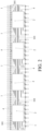
- FIG. 1 is an exemplary schematic structural diagram of a sampling device according to an embodiment of the present disclosure.
- the sampling device includes an auxiliary function region 1, two core function regions 2, and a terminal connector 4.
- the sampling device is connected to a battery 3 through the terminal connector 4.
- Two core function regions 2 are arranged in the auxiliary function region 1.
- the two core function regions 2 are cascaded through wiring of the auxiliary function region 1. It should be noted that only two batteries 3 are exemplarily shown in FIG. 1 .
- a battery module includes multiple batteries, and each battery 3 is connected to the sampling device by using the terminal connector 4.
- the auxiliary function region 1 has a lead-out terminal.
- the terminal connector 4 is electrically connected to the lead-out terminal of the auxiliary function region 1, or the lead-out terminal of the auxiliary function region 1 is the terminal connector 4.
- the terminal connector 4 is made of a metal material.
- the multiple core function regions 2 and the auxiliary function region 1 may be integrally arranged. In this arrangement, the multiple core function regions 2 are integrated in the auxiliary function region 1. Alternatively, the multiple core function regions 2 and the auxiliary function region 1 may be independently arranged. In this arrangement, the multiple core function regions 2 are arranged on the auxiliary function region 1.
- the core function regions 2 and the auxiliary function region 1 are flexible printed circuit (FPC) boards or printed circuit boards (PCBs). Specifically, the following three cases exist.
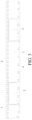
- FIG. 2 is an exemplary schematic structural diagram in which four core function regions 2 and an auxiliary function region 1 are integrally arranged according to an embodiment of the present disclosure.
- the components (not shown in FIG. 2 ) of each core function region 2 use the FPC board as a carrier board
- the auxiliary function region 1 also adopts the FPC board
- the terminal connector 4 is connected to the battery by using a lead-out portion of the FPC board.
- the terminal connector 4 is substantially included in the auxiliary function region 1. Since the components of each core function region 2 use the FPC board as the carrier board, and cascade between the core function regions 2 is implemented by a flexible circuit 101, the multiple core function regions 2 can be integrally formed with the auxiliary function region 1 and the terminal connector 4.
- a nickel piece may be further soldered at a joint of the FPC board and the battery 3.
- the FPC board is connected to the battery 3 by using the nickel piece as the terminal connector 4.
- FIG. 3 is an exemplary schematic structural diagram in which two core function regions 2 and an auxiliary function region 1 are PCBs according to an embodiment of the present disclosure.
- each core function region 2 adopts the PCB.
- the auxiliary function region 1 adopts a single-layer PCB, and the terminal connector 4 is connected to the battery by using a nickel piece of the PCB.
- this structure does not replace an existing conventional connection manner of nickel piece soldering for a battery end, an internal circuit of the single-layer PCB replaces the conventional wire harness, which overall replaces the current solution of realizing cascading by using a wire harness and a connector.
- this structure Compared with the current cascading solution, costs and a space of the wire harness and the connector are reduced, which can reduce a physical area of the PCB, thereby indirectly reducing costs and a volume of a collection device.
- this structure has lower costs than the foregoing structure that uses the FPC board.
- this structure occupies a larger space and has a specific requirement on a space shape.
- the wiring is a flexible circuit of the FPC board, and the multiple core function regions 2 are cascaded by using the flexible circuit.
- the wiring is an internal circuit of the PCB, and the multiple core function regions 2 are cascaded by using the internal circuit.
- the lead-out portion of the flexible circuit inside the FPC board may include a copper foil, an aluminum foil, a copper nickel strip, an aluminum nickel strip, or a nickel strip. If the auxiliary function region adopts the PCB, the terminal connector is configured to connect to the battery by using the nickel piece of the PCB.
- the flexible circuit includes a flexible etched circuit (FEC) or a flexible die-cutting circuit (FDC).
- the multiple core function regions 2 are arranged on the auxiliary function region 1.
- the core function regions 2 are FPC boards, and the auxiliary function region 1 is a PCB.
- the core function regions 2 are PCBs, and the auxiliary function region is an FPC board.
- a position on the auxiliary function region 1 corresponding to each core function region 2 is hollowed out; and the core function region 2 is arranged at the hollowed-out position and is electrically connected to the auxiliary function region.
- Arranging the hollowed-out position in the auxiliary function region 1 can further reduce manufacturing costs of the sampling device.
- the core function region 2 is arranged at the hollowed-out position, a heat dissipation effect of the components in the core function region 2 is further improved, thereby improving efficiency of the components in the core function region 2.
- the core function region 2 needs to be arranged on the auxiliary function region 1, an area of the hollowed-out position needs to be less than an area of the core function region 2, to realize stable and firm connection of the core function region 2. It may be understood that, in another embodiment of the present disclosure, the core function region 2 may be directly arranged on the auxiliary function region 1 without arranging the hollowed-out position on the auxiliary function region 1.
- each connecting portion is electrically connected to the wiring in the auxiliary function region 1.
- the connecting portion is arranged at the edge of the core function region 2 to connect to the wiring in the auxiliary function region 1 more desirably, thereby ensuring connection reliability.
- the connecting portion is a connecting half-hole.
- the wiring includes at least one cascade circuit and multiple battery circuits.
- a first end of each battery circuit is electrically connected to the corresponding connecting portion.
- a second end of each battery circuit is electrically connected to the battery.
- Two ends of the at least one cascade circuit are respectively electrically connected to corresponding connecting portions on two adjacent core function regions 2.
- FIG. 4 is an exemplary schematic diagram in which two core function regions 2 and an auxiliary function region 1 are independently arranged according to an embodiment of the present disclosure.
- each core function region 2 does not use the FPC board as a carrier board, but uses the PCB as a carrier board.
- the auxiliary function region 1 adopts the FPC board, cascading between the core function regions 2 is still realized by the flexible circuit.
- the terminal connector 4 is connected to the battery by using the lead-out portion of the FPC board. In this arrangement, the terminal connector 4 is substantially included in the auxiliary function region 1.
- each core function region 2 adopts the PCB, the multiple core function regions 2 cannot be integrally formed with the auxiliary function region 1 and the terminal connector 4, and can only be separately arranged.
- the existing conventional connection manner of nickel piece soldering is replaced for the battery end.
- the two arrangements simplify a manufacturing process of the auxiliary function region 2, greatly reduce costs for the nickel piece, and resolve a problem regarding a position and a flatness of the nickel piece.
- the multiple core function regions are directly cascaded with each other by using the wiring of the auxiliary function region.
- the auxiliary function region replaces the traditional wire harness, which replaces the current solution of realizing cascading by using a wire harness and a connector. Therefore, problems that an impedance of the sampling device increases and a probability of failure increases caused by a large number of wire harness connection links do not exist.
- integration efficiency of the core function region is improved, an area of a main carrier board in the region with high costs is reduced, and costs are reduced.
- the core function region may be standardized to reduce development costs and cycles.
- auxiliary function region may be expanded as needed to form multiple core function regions connected to each other, to reduce connection wire harnesses and inserts between conventional PCBs, thereby simplifying a design, reducing costs, and improving reliability.
- the auxiliary function region cascades the core function region.
- One mounting corresponds to multiple battery sampling devices, so that collection devices do not need to be mounted one by one, thereby reducing a mounting time, realizing efficient mounting, facilitating mounting, and avoiding a risk of erroneously inserting a wire harness.
- the auxiliary function region adopts the FPC board, the manufacturing process of the auxiliary function region is further simplified, costs for the nickel piece are greatly reduced, and the problem regarding the position and the flatness of the nickel piece is resolved.
- the terminal connector may be implemented in multiple manners, which is compatible with multiple battery system designs.
- the auxiliary function region adopts the FPC board
- the core function region adopts the PCB
- the terminal connector adopts the nickel piece.
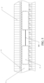
- FIG. 5 is a partial schematic structural diagram of a sampling device in which an auxiliary function region adopts, for example, an FPC board and a core function region adopts, for example, a PCB according to an embodiment of the present disclosure.
- An FPC board 1 is connected to the battery 3.
- Two PCBs 2 are arranged on the FPC board 1. The two PCBs 2 are cascaded by using a flexible circuit 100 of the FPC board 1.
- one FPC board 1 may be used, and multiple PCBs 2 are arranged thereon.
- a quantity of the PCBs 2 is determined based on a quantity of batteries in a battery module.
- the FPC board 1 Based on an arrangement requirement of the PCBs, the FPC board 1 needs to be hollowed out. Therefore, a position on the FPC board 1 corresponding to an arrangement position of each PCB 2 is hollowed out.
- the FPC board 1 is connected to the multiple PCBs 2 through soldering.
- a circuit of the FPC board 1 includes multiple circuits.
- An edge of each PCB 2 is provided with multiple half-holes.
- the multiple half-holes include connecting half-holes.
- the PCBs 2 are soldered to corresponding circuits through respective connecting half-holes.
- Each connecting half-hole corresponds to a circuit.
- the multiple circuits include at least one cascade circuit and multiple battery circuits.
- a first end of each battery circuit is soldered to the corresponding connecting half-hole.
- a second end of each battery circuit is soldered to the battery 3.
- a specific method for soldering to the battery is as follows: The second end of each battery circuit has a nickel piece 4 (shown in FIG. 5 ) soldered thereto. The second end of each battery circuit is soldered to the battery 3 through the nickel piece 4.
- a circuit 100 in FIG. 5 is a cascade circuit. Two ends of the circuit 100 are respectively soldered to the corresponding connecting half-holes on the two cascaded PCBs 2.
- one cascade circuit may be required, or multiple cascade circuits may be required. A quantity of cascade circuits needs to be determined according to an actual requirement.
- FIG. 6 is a schematic diagram of connection between a single PCB 2 and an FPC board 1 according to an embodiment of the present disclosure. Similarly, although only a connection relationship between key devices is shown in FIG. 2 , it does not mean that the sampling device is consists of only the devices.
- multiple half-holes 2011 are provided on an edge of the PCB 2.
- a pad 2012 usually needs to be arranged on the corresponding circuit.
- a half-hole solder joint 201 is formed.
- the half-hole solder joint 201 realizes sampling of parameters of the battery 3 by the PCB 2 through a circuit 200 (it is assumed that the circuit 200 is a battery circuit).
- the half-hole solder joint 201 realizes the cascading of the PCB 2 to another PCB 2 through the circuit 200 (it is assumed that the circuit 200 is a cascade circuit).
- the multiple half-holes on the PCB 2 further include a spare half-hole.
- the spare half-hole may be soldered to a corresponding circuit.
- the spare half-hole is not connected to the corresponding circuit.
- the spare half-hole is reserved for expanding functions of the PCB 2 in the future, and may be soldered to the corresponding circuit first for standby application.
- the spare half-hole may not be connected to the corresponding circuit, and may be soldered when needed.
- FIG. 7 is a schematic structural diagram of a battery and a pole structure thereof according to an embodiment of the present disclosure.
- FIG. 7 exemplarily shows four batteries 3.
- a pole 5 and a pole 6 exist on each battery 3.
- the poles 6 of each two batteries 3 are connected through a copper bar 7.
- the pole 5 needs to be separately soldered to the nickel piece 4. Since the pole 6 is connected to the pole 6 of another battery through the copper bar 7, only the copper bar 7 needs to be soldered to the nickel piece 4, without a need to solder one nickel piece 4 to each pole 6, which reduces a quantity of nickel piece 4 and corresponding circuits, thereby indirectly reducing soldering complexity and a soldering quantity.
- the connection manner between the nickel piece 4 and the battery may be further embodied through FIG. 5 .
- nickel pieces 4 are soldered to the battery 3 with a housing of a core of the battery being charged. If the housing of the core of the battery is not charged, one of the pole 5 and the pole 6 of each battery needs to be soldered to the nickel piece 4.
- FIG. 8 is an exploded view of a sampling device formed by two PCBs and an FPC board according to an embodiment of the present disclosure.
- FIG. 8 clearly shows that a corresponding position on the FPC board 1 for arranging the PCB 2 is hollowed out, and multiple half-holes 2011 are provided on an edge of the PCB 2.
- FIG. 8 exemplarily shows multiple battery circuits 300 and multiple cascade circuits 400.
- an upper surface and a lower surface of the FPC board 1 each need to be covered with a layer of film, that is, are respectively covered with an upper cover film 8 and a lower cover film 9.
- the upper cover film 8 has openings corresponding to the solder joints of the connecting half-holes.
- the lower cover film 9 has openings corresponding to solder joints between the nickel pieces 4 and the battery 3 has an opening.
- solder points are relatively dense, a specific flatness needs to be ensured.
- a reinforcing sheet 10 is further required. In this way, the multiple PCBs 2 can be cascaded, and the multiple PCBs 2 can sample the parameters of the battery 3 through the FPC board 1.
- the foregoing sampling device using the FPC board as a substrate is mainly applied to vehicles that use electric energy as an energy source (including pure electric vehicles and hybrid vehicles). For sampling of battery parameters of these vehicles, due to a limited battery mounting space, a minimized space ratio is required while a sampling function and sampling accuracy are ensured.
- the sampling device using the FPC board as the auxiliary function region effectively resolves the requirement.
- the sampling device using the FPC board as the auxiliary function region and the FPC board as the carrier board of the core function region is an optimal solution.
- the proposed sampling device can be further applied to other similar devices or products with a relatively small space, which has wide applicability.
- a hard plate may be used as a substrate to form the sampling device.
- the PCB is used as the substrate to form the sampling device.
- a large PCB may be used as the substrate, and multiple small PCBs are arranged on the large PCB. Connection manners of rest devices are the same as those in the foregoing sampling device that uses the FPC board as the substrate. Details are not described herein.
- an embodiment of the present disclosure further provides a battery management system.
- the battery management system includes a battery management controller and any of the foregoing sampling device.
- a connecting insert is arranged on the sampling device.
- the sampling device is electrically connected to the battery management controller through the connecting insert.
- FIG. 9 is a schematic structural diagram of a battery management system according to an embodiment of the present disclosure.
- a first core function region that is, CFA1
- a last core function region that is, CFAN
- the wire harness connector 11 is configured for insertion and connection of a wire harness 15.
- the first core function region and the last core function region are connected to the battery management controller 12 through respective wire harness connectors 11 and wire harnesses 15.
- the battery management controller 12 is located inside a power distribution box 13.
- the battery management controller 12 is connected to a vehicle controller 14.
- the battery management controller 12 is configured to receive and process a signal transmitted by the sampling device, and transmit the processed signal to the vehicle controller 14.
- the vehicle controller 14 may perform further processing based on the received signal.
- an embodiment of the present disclosure further provides a battery pack.
- the battery pack includes any of the foregoing sampling devices.
- an embodiment of the present disclosure further provides a vehicle.
- the vehicle includes any of the foregoing sampling devices.
- the auxiliary function region replaces the traditional wire harness, which replaces the current solution of realizing cascading by using a wire harness and a connector. Therefore, problems that an impedance of the sampling device increases and a probability of failure increases caused by a large number of wire harness connection links do not exist.
- integration efficiency of the core function region is improved, an area of a main carrier board in the region with high costs is reduced, and costs are reduced.
- the core function region may be standardized to reduce development costs and cycles.
- auxiliary function region may be expanded as needed to form multiple core function regions connected to each other, to reduce connection wire harnesses and inserts between conventional PCBs, thereby simplifying a design, reducing costs, and improving reliability.
- the auxiliary function region cascades the core function region.
- One mounting corresponds to multiple battery sampling devices, so that collection devices do not need to be mounted one by one, thereby reducing a mounting time, realizing efficient mounting, facilitating mounting, and avoiding a risk of erroneously inserting a wire harness.
- the auxiliary function region 2 adopts the FPC board, a manufacturing process of the auxiliary function region 2 is further simplified, costs for the nickel piece are greatly reduced, and a problem regarding a position and a flatness of the nickel piece is resolved.
- the terminal connector may be implemented in multiple manners, which is compatible with multiple battery system designs, and has high practicability.
Landscapes
- Engineering & Computer Science (AREA)
- General Chemical & Material Sciences (AREA)
- Chemical & Material Sciences (AREA)
- Chemical Kinetics & Catalysis (AREA)
- Electrochemistry (AREA)
- Manufacturing & Machinery (AREA)
- Power Engineering (AREA)
- Mechanical Engineering (AREA)
- Microelectronics & Electronic Packaging (AREA)
- Life Sciences & Earth Sciences (AREA)
- Sustainable Development (AREA)
- Sustainable Energy (AREA)
- Transportation (AREA)
- Physics & Mathematics (AREA)
- General Physics & Mathematics (AREA)
- Battery Mounting, Suspending (AREA)
- Secondary Cells (AREA)
- Connection Of Batteries Or Terminals (AREA)
- Insulated Conductors (AREA)
Abstract
Description
- The present disclosure claims priority to
Chinese Patent Application No. 2021226411072, filed on October 29, 2021 Chinese Patent Application No. 202220343039.3, filed on February 18, 2022 - The present disclosure relates to the technical field of batteries, and more specifically, to a sampling device, a battery management system, and a vehicle.
- At present, new energy vehicles become the frontier science of current automotive technology development, and electric vehicles gradually become an important direction that replaces conventional fuel vehicles. A battery module functions as a "heart" of the electric vehicles, and management of the battery module is realized through a battery management system. A collection module is an important component of the battery management system, which is configured to collect information such as a single voltage, a total voltage, a current, and a temperature. Reliability of a collector is of great significance.
- In many existing battery modules, information such as a voltage, a current, and a temperature is collected by using a wire harness. Using the wire harness to connect the collector to the battery module results in a larger number of connection links, which increases an impedance and a probability of failure. In addition, since the wire harness needs to be connected to a printed circuit board (PCB) by using a connector, risks caused by poor soldering between the connector and the PCB, breakage of the wire harness, and the like also exist.
- Although an idea of using a flexible flat cable (FFC) instead of the wire harness to realize connection with the battery module is proposed, for the PCB, especially cascade of multiple PCBs, the wire harness and the connector are still used. However, the risks caused by poor soldering between the connector and the PCB, breakage of the wire harness, and the like still exist. In addition, since the connector exists, a physical area of the PCB cannot be reduced, which indirectly increases costs and a volume of the collection module.
- In view of the foregoing problems, the present disclosure provides a sampling device, a battery management system, a battery pack, and a vehicle, to resolve or partially resolve the foregoing problems.
- According to a first aspect, a sampling device is provided. The sampling device includes multiple core function regions, an auxiliary function region, and a terminal connector.
- The multiple core function regions are configured to process information of a battery.
- The auxiliary function region has wiring arranged therein, and is configured to transmit a signal corresponding to the battery information. The multiple core function regions are cascaded through the wiring.
- The terminal connector is configured to connect the battery and the auxiliary function region to collect the battery information.
- Optionally, the auxiliary function region has a lead-out terminal. The terminal connector is electrically connected to the lead-out terminal of the auxiliary function region, or the lead-out terminal of the auxiliary function region is the terminal connector.
- Optionally, the terminal connector is made of a metal material.
- Optionally, the multiple core function regions and the auxiliary function region are integrally arranged. The multiple core function regions are integrated in the auxiliary function region.
- Optionally, the core function regions and the auxiliary function region are flexible printed circuit (FPC) boards or printed circuit boards (PCBs).
- Optionally, the multiple core function regions and the auxiliary function region are independently arranged. The multiple core function regions are arranged on the auxiliary function region.
- Optionally, the core function regions are FPC boards, and the auxiliary function region is a PCB; or
the core function regions are PCBs; and the auxiliary function region is an FPC board. - Optionally, a position on the auxiliary function region corresponding to each core function region is hollowed out. The core function region is arranged at the hollowed-out position and is electrically connected to the auxiliary function region.
- Optionally, an area of the hollowed-out position is less than an area of each core function region.
- Optionally, multiple connecting portions are arranged at an edge of each core function region.
- Each connecting portion is electrically connected to the wiring in the auxiliary function region.
- Optionally, the wiring includes at least one cascade circuit and multiple battery circuits.
- A first end of each battery circuit is electrically connected to the corresponding connecting portion. A second end of each battery circuit is electrically connected to the battery.
- Two ends of the at least one cascade circuit are respectively electrically connected to corresponding connecting portions on two adjacent core function regions.
- Optionally, the connecting portion is a connecting half-hole.
- Optionally, the second end of each battery circuit has a nickel piece soldered thereto. The second end of each battery circuit is soldered to the battery through the nickel piece.
- According to a second aspect, a battery management system is provided. The battery management system includes a battery management controller and the sampling device in any implementation of the first aspect. A connecting insert is arranged on the sampling device. The sampling device is electrically connected to the battery management controller through the connecting insert.
- Optionally, the connecting insert includes a wire harness connector. In the multiple cascaded core function regions, a first core function region and a last core function region each have the wire harness connector arranged thereon. The wire harness connector is configured for insertion and connection of a wire harness. The first core function region and the last core function region are connected to the battery management controller through respective wire harness connectors and wire harnesses.
- Optionally, the battery management controller is connected to a vehicle controller. The battery management controller is configured to receive and process a signal transmitted by the sampling device, and transmit the processed signal to the vehicle controller.
- According to a third aspect, a battery pack is provided, which includes the sampling device in any implementation of the first aspect.
- According to a fourth aspect, a vehicle is provided. The vehicle includes the sampling device in any implementation of the first aspect.
- The embodiments of the present disclosure have the following advantages.
- In the present disclosure, the multiple core function regions are configured to process information of the battery, the auxiliary function region has the wiring arranged therein, and is configured to transmit the signal corresponding to the information, the multiple core function regions are cascaded through the wiring of the auxiliary function region, and the terminal connector is configured to connect the battery and the auxiliary function region. In this way, the multiple core function regions can sample and obtain the information and parameters of the battery through the auxiliary function region and the terminal connector. Since a conventional wire harness is replaced with the auxiliary function region, problems that an impedance of the sampling device increases and a probability of failure increases caused by a large number of wire harness connection links do not exist.
- The multiple core function regions are directly cascaded by using the wiring of the auxiliary function region, which replaces a current solution of realizing cascading by using a wire harness and a connector, thereby avoiding risks caused by poor soldering between the connector and the PCB, breakage of the wire harness, and the like still exist. In addition, since no connector exists, a physical area of the PCB can be reduced, which indirectly reduces costs and a volume of the collection device, and has high practicality.
- Various other advantages and benefits become clear to a person of ordinary skill in the art by reading the following detailed description of preferred implementations. The drawings are merely used for showing the preferred implementations, and cannot be construed as a limitation on the present disclosure. Throughout the drawings, same reference numerals are used to represent same components. In the drawings:
-
FIG. 1 is a schematic structural diagram of a sampling device according to an embodiment of the present disclosure. -
FIG. 2 is a schematic structural diagram in which fourcore function regions 2 and anauxiliary function region 1 are integrally arranged according to an embodiment of the present disclosure. -
FIG. 3 is a schematic structural diagram in which twocore function regions 2 and anauxiliary function region 1 are printed circuit boards (PCBs) according to an embodiment of the present disclosure. -
FIG. 4 is a schematic diagram in which twocore function regions 2 and anauxiliary function region 1 are independently arranged according to an embodiment of the present disclosure. -
FIG. 5 is a partial schematic structural diagram of a sampling device in which an auxiliary function region adopts, for example, a flexible printed circuit (FPC) board and a core function region adopts, for example, a PCB according to an embodiment of the present disclosure. -
FIG. 6 is a schematic diagram of connection between a single PCB and an FPC board according to an embodiment of the present disclosure. -
FIG. 7 is a schematic structural diagram of a battery and a pole structure thereof according to an embodiment of the present disclosure. -
FIG. 8 is an exploded view of a sampling device formed by two PCBs and an FPC board according to an embodiment of the present disclosure. -
FIG. 9 is a schematic structural diagram of a battery management system according to an embodiment of the present disclosure. - To make the foregoing objectives, features, and advantages of the present disclosure clearer and easier to understand, the present disclosure is described in further detail below with reference to drawings and specific implementations. It should be understood that the specific embodiments described herein are merely used for explaining the present disclosure, and are only some rather than all of the embodiments of the present disclosure, and are not used for limiting the present disclosure.
- An embodiment of the present disclosure provides a sampling device. The sampling device includes multiple core function regions, an auxiliary function region, and a terminal connector. The multiple core function regions are configured to process information of a battery. The auxiliary function region has wiring arranged therein, and is configured to transmit a signal corresponding to the information. The terminal connector is configured to connect the battery and the auxiliary function region, so that the multiple core function regions can obtain the information and parameters of the battery through the auxiliary function region and the terminal connector, and then process the information of the battery to equalize the battery. In addition, the multiple core function regions are cascaded by using the wiring of the auxiliary function region, which implements cascading between the multiple core function regions without using a wire harness and a connector currently used.
-
FIG. 1 is an exemplary schematic structural diagram of a sampling device according to an embodiment of the present disclosure. The sampling device includes anauxiliary function region 1, twocore function regions 2, and aterminal connector 4. The sampling device is connected to abattery 3 through theterminal connector 4. Twocore function regions 2 are arranged in theauxiliary function region 1. The twocore function regions 2 are cascaded through wiring of theauxiliary function region 1. It should be noted that only twobatteries 3 are exemplarily shown inFIG. 1 . In a practical application, a battery module includes multiple batteries, and eachbattery 3 is connected to the sampling device by using theterminal connector 4. - The
auxiliary function region 1 has a lead-out terminal. Theterminal connector 4 is electrically connected to the lead-out terminal of theauxiliary function region 1, or the lead-out terminal of theauxiliary function region 1 is theterminal connector 4. Preferably, theterminal connector 4 is made of a metal material. - In this embodiment of the present disclosure, the multiple
core function regions 2 and theauxiliary function region 1 may be integrally arranged. In this arrangement, the multiplecore function regions 2 are integrated in theauxiliary function region 1. Alternatively, the multiplecore function regions 2 and theauxiliary function region 1 may be independently arranged. In this arrangement, the multiplecore function regions 2 are arranged on theauxiliary function region 1. - For the integral arrangement, the
core function regions 2 and theauxiliary function region 1 are flexible printed circuit (FPC) boards or printed circuit boards (PCBs). Specifically, the following three cases exist. - 1). The
auxiliary function region 1 adopts the FPC board, and components of each of the multiplecore function regions 2 use the FPC board as a carrier board. In other words, the multiplecore function regions 2 and theauxiliary function region 1 are manufactured by using the same FPC board. - 2). The
auxiliary function region 1 adopts the PCB, and each of thecore function regions 2 adopts the PCB. In other words, the multiplecore function regions 2 and theauxiliary function region 1 are manufactured by using the PCB. Similar to the manner 1), a large PCB is used as theauxiliary function region 1, and the components of each core function region use the PCB as a carrier board. Alternatively, a large single-layer PCB is used as theauxiliary function region 1, and a small PCB is separately manufactured on each core function region, and then is soldered to the large single-layer PCB. Certainly, the latter process is slightly more complex than the former process, but has a cost advantage. - 3). The
auxiliary function region 1 adopts the FPC board, and each of thecore function regions 2 adopts the PCB. Since the FPC board needs to be wrapped with a cover film, after each core function region is soldered to the FPC board, the PCB is wrapped by using the cover film, so that the multiplecore function regions 2 and theauxiliary function regions 1 are integrally arranged. -
FIG. 2 is an exemplary schematic structural diagram in which fourcore function regions 2 and anauxiliary function region 1 are integrally arranged according to an embodiment of the present disclosure. InFIG. 2 , the components (not shown inFIG. 2 ) of eachcore function region 2 use the FPC board as a carrier board, theauxiliary function region 1 also adopts the FPC board, and theterminal connector 4 is connected to the battery by using a lead-out portion of the FPC board. In this arrangement, theterminal connector 4 is substantially included in theauxiliary function region 1. Since the components of eachcore function region 2 use the FPC board as the carrier board, and cascade between thecore function regions 2 is implemented by aflexible circuit 101, the multiplecore function regions 2 can be integrally formed with theauxiliary function region 1 and theterminal connector 4. - In addition, it should be noted that a nickel piece may be further soldered at a joint of the FPC board and the
battery 3. The FPC board is connected to thebattery 3 by using the nickel piece as theterminal connector 4. -
FIG. 3 is an exemplary schematic structural diagram in which twocore function regions 2 and anauxiliary function region 1 are PCBs according to an embodiment of the present disclosure. InFIG. 3 , eachcore function region 2 adopts the PCB. In addition, theauxiliary function region 1 adopts a single-layer PCB, and theterminal connector 4 is connected to the battery by using a nickel piece of the PCB. Although this structure does not replace an existing conventional connection manner of nickel piece soldering for a battery end, an internal circuit of the single-layer PCB replaces the conventional wire harness, which overall replaces the current solution of realizing cascading by using a wire harness and a connector. Compared with the current cascading solution, costs and a space of the wire harness and the connector are reduced, which can reduce a physical area of the PCB, thereby indirectly reducing costs and a volume of a collection device. In addition, this structure has lower costs than the foregoing structure that uses the FPC board. However, compared with the structure that uses the FPC board, this structure occupies a larger space and has a specific requirement on a space shape. - In this embodiment of the present disclosure, if the
auxiliary function region 1 adopts the FPC board, the wiring is a flexible circuit of the FPC board, and the multiplecore function regions 2 are cascaded by using the flexible circuit. If theauxiliary function region 1 adopts the PCB, the wiring is an internal circuit of the PCB, and the multiplecore function regions 2 are cascaded by using the internal circuit. - The lead-out portion of the flexible circuit inside the FPC board may include a copper foil, an aluminum foil, a copper nickel strip, an aluminum nickel strip, or a nickel strip. If the auxiliary function region adopts the PCB, the terminal connector is configured to connect to the battery by using the nickel piece of the PCB. The flexible circuit includes a flexible etched circuit (FEC) or a flexible die-cutting circuit (FDC).
- For the independent arrangement, the multiple
core function regions 2 are arranged on theauxiliary function region 1. Thecore function regions 2 are FPC boards, and theauxiliary function region 1 is a PCB. Alternatively, thecore function regions 2 are PCBs, and the auxiliary function region is an FPC board. - In the independent arrangement, a position on the
auxiliary function region 1 corresponding to eachcore function region 2 is hollowed out; and thecore function region 2 is arranged at the hollowed-out position and is electrically connected to the auxiliary function region. Arranging the hollowed-out position in theauxiliary function region 1 can further reduce manufacturing costs of the sampling device. In addition, since thecore function region 2 is arranged at the hollowed-out position, a heat dissipation effect of the components in thecore function region 2 is further improved, thereby improving efficiency of the components in thecore function region 2. Further, since thecore function region 2 needs to be arranged on theauxiliary function region 1, an area of the hollowed-out position needs to be less than an area of thecore function region 2, to realize stable and firm connection of thecore function region 2. It may be understood that, in another embodiment of the present disclosure, thecore function region 2 may be directly arranged on theauxiliary function region 1 without arranging the hollowed-out position on theauxiliary function region 1. - Furthermore, multiple connecting portions are arranged at an edge of each
core function region 2. Each connecting portion is electrically connected to the wiring in theauxiliary function region 1. The connecting portion is arranged at the edge of thecore function region 2 to connect to the wiring in theauxiliary function region 1 more desirably, thereby ensuring connection reliability. In a preferred embodiment, the connecting portion is a connecting half-hole. - For the specific connection, the wiring includes at least one cascade circuit and multiple battery circuits. A first end of each battery circuit is electrically connected to the corresponding connecting portion. A second end of each battery circuit is electrically connected to the battery. Two ends of the at least one cascade circuit are respectively electrically connected to corresponding connecting portions on two adjacent
core function regions 2. For a specific manner in which the second end of each battery circuit is electrically connected to the battery, reference may be made to the foregoing description. -
FIG. 4 is an exemplary schematic diagram in which twocore function regions 2 and anauxiliary function region 1 are independently arranged according to an embodiment of the present disclosure. InFIG. 4 , eachcore function region 2 does not use the FPC board as a carrier board, but uses the PCB as a carrier board. In addition, since theauxiliary function region 1 adopts the FPC board, cascading between thecore function regions 2 is still realized by the flexible circuit. Theterminal connector 4 is connected to the battery by using the lead-out portion of the FPC board. In this arrangement, theterminal connector 4 is substantially included in theauxiliary function region 1. However, since eachcore function region 2 adopts the PCB, the multiplecore function regions 2 cannot be integrally formed with theauxiliary function region 1 and theterminal connector 4, and can only be separately arranged. However, the existing conventional connection manner of nickel piece soldering is replaced for the battery end. The two arrangements simplify a manufacturing process of theauxiliary function region 2, greatly reduce costs for the nickel piece, and resolve a problem regarding a position and a flatness of the nickel piece. - Based on the above, in the present disclosure, the multiple core function regions are directly cascaded with each other by using the wiring of the auxiliary function region. The auxiliary function region replaces the traditional wire harness, which replaces the current solution of realizing cascading by using a wire harness and a connector. Therefore, problems that an impedance of the sampling device increases and a probability of failure increases caused by a large number of wire harness connection links do not exist. In addition, integration efficiency of the core function region is improved, an area of a main carrier board in the region with high costs is reduced, and costs are reduced. The core function region may be standardized to reduce development costs and cycles.
- Moreover, the risks caused by poor soldering between the connector and the PCB, breakage of the wire harness, and the like are avoided. In addition, since the connector does not exist, the physical area of the PCB can be reduced, which indirectly reduces the costs and the volume of the collection device. The auxiliary function region may be expanded as needed to form multiple core function regions connected to each other, to reduce connection wire harnesses and inserts between conventional PCBs, thereby simplifying a design, reducing costs, and improving reliability.
- In addition, a process of manually inserting and connecting a communication wire harness is canceled. The auxiliary function region cascades the core function region. One mounting corresponds to multiple battery sampling devices, so that collection devices do not need to be mounted one by one, thereby reducing a mounting time, realizing efficient mounting, facilitating mounting, and avoiding a risk of erroneously inserting a wire harness. If the auxiliary function region adopts the FPC board, the manufacturing process of the auxiliary function region is further simplified, costs for the nickel piece are greatly reduced, and the problem regarding the position and the flatness of the nickel piece is resolved. In addition, the terminal connector may be implemented in multiple manners, which is compatible with multiple battery system designs.
- To more clearly explain and describe the sampling device of the present disclosure, a description is provided below by using an example in which the auxiliary function region adopts the FPC board, the core function region adopts the PCB, and the terminal connector adopts the nickel piece.
-
FIG. 5 is a partial schematic structural diagram of a sampling device in which an auxiliary function region adopts, for example, an FPC board and a core function region adopts, for example, a PCB according to an embodiment of the present disclosure. AnFPC board 1 is connected to thebattery 3. TwoPCBs 2 are arranged on theFPC board 1. The twoPCBs 2 are cascaded by using aflexible circuit 100 of theFPC board 1. - It should be noted that, in an actual sampling device, one
FPC board 1 may be used, andmultiple PCBs 2 are arranged thereon. A quantity of thePCBs 2 is determined based on a quantity of batteries in a battery module. - Based on an arrangement requirement of the PCBs, the
FPC board 1 needs to be hollowed out. Therefore, a position on theFPC board 1 corresponding to an arrangement position of eachPCB 2 is hollowed out. TheFPC board 1 is connected to themultiple PCBs 2 through soldering. - Specifically, a circuit of the
FPC board 1 includes multiple circuits. An edge of eachPCB 2 is provided with multiple half-holes. The multiple half-holes include connecting half-holes. ThePCBs 2 are soldered to corresponding circuits through respective connecting half-holes. Each connecting half-hole corresponds to a circuit. - The multiple circuits include at least one cascade circuit and multiple battery circuits. A first end of each battery circuit is soldered to the corresponding connecting half-hole. A second end of each battery circuit is soldered to the
battery 3. A specific method for soldering to the battery is as follows: The second end of each battery circuit has a nickel piece 4 (shown inFIG. 5 ) soldered thereto. The second end of each battery circuit is soldered to thebattery 3 through thenickel piece 4. - Two ends of the at least one cascade circuit are respectively soldered to the corresponding connecting half-holes on the two cascaded
PCBs 2. For example, acircuit 100 inFIG. 5 is a cascade circuit. Two ends of thecircuit 100 are respectively soldered to the corresponding connecting half-holes on the two cascadedPCBs 2. Certainly, according to an actual requirement, during cascading of the PCB, one cascade circuit may be required, or multiple cascade circuits may be required. A quantity of cascade circuits needs to be determined according to an actual requirement. -
FIG. 6 is a schematic diagram of connection between asingle PCB 2 and anFPC board 1 according to an embodiment of the present disclosure. Similarly, although only a connection relationship between key devices is shown inFIG. 2 , it does not mean that the sampling device is consists of only the devices. - In
FIG. 6 , multiple half-holes 2011 are provided on an edge of thePCB 2. To solder each half-hole 2011 to a corresponding circuit, apad 2012 usually needs to be arranged on the corresponding circuit. After the two are soldered together by using solder, a half-hole solder joint 201 is formed. The half-hole solder joint 201 realizes sampling of parameters of thebattery 3 by thePCB 2 through a circuit 200 (it is assumed that thecircuit 200 is a battery circuit). Alternatively, the half-hole solder joint 201 realizes the cascading of thePCB 2 to anotherPCB 2 through the circuit 200 (it is assumed that thecircuit 200 is a cascade circuit). In addition, the multiple half-holes on thePCB 2 further include a spare half-hole. The spare half-hole may be soldered to a corresponding circuit. Alternatively, the spare half-hole is not connected to the corresponding circuit. In other words, the spare half-hole is reserved for expanding functions of thePCB 2 in the future, and may be soldered to the corresponding circuit first for standby application. Alternatively, the spare half-hole may not be connected to the corresponding circuit, and may be soldered when needed. - For the connection between the
nickel piece 4 and the battery, comprehensive reference may be made toFIG. 5 andFIG. 7. FIG. 7 is a schematic structural diagram of a battery and a pole structure thereof according to an embodiment of the present disclosure.FIG. 7 exemplarily shows fourbatteries 3. Apole 5 and a pole 6 exist on eachbattery 3. The poles 6 of each twobatteries 3 are connected through acopper bar 7. - During soldering of the
nickel piece 4 shown inFIG. 5 andFIG. 7 to thebattery 3, for each battery, thepole 5 needs to be separately soldered to thenickel piece 4. Since the pole 6 is connected to the pole 6 of another battery through thecopper bar 7, only thecopper bar 7 needs to be soldered to thenickel piece 4, without a need to solder onenickel piece 4 to each pole 6, which reduces a quantity ofnickel piece 4 and corresponding circuits, thereby indirectly reducing soldering complexity and a soldering quantity. The connection manner between thenickel piece 4 and the battery may be further embodied throughFIG. 5 . An upper row of nickel pieces are separately soldered to thepoles 5 of the batteries, and a lower row of nickel pieces are soldered to the copper bars 7, which do not need to be separately soldered to the poles 6 of the batteries. It should be noted that, thenickel pieces 4 are soldered to thebattery 3 with a housing of a core of the battery being charged. If the housing of the core of the battery is not charged, one of thepole 5 and the pole 6 of each battery needs to be soldered to thenickel piece 4. - To describe the sampling device more clearly,
FIG. 8 is an exploded view of a sampling device formed by two PCBs and an FPC board according to an embodiment of the present disclosure.FIG. 8 clearly shows that a corresponding position on theFPC board 1 for arranging thePCB 2 is hollowed out, and multiple half-holes 2011 are provided on an edge of thePCB 2.FIG. 8 exemplarily showsmultiple battery circuits 300 andmultiple cascade circuits 400. - To protect the
FPC board 1, an upper surface and a lower surface of theFPC board 1 each need to be covered with a layer of film, that is, are respectively covered with an upper cover film 8 and a lower cover film 9. The upper cover film 8 has openings corresponding to the solder joints of the connecting half-holes. The lower cover film 9 has openings corresponding to solder joints between thenickel pieces 4 and thebattery 3 has an opening. In addition, because solder points are relatively dense, a specific flatness needs to be ensured. To ensure that a position for soldering the PCB is relatively flat, a reinforcingsheet 10 is further required. In this way, themultiple PCBs 2 can be cascaded, and themultiple PCBs 2 can sample the parameters of thebattery 3 through theFPC board 1. - The foregoing sampling device using the FPC board as a substrate is mainly applied to vehicles that use electric energy as an energy source (including pure electric vehicles and hybrid vehicles). For sampling of battery parameters of these vehicles, due to a limited battery mounting space, a minimized space ratio is required while a sampling function and sampling accuracy are ensured. The sampling device using the FPC board as the auxiliary function region effectively resolves the requirement. The sampling device using the FPC board as the auxiliary function region and the FPC board as the carrier board of the core function region is an optimal solution. In addition, the proposed sampling device can be further applied to other similar devices or products with a relatively small space, which has wide applicability.
- Moreover, when no space ratio requirement is imposed on the sampling device proposed in the present disclosure, to further reduce costs, a hard plate may be used as a substrate to form the sampling device. In other words, the PCB is used as the substrate to form the sampling device. For example, on devices having a large battery mounting space, a large PCB may be used as the substrate, and multiple small PCBs are arranged on the large PCB. Connection manners of rest devices are the same as those in the foregoing sampling device that uses the FPC board as the substrate. Details are not described herein. After the PCB is used as the substrate, only green oil or blue oil needs to be applied to an upper surface and a lower surface of the PCB, which has lower costs than the solution of covering the upper surface and the lower surface of the FPC board with the cover films, thereby reducing costs of the sampling device.
- Based on the foregoing sampling device, an embodiment of the present disclosure further provides a battery management system. The battery management system includes a battery management controller and any of the foregoing sampling device. A connecting insert is arranged on the sampling device. The sampling device is electrically connected to the battery management controller through the connecting insert.
FIG. 9 is a schematic structural diagram of a battery management system according to an embodiment of the present disclosure. - In the multiple cascaded core function regions (that is, CFA1 to CFAN) of the sampling device, a first core function region (that is, CFA1) and a last core function region (that is, CFAN) each have a
wire harness connector 11 arranged thereon. Thewire harness connector 11 is configured for insertion and connection of awire harness 15. The first core function region and the last core function region are connected to thebattery management controller 12 through respectivewire harness connectors 11 and wire harnesses 15. Generally, thebattery management controller 12 is located inside apower distribution box 13. - The
battery management controller 12 is connected to avehicle controller 14. Thebattery management controller 12 is configured to receive and process a signal transmitted by the sampling device, and transmit the processed signal to thevehicle controller 14. Thevehicle controller 14 may perform further processing based on the received signal. - Based on the foregoing sampling device, an embodiment of the present disclosure further provides a battery pack. The battery pack includes any of the foregoing sampling devices.
- Based on the foregoing sampling device, an embodiment of the present disclosure further provides a vehicle. The vehicle includes any of the foregoing sampling devices.
- Through the foregoing embodiments, in the sampling device of the present disclosure, the auxiliary function region replaces the traditional wire harness, which replaces the current solution of realizing cascading by using a wire harness and a connector. Therefore, problems that an impedance of the sampling device increases and a probability of failure increases caused by a large number of wire harness connection links do not exist. In addition, integration efficiency of the core function region is improved, an area of a main carrier board in the region with high costs is reduced, and costs are reduced. The core function region may be standardized to reduce development costs and cycles.
- Moreover, the risks caused by poor soldering between the connector and the PCB, breakage of the wire harness, and the like are avoided. In addition, since the connector does not exist, the physical area of the PCB can be reduced, which indirectly reduces the costs and the volume of the collection device. The auxiliary function region may be expanded as needed to form multiple core function regions connected to each other, to reduce connection wire harnesses and inserts between conventional PCBs, thereby simplifying a design, reducing costs, and improving reliability.
- In addition, a process of manually inserting and connecting a communication wire harness is canceled. The auxiliary function region cascades the core function region. One mounting corresponds to multiple battery sampling devices, so that collection devices do not need to be mounted one by one, thereby reducing a mounting time, realizing efficient mounting, facilitating mounting, and avoiding a risk of erroneously inserting a wire harness. If the
auxiliary function region 2 adopts the FPC board, a manufacturing process of theauxiliary function region 2 is further simplified, costs for the nickel piece are greatly reduced, and a problem regarding a position and a flatness of the nickel piece is resolved. In addition, the terminal connector may be implemented in multiple manners, which is compatible with multiple battery system designs, and has high practicability. - Although preferred embodiments of the embodiments of the present disclosure have been described, persons skilled in the art may make other changes and modifications to these embodiments once they know the basic creative concept. Therefore, the appended claims are intended to be interpreted as including the preferred embodiments and changes and modifications falling within the scope of the embodiments of the present disclosure.
- Finally, it should be noted that, the relational terms herein such as first and second are merely used for differentiating an entity or operation from another entity or operation, and do not require or imply any actual relationship or sequence between these entities or operations. Further, the terms "comprise", "include", or any other variants are intended to encompass non-exclusive inclusion, such that a process, a method, an article, or a terminal device including a series of elements not only include those elements, but also includes other elements not listed explicitly or includes intrinsic elements for the process, the method, the article, or the terminal device. If no more limitations are made, an element limited by "include a/an..." does not exclude other same elements existing in the process, the method, the article, or the terminal device including the element.
- The technical solutions provided in the embodiments of the present disclosure are described above in detail. Although the principles and implementations of the present disclosure are described by using specific examples in this specification, the descriptions of the foregoing embodiments are merely used for helping understand the method of the present disclosure and the core idea of the method. Meanwhile, a person of ordinary skill in the art may make modifications to the specific implementations and application scope according to the idea of the present disclosure. In conclusion, the content of this specification is not to be construed as a limitation on the present disclosure.
Claims (17)
- A sampling device, comprising: a plurality of core function regions (2), an auxiliary function region (1), and a terminal connector (4),the plurality of core function regions (2) being configured to process information of a battery (3);the auxiliary function region (1) having wiring (200) arranged therein, and being configured to transmit a signal corresponding to the battery information, and the plurality of core function regions (2) being cascaded through the wiring (200); andthe terminal connector (4) being configured to connect the battery (3) and the auxiliary function region (1) to collect the battery information.
- The sampling device according to claim 1, wherein the auxiliary function region (1) has a lead-out terminal; the terminal connector (4) is electrically connected to the lead-out terminal of the auxiliary function region (1); or the lead-out terminal of the auxiliary function region (1) is the terminal connector (4).
- The sampling device according to claim 2, wherein the terminal connector (4) is made of a metal material.
- The sampling device according to any of claims 1 to 3, wherein the plurality of core function regions (2) and the auxiliary function region (1) are integrally arranged; and the plurality of core function regions (2) are integrated in the auxiliary function region (1).
- The sampling device according to claim 4, wherein the core function regions (2) and the auxiliary function region (1) are flexible printed circuit (FPC) boards or printed circuit boards (PCBs).
- The sampling device according to any of claims 1 to 3, wherein the plurality of core function regions (2) and the auxiliary function region (1) are independently arranged; and the plurality of core function regions (2) are arranged on the auxiliary function region (1).
- The sampling device according to claim 6, wherein the core function regions (2) are FPC boards; and the auxiliary function region (1) is a PCB; or
the core function regions (2) are PCBs; and the auxiliary function region (1) is an FPC board. - The sampling device according to claim 6, wherein a position on the auxiliary function region (1) corresponding to each core function region (2) is hollowed out; and the core function region (2) is arranged at the hollowed-out position and is electrically connected to the auxiliary function region (1).
- The sampling device according to claim 8, wherein an area of the hollowed-out position is less than an area of each core function region (2).
- The sampling device according to any of claims 6 to 8, wherein a plurality of connecting portions are arranged at an edge of each core function region (2); and
each connecting portion is electrically connected to the wiring (200) in the auxiliary function region (1). - The sampling device according to claim 10, wherein the wiring (200) comprises at least one cascade circuit and a plurality of battery circuits;a first end of each battery circuit is electrically connected to the corresponding connecting portion; and a second end of each battery circuit is electrically connected to the battery (3); andtwo ends of the at least one cascade circuit are respectively electrically connected to corresponding connecting portions on two adjacent core function regions (2).
- The sampling device according to claim 10 or 11, wherein the connecting portion is a connecting half-hole (2011).
- The sampling device according to claim 11, wherein the second end of each battery circuit has a nickel piece soldered thereto; and the second end of each battery circuit is soldered to the battery (3) through the nickel piece.
- A battery management system, comprising a battery management controller (12) and the sampling device according to any of claims 1 to 13, a connecting insert being arranged on the sampling device, and the sampling device being electrically connected to the battery management controller through the connecting insert.
- The battery management system according to claim 14, wherein the connecting insert comprises a wire harness connector (11); in the plurality of cascaded core function regions (2), a first core function region and a last core function region (2) each have the wire harness connector (11) arranged thereon; the wire harness connector (11) is configured for insertion and connection of a wire harness (15); and the first core function region and the last core function region (2) are connected to the battery management controller (12) through respective wire harness connectors (11) and wire harnesses (15).
- The battery management system according to claim 14 or 15, wherein the battery management controller (12) is connected to a vehicle controller (14); and the battery management controller (12) is configured to receive and process a signal transmitted by the sampling device, and transmit the processed signal to the vehicle controller (14).
- A vehicle, comprising the sampling device according to any one of claims 1 to 13.
Applications Claiming Priority (3)
| Application Number | Priority Date | Filing Date | Title |
|---|---|---|---|
| CN202122641107 | 2021-10-29 | ||
| CN202220343039.3U CN218632195U (en) | 2021-10-29 | 2022-02-18 | Sampling device, battery management system, battery pack and vehicle |
| PCT/CN2022/124373 WO2023071757A1 (en) | 2021-10-29 | 2022-10-10 | Sampling apparatus, battery management system, and vehicle |
Publications (2)
| Publication Number | Publication Date |
|---|---|
| EP4404418A1 true EP4404418A1 (en) | 2024-07-24 |
| EP4404418A4 EP4404418A4 (en) | 2025-04-30 |
Family
ID=85421019
Family Applications (1)
| Application Number | Title | Priority Date | Filing Date |
|---|---|---|---|
| EP22885637.3A Pending EP4404418A4 (en) | 2021-10-29 | 2022-10-10 | SAMPLING DEVICE, BATTERY MANAGEMENT SYSTEM AND VEHICLE |
Country Status (7)
| Country | Link |
|---|---|
| US (1) | US20240264233A1 (en) |
| EP (1) | EP4404418A4 (en) |
| JP (1) | JP7751733B2 (en) |
| KR (1) | KR20240068684A (en) |
| CN (1) | CN218632195U (en) |
| AU (1) | AU2022375111B2 (en) |
| WO (1) | WO2023071757A1 (en) |
Families Citing this family (1)
| Publication number | Priority date | Publication date | Assignee | Title |
|---|---|---|---|---|
| CN119921063A (en) * | 2025-01-02 | 2025-05-02 | 比亚迪股份有限公司 | A collection device, battery cell assembly, battery pack, battery pack and electrical equipment |
Family Cites Families (20)
| Publication number | Priority date | Publication date | Assignee | Title |
|---|---|---|---|---|
| US20020182480A1 (en) * | 2001-06-04 | 2002-12-05 | Hanauer Brad T. | Electrical energy storage pack |
| JP4080408B2 (en) | 2003-10-07 | 2008-04-23 | 松下電器産業株式会社 | Battery protection IC and battery pack using the same |
| JP5284053B2 (en) | 2008-11-17 | 2013-09-11 | 株式会社東芝 | Secondary battery pack |
| EP2523246B1 (en) * | 2011-05-11 | 2017-03-08 | C.R.F. Società Consortile per Azioni | Modular battery for electric or hybrid vehicles |
| JP6025964B2 (en) * | 2012-03-30 | 2016-11-16 | アレリオン・バッテリーズ・アーベー | Battery pack |
| WO2014184920A1 (en) | 2013-05-16 | 2014-11-20 | 日立オートモティブシステムズ株式会社 | Battery monitoring apparatus, battery monitoring substrate, battery module, and battery system |
| US10056653B2 (en) | 2013-12-10 | 2018-08-21 | Sanyo Electric Co., Ltd. | Battery management device and power supply device |
| JP6449585B2 (en) | 2014-08-20 | 2019-01-09 | 株式会社デンソーテン | Battery monitoring system |
| JP6380005B2 (en) | 2014-10-29 | 2018-08-29 | 株式会社デンソー | Battery pack and manufacturing method thereof |
| EP3367490B1 (en) | 2015-09-16 | 2019-07-31 | Kabushiki Kaisha Toshiba | Secondary battery, battery pack, and vehicle |
| US20170190257A1 (en) * | 2015-12-30 | 2017-07-06 | Thunder Power Hong Kong Ltd. | Smart charging system for electric vehicle battery packs |
| KR101826555B1 (en) * | 2016-03-15 | 2018-02-07 | 현대자동차 주식회사 | Power control system and power control method for green car |
| CN109039136B (en) * | 2018-09-27 | 2025-08-01 | 唐瑭 | Power assembly system based on modularized multi-level converter |
| KR102222116B1 (en) * | 2019-07-25 | 2021-03-03 | 삼성에스디아이 주식회사 | Battery pack |
| CN211417022U (en) * | 2019-09-30 | 2020-09-04 | 蜂巢能源科技有限公司 | Battery management system and vehicle |
| WO2021084368A1 (en) * | 2019-11-01 | 2021-05-06 | 株式会社半導体エネルギー研究所 | Power storage device and method for operating power storage device |
| JP7390324B2 (en) * | 2021-01-22 | 2023-12-01 | 株式会社オートネットワーク技術研究所 | wiring module |
| EP4071921A4 (en) * | 2021-02-09 | 2023-10-18 | Contemporary Amperex Technology Co., Limited | BATTERY, ELECTRICAL DEVICE AND METHOD FOR PRODUCING A BATTERY |
| JP7614007B2 (en) * | 2021-05-12 | 2025-01-15 | 株式会社Soken | Power Conversion Equipment |
| US11616258B2 (en) * | 2021-06-30 | 2023-03-28 | Enovix Corporation | Distributed cell formation systems for lithium containing secondary batteries |
-
2022
- 2022-02-18 CN CN202220343039.3U patent/CN218632195U/en active Active
- 2022-10-10 EP EP22885637.3A patent/EP4404418A4/en active Pending
- 2022-10-10 JP JP2024519791A patent/JP7751733B2/en active Active
- 2022-10-10 KR KR1020247012071A patent/KR20240068684A/en active Pending
- 2022-10-10 WO PCT/CN2022/124373 patent/WO2023071757A1/en not_active Ceased
- 2022-10-10 AU AU2022375111A patent/AU2022375111B2/en active Active
-
2024
- 2024-04-18 US US18/639,461 patent/US20240264233A1/en active Pending
Also Published As
| Publication number | Publication date |
|---|---|
| US20240264233A1 (en) | 2024-08-08 |
| WO2023071757A1 (en) | 2023-05-04 |
| JP7751733B2 (en) | 2025-10-08 |
| KR20240068684A (en) | 2024-05-17 |
| AU2022375111B2 (en) | 2025-11-20 |
| JP2024538648A (en) | 2024-10-23 |
| CN218632195U (en) | 2023-03-14 |
| AU2022375111A1 (en) | 2024-05-02 |
| EP4404418A4 (en) | 2025-04-30 |
Similar Documents
| Publication | Publication Date | Title |
|---|---|---|
| EP3866251B1 (en) | Battery pack and vehicle | |
| CN216903497U (en) | Circuit board assembly, battery and power consumption device | |
| CN1074865C (en) | Uninterruptible power supply and method for providing uninterruptible power supply for electrical equipment | |
| EP4243186A1 (en) | Busbar, battery cell acquisition assembly and battery module | |
| US20230112961A1 (en) | Sampling circuit board for battery module and battery module | |
| CN111902995A (en) | FPCB assembly for battery module, method of manufacturing the same, and battery module including the same | |
| CN210136950U (en) | Battery module and car | |
| WO2006006305A1 (en) | Electric junction box | |
| CN218887477U (en) | Signal acquisition assembly and battery module | |
| US20240264233A1 (en) | Sampling apparatus, battery management system, and vehicle | |
| WO2025044938A1 (en) | Battery module and battery pack | |
| CN211480222U (en) | Battery module information acquisition pencil and electric motor car | |
| CN117832767A (en) | Electrochemical device and electric equipment | |
| WO2023122993A1 (en) | Battery sampling assembly, battery and manufacturing method therefor, and electric device | |
| CN212810615U (en) | FFC/FPC connector, battery pack and vehicle | |
| CN223797509U (en) | Cell connection aluminum bar structure integrated with insurance and battery pack | |
| CN223297762U (en) | A cell data acquisition circuit connection component for a hybrid battery module | |
| US20250379319A1 (en) | Battery module and housing of such | |
| CN219811638U (en) | Battery module | |
| CN222883684U (en) | Top cap subassembly, battery cell and battery package | |
| CN223109086U (en) | Housing, battery module and battery pack | |
| CN218996834U (en) | Battery Samplers, Battery Management Systems and Vehicles | |
| CN220341447U (en) | Slave plate structure, battery module and battery pack | |
| CN218005093U (en) | Battery package structure and vehicle | |
| CN212967941U (en) | Integrated FPC-PCB assembly, power battery and its vehicle |
Legal Events
| Date | Code | Title | Description |
|---|---|---|---|
| STAA | Information on the status of an ep patent application or granted ep patent |
Free format text: STATUS: THE INTERNATIONAL PUBLICATION HAS BEEN MADE |
|
| PUAI | Public reference made under article 153(3) epc to a published international application that has entered the european phase |
Free format text: ORIGINAL CODE: 0009012 |
|
| STAA | Information on the status of an ep patent application or granted ep patent |
Free format text: STATUS: REQUEST FOR EXAMINATION WAS MADE |
|
| 17P | Request for examination filed |
Effective date: 20240417 |
|
| AK | Designated contracting states |
Kind code of ref document: A1 Designated state(s): AL AT BE BG CH CY CZ DE DK EE ES FI FR GB GR HR HU IE IS IT LI LT LU LV MC ME MK MT NL NO PL PT RO RS SE SI SK SM TR |
|
| DAV | Request for validation of the european patent (deleted) | ||
| DAX | Request for extension of the european patent (deleted) | ||
| A4 | Supplementary search report drawn up and despatched |
Effective date: 20250327 |
|
| RIC1 | Information provided on ipc code assigned before grant |
Ipc: H01M 50/569 20210101ALI20250321BHEP Ipc: H01M 50/519 20210101ALI20250321BHEP Ipc: H01M 10/48 20060101ALI20250321BHEP Ipc: H01M 10/42 20060101ALI20250321BHEP Ipc: B60L 50/60 20190101ALI20250321BHEP Ipc: H02J 7/00 20060101AFI20250321BHEP |