EP4404394A1 - Shielded keystone style punchdown jack - Google Patents
Shielded keystone style punchdown jack Download PDFInfo
- Publication number
- EP4404394A1 EP4404394A1 EP24151451.2A EP24151451A EP4404394A1 EP 4404394 A1 EP4404394 A1 EP 4404394A1 EP 24151451 A EP24151451 A EP 24151451A EP 4404394 A1 EP4404394 A1 EP 4404394A1
- Authority
- EP
- European Patent Office
- Prior art keywords
- jack
- wire cover
- assembly
- cover assembly
- rear wire
- Prior art date
- Legal status (The legal status is an assumption and is not a legal conclusion. Google has not performed a legal analysis and makes no representation as to the accuracy of the status listed.)
- Pending
Links
- 239000004020 conductor Substances 0.000 claims description 13
- 238000000034 method Methods 0.000 description 4
- CUGLICQCTXWQNF-UHFFFAOYSA-N 1,2-dichloro-3-(2,6-dichlorophenyl)benzene Chemical compound ClC1=CC=CC(C=2C(=CC=CC=2Cl)Cl)=C1Cl CUGLICQCTXWQNF-UHFFFAOYSA-N 0.000 description 1
- 239000000853 adhesive Substances 0.000 description 1
- 230000001070 adhesive effect Effects 0.000 description 1
- 230000000712 assembly Effects 0.000 description 1
- 238000000429 assembly Methods 0.000 description 1
- 230000002860 competitive effect Effects 0.000 description 1
- 239000002184 metal Substances 0.000 description 1
Images








Classifications
-
- H—ELECTRICITY
- H01—ELECTRIC ELEMENTS
- H01R—ELECTRICALLY-CONDUCTIVE CONNECTIONS; STRUCTURAL ASSOCIATIONS OF A PLURALITY OF MUTUALLY-INSULATED ELECTRICAL CONNECTING ELEMENTS; COUPLING DEVICES; CURRENT COLLECTORS
- H01R13/00—Details of coupling devices of the kinds covered by groups H01R12/70 or H01R24/00 - H01R33/00
- H01R13/648—Protective earth or shield arrangements on coupling devices, e.g. anti-static shielding
- H01R13/658—High frequency shielding arrangements, e.g. against EMI [Electro-Magnetic Interference] or EMP [Electro-Magnetic Pulse]
- H01R13/6581—Shield structure
- H01R13/6582—Shield structure with resilient means for engaging mating connector
-
- H—ELECTRICITY
- H01—ELECTRIC ELEMENTS
- H01R—ELECTRICALLY-CONDUCTIVE CONNECTIONS; STRUCTURAL ASSOCIATIONS OF A PLURALITY OF MUTUALLY-INSULATED ELECTRICAL CONNECTING ELEMENTS; COUPLING DEVICES; CURRENT COLLECTORS
- H01R13/00—Details of coupling devices of the kinds covered by groups H01R12/70 or H01R24/00 - H01R33/00
- H01R13/46—Bases; Cases
- H01R13/502—Bases; Cases composed of different pieces
- H01R13/506—Bases; Cases composed of different pieces assembled by snap action of the parts
-
- H—ELECTRICITY
- H01—ELECTRIC ELEMENTS
- H01R—ELECTRICALLY-CONDUCTIVE CONNECTIONS; STRUCTURAL ASSOCIATIONS OF A PLURALITY OF MUTUALLY-INSULATED ELECTRICAL CONNECTING ELEMENTS; COUPLING DEVICES; CURRENT COLLECTORS
- H01R13/00—Details of coupling devices of the kinds covered by groups H01R12/70 or H01R24/00 - H01R33/00
- H01R13/648—Protective earth or shield arrangements on coupling devices, e.g. anti-static shielding
- H01R13/658—High frequency shielding arrangements, e.g. against EMI [Electro-Magnetic Interference] or EMP [Electro-Magnetic Pulse]
- H01R13/6591—Specific features or arrangements of connection of shield to conductive members
- H01R13/65912—Specific features or arrangements of connection of shield to conductive members for shielded multiconductor cable
- H01R13/65914—Connection of shield to additional grounding conductors
-
- H—ELECTRICITY
- H01—ELECTRIC ELEMENTS
- H01R—ELECTRICALLY-CONDUCTIVE CONNECTIONS; STRUCTURAL ASSOCIATIONS OF A PLURALITY OF MUTUALLY-INSULATED ELECTRICAL CONNECTING ELEMENTS; COUPLING DEVICES; CURRENT COLLECTORS
- H01R24/00—Two-part coupling devices, or either of their cooperating parts, characterised by their overall structure
- H01R24/60—Contacts spaced along planar side wall transverse to longitudinal axis of engagement
- H01R24/62—Sliding engagements with one side only, e.g. modular jack coupling devices
- H01R24/64—Sliding engagements with one side only, e.g. modular jack coupling devices for high frequency, e.g. RJ 45
-
- H—ELECTRICITY
- H01—ELECTRIC ELEMENTS
- H01R—ELECTRICALLY-CONDUCTIVE CONNECTIONS; STRUCTURAL ASSOCIATIONS OF A PLURALITY OF MUTUALLY-INSULATED ELECTRICAL CONNECTING ELEMENTS; COUPLING DEVICES; CURRENT COLLECTORS
- H01R4/00—Electrically-conductive connections between two or more conductive members in direct contact, i.e. touching one another; Means for effecting or maintaining such contact; Electrically-conductive connections having two or more spaced connecting locations for conductors and using contact members penetrating insulation
- H01R4/24—Connections using contact members penetrating or cutting insulation or cable strands
- H01R4/2416—Connections using contact members penetrating or cutting insulation or cable strands the contact members having insulation-cutting edges, e.g. of tuning fork type
- H01R4/242—Connections using contact members penetrating or cutting insulation or cable strands the contact members having insulation-cutting edges, e.g. of tuning fork type the contact members being plates having a single slot
- H01R4/2425—Flat plates, e.g. multi-layered flat plates
- H01R4/2429—Flat plates, e.g. multi-layered flat plates mounted in an insulating base
-
- H—ELECTRICITY
- H01—ELECTRIC ELEMENTS
- H01R—ELECTRICALLY-CONDUCTIVE CONNECTIONS; STRUCTURAL ASSOCIATIONS OF A PLURALITY OF MUTUALLY-INSULATED ELECTRICAL CONNECTING ELEMENTS; COUPLING DEVICES; CURRENT COLLECTORS
- H01R2201/00—Connectors or connections adapted for particular applications
- H01R2201/04—Connectors or connections adapted for particular applications for network, e.g. LAN connectors
-
- H—ELECTRICITY
- H01—ELECTRIC ELEMENTS
- H01R—ELECTRICALLY-CONDUCTIVE CONNECTIONS; STRUCTURAL ASSOCIATIONS OF A PLURALITY OF MUTUALLY-INSULATED ELECTRICAL CONNECTING ELEMENTS; COUPLING DEVICES; CURRENT COLLECTORS
- H01R4/00—Electrically-conductive connections between two or more conductive members in direct contact, i.e. touching one another; Means for effecting or maintaining such contact; Electrically-conductive connections having two or more spaced connecting locations for conductors and using contact members penetrating insulation
- H01R4/26—Connections in which at least one of the connecting parts has projections which bite into or engage the other connecting part in order to improve the contact
Definitions
- the present invention is related generally to RJ45 style connectors and more specifically to a keystone style punchdown jack with a rear wire cover assembly.
- Mini-Com shielded TG jack modules and several unshielded keystone style punch down jack modules. What is needed is a shielded keystone jack that utilizes the existing punch down style termination method and is cost competitive to existing shielded Mini-Com jacks with a TG style termination method. Specifically, one with a rear wire cover assembly that can electrically connect a braid of a shielded cable to the shield of the jack and secure conductors to the shield of the jack.
- a rear wire cover assembly for a keystone style punchdown jack has a shield wrap and an opening configured to allow the rear wire cover assembly to move in a direction perpendicular to an axis of a cable such as to partially enclose the cable and also such as to allow the rear wire cover assembly to move along the axis of the cable to engage a rear of the keystone style punchdown jack.
- FIG. 1 is an isometric view of communications system 10 which includes shielded patch panel 12, patch cord assembly 14, and terminated jack assemblies 16. Communications system 10 can further include cabinets, racks, cable management, patch panels, overhead routing systems, horizontal cabling, and other such equipment.
- Shielded patch panel 12 includes formed metal panel 18 and faceplate insert 20.
- Patch cord assembly 14 includes shielded plug assembly 22 and shielded cable 24.
- FIG. 2 is an isometric exploded view of terminated jack assembly 16.
- Terminated jack assembly 16 includes shielded cable 24, jack housing assembly 26, and rear wire cover assembly 28.
- Shielded cable 24 includes cable jacket 87, conductors 88, conductor divider 89, and braid 94.
- FIG. 3 is a front top exploded view of jack housing assembly 26.
- FIG. 4 is a front bottom exploded view of jack housing assembly 26.
- FIG. 5 is a rear top exploded view of jack housing assembly 26.
- FIG. 6 is a rear bottom exploded view of jack housing assembly 26.
- Jack housing assembly 26 includes front shield wrap 30, jack housing 32, PCB assembly 34, rear sled 36, and wire map label 38 ( FIG. 5 - Fig 6 ).
- FIG. 3 - FIG. 6 depict front shield wrap 30 in its open state prior to the final forming.
- PCB assembly 34 includes sled assembly 40, long IDCs 42, IDC Support 44, and PCB 46.
- PCB assembly 34 is constructed and utilized in a manner identical to current production unshielded keystone punch down jack modules.
- FIG. 7 is a front top view of jack housing assembly 26 with front shield wrap 30 in its open state prior to the final assembly.
- FIG. 8 is a front bottom view of jack housing assembly 26 with front shield wrap 30 in its open state.
- FIG. 9 is a rear top view of jack housing assembly 26 with front shield wrap 30 in its open state.
- FIG. 10 is a rear bottom view of jack housing assembly 26 with front shield wrap 30 in its open state.
- Rear tabs 66 pass through holes 68 as flange 70 is brought to a final position for front shield wrap 30. Rear tabs 66 are then formed over edges 69 of holes 68 to secure front shield wrap 30 in a locked position.
- Front tabs 72 are formed over offset geometry 74 on flange 70 of front shield wrap 30 for added security and shielding continuity.
- FIG. 11 is a front top view of jack housing assembly 26 with front shield wrap 30 in its closed state.
- FIG. 12 is a front bottom view of jack housing assembly 26 with front shield wrap 30 in its closed state.
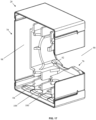
- FIG. 13 is a rear top view of jack housing assembly 26 with front shield wrap 30 in its closed state.
- FIG. 14 is a rear bottom view of jack housing assembly 26 with front shield wrap 30 in its closed state.
- FIG. 15 is a front top exploded view of rear wire cover assembly 28.
- FIG. 16 is a rear bottom exploded view of rear wire cover assembly 28.
- Rear wire cover assembly 28 includes wire cover 76 and wire cover shield wrap 78. Wire cover 76 is placed into wire cover shield wrap 78. Return flanges 80 on wire cover shield wrap 78 catch to flat edges 82 on wire cover 76 to secure the components together.
- FIG. 17 is a front top view of rear wire cover assembly 28.
- Rear wire cover assembly 28 is symmetrically designed to allow cable opening 90 to point to either the left or right after final assembly.
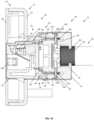
- FIG. 18 is a section view of communications system 10 taken about the center line of conductor 88 4 and conductor 88 7 of an unmated terminated jack assembly 16 secured to shielded patch panel 12.
- Conductors 88 on shielded cable 24 are pressed into slots 86 ( FIG. 7 - FIG. 14 ) of rear sled 36 and terminated to long IDCs 42 of jack housing assembly 26.
- Cut edge 108 on rear sled 36 provides a flat surface for a punch down tool to trim conductors 88 flush.
- Cable opening 90 on rear wire cover assembly 28 allows for rear wire cover assembly 28 to be placed onto jack housing assembly 26 after shielded cable 24 has been terminated to long IDCs 42 of jack housing assembly 26.
- Rear wire cover assembly 28 is then placed over the back end of jack housing assembly 26. If the ends of conductors 88 are cut too long or cut without the use of a punch down tool after termination; rounded surfaces 109 on wire cover 76 of rear wire cover assembly 28 help to push excess conductor or dielectric length into overflow channels 110 on rear sled 36 of jack housing assembly 26.
- Capture slots 100 ( FIG. 15 - FIG. 17 ) on wire cover 76 of rear wire cover assembly 28 pass over round bosses 102 ( FIG. 7 - FIG. 14 ) on rear sled 36 of jack housing assembly 26 and secure rear wire cover assembly 28 to finalize terminated jack assembly 16.
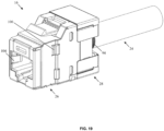
- FIG. 19 is a front top view of terminated jack assembly 16.
- FIG. 20 is a rear top view of terminated jack assembly 16.
- Inner wiping tabs 104 provide a bond between plug shield 23 ( FIG. 1 ) on shielded plug assembly 22 when shielded plug assembly 22 and terminated jack assembly 16 are in a mated state.
- Grounding tabs 106 are designed to bond terminated jack assembly 16 to shielded patch panel 12 when parts are assembled.
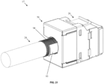
- FIG. 21 is a rear top view of alternate terminated jack assembly 17.
- Terminated jack assembly 17 includes all of the same components as terminated jack assembly 16, with the exception of alternate wire cover shield wrap 79.
- Alternate wire cover shield wrap 79 has identical internal geometry as wire cover shield wrap 78, but instead of inward facing grounding prongs 92, alternate wire cover shield wrap 79 includes grounding flange 93.
- Grounding flange 93 is an outward facing flange designed to bond around braid 94 of shielded cable 24 with the aid of a cable tie (not pictured).
Landscapes
- Details Of Connecting Devices For Male And Female Coupling (AREA)
Abstract
A rear wire cover assembly for a keystone style punchdown jack has a shield wrap and an opening configured to allow the rear wire cover assembly to move in a direction perpendicular to an axis of a cable such as to partially enclose the cable and also such as to allow the rear wire cover assembly to move along the axis of the cable to engage a rear of the keystone style punchdown jack.
Description
- The present invention is related generally to RJ45 style connectors and more specifically to a keystone style punchdown jack with a rear wire cover assembly.
- The market currently offers several Mini-Com shielded TG jack modules and several unshielded keystone style punch down jack modules. What is needed is a shielded keystone jack that utilizes the existing punch down style termination method and is cost competitive to existing shielded Mini-Com jacks with a TG style termination method. Specifically, one with a rear wire cover assembly that can electrically connect a braid of a shielded cable to the shield of the jack and secure conductors to the shield of the jack.
- A rear wire cover assembly for a keystone style punchdown jack has a shield wrap and an opening configured to allow the rear wire cover assembly to move in a direction perpendicular to an axis of a cable such as to partially enclose the cable and also such as to allow the rear wire cover assembly to move along the axis of the cable to engage a rear of the keystone style punchdown jack.
-
-
FIG. 1 is an isometric view ofcommunications system 10. -
FIG. 2 is an isometric exploded view of terminatedjack assembly 16. -
FIG. 3 is a front top exploded view ofjack housing assembly 26. -
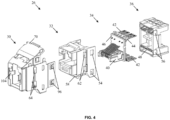
FIG. 4 is a front bottom exploded view ofjack housing assembly 26. -
FIG. 5 is a rear top exploded view ofjack housing assembly 26. -
FIG. 6 depictsfront shield wrap 30 in its open state prior to the final forming. -
FIG. 7 is a front top view ofjack housing assembly 26. -
FIG. 8 is a front bottom view ofjack housing assembly 26. -
FIG. 9 is a rear top view ofjack housing assembly 26 withfront shield wrap 30 in its open state. -
FIG. 10 is a rear bottom view ofjack housing assembly 26 withfront shield wrap 30 in its open state. -
FIG. 11 is a front top view ofjack housing assembly 26 withfront shield wrap 30 in its closed state. -
FIG. 12 is a front bottom view ofjack housing assembly 26 withfront shield wrap 30 in its closed state. -
FIG. 13 is a rear top view ofjack housing assembly 26 withfront shield wrap 30 in its closed state. -
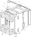
FIG. 14 is a rear bottom view ofjack housing assembly 26 withfront shield wrap 30 in its closed state. -
FIG. 15 is a front top exploded view of rearwire cover assembly 28. -
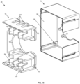
FIG. 16 is a rear bottom exploded view of rearwire cover assembly 28. -
FIG. 17 is a front top view of rearwire cover assembly 28. -
FIG. 18 is a section view ofcommunications system 10 taken about the center line of conductor 884 and conductor 887 of an unmated terminatedjack assembly 16 secured to shieldedpatch panel 12. -
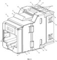
FIG. 19 is a front top view of terminatedjack assembly 16. -
FIG. 20 is a rear top view of terminatedjack assembly 16. -
FIG. 21 is a rear top view of alternate terminatedjack assembly 17. -
FIG. 1 is an isometric view ofcommunications system 10 which includes shieldedpatch panel 12,patch cord assembly 14, and terminatedjack assemblies 16.Communications system 10 can further include cabinets, racks, cable management, patch panels, overhead routing systems, horizontal cabling, and other such equipment. Shieldedpatch panel 12 includes formedmetal panel 18 andfaceplate insert 20.Patch cord assembly 14 includes shieldedplug assembly 22 and shieldedcable 24. -
FIG. 2 is an isometric exploded view of terminatedjack assembly 16. Terminatedjack assembly 16 includes shieldedcable 24,jack housing assembly 26, and rearwire cover assembly 28.Shielded cable 24 includescable jacket 87, conductors 88,conductor divider 89, andbraid 94. -
FIG. 3 is a front top exploded view ofjack housing assembly 26.FIG. 4 is a front bottom exploded view ofjack housing assembly 26.FIG. 5 is a rear top exploded view ofjack housing assembly 26.FIG. 6 is a rear bottom exploded view ofjack housing assembly 26.Jack housing assembly 26 includesfront shield wrap 30,jack housing 32,PCB assembly 34,rear sled 36, and wire map label 38 (FIG. 5 - Fig 6 ).FIG. 3 - FIG. 6 depictfront shield wrap 30 in its open state prior to the final forming.PCB assembly 34 includessled assembly 40,long IDCs 42, IDC Support 44, and PCB 46.PCB assembly 34 is constructed and utilized in a manner identical to current production unshielded keystone punch down jack modules. -
Long IDCs 42 ofPCB assembly 34 are press fit intochannels 48 ofrear sled 36 to keeplong IDCs 42 constrained during the termination process. IDC support 44 ofPCB assembly 34 andlower support wall 50 ofjack housing 32 provide support tolong IDCs 42 ofPCB assembly 34 during the assembly process. Sledassembly 40 ofPCB assembly 34 slides into opening 52 on jack housing 32 (FIG. 5 - FIG. 6 ). D-window latches 54 onjack housing 32 snap overcatches 56 ofrear sled 36 to secure components together.Wire map label 38 has an adhesive backing that secures it torear sled 36.Jack housing 32,PCB assembly 34,rear sled 36, andwire map label 38, in an assembled state, are slid intofront shield wrap 30.Flexible latch 58 onjack housing 32 slides through opening 60 offront shield wrap 30. Side stops 62 ofjack housing 32 pass throughwindows 64 offront shield wrap 30 and help keep all components from separating prior to the final forming offront shield wrap 30. -
FIG. 7 is a front top view ofjack housing assembly 26 withfront shield wrap 30 in its open state prior to the final assembly.FIG. 8 is a front bottom view ofjack housing assembly 26 withfront shield wrap 30 in its open state.FIG. 9 is a rear top view ofjack housing assembly 26 withfront shield wrap 30 in its open state.FIG. 10 is a rear bottom view ofjack housing assembly 26 withfront shield wrap 30 in its open state.Rear tabs 66 pass throughholes 68 asflange 70 is brought to a final position forfront shield wrap 30.Rear tabs 66 are then formed overedges 69 ofholes 68 to securefront shield wrap 30 in a locked position.Front tabs 72 are formed overoffset geometry 74 onflange 70 offront shield wrap 30 for added security and shielding continuity. -
FIG. 11 is a front top view ofjack housing assembly 26 withfront shield wrap 30 in its closed state.FIG. 12 is a front bottom view ofjack housing assembly 26 withfront shield wrap 30 in its closed state.FIG. 13 is a rear top view ofjack housing assembly 26 withfront shield wrap 30 in its closed state.FIG. 14 is a rear bottom view ofjack housing assembly 26 withfront shield wrap 30 in its closed state. -
FIG. 15 is a front top exploded view of rearwire cover assembly 28.FIG. 16 is a rear bottom exploded view of rearwire cover assembly 28. Rearwire cover assembly 28 includeswire cover 76 and wirecover shield wrap 78.Wire cover 76 is placed into wirecover shield wrap 78.Return flanges 80 on wirecover shield wrap 78 catch toflat edges 82 onwire cover 76 to secure the components together. -
FIG. 17 is a front top view of rearwire cover assembly 28. Rearwire cover assembly 28 is symmetrically designed to allowcable opening 90 to point to either the left or right after final assembly. -
FIG. 18 is a section view ofcommunications system 10 taken about the center line of conductor 884 and conductor 887 of an unmated terminatedjack assembly 16 secured to shieldedpatch panel 12. Conductors 88 on shieldedcable 24 are pressed into slots 86 (FIG. 7 - FIG. 14 ) ofrear sled 36 and terminated tolong IDCs 42 ofjack housing assembly 26. Cutedge 108 onrear sled 36 provides a flat surface for a punch down tool to trim conductors 88 flush. Cable opening 90 on rearwire cover assembly 28 allows for rearwire cover assembly 28 to be placed ontojack housing assembly 26 after shieldedcable 24 has been terminated tolong IDCs 42 ofjack housing assembly 26. Rearwire cover assembly 28 is then placed over the back end ofjack housing assembly 26. If the ends of conductors 88 are cut too long or cut without the use of a punch down tool after termination; roundedsurfaces 109 onwire cover 76 of rearwire cover assembly 28 help to push excess conductor or dielectric length intooverflow channels 110 onrear sled 36 ofjack housing assembly 26. - Grounding prongs 92 on wire cover shield wrap 78 of rear
wire cover assembly 28 bond to braid 94 of shieldedcable 24. Wiping tabs 96 (FIG. 3 - FIG. 14 ) on front shield wrap 30 ofjack housing assembly 26 make connection to inside walls 98 (FIG. 15 - FIG. 17 ) on wire cover shield wrap 78 of rearwire cover assembly 28 to create a fully bonded assembly. Capture slots 100 (FIG. 15 - FIG. 17 ) onwire cover 76 of rearwire cover assembly 28 pass over round bosses 102 (FIG. 7 -FIG. 14 ) onrear sled 36 ofjack housing assembly 26 and secure rearwire cover assembly 28 to finalize terminatedjack assembly 16.Divider walls 84 onwire cover 76 of rearwire cover assembly 28 slide intoslots 86 ofrear sled 36 ofjack housing assembly 26 and help to secure conductors 88 on shieldedcable 24. -
FIG. 19 is a front top view of terminatedjack assembly 16.FIG. 20 is a rear top view of terminatedjack assembly 16.Inner wiping tabs 104 provide a bond between plug shield 23 (FIG. 1 ) on shieldedplug assembly 22 when shieldedplug assembly 22 and terminatedjack assembly 16 are in a mated state. Groundingtabs 106 are designed to bond terminatedjack assembly 16 to shieldedpatch panel 12 when parts are assembled. -
FIG. 21 is a rear top view of alternate terminatedjack assembly 17.Terminated jack assembly 17 includes all of the same components as terminatedjack assembly 16, with the exception of alternate wirecover shield wrap 79. Alternate wirecover shield wrap 79 has identical internal geometry as wirecover shield wrap 78, but instead of inward facing grounding prongs 92, alternate wirecover shield wrap 79 includes groundingflange 93. Groundingflange 93 is an outward facing flange designed to bond around braid 94 of shieldedcable 24 with the aid of a cable tie (not pictured).
Claims (8)
- A rear wire cover assembly for a keystone style punchdown jack comprising an opening configured to allow the rear wire cover assembly to move in a direction perpendicular to an axis of a cable such as to partially enclose the cable and also such as to allow the rear wire cover assembly to move along the axis of the cable to engage a rear of the keystone style punchdown jack and a shield wrap.
- The rear wire cover assembly of claim 1, wherein the rear wire cover assembly is symmetrical in order to allow it to partially enclose a cable from opposite directions.
- The rear wire cover assembly of any preceding claim, further comprising divider walls configured to slide into slots on the rear of the keystone style puchdown jack such as to secure conductors terminated to the keystone style puchdown jack.
- The rear wire cover assembly of any preceding claim, wherein inside walls of the wire cover shield wrap are configured to engage wiping taps on a shield of the keystone style punchdown jack.
- The rear wire cover assembly of any preceding claim, wherein the rear wire cover shield wrap comprises grounding prongs configured to engage a braid of a shielded cable.
- The rear wire cover assembly of any preceding claim, wherein the rear wire cover shield wrap comprises a grounding flange to engage a braid of a shielded cable.
- A jack comprising the rear wire cover assembly of any preceding claim.
- The jack of claim 7 comprising a keystone style punchdown jack.
Applications Claiming Priority (1)
| Application Number | Priority Date | Filing Date | Title |
|---|---|---|---|
| US18/098,183 US20240243526A1 (en) | 2023-01-18 | 2023-01-18 | Shielded keystone style punchdown jack |
Publications (1)
| Publication Number | Publication Date |
|---|---|
| EP4404394A1 true EP4404394A1 (en) | 2024-07-24 |
Family
ID=89575047
Family Applications (1)
| Application Number | Title | Priority Date | Filing Date |
|---|---|---|---|
| EP24151451.2A Pending EP4404394A1 (en) | 2023-01-18 | 2024-01-11 | Shielded keystone style punchdown jack |
Country Status (3)
| Country | Link |
|---|---|
| US (1) | US20240243526A1 (en) |
| EP (1) | EP4404394A1 (en) |
| CN (1) | CN222966447U (en) |
Citations (4)
| Publication number | Priority date | Publication date | Assignee | Title |
|---|---|---|---|---|
| US20070026736A1 (en) * | 2005-06-14 | 2007-02-01 | Leviton Manufacturing Co., Inc. | Connector isolation shielding system and method |
| US20090098777A1 (en) * | 2007-10-04 | 2009-04-16 | Hubbell Incorporated. | Alien crosstalk preventive cover |
| US20120202389A1 (en) * | 2011-02-04 | 2012-08-09 | Jason Erickson | Spring assembly with spring members biasing and capacitively coupling jack contacts |
| US10777953B2 (en) * | 2016-08-15 | 2020-09-15 | Commscope Technologies Llc | Connector assembly with grounding |
Family Cites Families (11)
| Publication number | Priority date | Publication date | Assignee | Title |
|---|---|---|---|---|
| US6238231B1 (en) * | 1997-09-03 | 2001-05-29 | Avaya Technology Corp. | Strain relief apparatus for use in a communication plug |
| FR2768862B1 (en) * | 1997-09-22 | 1999-12-24 | Infra Sa | LOW POWER SOCKET WITH ORGANIZER REAR CAP |
| DE10051097C2 (en) * | 2000-08-17 | 2002-11-28 | Krone Gmbh | Electrical connector |
| US6767241B1 (en) * | 2003-05-28 | 2004-07-27 | Avaya Technology Corp. | Back-end variation control cap for use with a jack module |
| US7118405B2 (en) * | 2004-12-30 | 2006-10-10 | John Peng | Structure and method for connecting conducting lines to terminals |
| GB0622461D0 (en) * | 2006-11-13 | 2006-12-20 | Tyco Electronics Amp Es Sa | A connector |
| FR2911435B1 (en) * | 2007-01-12 | 2009-04-17 | Legrand France | SIMPLIFIED MOUNTING RECORDING RECEPTACLE FOR MULTICONDUCTOR CABLE |
| TWM320772U (en) * | 2007-03-21 | 2007-10-11 | Surtec Ind Inc | Signal communication socket with pierce terminal |
| US7563125B2 (en) * | 2007-11-12 | 2009-07-21 | Tyco Electronics Corporation | Jack assembly for reducing crosstalk |
| US7972150B1 (en) * | 2010-11-04 | 2011-07-05 | Jyh Eng Technology Co., Ltd. | Alien crosstalk preventive electrical socket, electrical plug and network cable |
| US9130283B1 (en) * | 2014-02-18 | 2015-09-08 | Jyh Eng Technology Co., Ltd. | Electrical connector with multi-direction cable installation capability |
-
2023
- 2023-01-18 US US18/098,183 patent/US20240243526A1/en active Pending
-
2024
- 2024-01-11 EP EP24151451.2A patent/EP4404394A1/en active Pending
- 2024-01-15 CN CN202420101745.6U patent/CN222966447U/en active Active
Patent Citations (4)
| Publication number | Priority date | Publication date | Assignee | Title |
|---|---|---|---|---|
| US20070026736A1 (en) * | 2005-06-14 | 2007-02-01 | Leviton Manufacturing Co., Inc. | Connector isolation shielding system and method |
| US20090098777A1 (en) * | 2007-10-04 | 2009-04-16 | Hubbell Incorporated. | Alien crosstalk preventive cover |
| US20120202389A1 (en) * | 2011-02-04 | 2012-08-09 | Jason Erickson | Spring assembly with spring members biasing and capacitively coupling jack contacts |
| US10777953B2 (en) * | 2016-08-15 | 2020-09-15 | Commscope Technologies Llc | Connector assembly with grounding |
Also Published As
| Publication number | Publication date |
|---|---|
| US20240243526A1 (en) | 2024-07-18 |
| CN222966447U (en) | 2025-06-10 |
Similar Documents
| Publication | Publication Date | Title |
|---|---|---|
| CN216529380U (en) | Communication connector | |
| US5562493A (en) | Network interface assembly and mounting frame | |
| US7335066B2 (en) | Network connector and connection system | |
| US7083472B2 (en) | Shielded jack assemblies and methods for forming a cable termination | |
| US4859201A (en) | Data communications outlet | |
| WO2021101974A1 (en) | Field terminable single pair ethernet connector with angled contacts | |
| US8650750B2 (en) | Process for assembling a data cable connector module | |
| US11387606B2 (en) | Communication connectors utilizing multiple contact points | |
| US11056840B2 (en) | Electrical connector system with alien crosstalk reduction devices | |
| EP2003741A1 (en) | A shielded sub-miniature connection assembly and process for equipping such a connection assembly | |
| US20240396256A1 (en) | Single-pair ethernet mount housing | |
| JPH01501825A (en) | electrical connectors | |
| US20240243526A1 (en) | Shielded keystone style punchdown jack | |
| US20240243524A1 (en) | Shielded keystone style punchdown jack | |
| US20250233349A1 (en) | Shielded jack flange termination | |
| EP4485710A1 (en) | Shielded keystone punchdown jack | |
| US12322914B2 (en) | Field terminable single pair ethernet connector with angled contacts | |
| EP0197994B1 (en) | Shielded electrical connector | |
| WO2024049650A1 (en) | Field terminable single pair ethernet connector with angled contacts |
Legal Events
| Date | Code | Title | Description |
|---|---|---|---|
| PUAI | Public reference made under article 153(3) epc to a published international application that has entered the european phase |
Free format text: ORIGINAL CODE: 0009012 |
|
| STAA | Information on the status of an ep patent application or granted ep patent |
Free format text: STATUS: THE APPLICATION HAS BEEN PUBLISHED |
|
| AK | Designated contracting states |
Kind code of ref document: A1 Designated state(s): AL AT BE BG CH CY CZ DE DK EE ES FI FR GB GR HR HU IE IS IT LI LT LU LV MC ME MK MT NL NO PL PT RO RS SE SI SK SM TR |
|
| STAA | Information on the status of an ep patent application or granted ep patent |
Free format text: STATUS: REQUEST FOR EXAMINATION WAS MADE |
|
| 17P | Request for examination filed |
Effective date: 20250123 |