EP4404364A1 - Pressure-regulating valve for power storage module - Google Patents
Pressure-regulating valve for power storage module Download PDFInfo
- Publication number
- EP4404364A1 EP4404364A1 EP22869719.9A EP22869719A EP4404364A1 EP 4404364 A1 EP4404364 A1 EP 4404364A1 EP 22869719 A EP22869719 A EP 22869719A EP 4404364 A1 EP4404364 A1 EP 4404364A1
- Authority
- EP
- European Patent Office
- Prior art keywords
- pressure
- power storage
- storage module
- regulating valve
- valve body
- Prior art date
- Legal status (The legal status is an assumption and is not a legal conclusion. Google has not performed a legal analysis and makes no representation as to the accuracy of the status listed.)
- Pending
Links
Images




Classifications
-
- H—ELECTRICITY
- H01—ELECTRIC ELEMENTS
- H01M—PROCESSES OR MEANS, e.g. BATTERIES, FOR THE DIRECT CONVERSION OF CHEMICAL ENERGY INTO ELECTRICAL ENERGY
- H01M50/00—Constructional details or processes of manufacture of the non-active parts of electrochemical cells other than fuel cells, e.g. hybrid cells
- H01M50/30—Arrangements for facilitating escape of gases
- H01M50/317—Re-sealable arrangements
- H01M50/325—Re-sealable arrangements comprising deformable valve members, e.g. elastic or flexible valve members
-
- F—MECHANICAL ENGINEERING; LIGHTING; HEATING; WEAPONS; BLASTING
- F16—ENGINEERING ELEMENTS AND UNITS; GENERAL MEASURES FOR PRODUCING AND MAINTAINING EFFECTIVE FUNCTIONING OF MACHINES OR INSTALLATIONS; THERMAL INSULATION IN GENERAL
- F16K—VALVES; TAPS; COCKS; ACTUATING-FLOATS; DEVICES FOR VENTING OR AERATING
- F16K15/00—Check valves
- F16K15/14—Check valves with flexible valve members
-
- H—ELECTRICITY
- H01—ELECTRIC ELEMENTS
- H01M—PROCESSES OR MEANS, e.g. BATTERIES, FOR THE DIRECT CONVERSION OF CHEMICAL ENERGY INTO ELECTRICAL ENERGY
- H01M50/00—Constructional details or processes of manufacture of the non-active parts of electrochemical cells other than fuel cells, e.g. hybrid cells
- H01M50/30—Arrangements for facilitating escape of gases
- H01M50/317—Re-sealable arrangements
-
- H—ELECTRICITY
- H01—ELECTRIC ELEMENTS
- H01M—PROCESSES OR MEANS, e.g. BATTERIES, FOR THE DIRECT CONVERSION OF CHEMICAL ENERGY INTO ELECTRICAL ENERGY
- H01M50/00—Constructional details or processes of manufacture of the non-active parts of electrochemical cells other than fuel cells, e.g. hybrid cells
- H01M50/30—Arrangements for facilitating escape of gases
- H01M50/392—Arrangements for facilitating escape of gases with means for neutralising or absorbing electrolyte; with means for preventing leakage of electrolyte through vent holes
-
- H—ELECTRICITY
- H01—ELECTRIC ELEMENTS
- H01M—PROCESSES OR MEANS, e.g. BATTERIES, FOR THE DIRECT CONVERSION OF CHEMICAL ENERGY INTO ELECTRICAL ENERGY
- H01M50/00—Constructional details or processes of manufacture of the non-active parts of electrochemical cells other than fuel cells, e.g. hybrid cells
- H01M50/60—Arrangements or processes for filling or topping-up with liquids; Arrangements or processes for draining liquids from casings
- H01M50/673—Containers for storing liquids; Delivery conduits therefor
-
- H—ELECTRICITY
- H01—ELECTRIC ELEMENTS
- H01M—PROCESSES OR MEANS, e.g. BATTERIES, FOR THE DIRECT CONVERSION OF CHEMICAL ENERGY INTO ELECTRICAL ENERGY
- H01M50/00—Constructional details or processes of manufacture of the non-active parts of electrochemical cells other than fuel cells, e.g. hybrid cells
- H01M50/60—Arrangements or processes for filling or topping-up with liquids; Arrangements or processes for draining liquids from casings
- H01M50/673—Containers for storing liquids; Delivery conduits therefor
- H01M50/682—Containers for storing liquids; Delivery conduits therefor accommodated in battery or cell casings
-
- Y—GENERAL TAGGING OF NEW TECHNOLOGICAL DEVELOPMENTS; GENERAL TAGGING OF CROSS-SECTIONAL TECHNOLOGIES SPANNING OVER SEVERAL SECTIONS OF THE IPC; TECHNICAL SUBJECTS COVERED BY FORMER USPC CROSS-REFERENCE ART COLLECTIONS [XRACs] AND DIGESTS
- Y02—TECHNOLOGIES OR APPLICATIONS FOR MITIGATION OR ADAPTATION AGAINST CLIMATE CHANGE
- Y02E—REDUCTION OF GREENHOUSE GAS [GHG] EMISSIONS, RELATED TO ENERGY GENERATION, TRANSMISSION OR DISTRIBUTION
- Y02E60/00—Enabling technologies; Technologies with a potential or indirect contribution to GHG emissions mitigation
- Y02E60/10—Energy storage using batteries
Definitions
- the present invention relates to a pressure-regulating valve for a power storage module.
- a power storage module including a pressure-regulating valve that opens to discharge gas from the module when the gas such as hydrogen gas is generated due to overdischarge or the like and the inside of the module has a predetermined pressure.
- pressure-regulating valve for a power storage module there is known a pressure-regulating valve capable of pressure regulation of a plurality of internal spaces between bipolar electrodes with a simple configuration (see Patent Literature 1, for example).
- Patent Literature 1 International Publication No. WO 2019/064843
- an electrolyte may be discharged with gas when the valve opens.
- the electrolyte may be accumulated inside the pressure-regulating valve for a power storage module.
- the conventional pressure-regulating valve for a power storage module since in the conventional pressure-regulating valve for a power storage module, a plurality of valve bodies are provided in one discharge port, it has been difficult to discharge an electrolyte without delay. In addition, since it is difficult for the conventional pressure-regulating valve for a power storage module to discharge an electrolyte without delay, a plurality of valve bodies are in the state of being immersed in the electrolyte. In this case, the conventional pressure-regulating valve for a power storage module has a possibility of causing a short circuit between a plurality of cells through the electrolyte when the plurality of valve bodies simultaneously open and the electrolyte is discharged.
- the present invention is made in view of the aforementioned problem, and it is an object of the present invention to provide a pressure-regulating valve for a power storage module capable of improving discharge of an electrolyte.
- a pressure-regulating valve for a power storage module includes a valve body portion that opens in response to pressure in a power storage module to release the pressure in the power storage module, and an electrolyte reservoir portion provided between the valve body portion and the power storage module, and capable of storing an electrolyte leaking from an inside of the power storage module toward the valve body portion.
- the electrolyte reservoir portion is configured by a member separate from the valve body portion.
- the electrolyte reservoir portion is formed into a plate shape.
- the electrolyte reservoir portion has an air chamber having a space communicating with the valve body portion.
- the air chamber is provided on each of one end side and another end side of the electrolyte reservoir portion, and the electrolyte reservoir portion has a flow path portion that causes the air chamber provided on the one end side and the air chamber provided on the other end side to communicate with each other.
- the electrolyte reservoir portion has a plurality of the air chambers.
- Fig. 1 is a perspective view schematically showing a power storage module 500 to which a pressure-regulating valve 1 for a power storage module according to the embodiment of the present invention is connected.
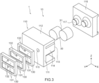
- Fig. 2 and Fig. 3 are exploded perspective views for showing a rough configuration of the pressure-regulating valve 1 for a power storage module according to the embodiment of the present invention.
- Fig. 4 is a sectional view of the pressure-regulating valve 1 for a power storage module.
- the pressure-regulating valve 1 for a power storage module is shown by a partially enlarged view in which a part A shown in Fig. 1 is enlarged.
- an axial direction of a circular columnar valve body 30 is defined as a Y-axis direction.
- the Y-axis direction is also referred to as a front-back direction.
- a +Y-axis direction is also referred to as one end side
- a -Y-axis direction is also referred to as another end side.
- a direction in which the pressure-regulating valve 1 for a power storage module is seen toward the +Y-axis direction is defined as a front direction.
- the width direction is a longitudinal direction of a valve body portion 10 of the pressure-regulating valve 1 for a power storage module.
- the width direction is also referred to as a left-right direction.
- a direction (Z-axis direction) orthogonal to both the front-back direction (Y-axis direction) and the left-right direction (X-axis direction) is also referred to as an up-down direction or a height direction.
- the pressure-regulating valve 1 for a power storage module includes the valve body portion 10 that opens in response to pressure in the power storage module 500 to release the pressure in the power storage module 500, and an electrolyte reservoir portion 130 provided between the valve body portion 10 and the power storage module 500 and capable of storing an electrolyte leaking from an inside of the power storage module 500 to a valve body portion 10 side.
- the pressure-regulating valve 1 closes an opening 503 that communicates with spaces among the plurality of electrode plates provided in the frame body 502.
- the valve body portion 10 has one end connected to the opening 503, and has an internal space S1 inside.
- the columnar valve body 30 which is an elastic member is accommodated.
- the valve body portion 10 includes a bottom portion 111 provided on one end side, an opening portion 113 provided on another end side, a case cylindrical portion 114 provided in the internal space S1 of the valve body portion 10 and capable of accommodating the valve body 30, a pressure introducing portion 115 penetrating through the bottom portion 111, a cover portion 116 as a lid portion that closes the opening portion 113, and a protrusion portion 117 that is provided at the cover portion 116 and contacts an end surface 31 of the valve body 30 from the other end side.
- the electrolyte reservoir portion 130 includes an air chamber 131 that is a space communicating with an outside of the valve body portion 10, specifically, the opening 503 of the frame body 502 and the pressure introducing portion 115.
- the pressure-regulating valve 1 for a power storage module will be specifically described.
- the pressure-regulating valve 1 for a power storage module (hereinafter referred to as the "pressure-regulating valve 1") includes the valve body portion 10 that accommodates the valve body 30 and is attached to the opening 503 of the power storage module 500.
- valve body portion 10 is not particularly limited, a synthetic resin or the like can be cited, for example.
- the valve body portion 10 can be formed into a substantially rectangular parallelepiped shape or the like, for example.
- a shape of the valve body portion 10 is not particularly limited if the valve body portion 10 can close the opening 503.
- a size of the valve body portion 10 can also be appropriately set in relation to a size of the power storage module 500 or the opening 503 and is not particularly limited.
- the valve body portion 10 is configured by a case portion 110 and the cover portion 116 as a separate member.
- the electrolyte reservoir portion 130 is configured as a separate member from the valve body portion 10.
- materials of the case portion 110, the cover portion 116, and the electrolyte reservoir portion 130 may be the same material, or different materials.
- Fig. 5 is a front view of the case portion 110 of the pressure-regulating valve 1 for a power storage module.
- Fig. 6 is a sectional view taken along line A-A of the case portion 110.
- the case portion 110 is a box-shaped member formed into a rectangular parallelepiped shape in which a dimension in the width direction is longer than dimensions in the height direction and the front-back direction, for example.
- the case portion 110 includes the bottom portion 111, an outer peripheral wall part 112, the opening portion 113, the case cylindrical portion 114, and the pressure introducing portion 115.
- the bottom portion 111 is provided on the one end side of the case portion 110.
- the bottom portion 111 is attached to face the opening 503 via the electrolyte reservoir portion 130 in the state in which the pressure-regulating valve 1 is attached to the opening 503 of the frame body 502 as shown in Fig. 4 .
- the bottom portion 111 is formed to be able to close the opening 503 via the electrolyte reservoir portion 130 in the state of being attached to the opening 503.
- the outer peripheral wall part 112 is provided at an end portion of an outer periphery of the bottom portion 111.
- the outer peripheral wall part 112 is provided at an end portion 1111 in the up-down direction of the bottom portion 111.
- the outer peripheral wall part 112 is a wall-shaped member that rises from the end portion 1111 in the up-down direction of the bottom portion 111 to the other end side (-Y-axis direction).
- the bottom portion 111 and the outer peripheral wall part 112 form the internal space S1 that is isolated from an outside inside the case portion 110.
- the opening portion 113 is provided in an end portion 1122 on another end side of the outer peripheral wall part 112. As a result of the opening portion 113 being provided, another end side of the internal space S1 of the case portion 110 is opened to the outside.
- the case cylindrical portion 114 is provided in the internal space S1 of the case portion 110.
- the case cylindrical portion 114 is a cylindrical or substantially cylindrical part having an axial direction in the front-back direction (Y-axis direction) in the case portion 110.
- one or a plurality of case cylindrical portions 114 are provided in the internal space S1.
- the number of case cylindrical portions 114 is not particularly limited.
- the case cylindrical portion 114 has one end integrated with an inner surface 1112 that is a surface on another end side of the bottom portion 111.
- the case cylindrical portion 114 has another end opened to the opening portion 113.
- the case cylindrical portion 114 can accommodate the valve body 30 in a cylindrical or substantially cylindrical accommodation space S2 inside.
- the pressure-regulating valve 1 can accommodate a plurality of valve bodies 30 correspondingly to the number of case cylindrical portions 114 provided in the internal space S1.
- the pressure introducing portion 115 is provided in a cylindrical portion bottom portion 1113 that is a bottom portion located inside the case cylindrical portion 114.
- the pressure introducing portion 115 is a through-hole extending in the Y-axis direction in the cylindrical portion bottom portion 1113. In other words, the pressure introducing portion 115 penetrates through one end side and another end side of the cylindrical portion bottom portion 1113.
- the pressure introducing portion 115 is not limited to the one provided in a vicinity of a center of a circular shape or substantially circular shape of the cylindrical portion bottom portion 1113 as shown in Fig. 4 . Further, the pressure introducing portion 115 is typically a circular columnar space, but the shape of the pressure introducing portion 115 is not particularly limited, and can be, for example, an elliptical columnar or a polygonal prism-shaped space.
- Fig. 7 is a front view of the cover portion 116 of the pressure-regulating valve 1 for a power storage module.
- Fig. 8 is a plan view of the cover portion 116.
- the cover portion body 1161 defines an approximate shape of the aforementioned plate-like or substantially plate-like cover portion 116.
- the shape of the cover portion body 1161 is not limited to the shape shown in Fig. 7 and Fig. 8 if only the cover portion 116 can be combined with the case portion 110.
- the protrusion portion 117 is a part having a protruded shape protruding in the Y-axis direction from the cover portion body 1161.
- the protrusion portions 117 are provided correspondingly to the number of case cylindrical portions 114.
- the protrusion portion 117 is provided at a position inside a cylindrical surface of the case cylindrical portion 114 in the state in which the cover portion 116 and the case portion 110 are combined as shown in Fig. 3 .
- the protrusion portion 117 protrudes to a case portion 110 side located on the one end side (+Y-axis direction), and presses the valve body 30 positioned inside the case cylindrical portion 114 from an opening portion 113 side in the state in which the cover portion 116 and the case portion 110 are combined.
- the protrusion portion 117 contacts the end surface 31 of the valve body 30. By closing the opening portion 113 of the case portion 110 with the cover portion 116, the protrusion portion 117 pressurizes the valve body 30. The valve body 30 closes the pressure introducing portion 115 airtightly as described later.
- a shape and a dimension of the protrusion portion 117 are not particularly limited, and the protrusion portion 117 can have, for example, a circular columnar shape, an elliptical columnar shape, a polygonal prism shape, or the like.
- the electrolyte reservoir portion 130 is attached to one end side of the bottom portion 111 of the case portion 110 in the valve body portion 10.
- a plurality of, for example, three electrolyte reservoir portions 130 may be attached, or the single electrolyte reservoir portion 130 may be attached.
- Fig. 9 is a perspective view showing the electrolyte reservoir portion 130 of the pressure-regulating valve 1.
- Fig. 10 is a front view of the electrolyte reservoir portion 130.
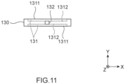
- Fig. 11 is a plan view of the electrolyte reservoir portion 130.
- the electrolyte reservoir portion 130 has the air chamber 131 and a flow path portion 132.
- the electrolyte reservoir portion 130 is formed as a separate member from the case portion 110 and the cover portion 116.
- the electrolyte reservoir portion 130 is formed in a plate shape or a substantially plate shape in which a dimension in the front-back direction (Y-axis direction) is short with respect to dimensions in the height direction (Z-axis direction) and the width direction (X-axis direction) of the pressure-regulating valve 1.
- the air chamber 131 is formed into a recessed shape having a depth in the Y-axis direction as shown in Fig. 11 in surfaces on one end side (+Y-axis direction) and another end side (-Y-axis direction) of the electrolyte reservoir portion 130.
- an air chamber opening portion 1311 opens on the surfaces on the one end side (+Y-axis direction) and the other end side (-Y-axis direction) of the electrolyte reservoir portion 130.
- a shape of the air chamber 131 is, for example, a rectangle or substantially rectangle in plan view as shown in Fig. 10 . Note that the shape of the air chamber 131 is not limited to the aforementioned shape if the air chamber 131 can store the electrolyte, compressed gas or the like discharged from the opening 503 of the power storage module 500.
- the air chambers 131 are provided at a total of four spots, for example, two spots on each of the surfaces on the one end side (+Y-axis direction) and on the other end side (-Y-axis direction). Note that the number of air chambers 131 is not limited to the aforementioned example.
- the flow path portion 132 is a hole that penetrates through respective bottom portions 1312 in the air chamber 131 on the one end side and the air chamber 131 on the other end side, in the electrolyte reservoir portion 130.
- the flow path portion 132 causes the air chambers 131 provided on both the one end side and the other end side of the electrolyte reservoir portion 130 to communicate with each other.
- a plurality of (for example, three) electrolyte reservoir portions 130 are attached by being stacked on each other in the front-back direction (Y-axis direction) that is a discharge direction of emissions such as the electrolyte or compressed gas discharged from the opening 503 of the power storage module 500.
- the air chamber opening portion 1311 on the one end side faces the opening 503 of the frame body 502.
- the electrolyte reservoir portion 130 is positioned in this manner, the air chamber 131 on the one end side communicates with the opening 503 of the frame body 502.
- the air chamber opening portion 1311 on the other end side faces the opening 1151 on the one end side of the pressure introducing portion 115 of the case portion 110.
- the air chamber 131 on the other end side communicates with the pressure introducing portion 115.
- a flow path in which the air chambers 131 and the flow path portions 132 communicate with each other to penetrate in the front-back direction is formed. Note that the number of electrolyte reservoir portions 130 is not limited to the aforementioned number.
- the pressure-regulating valve 1 can cope with even the case in which the overflowing electrolyte increases.
- the valve body 30 is a columnar valve body to be accommodated in the case cylindrical portion 114 of the case portion 110 in the valve body portion 10.
- a material of the valve body 30 is, for example, an elastic member such as a rubber.
- the material of the valve body 30 is not particularly limited as long as the material is an elastic member.
- the valve body 30 is positioned to cover a cylindrical portion bottom portion 1113 side in the case cylindrical portion 114. In the valve body 30, a length in the axial direction (Y-axis direction) of the valve body 30 is shorter as compared with an outside diameter.
- the valve body 30 has a columnar shape, in which the length in the axial direction is shorter as compared with the outside diameter as described above, and the "columnar shape" can also be referred to as a plate shape, or board shape. More specifically the valve body 30 can be described as substantially disk-shaped or the like.
- the valve body 30 closes an opening of the pressure introducing portion 115 by being inserted into the case cylindrical portion 114.
- an air-tight state is maintained until the inside of the power storage module 500 reaches a desired pressure, in the state in which the pressure-regulating valve 1 is attached to the power storage module 500.
- internal pressure the pressure inside the power storage module 500
- the valve body 30 separates from the cylindrical portion bottom portion 1113 and opens in response to the internal pressure of the power storage module 500.
- a value of the internal pressure of the power storage module 500 at which the valve body 30 separates from the cylindrical portion bottom portion 1113 is determined to be able to avoid the internal pressure of the power storage module 500 becoming excessively large by the valve body 30 opening.
- the value of the pressure of the inside of the power storage module 500 at which the valve body 30 separates from the cylindrical portion bottom portion 1113 can change depending on various conditions.
- the value of the above-described internal pressure is a value capable of changing according to individual difference (variation) and a secular change of the valve body 30.
- the compressed gas in the power storage module 500 is introduced into the pressure-regulating valve 1 from the power storage module 500.
- the pressure inside the power storage module 500 is reduced.
- the valve body 30 returns to an original position inside the case cylindrical portion 114, that is, a position in contact with the cylindrical portion bottom portion 1113, by an elastic force, and closes the pressure introducing portion 115 airtightly.
- the electrolyte may be discharged with the compressed gas when the compressed gas in the power storage module 500 is discharged from the gap generated between the valve body 30 and the cylindrical portion bottom portion 1113 as a result of the valve body 30 separating from the cylindrical portion bottom portion 1113.
- the electrolyte may accumulate inside the case cylindrical portion 114.
- the pressure-regulating valve 1 is provided with the electrolyte reservoir portion 130 having the air chambers 131 on a front side (one end side) of the pressure introducing portion 115 in the flow path from the opening 503 of the power storage module 500 to the case portion 110.
- the air chamber 131 is the space having a predetermined capacity capable of storing emissions such as the electrolyte discharged from the opening 503 of the power storage module 500 as shown in Fig. 4 . Therefore, according to the pressure-regulating valve 1, by having the air chambers 131, it is possible to suppress discharge of emissions such as the electrolyte, in particular, ejection of the emissions due to a sudden change in pressure.
- the pressure-regulating valve 1 can prevent a short circuit from occurring between a plurality of cells through the electrolyte when the plurality of valve bodies 30 simultaneously open and the electrolyte is discharged.
- the present invention is not limited to the embodiment of the present invention described above, but includes all aspects included in the idea and the claims of the present invention. Further, the respective components may be selectively combined as appropriate to exhibit at least part of the aforementioned problem and effects. For example, the shape, material, disposition, size and the like of each of the components in the above-described embodiment can be appropriately changed according to a specific use aspect of the present invention.
- the case portion 110, the cover portion 116, and the electrolyte reservoir portion 130 are respectively separate bodies (separate members), but they are not limited to the form like this.
- the case portion 110 and the electrolyte reservoir portion 130 may be integrated.
- the air chamber 131 may be provided in the case portion 110.
- the air chamber 131 can communicate in the front-back direction (Y-axis direction) in the electrolyte reservoir portion 130, and is not limited to those provided respectively on the one end side and the other end side of the electrolyte reservoir portion 130. In other words, in the electrolyte reservoir portion 130, the air chamber 131 itself may communicate in the front-back direction (Y-axis direction) without having the flow path portion 132.
- the air chamber 131 may be provided, for example, on either one of the one end side or the other end side of the electrolyte reservoir portion 130, and may communicate with another one of the one end side or the other end side of the electrolyte reservoir portion 130 by the flow path portion 132.
Landscapes
- Chemical & Material Sciences (AREA)
- Chemical Kinetics & Catalysis (AREA)
- Electrochemistry (AREA)
- General Chemical & Material Sciences (AREA)
- Engineering & Computer Science (AREA)
- General Engineering & Computer Science (AREA)
- Mechanical Engineering (AREA)
- Gas Exhaust Devices For Batteries (AREA)
Abstract
Description
- The present invention relates to a pressure-regulating valve for a power storage module.
- Conventionally, in power storage modules such as a nickel hydrogen battery, there has been known a power storage module including a pressure-regulating valve that opens to discharge gas from the module when the gas such as hydrogen gas is generated due to overdischarge or the like and the inside of the module has a predetermined pressure. Note that in the pressure-regulating valves for a power storage module (hereinafter referred to as "pressure-regulating valve for a power storage module"), there is known a pressure-regulating valve capable of pressure regulation of a plurality of internal spaces between bipolar electrodes with a simple configuration (see
Patent Literature 1, for example). - Patent Literature 1: International Publication No.
WO 2019/064843 - Incidentally, in a pressure-regulating valve for a power storage module, an electrolyte may be discharged with gas when the valve opens. In this case, the electrolyte may be accumulated inside the pressure-regulating valve for a power storage module.
- However, since in the conventional pressure-regulating valve for a power storage module, a plurality of valve bodies are provided in one discharge port, it has been difficult to discharge an electrolyte without delay. In addition, since it is difficult for the conventional pressure-regulating valve for a power storage module to discharge an electrolyte without delay, a plurality of valve bodies are in the state of being immersed in the electrolyte. In this case, the conventional pressure-regulating valve for a power storage module has a possibility of causing a short circuit between a plurality of cells through the electrolyte when the plurality of valve bodies simultaneously open and the electrolyte is discharged.
- The present invention is made in view of the aforementioned problem, and it is an object of the present invention to provide a pressure-regulating valve for a power storage module capable of improving discharge of an electrolyte.
- In order to attain the above-described object, a pressure-regulating valve for a power storage module according to the present invention includes a valve body portion that opens in response to pressure in a power storage module to release the pressure in the power storage module, and an electrolyte reservoir portion provided between the valve body portion and the power storage module, and capable of storing an electrolyte leaking from an inside of the power storage module toward the valve body portion.
- In the pressure-regulating valve for a power storage module according to one aspect of the present invention, the electrolyte reservoir portion is configured by a member separate from the valve body portion.
- In the pressure-regulating valve for a power storage module according to one aspect of the present invention, the electrolyte reservoir portion is formed into a plate shape.
- In the pressure-regulating valve for a power storage module according to one aspect of the present invention, the electrolyte reservoir portion has an air chamber having a space communicating with the valve body portion.
- In the pressure-regulating valve for a power storage module according to one aspect of the present invention, the air chamber is provided on each of one end side and another end side of the electrolyte reservoir portion, and the electrolyte reservoir portion has a flow path portion that causes the air chamber provided on the one end side and the air chamber provided on the other end side to communicate with each other.
- In the pressure-regulating valve for a power storage module according to one aspect of the preset invention, the electrolyte reservoir portion has a plurality of the air chambers.
- According to the pressure-regulating valve for a power storage module according to the present invention, it is possible to improve discharge of the electrolyte.
-
- [
Fig. 1] Fig. 1 is a perspective view schematically showing a power storage module to which a pressure-regulating valve for a power storage module according to an embodiment of the present invention is connected. - [
Fig. 2] Fig. 2 is an exploded perspective view for showing a rough configuration of the pressure-regulating valve for a power storage module according to the embodiment of the present invention. - [
Fig. 3] Fig. 3 is an exploded perspective view for showing the rough configuration of the pressure-regulating valve for a power storage module shown inFig. 2 . - [
Fig. 4] Fig. 4 is a sectional view of the pressure-regulating valve for a power storage module shown inFig. 2 . - [
Fig. 5] Fig. 5 is a front view of a case portion of the pressure-regulating valve for a power storage module shown inFig. 2 . - [
Fig. 6] Fig. 6 is a sectional view taken along line A-A of the case portion shown inFig. 3 . - [
Fig. 7] Fig. 7 is a front view of a cover portion of the pressure-regulating valve for a power storage module shown inFig. 2 . - [
Fig. 8] Fig. 8 is a plan view of the cover portion shown inFig. 5 . - [
Fig. 9] Fig. 9 is a perspective view showing an electrolyte reservoir portion of the pressure-regulating valve for a power storage module shown inFig. 2 . - [
Fig. 10] Fig. 10 is a front view of the electrolyte reservoir portion shown inFig. 9 . - [
Fig. 11] Fig. 11 is a plan view of the electrolyte reservoir portion shown inFig. 9 . - Hereinafter, an embodiment of the present invention will be described with reference to the drawings.
-
Fig. 1 is a perspective view schematically showing apower storage module 500 to which a pressure-regulatingvalve 1 for a power storage module according to the embodiment of the present invention is connected.Fig. 2 andFig. 3 are exploded perspective views for showing a rough configuration of the pressure-regulatingvalve 1 for a power storage module according to the embodiment of the present invention.Fig. 4 is a sectional view of the pressure-regulatingvalve 1 for a power storage module. InFig. 2 and the following figures, the pressure-regulatingvalve 1 for a power storage module is shown by a partially enlarged view in which a part A shown inFig. 1 is enlarged. - Hereinafter, for convenience of explanation, in the pressure-regulating
valve 1 for a power storage module shown inFig. 2 ,Fig. 3 , andFig. 4 , an axial direction of a circularcolumnar valve body 30 is defined as a Y-axis direction. The Y-axis direction is also referred to as a front-back direction. In the pressure-regulatingvalve 1 for a power storage module, a +Y-axis direction is also referred to as one end side, and a -Y-axis direction is also referred to as another end side. Furthermore, in the present embodiment, a direction in which the pressure-regulatingvalve 1 for a power storage module is seen toward the +Y-axis direction is defined as a front direction. One (X-axis direction) of directions orthogonal to the front-back direction (Y-axis direction) is defined as a width direction. The width direction is a longitudinal direction of avalve body portion 10 of the pressure-regulatingvalve 1 for a power storage module. The width direction is also referred to as a left-right direction. Further, a direction (Z-axis direction) orthogonal to both the front-back direction (Y-axis direction) and the left-right direction (X-axis direction) is also referred to as an up-down direction or a height direction. When a positional relationship and a direction of each component are explained as a right side, left side, front side, rear side, upper side, and lower side in the following explanation, they show only the positional relationship and direction in the drawings, and do not limit the positional relationship and the direction in the actual pressure-regulating valve for a power storage module. - As shown in
Fig. 2 ,Fig. 3 andFig. 4 , the pressure-regulatingvalve 1 for a power storage module according to the embodiment of the present invention includes thevalve body portion 10 that opens in response to pressure in thepower storage module 500 to release the pressure in thepower storage module 500, and anelectrolyte reservoir portion 130 provided between thevalve body portion 10 and thepower storage module 500 and capable of storing an electrolyte leaking from an inside of thepower storage module 500 to avalve body portion 10 side. In aframe body 502 that holds a plurality of electrode plates of thepower storage module 500, the pressure-regulatingvalve 1 closes anopening 503 that communicates with spaces among the plurality of electrode plates provided in theframe body 502. In the pressure-regulatingvalve 1, thevalve body portion 10 has one end connected to theopening 503, and has an internal space S1 inside. In the internal space S1 of thevalve body portion 10, thecolumnar valve body 30 which is an elastic member is accommodated. Thevalve body portion 10 includes abottom portion 111 provided on one end side, anopening portion 113 provided on another end side, a casecylindrical portion 114 provided in the internal space S1 of thevalve body portion 10 and capable of accommodating thevalve body 30, apressure introducing portion 115 penetrating through thebottom portion 111, acover portion 116 as a lid portion that closes theopening portion 113, and aprotrusion portion 117 that is provided at thecover portion 116 and contacts anend surface 31 of thevalve body 30 from the other end side. Theelectrolyte reservoir portion 130 includes anair chamber 131 that is a space communicating with an outside of thevalve body portion 10, specifically, the opening 503 of theframe body 502 and thepressure introducing portion 115. Hereinafter, the pressure-regulatingvalve 1 for a power storage module will be specifically described. - As described above, the pressure-regulating
valve 1 for a power storage module (hereinafter referred to as the "pressure-regulatingvalve 1") includes thevalve body portion 10 that accommodates thevalve body 30 and is attached to theopening 503 of thepower storage module 500. - Although a material of the
valve body portion 10 is not particularly limited, a synthetic resin or the like can be cited, for example. Thevalve body portion 10 can be formed into a substantially rectangular parallelepiped shape or the like, for example. A shape of thevalve body portion 10 is not particularly limited if thevalve body portion 10 can close theopening 503. Further, a size of thevalve body portion 10 can also be appropriately set in relation to a size of thepower storage module 500 or theopening 503 and is not particularly limited. Thevalve body portion 10 is configured by acase portion 110 and thecover portion 116 as a separate member. Theelectrolyte reservoir portion 130 is configured as a separate member from thevalve body portion 10. In the pressure-regulatingvalve 1, materials of thecase portion 110, thecover portion 116, and theelectrolyte reservoir portion 130 may be the same material, or different materials. -
Fig. 5 is a front view of thecase portion 110 of the pressure-regulatingvalve 1 for a power storage module.Fig. 6 is a sectional view taken along line A-A of thecase portion 110. - As shown in
Fig. 5 and Fig. 6 , thecase portion 110 is a box-shaped member formed into a rectangular parallelepiped shape in which a dimension in the width direction is longer than dimensions in the height direction and the front-back direction, for example. Thecase portion 110 includes thebottom portion 111, an outerperipheral wall part 112, theopening portion 113, the casecylindrical portion 114, and thepressure introducing portion 115. - The
bottom portion 111 is provided on the one end side of thecase portion 110. Thebottom portion 111 is attached to face theopening 503 via theelectrolyte reservoir portion 130 in the state in which the pressure-regulatingvalve 1 is attached to theopening 503 of theframe body 502 as shown inFig. 4 . Thebottom portion 111 is formed to be able to close theopening 503 via theelectrolyte reservoir portion 130 in the state of being attached to theopening 503. - The outer
peripheral wall part 112 is provided at an end portion of an outer periphery of thebottom portion 111. The outerperipheral wall part 112 is provided at anend portion 1111 in the up-down direction of thebottom portion 111. The outerperipheral wall part 112 is a wall-shaped member that rises from theend portion 1111 in the up-down direction of thebottom portion 111 to the other end side (-Y-axis direction). Thebottom portion 111 and the outerperipheral wall part 112 form the internal space S1 that is isolated from an outside inside thecase portion 110. - The
opening portion 113 is provided in anend portion 1122 on another end side of the outerperipheral wall part 112. As a result of theopening portion 113 being provided, another end side of the internal space S1 of thecase portion 110 is opened to the outside. - The case
cylindrical portion 114 is provided in the internal space S1 of thecase portion 110. The casecylindrical portion 114 is a cylindrical or substantially cylindrical part having an axial direction in the front-back direction (Y-axis direction) in thecase portion 110. In the internal space S1, one or a plurality of casecylindrical portions 114 are provided. In the pressure-regulatingvalve 1, the number of casecylindrical portions 114 is not particularly limited. The casecylindrical portion 114 has one end integrated with aninner surface 1112 that is a surface on another end side of thebottom portion 111. The casecylindrical portion 114 has another end opened to theopening portion 113. The casecylindrical portion 114 can accommodate thevalve body 30 in a cylindrical or substantially cylindrical accommodation space S2 inside. In other words, the pressure-regulatingvalve 1 can accommodate a plurality ofvalve bodies 30 correspondingly to the number of casecylindrical portions 114 provided in the internal space S1. - The
pressure introducing portion 115 is provided in a cylindricalportion bottom portion 1113 that is a bottom portion located inside the casecylindrical portion 114. Thepressure introducing portion 115 is a through-hole extending in the Y-axis direction in the cylindricalportion bottom portion 1113. In other words, thepressure introducing portion 115 penetrates through one end side and another end side of the cylindricalportion bottom portion 1113. Thepressure introducing portion 115 is not limited to the one provided in a vicinity of a center of a circular shape or substantially circular shape of the cylindricalportion bottom portion 1113 as shown inFig. 4 . Further, thepressure introducing portion 115 is typically a circular columnar space, but the shape of thepressure introducing portion 115 is not particularly limited, and can be, for example, an elliptical columnar or a polygonal prism-shaped space. -
Fig. 7 is a front view of thecover portion 116 of the pressure-regulatingvalve 1 for a power storage module.Fig. 8 is a plan view of thecover portion 116. - As shown in
Fig. 7 and Fig. 8 , thecover portion 116 is, for example, a plate-like or substantially plate-like member formed in a rectangular shape in which a dimension in the width direction is longer than a dimension in the height direction. Thecover portion 116 includes acover portion body 1161, and theprotrusion portion 117. - The
cover portion body 1161 defines an approximate shape of the aforementioned plate-like or substantially plate-like cover portion 116. The shape of thecover portion body 1161 is not limited to the shape shown inFig. 7 and Fig. 8 if only thecover portion 116 can be combined with thecase portion 110. - The
protrusion portion 117 is a part having a protruded shape protruding in the Y-axis direction from thecover portion body 1161. Theprotrusion portions 117 are provided correspondingly to the number of casecylindrical portions 114. Theprotrusion portion 117 is provided at a position inside a cylindrical surface of the casecylindrical portion 114 in the state in which thecover portion 116 and thecase portion 110 are combined as shown inFig. 3 . Theprotrusion portion 117 protrudes to acase portion 110 side located on the one end side (+Y-axis direction), and presses thevalve body 30 positioned inside the casecylindrical portion 114 from anopening portion 113 side in the state in which thecover portion 116 and thecase portion 110 are combined. - The
protrusion portion 117 contacts theend surface 31 of thevalve body 30. By closing theopening portion 113 of thecase portion 110 with thecover portion 116, theprotrusion portion 117 pressurizes thevalve body 30. Thevalve body 30 closes thepressure introducing portion 115 airtightly as described later. - As long as the
protrusion portion 117 can pressurize thevalve body 30 by closing theopening portion 113 of thecase portion 110 with thecover portion 116, a shape and a dimension of theprotrusion portion 117 are not particularly limited, and theprotrusion portion 117 can have, for example, a circular columnar shape, an elliptical columnar shape, a polygonal prism shape, or the like. - As shown in
Fig. 2 to Fig. 4 , theelectrolyte reservoir portion 130 is attached to one end side of thebottom portion 111 of thecase portion 110 in thevalve body portion 10. In the pressure-regulatingvalve 1, a plurality of, for example, threeelectrolyte reservoir portions 130 may be attached, or the singleelectrolyte reservoir portion 130 may be attached. -
Fig. 9 is a perspective view showing theelectrolyte reservoir portion 130 of the pressure-regulatingvalve 1.Fig. 10 is a front view of theelectrolyte reservoir portion 130.Fig. 11 is a plan view of theelectrolyte reservoir portion 130. - As shown in
Fig. 9 to Fig. 11 , theelectrolyte reservoir portion 130 has theair chamber 131 and aflow path portion 132. Theelectrolyte reservoir portion 130 is formed as a separate member from thecase portion 110 and thecover portion 116. Theelectrolyte reservoir portion 130 is formed in a plate shape or a substantially plate shape in which a dimension in the front-back direction (Y-axis direction) is short with respect to dimensions in the height direction (Z-axis direction) and the width direction (X-axis direction) of the pressure-regulatingvalve 1. - The
air chamber 131 is formed into a recessed shape having a depth in the Y-axis direction as shown inFig. 11 in surfaces on one end side (+Y-axis direction) and another end side (-Y-axis direction) of theelectrolyte reservoir portion 130. In theair chamber 131, an airchamber opening portion 1311 opens on the surfaces on the one end side (+Y-axis direction) and the other end side (-Y-axis direction) of theelectrolyte reservoir portion 130. A shape of theair chamber 131 is, for example, a rectangle or substantially rectangle in plan view as shown inFig. 10 . Note that the shape of theair chamber 131 is not limited to the aforementioned shape if theair chamber 131 can store the electrolyte, compressed gas or the like discharged from theopening 503 of thepower storage module 500. - In the
electrolyte reservoir portion 130, theair chambers 131 are provided at a total of four spots, for example, two spots on each of the surfaces on the one end side (+Y-axis direction) and on the other end side (-Y-axis direction). Note that the number ofair chambers 131 is not limited to the aforementioned example. - The
flow path portion 132 is a hole that penetrates throughrespective bottom portions 1312 in theair chamber 131 on the one end side and theair chamber 131 on the other end side, in theelectrolyte reservoir portion 130. Theflow path portion 132 causes theair chambers 131 provided on both the one end side and the other end side of theelectrolyte reservoir portion 130 to communicate with each other. - As shown in
Fig. 4 , in the pressure-regulatingvalve 1, a plurality of (for example, three)electrolyte reservoir portions 130 are attached by being stacked on each other in the front-back direction (Y-axis direction) that is a discharge direction of emissions such as the electrolyte or compressed gas discharged from theopening 503 of thepower storage module 500. In one of the threeelectrolyte reservoir portions 130, the airchamber opening portion 1311 on the one end side faces theopening 503 of theframe body 502. As a result of theelectrolyte reservoir portion 130 is positioned in this manner, theair chamber 131 on the one end side communicates with theopening 503 of theframe body 502. In the pressure-regulatingvalve 1, in one of the threeelectrolyte reservoir portions 130, the airchamber opening portion 1311 on the other end side faces theopening 1151 on the one end side of thepressure introducing portion 115 of thecase portion 110. As a result of theelectrolyte reservoir portion 130 being positioned in this manner, theair chamber 131 on the other end side communicates with thepressure introducing portion 115. In the plurality ofelectrolyte reservoir portions 130, a flow path in which theair chambers 131 and theflow path portions 132 communicate with each other to penetrate in the front-back direction is formed. Note that the number ofelectrolyte reservoir portions 130 is not limited to the aforementioned number. By increasing the number ofelectrolyte reservoir portions 130, it is possible to increase a volume of theelectrolyte reservoir portion 130 in the pressure-regulatingvalve 1. By increasing the volume of theelectrolyte reservoir portion 130, the pressure-regulatingvalve 1 can cope with even the case in which the overflowing electrolyte increases. - As shown in
Fig. 2 , thevalve body 30 is a columnar valve body to be accommodated in the casecylindrical portion 114 of thecase portion 110 in thevalve body portion 10. A material of thevalve body 30 is, for example, an elastic member such as a rubber. The material of thevalve body 30 is not particularly limited as long as the material is an elastic member. Thevalve body 30 is positioned to cover a cylindricalportion bottom portion 1113 side in the casecylindrical portion 114. In thevalve body 30, a length in the axial direction (Y-axis direction) of thevalve body 30 is shorter as compared with an outside diameter. - The
valve body 30 has a columnar shape, in which the length in the axial direction is shorter as compared with the outside diameter as described above, and the "columnar shape" can also be referred to as a plate shape, or board shape. More specifically thevalve body 30 can be described as substantially disk-shaped or the like. - The
valve body 30 closes an opening of thepressure introducing portion 115 by being inserted into the casecylindrical portion 114. As a result of thevalve body 30 closing thepressure introducing portion 115, in thepressure introducing portion 115, an air-tight state is maintained until the inside of thepower storage module 500 reaches a desired pressure, in the state in which the pressure-regulatingvalve 1 is attached to thepower storage module 500. When the pressure inside the power storage module 500 (hereinafter also simply referred to as "internal pressure") rises to a desired value, thevalve body 30 separates from the cylindricalportion bottom portion 1113 and opens in response to the internal pressure of thepower storage module 500. Here, a value of the internal pressure of thepower storage module 500 at which thevalve body 30 separates from the cylindricalportion bottom portion 1113 is determined to be able to avoid the internal pressure of thepower storage module 500 becoming excessively large by thevalve body 30 opening. Note that the value of the pressure of the inside of thepower storage module 500 at which thevalve body 30 separates from the cylindricalportion bottom portion 1113 can change depending on various conditions. Specifically, the value of the above-described internal pressure is a value capable of changing according to individual difference (variation) and a secular change of thevalve body 30. By separating from the cylindricalportion bottom portion 1113, a gap occurs between thevalve body 30 and the cylindricalportion bottom portion 1113. From this gap, the compressed gas in thepower storage module 500 is introduced into the pressure-regulatingvalve 1 from thepower storage module 500. As a result of the compressed gas being introduced to the inside of the pressure-regulatingvalve 1, the pressure inside thepower storage module 500 is reduced. When the pressure inside thepower storage module 500 is reduced, thevalve body 30 returns to an original position inside the casecylindrical portion 114, that is, a position in contact with the cylindricalportion bottom portion 1113, by an elastic force, and closes thepressure introducing portion 115 airtightly. - Here, in the pressure-regulating
valve 1, the electrolyte may be discharged with the compressed gas when the compressed gas in thepower storage module 500 is discharged from the gap generated between thevalve body 30 and the cylindricalportion bottom portion 1113 as a result of thevalve body 30 separating from the cylindricalportion bottom portion 1113. In this case, the electrolyte may accumulate inside the casecylindrical portion 114. - The pressure-regulating
valve 1 is provided with theelectrolyte reservoir portion 130 having theair chambers 131 on a front side (one end side) of thepressure introducing portion 115 in the flow path from theopening 503 of thepower storage module 500 to thecase portion 110. Theair chamber 131 is the space having a predetermined capacity capable of storing emissions such as the electrolyte discharged from theopening 503 of thepower storage module 500 as shown inFig. 4 . Therefore, according to the pressure-regulatingvalve 1, by having theair chambers 131, it is possible to suppress discharge of emissions such as the electrolyte, in particular, ejection of the emissions due to a sudden change in pressure. - Further, by suppressing discharge of emissions by the
air chamber 131, the pressure-regulatingvalve 1 can prevent a short circuit from occurring between a plurality of cells through the electrolyte when the plurality ofvalve bodies 30 simultaneously open and the electrolyte is discharged. - Consequently, according to the pressure-regulating
valve 1, it is possible to improve the problem that occurs due to the electrolyte discharged from thepower storage module 500. - Although the embodiment of the present invention is described above, the present invention is not limited to the embodiment of the present invention described above, but includes all aspects included in the idea and the claims of the present invention. Further, the respective components may be selectively combined as appropriate to exhibit at least part of the aforementioned problem and effects. For example, the shape, material, disposition, size and the like of each of the components in the above-described embodiment can be appropriately changed according to a specific use aspect of the present invention.
- In the pressure-regulating
valve 1 described above, in thevalve body portion 10, thecase portion 110, thecover portion 116, and theelectrolyte reservoir portion 130 are respectively separate bodies (separate members), but they are not limited to the form like this. For example, thecase portion 110 and theelectrolyte reservoir portion 130 may be integrated. In other words, in the pressure-regulatingvalve 1, theair chamber 131 may be provided in thecase portion 110. - The
air chamber 131 can communicate in the front-back direction (Y-axis direction) in theelectrolyte reservoir portion 130, and is not limited to those provided respectively on the one end side and the other end side of theelectrolyte reservoir portion 130. In other words, in theelectrolyte reservoir portion 130, theair chamber 131 itself may communicate in the front-back direction (Y-axis direction) without having theflow path portion 132. Theair chamber 131 may be provided, for example, on either one of the one end side or the other end side of theelectrolyte reservoir portion 130, and may communicate with another one of the one end side or the other end side of theelectrolyte reservoir portion 130 by theflow path portion 132. -
- 1 pressure-regulating valve for power storage module (pressure-regulating valve)
- 10 valve body portion
- 30 valve body
- 31 end surface
- 110 case portion
- 111 bottom portion
- 112 outer peripheral wall part
- 113 opening portion
- 114 case cylindrical portion
- 115 pressure introducing portion
- 116 cover portion
- 117 protrusion portion
- 130 electrolyte reservoir portion
- 131 air chamber
- 132 flow path portion
- 500 power storage module
- 502 frame body
- 503 opening
- 1112 inner surface
- 1113 cylindrical portion bottom portion
- 1111, 1122 end portion
- 1151 opening
- 1161 cover portion body
- 1311 air chamber opening portion
- 1312 bottom portion
Claims (7)
- A pressure-regulating valve for a power storage module, comprising:a valve body portion that opens in response to pressure in a power storage module to release the pressure in the power storage module; andan electrolyte reservoir portion provided between the valve body portion and the power storage module, and capable of storing an electrolyte leaking from an inside of the power storage module toward the valve body portion.
- The pressure-regulating valve for a power storage module according to claim 1, wherein
the electrolyte reservoir portion is configured by a member separate from the valve body portion. - The pressure-regulating valve for a power storage module according to claim 2, wherein
the electrolyte reservoir portion is formed into a plate shape. - The pressure-regulating valve for a power storage module according to any one of claims 1 to 3, wherein
the electrolyte reservoir portion has an air chamber having a space communicating with the valve body portion. - The pressure-regulating valve for a power storage module according to claim 4, whereinthe air chamber is provided on each of one end side and another end side of the electrolyte reservoir portion, andthe electrolyte reservoir portion has a flow path portion that causes the air chamber provided on the one end side and the air chamber provided on the other end side to communicate with each other.
- The pressure-regulating valve for a power storage module according to claim 4, wherein
the electrolyte reservoir portion has a plurality of the air chambers. - The pressure-regulating valve for a power storage module according to claim 5, wherein
the electrolyte reservoir portion has a plurality of the air chambers.
Applications Claiming Priority (2)
| Application Number | Priority Date | Filing Date | Title |
|---|---|---|---|
| JP2021151487 | 2021-09-16 | ||
| PCT/JP2022/030140 WO2023042571A1 (en) | 2021-09-16 | 2022-08-05 | Pressure-regulating valve for power storage module |
Publications (2)
| Publication Number | Publication Date |
|---|---|
| EP4404364A1 true EP4404364A1 (en) | 2024-07-24 |
| EP4404364A4 EP4404364A4 (en) | 2025-10-22 |
Family
ID=85602740
Family Applications (1)
| Application Number | Title | Priority Date | Filing Date |
|---|---|---|---|
| EP22869719.9A Pending EP4404364A4 (en) | 2021-09-16 | 2022-08-05 | PRESSURE CONTROL VALVE FOR POWER STORAGE MODULE |
Country Status (6)
| Country | Link |
|---|---|
| US (1) | US20250202025A1 (en) |
| EP (1) | EP4404364A4 (en) |
| JP (1) | JP7766698B2 (en) |
| KR (1) | KR20240036136A (en) |
| CN (1) | CN117957708A (en) |
| WO (1) | WO2023042571A1 (en) |
Family Cites Families (6)
| Publication number | Priority date | Publication date | Assignee | Title |
|---|---|---|---|---|
| JP6705552B2 (en) * | 2017-02-28 | 2020-06-03 | 株式会社豊田自動織機 | Electric storage module and method for manufacturing electric storage module |
| CN111164793B (en) * | 2017-09-26 | 2022-08-05 | 株式会社丰田自动织机 | Electricity storage module |
| US11355785B2 (en) | 2017-09-26 | 2022-06-07 | Kabushiki Kaisha Toyota Jidoshokki | Power storage module and method for manufacturing power storage module |
| JP2019179671A (en) * | 2018-03-30 | 2019-10-17 | 株式会社豊田自動織機 | Power storage module |
| JP2019200962A (en) * | 2018-05-18 | 2019-11-21 | 株式会社豊田自動織機 | Manufacturing method of power storage module and power storage module |
| JP7057255B2 (en) * | 2018-08-24 | 2022-04-19 | 株式会社豊田自動織機 | Power storage module and power storage module manufacturing method |
-
2022
- 2022-08-05 WO PCT/JP2022/030140 patent/WO2023042571A1/en not_active Ceased
- 2022-08-05 US US18/689,984 patent/US20250202025A1/en active Pending
- 2022-08-05 CN CN202280060301.6A patent/CN117957708A/en active Pending
- 2022-08-05 KR KR1020247007643A patent/KR20240036136A/en active Pending
- 2022-08-05 JP JP2023548161A patent/JP7766698B2/en active Active
- 2022-08-05 EP EP22869719.9A patent/EP4404364A4/en active Pending
Also Published As
| Publication number | Publication date |
|---|---|
| JPWO2023042571A1 (en) | 2023-03-23 |
| KR20240036136A (en) | 2024-03-19 |
| WO2023042571A1 (en) | 2023-03-23 |
| CN117957708A (en) | 2024-04-30 |
| US20250202025A1 (en) | 2025-06-19 |
| EP4404364A4 (en) | 2025-10-22 |
| JP7766698B2 (en) | 2025-11-10 |
Similar Documents
| Publication | Publication Date | Title |
|---|---|---|
| KR102330378B1 (en) | Battery Pack with degassing flow path | |
| US11482754B2 (en) | Battery module and battery module manufacturing method | |
| KR101207088B1 (en) | Cell container and battery | |
| USRE46429E1 (en) | Tool batteries | |
| JP4830302B2 (en) | Secondary battery | |
| US12463261B2 (en) | Battery pack having structure with increased ease of movement and assembly, and structure with improved safety | |
| JP2020035692A (en) | battery | |
| CN114223091A (en) | Battery pack | |
| US20220294093A1 (en) | End cover assembly, secondary battery, battery module, appratus, liquid-injection method and device | |
| US20250202025A1 (en) | Pressure-regulating valve for power storage module | |
| CN113540681B (en) | Power storage unit and power storage device | |
| JP2021064529A (en) | Battery pack | |
| JP2014154240A (en) | Battery pack | |
| JP2012074162A (en) | Battery pack and electric tool provided with the same | |
| CN117916937A (en) | Pressure regulating valve for battery module | |
| JP7430615B2 (en) | Power storage device | |
| EP4235931B1 (en) | Battery pack | |
| US20250149709A1 (en) | Electric power storage module | |
| KR20240169528A (en) | Secondary battery and battery module | |
| CN114930626A (en) | battery pack | |
| CN118476107A (en) | Battery pack | |
| JP7731928B2 (en) | Battery pack | |
| US20250174817A1 (en) | Power storage module | |
| US20250015421A1 (en) | Battery pack | |
| EP4489194A2 (en) | Battery pack |
Legal Events
| Date | Code | Title | Description |
|---|---|---|---|
| STAA | Information on the status of an ep patent application or granted ep patent |
Free format text: STATUS: THE INTERNATIONAL PUBLICATION HAS BEEN MADE |
|
| PUAI | Public reference made under article 153(3) epc to a published international application that has entered the european phase |
Free format text: ORIGINAL CODE: 0009012 |
|
| STAA | Information on the status of an ep patent application or granted ep patent |
Free format text: STATUS: REQUEST FOR EXAMINATION WAS MADE |
|
| 17P | Request for examination filed |
Effective date: 20240322 |
|
| AK | Designated contracting states |
Kind code of ref document: A1 Designated state(s): AL AT BE BG CH CY CZ DE DK EE ES FI FR GB GR HR HU IE IS IT LI LT LU LV MC MK MT NL NO PL PT RO RS SE SI SK SM TR |
|
| DAV | Request for validation of the european patent (deleted) | ||
| DAX | Request for extension of the european patent (deleted) | ||
| A4 | Supplementary search report drawn up and despatched |
Effective date: 20250923 |
|
| RIC1 | Information provided on ipc code assigned before grant |
Ipc: H01M 50/392 20210101AFI20250917BHEP Ipc: F16K 15/14 20060101ALI20250917BHEP Ipc: H01M 50/317 20210101ALI20250917BHEP Ipc: H01M 50/325 20210101ALI20250917BHEP Ipc: H01M 50/673 20210101ALI20250917BHEP |