EP4404362A1 - Pouch-type battery cell and pouch-type battery case sealing device for manufacturing same - Google Patents
Pouch-type battery cell and pouch-type battery case sealing device for manufacturing same Download PDFInfo
- Publication number
- EP4404362A1 EP4404362A1 EP23843331.2A EP23843331A EP4404362A1 EP 4404362 A1 EP4404362 A1 EP 4404362A1 EP 23843331 A EP23843331 A EP 23843331A EP 4404362 A1 EP4404362 A1 EP 4404362A1
- Authority
- EP
- European Patent Office
- Prior art keywords
- pouch
- shaped battery
- battery case
- sealing
- outside
- Prior art date
- Legal status (The legal status is an assumption and is not a legal conclusion. Google has not performed a legal analysis and makes no representation as to the accuracy of the status listed.)
- Pending
Links
Images




Classifications
-
- B—PERFORMING OPERATIONS; TRANSPORTING
- B29—WORKING OF PLASTICS; WORKING OF SUBSTANCES IN A PLASTIC STATE IN GENERAL
- B29C—SHAPING OR JOINING OF PLASTICS; SHAPING OF MATERIAL IN A PLASTIC STATE, NOT OTHERWISE PROVIDED FOR; AFTER-TREATMENT OF THE SHAPED PRODUCTS, e.g. REPAIRING
- B29C66/00—General aspects of processes or apparatus for joining preformed parts
- B29C66/70—General aspects of processes or apparatus for joining preformed parts characterised by the composition, physical properties or the structure of the material of the parts to be joined; Joining with non-plastics material
- B29C66/72—General aspects of processes or apparatus for joining preformed parts characterised by the composition, physical properties or the structure of the material of the parts to be joined; Joining with non-plastics material characterised by the structure of the material of the parts to be joined
- B29C66/723—General aspects of processes or apparatus for joining preformed parts characterised by the composition, physical properties or the structure of the material of the parts to be joined; Joining with non-plastics material characterised by the structure of the material of the parts to be joined being multi-layered
- B29C66/7232—General aspects of processes or apparatus for joining preformed parts characterised by the composition, physical properties or the structure of the material of the parts to be joined; Joining with non-plastics material characterised by the structure of the material of the parts to be joined being multi-layered comprising a non-plastics layer
- B29C66/72321—General aspects of processes or apparatus for joining preformed parts characterised by the composition, physical properties or the structure of the material of the parts to be joined; Joining with non-plastics material characterised by the structure of the material of the parts to be joined being multi-layered comprising a non-plastics layer consisting of metals or their alloys
-
- B—PERFORMING OPERATIONS; TRANSPORTING
- B29—WORKING OF PLASTICS; WORKING OF SUBSTANCES IN A PLASTIC STATE IN GENERAL
- B29C—SHAPING OR JOINING OF PLASTICS; SHAPING OF MATERIAL IN A PLASTIC STATE, NOT OTHERWISE PROVIDED FOR; AFTER-TREATMENT OF THE SHAPED PRODUCTS, e.g. REPAIRING
- B29C65/00—Joining or sealing of preformed parts, e.g. welding of plastics materials; Apparatus therefor
- B29C65/02—Joining or sealing of preformed parts, e.g. welding of plastics materials; Apparatus therefor by heating, with or without pressure
- B29C65/18—Joining or sealing of preformed parts, e.g. welding of plastics materials; Apparatus therefor by heating, with or without pressure using heated tools
-
- B—PERFORMING OPERATIONS; TRANSPORTING
- B29—WORKING OF PLASTICS; WORKING OF SUBSTANCES IN A PLASTIC STATE IN GENERAL
- B29C—SHAPING OR JOINING OF PLASTICS; SHAPING OF MATERIAL IN A PLASTIC STATE, NOT OTHERWISE PROVIDED FOR; AFTER-TREATMENT OF THE SHAPED PRODUCTS, e.g. REPAIRING
- B29C65/00—Joining or sealing of preformed parts, e.g. welding of plastics materials; Apparatus therefor
- B29C65/82—Testing the joint
- B29C65/8253—Testing the joint by the use of waves or particle radiation, e.g. visual examination, scanning electron microscopy, or X-rays
-
- B—PERFORMING OPERATIONS; TRANSPORTING
- B29—WORKING OF PLASTICS; WORKING OF SUBSTANCES IN A PLASTIC STATE IN GENERAL
- B29C—SHAPING OR JOINING OF PLASTICS; SHAPING OF MATERIAL IN A PLASTIC STATE, NOT OTHERWISE PROVIDED FOR; AFTER-TREATMENT OF THE SHAPED PRODUCTS, e.g. REPAIRING
- B29C66/00—General aspects of processes or apparatus for joining preformed parts
- B29C66/01—General aspects dealing with the joint area or with the area to be joined
- B29C66/05—Particular design of joint configurations
- B29C66/10—Particular design of joint configurations particular design of the joint cross-sections
- B29C66/11—Joint cross-sections comprising a single joint-segment, i.e. one of the parts to be joined comprising a single joint-segment in the joint cross-section
- B29C66/112—Single lapped joints
-
- B—PERFORMING OPERATIONS; TRANSPORTING
- B29—WORKING OF PLASTICS; WORKING OF SUBSTANCES IN A PLASTIC STATE IN GENERAL
- B29C—SHAPING OR JOINING OF PLASTICS; SHAPING OF MATERIAL IN A PLASTIC STATE, NOT OTHERWISE PROVIDED FOR; AFTER-TREATMENT OF THE SHAPED PRODUCTS, e.g. REPAIRING
- B29C66/00—General aspects of processes or apparatus for joining preformed parts
- B29C66/01—General aspects dealing with the joint area or with the area to be joined
- B29C66/05—Particular design of joint configurations
- B29C66/10—Particular design of joint configurations particular design of the joint cross-sections
- B29C66/11—Joint cross-sections comprising a single joint-segment, i.e. one of the parts to be joined comprising a single joint-segment in the joint cross-section
- B29C66/112—Single lapped joints
- B29C66/1122—Single lap to lap joints, i.e. overlap joints
-
- B—PERFORMING OPERATIONS; TRANSPORTING
- B29—WORKING OF PLASTICS; WORKING OF SUBSTANCES IN A PLASTIC STATE IN GENERAL
- B29C—SHAPING OR JOINING OF PLASTICS; SHAPING OF MATERIAL IN A PLASTIC STATE, NOT OTHERWISE PROVIDED FOR; AFTER-TREATMENT OF THE SHAPED PRODUCTS, e.g. REPAIRING
- B29C66/00—General aspects of processes or apparatus for joining preformed parts
- B29C66/01—General aspects dealing with the joint area or with the area to be joined
- B29C66/05—Particular design of joint configurations
- B29C66/10—Particular design of joint configurations particular design of the joint cross-sections
- B29C66/13—Single flanged joints; Fin-type joints; Single hem joints; Edge joints; Interpenetrating fingered joints; Other specific particular designs of joint cross-sections not provided for in groups B29C66/11 - B29C66/12
- B29C66/131—Single flanged joints, i.e. one of the parts to be joined being rigid and flanged in the joint area
-
- B—PERFORMING OPERATIONS; TRANSPORTING
- B29—WORKING OF PLASTICS; WORKING OF SUBSTANCES IN A PLASTIC STATE IN GENERAL
- B29C—SHAPING OR JOINING OF PLASTICS; SHAPING OF MATERIAL IN A PLASTIC STATE, NOT OTHERWISE PROVIDED FOR; AFTER-TREATMENT OF THE SHAPED PRODUCTS, e.g. REPAIRING
- B29C66/00—General aspects of processes or apparatus for joining preformed parts
- B29C66/01—General aspects dealing with the joint area or with the area to be joined
- B29C66/05—Particular design of joint configurations
- B29C66/20—Particular design of joint configurations particular design of the joint lines, e.g. of the weld lines
- B29C66/24—Particular design of joint configurations particular design of the joint lines, e.g. of the weld lines said joint lines being closed or non-straight
- B29C66/242—Particular design of joint configurations particular design of the joint lines, e.g. of the weld lines said joint lines being closed or non-straight said joint lines being closed, i.e. forming closed contours
- B29C66/2424—Particular design of joint configurations particular design of the joint lines, e.g. of the weld lines said joint lines being closed or non-straight said joint lines being closed, i.e. forming closed contours being a closed polygonal chain
- B29C66/24243—Particular design of joint configurations particular design of the joint lines, e.g. of the weld lines said joint lines being closed or non-straight said joint lines being closed, i.e. forming closed contours being a closed polygonal chain forming a quadrilateral
- B29C66/24244—Particular design of joint configurations particular design of the joint lines, e.g. of the weld lines said joint lines being closed or non-straight said joint lines being closed, i.e. forming closed contours being a closed polygonal chain forming a quadrilateral forming a rectangle
-
- B—PERFORMING OPERATIONS; TRANSPORTING
- B29—WORKING OF PLASTICS; WORKING OF SUBSTANCES IN A PLASTIC STATE IN GENERAL
- B29C—SHAPING OR JOINING OF PLASTICS; SHAPING OF MATERIAL IN A PLASTIC STATE, NOT OTHERWISE PROVIDED FOR; AFTER-TREATMENT OF THE SHAPED PRODUCTS, e.g. REPAIRING
- B29C66/00—General aspects of processes or apparatus for joining preformed parts
- B29C66/40—General aspects of joining substantially flat articles, e.g. plates, sheets or web-like materials; Making flat seams in tubular or hollow articles; Joining single elements to substantially flat surfaces
- B29C66/41—Joining substantially flat articles ; Making flat seams in tubular or hollow articles
- B29C66/43—Joining a relatively small portion of the surface of said articles
- B29C66/433—Casing-in, i.e. enclosing an element between two sheets by an outlined seam
-
- B—PERFORMING OPERATIONS; TRANSPORTING
- B29—WORKING OF PLASTICS; WORKING OF SUBSTANCES IN A PLASTIC STATE IN GENERAL
- B29C—SHAPING OR JOINING OF PLASTICS; SHAPING OF MATERIAL IN A PLASTIC STATE, NOT OTHERWISE PROVIDED FOR; AFTER-TREATMENT OF THE SHAPED PRODUCTS, e.g. REPAIRING
- B29C66/00—General aspects of processes or apparatus for joining preformed parts
- B29C66/50—General aspects of joining tubular articles; General aspects of joining long products, i.e. bars or profiled elements; General aspects of joining single elements to tubular articles, hollow articles or bars; General aspects of joining several hollow-preforms to form hollow or tubular articles
- B29C66/51—Joining tubular articles, profiled elements or bars; Joining single elements to tubular articles, hollow articles or bars; Joining several hollow-preforms to form hollow or tubular articles
- B29C66/53—Joining single elements to tubular articles, hollow articles or bars
- B29C66/534—Joining single elements to open ends of tubular or hollow articles or to the ends of bars
- B29C66/5346—Joining single elements to open ends of tubular or hollow articles or to the ends of bars said single elements being substantially flat
- B29C66/53461—Joining single elements to open ends of tubular or hollow articles or to the ends of bars said single elements being substantially flat joining substantially flat covers and/or substantially flat bottoms to open ends of container bodies
-
- B—PERFORMING OPERATIONS; TRANSPORTING
- B29—WORKING OF PLASTICS; WORKING OF SUBSTANCES IN A PLASTIC STATE IN GENERAL
- B29C—SHAPING OR JOINING OF PLASTICS; SHAPING OF MATERIAL IN A PLASTIC STATE, NOT OTHERWISE PROVIDED FOR; AFTER-TREATMENT OF THE SHAPED PRODUCTS, e.g. REPAIRING
- B29C66/00—General aspects of processes or apparatus for joining preformed parts
- B29C66/70—General aspects of processes or apparatus for joining preformed parts characterised by the composition, physical properties or the structure of the material of the parts to be joined; Joining with non-plastics material
- B29C66/71—General aspects of processes or apparatus for joining preformed parts characterised by the composition, physical properties or the structure of the material of the parts to be joined; Joining with non-plastics material characterised by the composition of the plastics material of the parts to be joined
-
- B—PERFORMING OPERATIONS; TRANSPORTING
- B29—WORKING OF PLASTICS; WORKING OF SUBSTANCES IN A PLASTIC STATE IN GENERAL
- B29C—SHAPING OR JOINING OF PLASTICS; SHAPING OF MATERIAL IN A PLASTIC STATE, NOT OTHERWISE PROVIDED FOR; AFTER-TREATMENT OF THE SHAPED PRODUCTS, e.g. REPAIRING
- B29C66/00—General aspects of processes or apparatus for joining preformed parts
- B29C66/70—General aspects of processes or apparatus for joining preformed parts characterised by the composition, physical properties or the structure of the material of the parts to be joined; Joining with non-plastics material
- B29C66/73—General aspects of processes or apparatus for joining preformed parts characterised by the composition, physical properties or the structure of the material of the parts to be joined; Joining with non-plastics material characterised by the intensive physical properties of the material of the parts to be joined, by the optical properties of the material of the parts to be joined, by the extensive physical properties of the parts to be joined, by the state of the material of the parts to be joined or by the material of the parts to be joined being a thermoplastic or a thermoset
- B29C66/739—General aspects of processes or apparatus for joining preformed parts characterised by the composition, physical properties or the structure of the material of the parts to be joined; Joining with non-plastics material characterised by the intensive physical properties of the material of the parts to be joined, by the optical properties of the material of the parts to be joined, by the extensive physical properties of the parts to be joined, by the state of the material of the parts to be joined or by the material of the parts to be joined being a thermoplastic or a thermoset characterised by the material of the parts to be joined being a thermoplastic or a thermoset
- B29C66/7392—General aspects of processes or apparatus for joining preformed parts characterised by the composition, physical properties or the structure of the material of the parts to be joined; Joining with non-plastics material characterised by the intensive physical properties of the material of the parts to be joined, by the optical properties of the material of the parts to be joined, by the extensive physical properties of the parts to be joined, by the state of the material of the parts to be joined or by the material of the parts to be joined being a thermoplastic or a thermoset characterised by the material of the parts to be joined being a thermoplastic or a thermoset characterised by the material of at least one of the parts being a thermoplastic
- B29C66/73921—General aspects of processes or apparatus for joining preformed parts characterised by the composition, physical properties or the structure of the material of the parts to be joined; Joining with non-plastics material characterised by the intensive physical properties of the material of the parts to be joined, by the optical properties of the material of the parts to be joined, by the extensive physical properties of the parts to be joined, by the state of the material of the parts to be joined or by the material of the parts to be joined being a thermoplastic or a thermoset characterised by the material of the parts to be joined being a thermoplastic or a thermoset characterised by the material of at least one of the parts being a thermoplastic characterised by the materials of both parts being thermoplastics
-
- B—PERFORMING OPERATIONS; TRANSPORTING
- B29—WORKING OF PLASTICS; WORKING OF SUBSTANCES IN A PLASTIC STATE IN GENERAL
- B29C—SHAPING OR JOINING OF PLASTICS; SHAPING OF MATERIAL IN A PLASTIC STATE, NOT OTHERWISE PROVIDED FOR; AFTER-TREATMENT OF THE SHAPED PRODUCTS, e.g. REPAIRING
- B29C66/00—General aspects of processes or apparatus for joining preformed parts
- B29C66/80—General aspects of machine operations or constructions and parts thereof
- B29C66/81—General aspects of the pressing elements, i.e. the elements applying pressure on the parts to be joined in the area to be joined, e.g. the welding jaws or clamps
- B29C66/814—General aspects of the pressing elements, i.e. the elements applying pressure on the parts to be joined in the area to be joined, e.g. the welding jaws or clamps characterised by the design of the pressing elements, e.g. of the welding jaws or clamps
- B29C66/8145—General aspects of the pressing elements, i.e. the elements applying pressure on the parts to be joined in the area to be joined, e.g. the welding jaws or clamps characterised by the design of the pressing elements, e.g. of the welding jaws or clamps characterised by the constructional aspects of the pressing elements, e.g. of the welding jaws or clamps
- B29C66/81463—General aspects of the pressing elements, i.e. the elements applying pressure on the parts to be joined in the area to be joined, e.g. the welding jaws or clamps characterised by the design of the pressing elements, e.g. of the welding jaws or clamps characterised by the constructional aspects of the pressing elements, e.g. of the welding jaws or clamps comprising a plurality of single pressing elements, e.g. a plurality of sonotrodes, or comprising a plurality of single counter-pressing elements, e.g. a plurality of anvils, said plurality of said single elements being suitable for making a single joint
-
- B—PERFORMING OPERATIONS; TRANSPORTING
- B29—WORKING OF PLASTICS; WORKING OF SUBSTANCES IN A PLASTIC STATE IN GENERAL
- B29C—SHAPING OR JOINING OF PLASTICS; SHAPING OF MATERIAL IN A PLASTIC STATE, NOT OTHERWISE PROVIDED FOR; AFTER-TREATMENT OF THE SHAPED PRODUCTS, e.g. REPAIRING
- B29C66/00—General aspects of processes or apparatus for joining preformed parts
- B29C66/80—General aspects of machine operations or constructions and parts thereof
- B29C66/83—General aspects of machine operations or constructions and parts thereof characterised by the movement of the joining or pressing tools
- B29C66/832—Reciprocating joining or pressing tools
- B29C66/8322—Joining or pressing tools reciprocating along one axis
-
- B—PERFORMING OPERATIONS; TRANSPORTING
- B29—WORKING OF PLASTICS; WORKING OF SUBSTANCES IN A PLASTIC STATE IN GENERAL
- B29C—SHAPING OR JOINING OF PLASTICS; SHAPING OF MATERIAL IN A PLASTIC STATE, NOT OTHERWISE PROVIDED FOR; AFTER-TREATMENT OF THE SHAPED PRODUCTS, e.g. REPAIRING
- B29C66/00—General aspects of processes or apparatus for joining preformed parts
- B29C66/90—Measuring or controlling the joining process
- B29C66/91—Measuring or controlling the joining process by measuring or controlling the temperature, the heat or the thermal flux
- B29C66/914—Measuring or controlling the joining process by measuring or controlling the temperature, the heat or the thermal flux by controlling or regulating the temperature, the heat or the thermal flux
- B29C66/9141—Measuring or controlling the joining process by measuring or controlling the temperature, the heat or the thermal flux by controlling or regulating the temperature, the heat or the thermal flux by controlling or regulating the temperature
- B29C66/91421—Measuring or controlling the joining process by measuring or controlling the temperature, the heat or the thermal flux by controlling or regulating the temperature, the heat or the thermal flux by controlling or regulating the temperature of the joining tools
- B29C66/91423—Measuring or controlling the joining process by measuring or controlling the temperature, the heat or the thermal flux by controlling or regulating the temperature, the heat or the thermal flux by controlling or regulating the temperature of the joining tools using joining tools having different temperature zones or using several joining tools with different temperatures
-
- B—PERFORMING OPERATIONS; TRANSPORTING
- B29—WORKING OF PLASTICS; WORKING OF SUBSTANCES IN A PLASTIC STATE IN GENERAL
- B29C—SHAPING OR JOINING OF PLASTICS; SHAPING OF MATERIAL IN A PLASTIC STATE, NOT OTHERWISE PROVIDED FOR; AFTER-TREATMENT OF THE SHAPED PRODUCTS, e.g. REPAIRING
- B29C66/00—General aspects of processes or apparatus for joining preformed parts
- B29C66/90—Measuring or controlling the joining process
- B29C66/91—Measuring or controlling the joining process by measuring or controlling the temperature, the heat or the thermal flux
- B29C66/919—Measuring or controlling the joining process by measuring or controlling the temperature, the heat or the thermal flux characterised by specific temperature, heat or thermal flux values or ranges
-
- B—PERFORMING OPERATIONS; TRANSPORTING
- B29—WORKING OF PLASTICS; WORKING OF SUBSTANCES IN A PLASTIC STATE IN GENERAL
- B29C—SHAPING OR JOINING OF PLASTICS; SHAPING OF MATERIAL IN A PLASTIC STATE, NOT OTHERWISE PROVIDED FOR; AFTER-TREATMENT OF THE SHAPED PRODUCTS, e.g. REPAIRING
- B29C66/00—General aspects of processes or apparatus for joining preformed parts
- B29C66/90—Measuring or controlling the joining process
- B29C66/92—Measuring or controlling the joining process by measuring or controlling the pressure, the force, the mechanical power or the displacement of the joining tools
- B29C66/924—Measuring or controlling the joining process by measuring or controlling the pressure, the force, the mechanical power or the displacement of the joining tools by controlling or regulating the pressure, the force, the mechanical power or the displacement of the joining tools
- B29C66/9241—Measuring or controlling the joining process by measuring or controlling the pressure, the force, the mechanical power or the displacement of the joining tools by controlling or regulating the pressure, the force, the mechanical power or the displacement of the joining tools by controlling or regulating the pressure, the force or the mechanical power
- B29C66/92451—Measuring or controlling the joining process by measuring or controlling the pressure, the force, the mechanical power or the displacement of the joining tools by controlling or regulating the pressure, the force, the mechanical power or the displacement of the joining tools by controlling or regulating the pressure, the force or the mechanical power using joining tools having different pressure zones or using several joining tools with different pressures
-
- B—PERFORMING OPERATIONS; TRANSPORTING
- B29—WORKING OF PLASTICS; WORKING OF SUBSTANCES IN A PLASTIC STATE IN GENERAL
- B29C—SHAPING OR JOINING OF PLASTICS; SHAPING OF MATERIAL IN A PLASTIC STATE, NOT OTHERWISE PROVIDED FOR; AFTER-TREATMENT OF THE SHAPED PRODUCTS, e.g. REPAIRING
- B29C66/00—General aspects of processes or apparatus for joining preformed parts
- B29C66/90—Measuring or controlling the joining process
- B29C66/92—Measuring or controlling the joining process by measuring or controlling the pressure, the force, the mechanical power or the displacement of the joining tools
- B29C66/929—Measuring or controlling the joining process by measuring or controlling the pressure, the force, the mechanical power or the displacement of the joining tools characterized by specific pressure, force, mechanical power or displacement values or ranges
-
- B—PERFORMING OPERATIONS; TRANSPORTING
- B29—WORKING OF PLASTICS; WORKING OF SUBSTANCES IN A PLASTIC STATE IN GENERAL
- B29C—SHAPING OR JOINING OF PLASTICS; SHAPING OF MATERIAL IN A PLASTIC STATE, NOT OTHERWISE PROVIDED FOR; AFTER-TREATMENT OF THE SHAPED PRODUCTS, e.g. REPAIRING
- B29C66/00—General aspects of processes or apparatus for joining preformed parts
- B29C66/90—Measuring or controlling the joining process
- B29C66/95—Measuring or controlling the joining process by measuring or controlling specific variables not covered by groups B29C66/91 - B29C66/94
- B29C66/959—Measuring or controlling the joining process by measuring or controlling specific variables not covered by groups B29C66/91 - B29C66/94 characterised by specific values or ranges of said specific variables
- B29C66/9592—Measuring or controlling the joining process by measuring or controlling specific variables not covered by groups B29C66/91 - B29C66/94 characterised by specific values or ranges of said specific variables in explicit relation to another variable, e.g. X-Y diagrams
-
- H—ELECTRICITY
- H01—ELECTRIC ELEMENTS
- H01M—PROCESSES OR MEANS, e.g. BATTERIES, FOR THE DIRECT CONVERSION OF CHEMICAL ENERGY INTO ELECTRICAL ENERGY
- H01M10/00—Secondary cells; Manufacture thereof
- H01M10/04—Construction or manufacture in general
-
- H—ELECTRICITY
- H01—ELECTRIC ELEMENTS
- H01M—PROCESSES OR MEANS, e.g. BATTERIES, FOR THE DIRECT CONVERSION OF CHEMICAL ENERGY INTO ELECTRICAL ENERGY
- H01M50/00—Constructional details or processes of manufacture of the non-active parts of electrochemical cells other than fuel cells, e.g. hybrid cells
- H01M50/10—Primary casings; Jackets or wrappings
- H01M50/102—Primary casings; Jackets or wrappings characterised by their shape or physical structure
- H01M50/105—Pouches or flexible bags
-
- H—ELECTRICITY
- H01—ELECTRIC ELEMENTS
- H01M—PROCESSES OR MEANS, e.g. BATTERIES, FOR THE DIRECT CONVERSION OF CHEMICAL ENERGY INTO ELECTRICAL ENERGY
- H01M50/00—Constructional details or processes of manufacture of the non-active parts of electrochemical cells other than fuel cells, e.g. hybrid cells
- H01M50/10—Primary casings; Jackets or wrappings
- H01M50/116—Primary casings; Jackets or wrappings characterised by the material
- H01M50/117—Inorganic material
- H01M50/119—Metals
-
- H—ELECTRICITY
- H01—ELECTRIC ELEMENTS
- H01M—PROCESSES OR MEANS, e.g. BATTERIES, FOR THE DIRECT CONVERSION OF CHEMICAL ENERGY INTO ELECTRICAL ENERGY
- H01M50/00—Constructional details or processes of manufacture of the non-active parts of electrochemical cells other than fuel cells, e.g. hybrid cells
- H01M50/10—Primary casings; Jackets or wrappings
- H01M50/116—Primary casings; Jackets or wrappings characterised by the material
- H01M50/121—Organic material
-
- H—ELECTRICITY
- H01—ELECTRIC ELEMENTS
- H01M—PROCESSES OR MEANS, e.g. BATTERIES, FOR THE DIRECT CONVERSION OF CHEMICAL ENERGY INTO ELECTRICAL ENERGY
- H01M50/00—Constructional details or processes of manufacture of the non-active parts of electrochemical cells other than fuel cells, e.g. hybrid cells
- H01M50/10—Primary casings; Jackets or wrappings
- H01M50/116—Primary casings; Jackets or wrappings characterised by the material
- H01M50/124—Primary casings; Jackets or wrappings characterised by the material having a layered structure
-
- H—ELECTRICITY
- H01—ELECTRIC ELEMENTS
- H01M—PROCESSES OR MEANS, e.g. BATTERIES, FOR THE DIRECT CONVERSION OF CHEMICAL ENERGY INTO ELECTRICAL ENERGY
- H01M50/00—Constructional details or processes of manufacture of the non-active parts of electrochemical cells other than fuel cells, e.g. hybrid cells
- H01M50/10—Primary casings; Jackets or wrappings
- H01M50/116—Primary casings; Jackets or wrappings characterised by the material
- H01M50/124—Primary casings; Jackets or wrappings characterised by the material having a layered structure
- H01M50/1245—Primary casings; Jackets or wrappings characterised by the material having a layered structure characterised by the external coating on the casing
-
- H—ELECTRICITY
- H01—ELECTRIC ELEMENTS
- H01M—PROCESSES OR MEANS, e.g. BATTERIES, FOR THE DIRECT CONVERSION OF CHEMICAL ENERGY INTO ELECTRICAL ENERGY
- H01M50/00—Constructional details or processes of manufacture of the non-active parts of electrochemical cells other than fuel cells, e.g. hybrid cells
- H01M50/10—Primary casings; Jackets or wrappings
- H01M50/116—Primary casings; Jackets or wrappings characterised by the material
- H01M50/124—Primary casings; Jackets or wrappings characterised by the material having a layered structure
- H01M50/126—Primary casings; Jackets or wrappings characterised by the material having a layered structure comprising three or more layers
-
- H—ELECTRICITY
- H01—ELECTRIC ELEMENTS
- H01M—PROCESSES OR MEANS, e.g. BATTERIES, FOR THE DIRECT CONVERSION OF CHEMICAL ENERGY INTO ELECTRICAL ENERGY
- H01M50/00—Constructional details or processes of manufacture of the non-active parts of electrochemical cells other than fuel cells, e.g. hybrid cells
- H01M50/10—Primary casings; Jackets or wrappings
- H01M50/131—Primary casings; Jackets or wrappings characterised by physical properties, e.g. gas permeability, size or heat resistance
-
- H—ELECTRICITY
- H01—ELECTRIC ELEMENTS
- H01M—PROCESSES OR MEANS, e.g. BATTERIES, FOR THE DIRECT CONVERSION OF CHEMICAL ENERGY INTO ELECTRICAL ENERGY
- H01M50/00—Constructional details or processes of manufacture of the non-active parts of electrochemical cells other than fuel cells, e.g. hybrid cells
- H01M50/10—Primary casings; Jackets or wrappings
- H01M50/131—Primary casings; Jackets or wrappings characterised by physical properties, e.g. gas permeability, size or heat resistance
- H01M50/133—Thickness
-
- H—ELECTRICITY
- H01—ELECTRIC ELEMENTS
- H01M—PROCESSES OR MEANS, e.g. BATTERIES, FOR THE DIRECT CONVERSION OF CHEMICAL ENERGY INTO ELECTRICAL ENERGY
- H01M50/00—Constructional details or processes of manufacture of the non-active parts of electrochemical cells other than fuel cells, e.g. hybrid cells
- H01M50/10—Primary casings; Jackets or wrappings
- H01M50/183—Sealing members
- H01M50/184—Sealing members characterised by their shape or structure
-
- H—ELECTRICITY
- H01—ELECTRIC ELEMENTS
- H01M—PROCESSES OR MEANS, e.g. BATTERIES, FOR THE DIRECT CONVERSION OF CHEMICAL ENERGY INTO ELECTRICAL ENERGY
- H01M50/00—Constructional details or processes of manufacture of the non-active parts of electrochemical cells other than fuel cells, e.g. hybrid cells
- H01M50/10—Primary casings; Jackets or wrappings
- H01M50/183—Sealing members
- H01M50/186—Sealing members characterised by the disposition of the sealing members
-
- H—ELECTRICITY
- H01—ELECTRIC ELEMENTS
- H01M—PROCESSES OR MEANS, e.g. BATTERIES, FOR THE DIRECT CONVERSION OF CHEMICAL ENERGY INTO ELECTRICAL ENERGY
- H01M50/00—Constructional details or processes of manufacture of the non-active parts of electrochemical cells other than fuel cells, e.g. hybrid cells
- H01M50/30—Arrangements for facilitating escape of gases
- H01M50/342—Non-re-sealable arrangements
- H01M50/3425—Non-re-sealable arrangements in the form of rupturable membranes or weakened parts, e.g. pierced with the aid of a sharp member
-
- B—PERFORMING OPERATIONS; TRANSPORTING
- B29—WORKING OF PLASTICS; WORKING OF SUBSTANCES IN A PLASTIC STATE IN GENERAL
- B29K—INDEXING SCHEME ASSOCIATED WITH SUBCLASSES B29B, B29C OR B29D, RELATING TO MOULDING MATERIALS OR TO MATERIALS FOR MOULDS, REINFORCEMENTS, FILLERS OR PREFORMED PARTS, e.g. INSERTS
- B29K2705/00—Use of metals, their alloys or their compounds, for preformed parts, e.g. for inserts
- B29K2705/02—Aluminium
-
- B—PERFORMING OPERATIONS; TRANSPORTING
- B29—WORKING OF PLASTICS; WORKING OF SUBSTANCES IN A PLASTIC STATE IN GENERAL
- B29L—INDEXING SCHEME ASSOCIATED WITH SUBCLASS B29C, RELATING TO PARTICULAR ARTICLES
- B29L2031/00—Other particular articles
- B29L2031/34—Electrical apparatus, e.g. sparking plugs or parts thereof
- B29L2031/3468—Batteries, accumulators or fuel cells
-
- B—PERFORMING OPERATIONS; TRANSPORTING
- B29—WORKING OF PLASTICS; WORKING OF SUBSTANCES IN A PLASTIC STATE IN GENERAL
- B29L—INDEXING SCHEME ASSOCIATED WITH SUBCLASS B29C, RELATING TO PARTICULAR ARTICLES
- B29L2031/00—Other particular articles
- B29L2031/712—Containers; Packaging elements or accessories, Packages
- B29L2031/7146—Battery-cases
-
- H—ELECTRICITY
- H01—ELECTRIC ELEMENTS
- H01M—PROCESSES OR MEANS, e.g. BATTERIES, FOR THE DIRECT CONVERSION OF CHEMICAL ENERGY INTO ELECTRICAL ENERGY
- H01M2220/00—Batteries for particular applications
- H01M2220/20—Batteries in motive systems, e.g. vehicle, ship, plane
-
- Y—GENERAL TAGGING OF NEW TECHNOLOGICAL DEVELOPMENTS; GENERAL TAGGING OF CROSS-SECTIONAL TECHNOLOGIES SPANNING OVER SEVERAL SECTIONS OF THE IPC; TECHNICAL SUBJECTS COVERED BY FORMER USPC CROSS-REFERENCE ART COLLECTIONS [XRACs] AND DIGESTS
- Y02—TECHNOLOGIES OR APPLICATIONS FOR MITIGATION OR ADAPTATION AGAINST CLIMATE CHANGE
- Y02E—REDUCTION OF GREENHOUSE GAS [GHG] EMISSIONS, RELATED TO ENERGY GENERATION, TRANSMISSION OR DISTRIBUTION
- Y02E60/00—Enabling technologies; Technologies with a potential or indirect contribution to GHG emissions mitigation
- Y02E60/10—Energy storage using batteries
Definitions
- the present invention relates to a pouch-shaped battery cell and an apparatus for sealing a pouch-shaped battery case used to manufacture the same. More particularly, the present invention relates to a pouch-shaped battery cell capable of rapidly discharging gas when the internal pressure of the pouch-shaped battery cell increases, whereby explosion of the pouch-shaped battery cell is prevented, and an apparatus for sealing a pouch-shaped battery case used to manufacture the same.
- a lithium secondary battery which is capable of being charged and discharged, has been widely used as an energy source for wireless mobile devices or wearable devices, which are worn on bodies, and has also been used as an energy source for electric vehicles and hybrid electric vehicles presented as alternatives to existing gasoline and diesel vehicles, which cause air pollution.
- the lithium secondary battery may be classified as a prismatic battery cell including a metal can-shaped case, a cylindrical battery cell including a metal can-shaped case, or a pouch-shaped battery cell including a case formed of a laminate sheet.
- the pouch-shaped battery cell is mostly used due to easy deformation and an increase in energy density when stored and stacked.
- the battery case In the lithium secondary battery, a side reaction occurs between the surface of an electrode and an electrolytic solution during repeated charging and discharging, and if gas generated at this time is not discharged from the battery case, the battery case may swell, whereby the battery case may be deformed.
- the pouch-shaped battery cell includes no separate venting structure, unlike the cylindrical battery cell, which includes a safety vent, venting may occur at a part of a thermally fused outer periphery at which gas is concentrated or adhesion due to thermal fusion is low.
- the pouch-shaped battery cell is manufactured by shaping a laminated sheet including an outer coating layer, a metal layer, and an inner resin layer into a pouch-shaped battery case, receiving an electrode assembly in the pouch-shaped battery case, and sealing the pouch-shaped battery case.
- the laminate sheet may have a more complex and varied layered structure depending on implementation of the laminate sheet and the environment to which the laminate sheet is applied.
- an outer periphery of the pouch-shaped battery case is pressed using a heating block configured to provide heat and pressure.
- a heating block configured to provide heat and pressure.
- the inner resin layer is melted, whereby inner resin layers of an upper case and a lower case, which are stacked on top of each other, are thermally fused to form a seal.
- the heating block presses the entirety of the outer periphery of the pouch-shaped battery case with uniform force, whereby adhesion of the entirety of a sealed portion is uniform.
- the pouch-shaped battery case is difficult to vent even though the internal pressure of the pouch-shaped battery cell increases, whereby the pressure in the pouch-shaped battery case gradually increases.
- the pouch-shaped battery cell may explode.
- the present invention has been made in view of the above problems, and it is an object of the present invention to provide a pouch-shaped battery cell configured such that a sealed portion of the pouch-shaped battery cell is formed so as to have different adhesive forces, whereby penetration of moisture, etc. into the pouch-shaped battery cell is prevented while venting is sequentially performed, and an apparatus for sealing a pouch-shaped battery case used to manufacture the same.
- a pouch-shaped battery cell to accomplish the above object includes a pouch-shaped battery case including a laminated sheet including a resin layer and a metal layer and an electrode assembly accommodated in the pouch-shaped battery case, wherein a sealed portion is formed at an outer periphery of an electrode assembly receiving portion and the sealed portion is sealed by a thermal fusion, the sealed portion is formed such that pressed portions and non-pressed portions are alternately disposed in a direction from the inside of the pouch-shaped battery case to the outside of the pouch-shaped battery case, and the sealing force of each of the pressed portions increases along the direction toward the outside of the pouch-shaped battery case.
- adhesive states of the pressed portions may be sequentially released in the direction from the inside to the outside of the pouch-shaped battery case.
- the pouch-shaped battery case may include an inner resin layer, a metal layer, and an outer coating layer, and a thickness of the metal layer in each of the pressed portions may be less than the thickness of the metal layer in each of the non-pressed portions.
- the thickness of the metal layer in each of the pressed portions of the sealed portion may decrease along the direction toward the outside of the pouch-shaped battery case.
- the present invention provides an apparatus for sealing a pouch-shaped battery case used to manufacture the pouch-shaped battery cell, the apparatus including a lower sealing member located under the pouch-shaped battery case and an upper sealing member located above the pouch-shaped battery case, wherein the upper sealing member includes a plurality of sealing tools spaced apart from each other, wherein each of the plurality of sealing tools is configured to have a pressing force being different from each other.
- the pressing force of each of the plurality of sealing tools may be configured to increase along the direction toward the outside of the pouch-shaped battery case.
- Each of the plurality of sealing tools may be configured to have a temperature being different from each other.
- the temperature of each of the plurality of sealing tools may be configured to increase along the direction toward the outside of the pouch-shaped battery case.
- the plurality of sealing tools may have a same length being the same.
- An upper surface of the lower sealing member may be flat and may be disposed to face the pouch-shaped battery case.
- the lower sealing member may be configured to be heated.
- the plurality of sealing tools may be configured to sequentially pressing along a direction from a sealing tool disposed at the inside of the pouch-shaped battery case to a sealing tool disposed at the outside of the pouch-shaped battery case.
- Each of the plurality of sealing tools may be divided into two or more regions in an overall length direction, and each of the two or more regions may be configured to separately adjust at least one of the pressing temperature and the pressing pressure.
- a pressing surface of each of the plurality of sealing tools may be inclined.
- the present invention may provide various combinations of the above solving means.
- venting of a sealed portion of a pouch-shaped battery cell is sequentially performed in a direction from the inside to the outside of a pouch-shaped battery case, whereby it is possible to accommodate an increase in volume of the pouch-shaped battery case and to prevent external materials from being introduced into the pouch-shaped battery case.
- the pressing temperature and pressing force of a plurality of sealing tools constituting an upper sealing member are designed to be increased from the inside to the outside of the pouch-shaped battery case, whereby it is possible to reduce the size of a polyball formed at the inside of the pouch-shaped battery case as the result of melting of an inner resin layer of the pouch-shaped battery case, and therefore the pouch-shaped battery case may be vented even at a low internal pressure.
- FIG. 1 is a vertical sectional view showing the state in which an apparatus for sealing a pouch-shaped battery case according to a first embodiment is disposed at a part of a pouch-shaped battery case to be sealed
- FIG. 2 is a perspective view and a partial enlarged view of FIG. 1 .
- the apparatus for sealing the pouch-shaped battery case includes a lower sealing member 300 located under a pouch-shaped battery case 110 and 120 and an upper sealing member 200 located above the pouch-shaped battery case 110 and 120, wherein the upper sealing member 200 includes a plurality of sealing tools having different pressing forces when sealing is performed, and the plurality of sealing tools is disposed spaced apart from each other.
- the plurality of sealing tools shown in FIGs. 1 and 2 is constituted by a first sealing tool 210, a second sealing tool 220, and a third sealing tool 230, wherein the three sealing tools are separate members, which may press the pouch-shaped battery case in a state of being disposed spaced apart from each other at regular intervals.
- the plurality of sealing tools may be set such that pressing force is gradually increased in the order of the first sealing tool 210, the second sealing tool 220, and the third sealing tool 230, and the distance between the upper sealing member 200 and the lower sealing member 300 is gradually decreased toward the outside of the pouch-shaped battery case.
- the pouch-shaped battery case 110 and 120 may be pressed with force gradually increased toward the outside thereof, whereby the thickness of the pouch-shaped battery case may be gradually decreased.
- the range of the pressing force of the plurality of sealing tools may be set to a range within which the pouch-shaped battery case is not damaged, and may be specifically 100 kgf or less, more specifically 20 kgf to 80 kgf.
- the pressing force deviation between the first sealing tool 210 and the second sealing tool 220, and the pressing force deviation between the second sealing tool 220 and the third sealing tool 230 may be set so as to be equal to each other or to be different from each other.
- the plurality of sealing tools may be set so as to have different temperatures.
- the temperatures of the first sealing tool 210, the second sealing tool 220, and the third sealing tool 230 may be set so as to be increased in that order.
- the temperature range of the sealing tools may be set to a range within which an inner resin layer of the pouch-shaped battery case can be melted, and may be specifically 130°C to 200°C, more specifically 140°C to 180°C, which is a range within which polypropylene, which is widely used as a material for the inner resin layer of the pouch-shaped battery case, can be melted.
- the temperature deviation between the first sealing tool 210 and the second sealing tool 220 and the temperature deviation between the second sealing tool 220 and the third sealing tool 230 may be set so as to be equal to each other or to be different from each other.
- the temperatures of the sealing tools are gradually increased toward the outside of the pouch-shaped battery case 110 and 120, the degree of melting of the inner resin layer of the pouch-shaped battery case may be increased, whereby the adhesion between the pouch-shaped battery cases 110 and 120 may be gradually increased toward the outside thereof.
- the pressures and the temperatures of the plurality of sealing tools of the upper sealing member 200 according to the present invention may be individually set, and the lengths H of the first sealing tool 210, the second sealing tool 220, and the third sealing tool 230 may be equal to each other.
- the pressures and the temperatures of the first sealing tool 210, the second sealing tool 220, and the third sealing tool 230 may be individually set so as to be different from each other even though the lengths H thereof are equal to each other, it is possible to form a sealed portion having sealing forces different depending on the position when the pouch-shaped battery case is sealed.
- An upper surface of the lower sealing member 300 which faces the pouch-shaped battery case 110 and 120, may be flat.
- the lower sealing member 300 may support the entirety of the sealed portion of the pouch-shaped battery case.
- the lower sealing member 300 may be configured in a heatable form to heat a lower surface of the pouch-shaped battery case 110 and 120 such that the inner resin layer can be sufficiently melted.
- the temperature of the lower sealing member may be set within the temperature range of the upper sealing member 200, and may be set to, for example, a temperature equal to the temperature of the first sealing tool of the upper sealing member 200, which has the lowest temperature.
- the plurality of sealing tools may sequentially perform pressing in a direction from the first sealing tool 210, which is disposed at the inside of the pouch-shaped battery case, to the third sealing tool 230, which is disposed at the outside of the pouch-shaped battery case.
- the inner resin layer at the part to be sealed is melted and moved toward inner and outer ends of the part to be sealed, which are opposite ends of the part to be sealed.
- the molten inner resin layer becomes a round ball-shaped lump.
- the lump is called a polyball.
- the first sealing tool 210, the second sealing tool 220, and the third sealing tool 230 may perform pressing in that order to move the molten inner resin layer to the outside of the pouch-shaped battery case, whereby it is possible to reduce the size of the polyball formed at the inside of the sealed portion of the pouch-shaped battery case. Consequently, it is possible to reduce the pressure required to vent the pouch-shaped battery case.
- FIG. 2 shows the form in which only an outer periphery of one side of the pouch-shaped battery case is pressed using the apparatus for sealing the pouch-shaped battery case according to the first embodiment
- a sealed portion may be formed at any of four outer peripheries of the pouch-shaped battery case using the apparatus for sealing the pouch-shaped battery case according to the first embodiment.
- This is equally applied to an apparatus for sealing a pouch-shaped battery case according to each of third and fourth embodiments, which is configured to have a straight structure.
- FIG. 3 is a perspective view of an apparatus for sealing a pouch-shaped battery case according to a second embodiment.
- the apparatus for sealing the pouch-shaped battery case according to the second embodiment includes an upper sealing member 200, which includes a first sealing tool 210, a second sealing tool 220, and a third sealing tool 230, and a lower sealing member 300.
- Each of the first sealing tool 210, the second sealing tool 220, and the third sealing tool 230 is configured in the form of a square ring.
- first sealing tool, the second sealing tool, and the third sealing tool are disposed so as to overlap each other, a gap is formed between the first sealing tool 210 and the second sealing tool 220, and a gap is formed between the second sealing tool 220 and the third sealing tool 230.
- a pouch-shaped battery case is not directly pressed by the gap.
- the first sealing tool 210, the second sealing tool 220, and the third sealing tool 230 may sequentially perform pressing in a direction from the first sealing tool 210, which is disposed at the inside of the pouch-shaped battery case, to the third sealing tool 230, which is disposed at the outside of the pouch-shaped battery case, to move a molten inner resin layer to the outside of the pouch-shaped battery case, whereby it is possible to reduce the size of a polyball formed at the inside of a sealed portion of the pouch-shaped battery case. Consequently, it is possible to reduce the pressure required to vent the pouch-shaped battery case.
- FIG. 4 is a perspective view and a partial enlarged view of a pouch-shaped battery cell sealed using the apparatus for sealing the pouch-shaped battery case of FIG. 3 .
- the pouch-shaped battery cell includes a pouch-shaped battery case 110 and 120, which is made of a laminate sheet including a resin layer and a metal layer, and an electrode assembly received in the pouch-shaped battery case 110 and 120, wherein a sealed portion is formed at an outer periphery of an electrode assembly receiving portion by thermal fusion, the sealed portion is formed such that pressed portions and non-pressed portions are alternately disposed in a direction from the inside to the outside of the pouch-shaped battery case, and the sealing force of each of the pressed portions is gradually increased in the direction toward the outside of the pouch-shaped battery case.
- the pouch-shaped battery case includes an outer coating layer that is highly resistant to an external environment, a metal layer configured to prevent introduction of foreign matter, such as gas or moisture, or leakage of an electrolytic solution, and an inner resin layer that is thermally fusible.
- the outer coating layer may include polyethylene terephthalate or stretched nylon; aluminum or an aluminum alloy may be used as the metal layer; and the inner resin layer may include polypropylene.
- the pressed portions include a first pressed portion 131, a second pressed portion 132, and a third pressed portion 133, and the non-pressed portions include a first non-pressed portion 141 and a second non-pressed portion 142.
- the first pressed portion 131, the second pressed portion 132, and the third pressed portion 133 are parts pressed respectively by the first sealing tool 210, the second sealing tool 220, and the third sealing tool 230 of the upper sealing member 200 of FIG. 3 .
- the adhesion of the third pressed portion 133 is the highest among the first pressed portion 131, the second pressed portion 132, and the third pressed portion 133.
- the adhesive states of the plurality of pressed portions are sequentially released in the direction from the inside of the pouch-shaped battery case 110 and 120, at which adhesion is low, to the outside of the pouch-shaped battery case 110 and 120, at which adhesion is high.
- the internal space of the pouch-shaped battery case may extend to the first non-pressed portion 141, whereby it is possible to buffer an increase in internal pressure.
- the adhesive state of the second pressed portion 132 is released, the internal space of the pouch-shaped battery case may extend to the second non-pressed portion 142, whereby it is possible to buffer an increase in internal pressure. Consequently, it is possible to prevent the pouch-shaped battery case from instantaneously exploding due to an increase in internal pressure.
- the pressed state of the third pressed portion 133 is maintained, and therefore it is possible to prevent the introduction of external materials, such as moisture, into the pouch-shaped battery cell.
- the thickness of the second pressed portion 132 is formed so as to be less than the thickness of the first pressed portion 131, and the thickness of the third pressed portion 133 is formed so as to be less than the thickness of the second pressed portion 132.
- the thicknesses of the first pressed portion 131, the second pressed portion 132, and the third pressed portion 133 may be reduced due to a decrease in thickness of each of the inner resin layer, the metal layer, and the outer coating layer, specifically due to a decrease in thickness of the metal layer.
- the thickness of the metal layer in the first pressed portion 131, the second pressed portion 132, and the third pressed portion 133 of the sealed portion of the pouch-shaped battery case may be gradually decreased in a direction toward the outside of the pouch-shaped battery case.
- the thickness of the metal layer in the third pressed portion 133 may be reduced to the extent to which rigidity cannot be expected.
- the adhesive state of the third pressed portion 133 may not be maintained, whereby the third pressed portion 133 may be torn under venting pressure, and therefore the pouch-shaped battery case may be completely opened.
- the thickness of the metal layer in the first pressed portion 131, the second pressed portion 132, and the third pressed portion 133 is formed so as to be less than the thickness of the metal layer in the first non-pressed portion 141 and the second non-pressed portion 142.
- FIG. 5 is a vertical sectional view showing the state in which an apparatus for sealing a pouch-shaped battery case according to a third embodiment is disposed at a part of a pouch-shaped battery case to be sealed.
- the apparatus for sealing the pouch-shaped battery case according to the third embodiment is configured such that a pressing surface of each of a first sealing tool 210, a second sealing tool 220, and a third sealing tool 230 is inclined.
- the inclination of the pressing surface is exaggerated for the convenience of explanation, and the difference between the largest length H and the smallest length of each sealing tool is less than the sum of the thicknesses of the pouch-shaped battery cases 110 and 120.
- each of the first sealing tool 210, the second sealing tool 220, and the third sealing tool 230 presses the pouch-shaped battery case 110 and 120 more strongly than the right side of each of the first sealing tool, the second sealing tool, and the third sealing tool, the length H of which is small, whereby the sealed portion of the pouch-shaped battery case 110 and 120 pressed by the left side of each of the first sealing tool 210, the second sealing tool 220, and the third sealing tool 230 may have higher sealing force than the sealed portion of the pouch-shaped battery case 110 and 120 pressed by the right side of each of the first sealing tool, the second sealing tool, and the third sealing tool.
- FIG. 6 is a vertical sectional view of a sealed portion of a pouch-shaped battery cell sealed using the apparatus for sealing the pouch-shaped battery case of FIG. 5 .
- a pressed portion includes a first pressed portion 131, a second pressed portion 132, and a third pressed portion 133, and a non-pressed portion includes a first non-pressed portion 141 and a second non-pressed portion 142.
- the first pressed portion 131, the second pressed portion 132, and the third pressed portion 133 are parts pressed respectively by the first sealing tool 210, the second sealing tool 220, and the third sealing tool 230 of the upper sealing member 200 of FIG. 5 .
- the adhesion of the third pressed portion 133 is the highest among the first pressed portion 131, the second pressed portion 132, and the third pressed portion 133.
- the adhesive states of the plurality of pressed portions are sequentially released in the direction from the inside to the outside of the pouch-shaped battery case 110 and 120.
- the first pressed portion 131, the second pressed portion 132, and the third pressed portion 133 are pressed by the upper sealing member, the pressing surface of which is inclined, shown in FIG. 5 , and therefore the thickness of each of the first pressed portion 131, the second pressed portion 132, and the third pressed portion 133 is gradually increased from the inside to the outside of the pouch-shaped battery case.
- a molten inner resin layer may move from the first pressed portion 131 to the first non-pressed portion 141, and may move from the second pressed portion 132 to the second non-pressed portion 142, whereby it is possible to reduce the size of a polyball formed at the inside of the first pressed portion 131.
- the description of the pouch-shaped battery cell shown in FIG. 4 may be equally applied to the description of the sealed portion of the pouch-shaped battery cell shown in FIG. 6 .
- FIG. 7 is a perspective view of an apparatus for sealing a pouch-shaped battery case according to a fourth embodiment.
- each of a plurality of sealing tools including an upper sealing member 200 may be divided into two or more regions in an overall length direction L, and at least one of pressing temperature and pressing pressure of each region may be separately adjusted, when compared to the apparatus for sealing the pouch-shaped battery case shown in FIG. 2 .
- the upper sealing member 200 is configured such that a first sealing tool 210 is divided into a first region 211 and a second region 212, a second sealing tool 220 is divided into a first region 221 and a second region 222, and a third sealing tool 230 is divided into a first region 231 and a second region 232.
- first regions 211, 221, and 231 may be integrally formed with the second regions 212, 222, and 232, respectively, or may be physically separated from the second regions 212, 222, and 232, respectively.
- the first sealing tool 210, the second sealing tool 220, and the third sealing tool 230 may sequentially seal the pouch-shaped battery case, or any of the first regions 211, 221, and 231 and the second regions 212, 222, and 232 may seal the pouch-shaped battery case first.
- a pouch-shaped battery case including an outer coating layer, a metal layer, and an inner resin layer was prepared, and an outer periphery of one side of the pouch-shaped battery case was pressed and heated using the apparatus for sealing the pouch-shaped battery case shown in FIGs. 1 and 2 .
- the pressing forces and pressing temperatures of the first sealing tool, the second sealing tool, and the third sealing tool were set as shown in Table 1 below, and the temperature of the lower sealing member was set to 140°C, and the first sealing tool, the second sealing tool, and the third sealing tool performed pressing in that order.
- Table 1 Pressing force (kgf) Pressing temperature (°C) First sealing tool 20 140 Second sealing tool 30 160 Third sealing tool 80 180
- a pouch-shaped battery case identical to Example was prepared, the pressing force and the pressing temperature of each of an upper sealing member having a flat pressing surface and a lower sealing member were set to 40 kgf and 180°C, respectively, and an outer periphery of one side of the pouch-shaped battery case was pressed and heated.
- FIG. 8 shows polyballs in pouch-shaped battery cells according to Example and Comparative Example.
- (a) shows the result of Comparative Example
- (b) is the result of Example. It can be seen that the size of the polyball 400 is significantly reduced when the apparatus for sealing the pouch-shaped battery case, as in Example, is used. As a result, the pouch-shaped battery case 100 may be easily vented at a lower pressure, and therefore it is possible to prevent explosion of the pouch-shaped battery cell.
- An electrode assembly was received in a pouch-shaped battery case having a thickness of 71 um, and an outer periphery of the pouch-shaped battery case was sealed, whereby a pouch-shaped battery cell was manufactured.
- the outer periphery of the pouch-shaped battery case was sealed under three sealing conditions: 40 kgf, 185°C, and pressing for 2 seconds; 40 kgf, 170°C, and pressing for 2 seconds; and 40 kgf, 150°C, and pressing for 2 seconds to manufacture five pouch-shaped battery cells each having a thickness of a sealed portion of 127 ⁇ m, five pouch-shaped battery cells each having a thickness of a sealed portion of 132 um, and five pouch-shaped battery cells each having a thickness of a sealed portion of 137 ⁇ m.
- the pouch-shaped battery cells each having a thickness of a sealed portion of 127 ⁇ m are grouped into Sample 1
- the pouch-shaped battery cells each having a thickness of a sealed portion of 132 um are grouped into Sample 2
- the pouch-shaped battery cells each having a thickness of a sealed portion of 137 ⁇ m are grouped into Sample 3.
- the sealed portions of the pouch-shaped battery cells of Sample 1 and Sample 3 were cut, and the thickness of the inner resin layer of each of the pouch-shaped battery cells was measured on the cut surfaces.
- the average thickness of the inner resin layers of Sample 1 is 33.2 um, and the average thickness of the inner resin layers of Sample 3 is 42.31 ⁇ m.
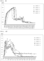
- FIG. 9 is a graph showing the results of measuring the adhesive strengths of Sample 1
- FIG. 10 is a graph showing the results of measuring the adhesive strengths of Sample 3.
- the average adhesive strength of Sample 1 is 3.34 kgf
- the average adhesive strength of Sample 3 is 1.35 kg.
- Sample 1 in which the thickness of the inner resin layer is relatively small, corresponds to the case in which the outer sealed portion of the electrode assembly receiving portion is located in a direction toward the outside of the pouch-shaped battery case
- Sample 2 in which the thickness of the inner resin layer is relatively large, corresponds to the case in which the outer sealing portion of the electrode assembly receiving portion is located in a direction toward the outside of the pouch-type battery case.
- the thickness of the inner resin layer in the pressed portion is gradually decreased from the inside to the outside of the pouch-shaped battery case, whereby the adhesive strength is gradually increased.
- a chamber configured to store Samples 1 to 3 was prepared, the temperature of the chamber was set to specific temperatures, and the samples were placed in the chamber. When the temperature of the chamber reached each of the specific temperatures, the adhesive strength was measured after waiting for 1 minute.
- the specific temperatures were room temperature, 100°C, 110°C, 120°C, and 130°C.
- FIG. 11 is a graph showing adhesive strength based on temperature
- FIG. 12 is a graph showing a change in adhesive strength of Sample 1 to Sample 3.
- (a) shows the highest value of adhesive strength by temperature during an adhesive strength measurement process, and (b) shows the average value of the section at which the adhesive strength was stably measured.
- the adhesive strength of the sealed portion was measured at room temperature, 100°C, 110°C, 120°C, and 130°C.
- the adhesive strength measurement was performed using a method of measuring the adhesion strength over time while separating the adhered parts of the pouch-shaped battery case from the side at which the polyball was located. The section having the highest adhesive strength was measured at the part at which the polyball was formed, which is the beginning of the adhesive strength measurement.
- the highest adhesive strength is measured in Sample 1, in which the thickness of the inner resin layer is small, and it can be seen that the adhesive strength increases with an increase in size of the polyball in consideration of the fact that the size of the polyball is large at the part at which the thickness of the inner resin layer is small.
- the size of the polyball formed at the inside of the pouch-shaped battery case is reduced, whereby it is possible to provide a pouch-shaped battery cell with lower adhesive strength of a sealed portion.
Landscapes
- Engineering & Computer Science (AREA)
- Mechanical Engineering (AREA)
- Chemical & Material Sciences (AREA)
- Chemical Kinetics & Catalysis (AREA)
- Electrochemistry (AREA)
- General Chemical & Material Sciences (AREA)
- Physics & Mathematics (AREA)
- Thermal Sciences (AREA)
- Inorganic Chemistry (AREA)
- Toxicology (AREA)
- Health & Medical Sciences (AREA)
- Manufacturing & Machinery (AREA)
- Sealing Battery Cases Or Jackets (AREA)
Abstract
Description
- This application claims the benefit of priority to
Korean Patent Application No. 10-2022-0088274 filed on July 18, 2022 Korean Patent Application No. 10-2023-0093018 filed on July 18, 2023 - The present invention relates to a pouch-shaped battery cell and an apparatus for sealing a pouch-shaped battery case used to manufacture the same. More particularly, the present invention relates to a pouch-shaped battery cell capable of rapidly discharging gas when the internal pressure of the pouch-shaped battery cell increases, whereby explosion of the pouch-shaped battery cell is prevented, and an apparatus for sealing a pouch-shaped battery case used to manufacture the same.
- A lithium secondary battery, which is capable of being charged and discharged, has been widely used as an energy source for wireless mobile devices or wearable devices, which are worn on bodies, and has also been used as an energy source for electric vehicles and hybrid electric vehicles presented as alternatives to existing gasoline and diesel vehicles, which cause air pollution.
- The lithium secondary battery may be classified as a prismatic battery cell including a metal can-shaped case, a cylindrical battery cell including a metal can-shaped case, or a pouch-shaped battery cell including a case formed of a laminate sheet. Thereamong, the pouch-shaped battery cell is mostly used due to easy deformation and an increase in energy density when stored and stacked.
- In the lithium secondary battery, a side reaction occurs between the surface of an electrode and an electrolytic solution during repeated charging and discharging, and if gas generated at this time is not discharged from the battery case, the battery case may swell, whereby the battery case may be deformed.
- In particular, since the pouch-shaped battery cell includes no separate venting structure, unlike the cylindrical battery cell, which includes a safety vent, venting may occur at a part of a thermally fused outer periphery at which gas is concentrated or adhesion due to thermal fusion is low.
- In general, the pouch-shaped battery cell is manufactured by shaping a laminated sheet including an outer coating layer, a metal layer, and an inner resin layer into a pouch-shaped battery case, receiving an electrode assembly in the pouch-shaped battery case, and sealing the pouch-shaped battery case.
- The laminate sheet may have a more complex and varied layered structure depending on implementation of the laminate sheet and the environment to which the laminate sheet is applied.
- In order to seal the pouch-shaped battery case, an outer periphery of the pouch-shaped battery case is pressed using a heating block configured to provide heat and pressure. As a result, the inner resin layer is melted, whereby inner resin layers of an upper case and a lower case, which are stacked on top of each other, are thermally fused to form a seal.
- Conventionally, the heating block presses the entirety of the outer periphery of the pouch-shaped battery case with uniform force, whereby adhesion of the entirety of a sealed portion is uniform.
- In this case, the pouch-shaped battery case is difficult to vent even though the internal pressure of the pouch-shaped battery cell increases, whereby the pressure in the pouch-shaped battery case gradually increases.
- If external impact is applied to the pouch-shaped battery case while the pouch-shaped battery case continuously swells or if thermal runaway occurs as the result of a chemical chain reaction due to electrical short circuit, the pouch-shaped battery cell may explode.
- Therefore, there is a need to develop a pouch-shaped battery cell configured such that the sealing pressure of a sealed portion formed at an outer periphery of a pouch-shaped battery case is nonuniform, whereby venting easily occurs or sequential venting occurs, and therefore explosion of the pouch-shaped battery cell is prevented and external materials are prevented from being introduced into the pouch-shaped battery cell in the process, and an apparatus for sealing a pouch-shaped battery case used to manufacture the same.
- The present invention has been made in view of the above problems, and it is an object of the present invention to provide a pouch-shaped battery cell configured such that a sealed portion of the pouch-shaped battery cell is formed so as to have different adhesive forces, whereby penetration of moisture, etc. into the pouch-shaped battery cell is prevented while venting is sequentially performed, and an apparatus for sealing a pouch-shaped battery case used to manufacture the same.
- A pouch-shaped battery cell according to the present invention to accomplish the above object includes a pouch-shaped battery case including a laminated sheet including a resin layer and a metal layer and an electrode assembly accommodated in the pouch-shaped battery case, wherein a sealed portion is formed at an outer periphery of an electrode assembly receiving portion and the sealed portion is sealed by a thermal fusion, the sealed portion is formed such that pressed portions and non-pressed portions are alternately disposed in a direction from the inside of the pouch-shaped battery case to the outside of the pouch-shaped battery case, and the sealing force of each of the pressed portions increases along the direction toward the outside of the pouch-shaped battery case.
- When the internal pressure of the pouch-shaped battery case increases, adhesive states of the pressed portions may be sequentially released in the direction from the inside to the outside of the pouch-shaped battery case.
- The pouch-shaped battery case may include an inner resin layer, a metal layer, and an outer coating layer, and a thickness of the metal layer in each of the pressed portions may be less than the thickness of the metal layer in each of the non-pressed portions.
- The thickness of the metal layer in each of the pressed portions of the sealed portion may decrease along the direction toward the outside of the pouch-shaped battery case.
- The present invention provides an apparatus for sealing a pouch-shaped battery case used to manufacture the pouch-shaped battery cell, the apparatus including a lower sealing member located under the pouch-shaped battery case and an upper sealing member located above the pouch-shaped battery case, wherein the upper sealing member includes a plurality of sealing tools spaced apart from each other, wherein each of the plurality of sealing tools is configured to have a pressing force being different from each other.
- The pressing force of each of the plurality of sealing tools may be configured to increase along the direction toward the outside of the pouch-shaped battery case.
- Each of the plurality of sealing tools may be configured to have a temperature being different from each other.
- The temperature of each of the plurality of sealing tools may be configured to increase along the direction toward the outside of the pouch-shaped battery case.
- The plurality of sealing tools may have a same length being the same.
- An upper surface of the lower sealing member may be flat and may be disposed to face the pouch-shaped battery case.
- The lower sealing member may be configured to be heated.
- The plurality of sealing tools may be configured to sequentially pressing along a direction from a sealing tool disposed at the inside of the pouch-shaped battery case to a sealing tool disposed at the outside of the pouch-shaped battery case.
- Each of the plurality of sealing tools may be divided into two or more regions in an overall length direction, and each of the two or more regions may be configured to separately adjust at least one of the pressing temperature and the pressing pressure.
- A pressing surface of each of the plurality of sealing tools may be inclined.
- In addition, the present invention may provide various combinations of the above solving means.
- As is apparent from the above description, in the present invention, venting of a sealed portion of a pouch-shaped battery cell is sequentially performed in a direction from the inside to the outside of a pouch-shaped battery case, whereby it is possible to accommodate an increase in volume of the pouch-shaped battery case and to prevent external materials from being introduced into the pouch-shaped battery case.
- In addition, the pressing temperature and pressing force of a plurality of sealing tools constituting an upper sealing member are designed to be increased from the inside to the outside of the pouch-shaped battery case, whereby it is possible to reduce the size of a polyball formed at the inside of the pouch-shaped battery case as the result of melting of an inner resin layer of the pouch-shaped battery case, and therefore the pouch-shaped battery case may be vented even at a low internal pressure.
-
-
FIG. 1 is a vertical sectional view showing the state in which an apparatus for sealing a pouch-shaped battery case according to a first embodiment is disposed at a part of a pouch-shaped battery case to be sealed. -
FIG. 2 is a perspective view and a partial enlarged view ofFIG. 1 . -
FIG. 3 is a perspective view of an apparatus for sealing a pouch-shaped battery case according to a second embodiment. -
FIG. 4 is a perspective view and a partial enlarged view of a pouch-shaped battery cell sealed using the apparatus for sealing the pouch-shaped battery case ofFIG. 3 . -
FIG. 5 is a vertical sectional view showing the state in which an apparatus for sealing a pouch-shaped battery case according to a third embodiment is disposed at a part of a pouch-shaped battery case to be sealed. -
FIG. 6 is a vertical sectional view of a sealed portion of a pouch-shaped battery cell sealed using the apparatus for sealing the pouch-shaped battery case ofFIG. 5 . -
FIG. 7 is a perspective view of an apparatus for sealing a pouch-shaped battery case according to a fourth embodiment. -
FIG. 8 shows polyballs in pouch-shaped battery cells according to Example and Comparative Example. -
FIG. 9 is a graph showing the results of measuring the adhesive strength ofSample 1. -
FIG. 10 is a graph showing the results of measuring the adhesive strength ofSample 3. -
FIG. 11 is a graph showing sealing strength based on temperature. -
FIG. 12 is a graph showing a change in adhesive strength ofSample 1 toSample 3. - Now, preferred embodiments of the present invention will be described in detail with reference to the accompanying drawings such that the preferred embodiments of the present invention can be easily implemented by a person having ordinary skill in the art to which the present invention pertains. In describing the principle of operation of the preferred embodiments of the present invention in detail, however, a detailed description of known functions and configurations incorporated herein will be omitted when the same may obscure the subject matter of the present invention.
- In addition, the same reference numbers will be used throughout the drawings to refer to parts that perform similar functions or operations. In the case in which one part is said to be connected to another part throughout the specification, not only may the one part be directly connected to the other part, but also, the one part may be indirectly connected to the other part via a further part. In addition, that a certain element is included does not mean that other elements are excluded, but means that such elements may be further included unless mentioned otherwise.
- In addition, a description to embody elements through limitation or addition may be applied to all inventions, unless particularly restricted, and does not limit a specific invention.
- Also, in the description of the invention and the claims of the present application, singular forms are intended to include plural forms unless mentioned otherwise.
- Also, in the description of the invention and the claims of the present application, "or" includes "and" unless mentioned otherwise. Therefore, "including A or B" means three cases, namely, the case including A, the case including B, and the case including A and B.
- Embodiments of the present invention will be described in detail with reference to the accompanying drawings.
-
FIG. 1 is a vertical sectional view showing the state in which an apparatus for sealing a pouch-shaped battery case according to a first embodiment is disposed at a part of a pouch-shaped battery case to be sealed, andFIG. 2 is a perspective view and a partial enlarged view ofFIG. 1 . - Referring to
FIGs. 1 and 2 , the apparatus for sealing the pouch-shaped battery case according to the present invention includes alower sealing member 300 located under a pouch-shaped battery case upper sealing member 200 located above the pouch-shaped battery case upper sealing member 200 includes a plurality of sealing tools having different pressing forces when sealing is performed, and the plurality of sealing tools is disposed spaced apart from each other. - The plurality of sealing tools shown in
FIGs. 1 and 2 is constituted by afirst sealing tool 210, asecond sealing tool 220, and athird sealing tool 230, wherein the three sealing tools are separate members, which may press the pouch-shaped battery case in a state of being disposed spaced apart from each other at regular intervals. - The plurality of sealing tools may be set such that pressing force is gradually increased in the order of the
first sealing tool 210, thesecond sealing tool 220, and thethird sealing tool 230, and the distance between theupper sealing member 200 and thelower sealing member 300 is gradually decreased toward the outside of the pouch-shaped battery case. - As a result, the pouch-shaped
battery case - For example, the range of the pressing force of the plurality of sealing tools may be set to a range within which the pouch-shaped battery case is not damaged, and may be specifically 100 kgf or less, more specifically 20 kgf to 80 kgf. Within the above range, the pressing force deviation between the
first sealing tool 210 and thesecond sealing tool 220, and the pressing force deviation between thesecond sealing tool 220 and thethird sealing tool 230 may be set so as to be equal to each other or to be different from each other. - Meanwhile, the plurality of sealing tools may be set so as to have different temperatures.
- Specifically, the temperatures of the
first sealing tool 210, thesecond sealing tool 220, and thethird sealing tool 230 may be set so as to be increased in that order. For example, the temperature range of the sealing tools may be set to a range within which an inner resin layer of the pouch-shaped battery case can be melted, and may be specifically 130°C to 200°C, more specifically 140°C to 180°C, which is a range within which polypropylene, which is widely used as a material for the inner resin layer of the pouch-shaped battery case, can be melted. Within the above range, the temperature deviation between thefirst sealing tool 210 and thesecond sealing tool 220 and the temperature deviation between thesecond sealing tool 220 and thethird sealing tool 230 may be set so as to be equal to each other or to be different from each other. - That is, since the temperatures of the sealing tools are gradually increased toward the outside of the pouch-shaped
battery case battery cases - As described above, the pressures and the temperatures of the plurality of sealing tools of the
upper sealing member 200 according to the present invention may be individually set, and the lengths H of thefirst sealing tool 210, thesecond sealing tool 220, and thethird sealing tool 230 may be equal to each other. - That is, since the pressures and the temperatures of the
first sealing tool 210, thesecond sealing tool 220, and thethird sealing tool 230 may be individually set so as to be different from each other even though the lengths H thereof are equal to each other, it is possible to form a sealed portion having sealing forces different depending on the position when the pouch-shaped battery case is sealed. - An upper surface of the
lower sealing member 300, which faces the pouch-shapedbattery case lower sealing member 300 may support the entirety of the sealed portion of the pouch-shaped battery case. - In addition, the
lower sealing member 300 may be configured in a heatable form to heat a lower surface of the pouch-shapedbattery case - Specifically, the temperature of the lower sealing member may be set within the temperature range of the
upper sealing member 200, and may be set to, for example, a temperature equal to the temperature of the first sealing tool of theupper sealing member 200, which has the lowest temperature. - The plurality of sealing tools may sequentially perform pressing in a direction from the
first sealing tool 210, which is disposed at the inside of the pouch-shaped battery case, to thethird sealing tool 230, which is disposed at the outside of the pouch-shaped battery case. - When a part of the pouch-shaped battery case to be sealed is pressed and heated, the inner resin layer at the part to be sealed is melted and moved toward inner and outer ends of the part to be sealed, which are opposite ends of the part to be sealed. When solidified in this state, the molten inner resin layer becomes a round ball-shaped lump. In the specification of the present application, the lump is called a polyball.
- The larger the size of the polyball, the more difficult it is to vent the battery case.
- In the present invention, therefore, the
first sealing tool 210, thesecond sealing tool 220, and thethird sealing tool 230 may perform pressing in that order to move the molten inner resin layer to the outside of the pouch-shaped battery case, whereby it is possible to reduce the size of the polyball formed at the inside of the sealed portion of the pouch-shaped battery case. Consequently, it is possible to reduce the pressure required to vent the pouch-shaped battery case. - Although
FIG. 2 shows the form in which only an outer periphery of one side of the pouch-shaped battery case is pressed using the apparatus for sealing the pouch-shaped battery case according to the first embodiment, it is obvious that a sealed portion may be formed at any of four outer peripheries of the pouch-shaped battery case using the apparatus for sealing the pouch-shaped battery case according to the first embodiment. This is equally applied to an apparatus for sealing a pouch-shaped battery case according to each of third and fourth embodiments, which is configured to have a straight structure. -
FIG. 3 is a perspective view of an apparatus for sealing a pouch-shaped battery case according to a second embodiment. - Referring to
FIG. 3 , the apparatus for sealing the pouch-shaped battery case according to the second embodiment includes anupper sealing member 200, which includes afirst sealing tool 210, asecond sealing tool 220, and athird sealing tool 230, and alower sealing member 300. - Each of the
first sealing tool 210, thesecond sealing tool 220, and thethird sealing tool 230 is configured in the form of a square ring. When the first sealing tool, the second sealing tool, and the third sealing tool are disposed so as to overlap each other, a gap is formed between thefirst sealing tool 210 and thesecond sealing tool 220, and a gap is formed between thesecond sealing tool 220 and thethird sealing tool 230. - That is, a pouch-shaped battery case is not directly pressed by the gap.
- The
first sealing tool 210, thesecond sealing tool 220, and thethird sealing tool 230 may sequentially perform pressing in a direction from thefirst sealing tool 210, which is disposed at the inside of the pouch-shaped battery case, to thethird sealing tool 230, which is disposed at the outside of the pouch-shaped battery case, to move a molten inner resin layer to the outside of the pouch-shaped battery case, whereby it is possible to reduce the size of a polyball formed at the inside of a sealed portion of the pouch-shaped battery case. Consequently, it is possible to reduce the pressure required to vent the pouch-shaped battery case. -
FIG. 4 is a perspective view and a partial enlarged view of a pouch-shaped battery cell sealed using the apparatus for sealing the pouch-shaped battery case ofFIG. 3 . - Referring to
FIG. 4 , the pouch-shaped battery cell according to the present invention includes a pouch-shapedbattery case battery case - The pouch-shaped battery case includes an outer coating layer that is highly resistant to an external environment, a metal layer configured to prevent introduction of foreign matter, such as gas or moisture, or leakage of an electrolytic solution, and an inner resin layer that is thermally fusible.
- The outer coating layer may include polyethylene terephthalate or stretched nylon; aluminum or an aluminum alloy may be used as the metal layer; and the inner resin layer may include polypropylene.
- The pressed portions include a first pressed
portion 131, a second pressedportion 132, and a thirdpressed portion 133, and the non-pressed portions include a firstnon-pressed portion 141 and a secondnon-pressed portion 142. - The first pressed
portion 131, the second pressedportion 132, and the thirdpressed portion 133 are parts pressed respectively by thefirst sealing tool 210, thesecond sealing tool 220, and thethird sealing tool 230 of theupper sealing member 200 ofFIG. 3 . - When the pressing forces and pressing temperatures of the
first sealing tool 210, thesecond sealing tool 220, and thethird sealing tool 230 are set so as to be gradually increased toward the outside of the pouch-shaped battery case, the adhesion of the thirdpressed portion 133 is the highest among the first pressedportion 131, the second pressedportion 132, and the thirdpressed portion 133. - When the internal pressure of the pouch-shaped
battery case battery case battery case - Specifically, when the adhesive state of the first pressed
portion 131 is released, the internal space of the pouch-shaped battery case may extend to the firstnon-pressed portion 141, whereby it is possible to buffer an increase in internal pressure. Subsequently, when the adhesive state of the second pressedportion 132 is released, the internal space of the pouch-shaped battery case may extend to the secondnon-pressed portion 142, whereby it is possible to buffer an increase in internal pressure. Consequently, it is possible to prevent the pouch-shaped battery case from instantaneously exploding due to an increase in internal pressure. At this time, the pressed state of the thirdpressed portion 133 is maintained, and therefore it is possible to prevent the introduction of external materials, such as moisture, into the pouch-shaped battery cell. - In addition, the thickness of the second pressed
portion 132 is formed so as to be less than the thickness of the first pressedportion 131, and the thickness of the thirdpressed portion 133 is formed so as to be less than the thickness of the second pressedportion 132. - At this time, the thicknesses of the first pressed
portion 131, the second pressedportion 132, and the thirdpressed portion 133 may be reduced due to a decrease in thickness of each of the inner resin layer, the metal layer, and the outer coating layer, specifically due to a decrease in thickness of the metal layer. - That is, the thickness of the metal layer in the first pressed
portion 131, the second pressedportion 132, and the thirdpressed portion 133 of the sealed portion of the pouch-shaped battery case may be gradually decreased in a direction toward the outside of the pouch-shaped battery case. - As a result, the thickness of the metal layer in the third
pressed portion 133 may be reduced to the extent to which rigidity cannot be expected. When the second pressedportion 132 is vented, therefore, the adhesive state of the thirdpressed portion 133 may not be maintained, whereby the thirdpressed portion 133 may be torn under venting pressure, and therefore the pouch-shaped battery case may be completely opened. - Meanwhile, since the first
non-pressed portion 141 and the secondnon-pressed portion 142 are parts that are not pressed by the upper sealing member, the original thickness of the pouch-shaped battery case may be maintained. Therefore, the thickness of the metal layer in the first pressedportion 131, the second pressedportion 132, and the thirdpressed portion 133 is formed so as to be less than the thickness of the metal layer in the firstnon-pressed portion 141 and the secondnon-pressed portion 142. -
FIG. 5 is a vertical sectional view showing the state in which an apparatus for sealing a pouch-shaped battery case according to a third embodiment is disposed at a part of a pouch-shaped battery case to be sealed. - Referring to
FIG. 5 , the apparatus for sealing the pouch-shaped battery case according to the third embodiment is configured such that a pressing surface of each of afirst sealing tool 210, asecond sealing tool 220, and athird sealing tool 230 is inclined. InFIG. 5 , the inclination of the pressing surface is exaggerated for the convenience of explanation, and the difference between the largest length H and the smallest length of each sealing tool is less than the sum of the thicknesses of the pouch-shapedbattery cases - The left side of each of the
first sealing tool 210, thesecond sealing tool 220, and thethird sealing tool 230, the length H of which is large, presses the pouch-shapedbattery case battery case first sealing tool 210, thesecond sealing tool 220, and thethird sealing tool 230 may have higher sealing force than the sealed portion of the pouch-shapedbattery case -
FIG. 6 is a vertical sectional view of a sealed portion of a pouch-shaped battery cell sealed using the apparatus for sealing the pouch-shaped battery case ofFIG. 5 . - Referring to
FIG. 6 , a pressed portion includes a first pressedportion 131, a second pressedportion 132, and a thirdpressed portion 133, and a non-pressed portion includes a firstnon-pressed portion 141 and a secondnon-pressed portion 142. - The first pressed
portion 131, the second pressedportion 132, and the thirdpressed portion 133 are parts pressed respectively by thefirst sealing tool 210, thesecond sealing tool 220, and thethird sealing tool 230 of theupper sealing member 200 ofFIG. 5 . - When the pressing forces and pressing temperatures of the
first sealing tool 210, thesecond sealing tool 220, and thethird sealing tool 230 are set so as to be gradually increased toward the outside of a pouch-shaped battery case, the adhesion of the thirdpressed portion 133 is the highest among the first pressedportion 131, the second pressedportion 132, and the thirdpressed portion 133. - When the internal pressure of the pouch-shaped
battery case battery case - The first pressed
portion 131, the second pressedportion 132, and the thirdpressed portion 133 are pressed by the upper sealing member, the pressing surface of which is inclined, shown inFIG. 5 , and therefore the thickness of each of the first pressedportion 131, the second pressedportion 132, and the thirdpressed portion 133 is gradually increased from the inside to the outside of the pouch-shaped battery case. - Consequently, a molten inner resin layer may move from the first pressed
portion 131 to the firstnon-pressed portion 141, and may move from the second pressedportion 132 to the secondnon-pressed portion 142, whereby it is possible to reduce the size of a polyball formed at the inside of the first pressedportion 131. - In connection with the difference in thickness of the metal layer of the pouch-shaped battery case, the description of the pouch-shaped battery cell shown in
FIG. 4 may be equally applied to the description of the sealed portion of the pouch-shaped battery cell shown inFIG. 6 . -
FIG. 7 is a perspective view of an apparatus for sealing a pouch-shaped battery case according to a fourth embodiment. - Referring to
FIG. 7 , each of a plurality of sealing tools including anupper sealing member 200 may be divided into two or more regions in an overall length direction L, and at least one of pressing temperature and pressing pressure of each region may be separately adjusted, when compared to the apparatus for sealing the pouch-shaped battery case shown inFIG. 2 . - In
FIG. 7 , theupper sealing member 200 is configured such that afirst sealing tool 210 is divided into afirst region 211 and asecond region 212, asecond sealing tool 220 is divided into afirst region 221 and asecond region 222, and athird sealing tool 230 is divided into afirst region 231 and asecond region 232. - In external appearance, the
first regions second regions second regions - The
first sealing tool 210, thesecond sealing tool 220, and thethird sealing tool 230 may sequentially seal the pouch-shaped battery case, or any of thefirst regions second regions - Hereinafter, the present invention will be described with reference to examples. The examples are provided only for easier understanding of the present invention and should not be construed as limiting the scope of the present invention.
- A pouch-shaped battery case including an outer coating layer, a metal layer, and an inner resin layer was prepared, and an outer periphery of one side of the pouch-shaped battery case was pressed and heated using the apparatus for sealing the pouch-shaped battery case shown in
FIGs. 1 and 2 . - At this time, the pressing forces and pressing temperatures of the first sealing tool, the second sealing tool, and the third sealing tool were set as shown in Table 1 below, and the temperature of the lower sealing member was set to 140°C, and the first sealing tool, the second sealing tool, and the third sealing tool performed pressing in that order.
[Table 1] Pressing force (kgf) Pressing temperature (°C) First sealing tool 20 140 Second sealing tool 30 160 Third sealing tool 80 180 - A pouch-shaped battery case identical to Example was prepared, the pressing force and the pressing temperature of each of an upper sealing member having a flat pressing surface and a lower sealing member were set to 40 kgf and 180°C, respectively, and an outer periphery of one side of the pouch-shaped battery case was pressed and heated.
-
FIG. 8 shows polyballs in pouch-shaped battery cells according to Example and Comparative Example. - Referring to
FIG. 8 , (a) shows the result of Comparative Example and (b) is the result of Example. It can be seen that the size of thepolyball 400 is significantly reduced when the apparatus for sealing the pouch-shaped battery case, as in Example, is used. As a result, the pouch-shapedbattery case 100 may be easily vented at a lower pressure, and therefore it is possible to prevent explosion of the pouch-shaped battery cell. - An electrode assembly was received in a pouch-shaped battery case having a thickness of 71 um, and an outer periphery of the pouch-shaped battery case was sealed, whereby a pouch-shaped battery cell was manufactured.
- At this time, the outer periphery of the pouch-shaped battery case was sealed under three sealing conditions: 40 kgf, 185°C, and pressing for 2 seconds; 40 kgf, 170°C, and pressing for 2 seconds; and 40 kgf, 150°C, and pressing for 2 seconds to manufacture five pouch-shaped battery cells each having a thickness of a sealed portion of 127 µm, five pouch-shaped battery cells each having a thickness of a sealed portion of 132 um, and five pouch-shaped battery cells each having a thickness of a sealed portion of 137 µm. The pouch-shaped battery cells each having a thickness of a sealed portion of 127 µm are grouped into
Sample 1, the pouch-shaped battery cells each having a thickness of a sealed portion of 132 um are grouped intoSample 2, and the pouch-shaped battery cells each having a thickness of a sealed portion of 137 µm are grouped intoSample 3. - The sealed portions of the pouch-shaped battery cells of
Sample 1 andSample 3 were cut, and the thickness of the inner resin layer of each of the pouch-shaped battery cells was measured on the cut surfaces. - The average thickness of the inner resin layers of
Sample 1 is 33.2 um, and the average thickness of the inner resin layers ofSample 3 is 42.31 µm. - The adhesive strengths of
Sample 1 andSample 3 were measured. -
FIG. 9 is a graph showing the results of measuring the adhesive strengths ofSample 1, andFIG. 10 is a graph showing the results of measuring the adhesive strengths ofSample 3. - Referring to
FIGs. 9 and 10 , the average adhesive strength ofSample 1 is 3.34 kgf, and the average adhesive strength ofSample 3 is 1.35 kg. - Consequently, it can be seen that, when the sealed portion is configured so as to have different sealing forces, as in the present invention,
Sample 1, in which the thickness of the inner resin layer is relatively small, corresponds to the case in which the outer sealed portion of the electrode assembly receiving portion is located in a direction toward the outside of the pouch-shaped battery case, andSample 2, in which the thickness of the inner resin layer is relatively large, corresponds to the case in which the outer sealing portion of the electrode assembly receiving portion is located in a direction toward the outside of the pouch-type battery case. - That is, it can be expected that the thickness of the inner resin layer in the pressed portion is gradually decreased from the inside to the outside of the pouch-shaped battery case, whereby the adhesive strength is gradually increased.
- A chamber configured to store
Samples 1 to 3 was prepared, the temperature of the chamber was set to specific temperatures, and the samples were placed in the chamber. When the temperature of the chamber reached each of the specific temperatures, the adhesive strength was measured after waiting for 1 minute. - The specific temperatures were room temperature, 100°C, 110°C, 120°C, and 130°C.
-
FIG. 11 is a graph showing adhesive strength based on temperature, andFIG. 12 is a graph showing a change in adhesive strength ofSample 1 toSample 3. - Referring to
FIG. 11 , (a) shows the highest value of adhesive strength by temperature during an adhesive strength measurement process, and (b) shows the average value of the section at which the adhesive strength was stably measured. - Referring to
FIG. 12 , the adhesive strength of the sealed portion was measured at room temperature, 100°C, 110°C, 120°C, and 130°C. - The adhesive strength measurement was performed using a method of measuring the adhesion strength over time while separating the adhered parts of the pouch-shaped battery case from the side at which the polyball was located. The section having the highest adhesive strength was measured at the part at which the polyball was formed, which is the beginning of the adhesive strength measurement.
- Referring to (a) and (b) of
FIG. 11 , it can be seen that the larger the thickness of the inner resin layer, the lower the adhesive strength and that the higher the temperature of the chamber, the lower the adhesive strength. Referring toFIG. 12 , it can be seen that the maximum adhesive force was measured at the part at which the polyball was formed, which is the beginning of the adhesive strength measurement, under all temperature conditions. - That is, the highest adhesive strength is measured in
Sample 1, in which the thickness of the inner resin layer is small, and it can be seen that the adhesive strength increases with an increase in size of the polyball in consideration of the fact that the size of the polyball is large at the part at which the thickness of the inner resin layer is small. - Consequently, it can be seen that, when the plurality of sealing tools is set so as to have different pressing forces such that the thickness of the inner resin layer is formed so as to be gradually decreased toward the outside of the pouch-shaped battery case, the adhesive strength gradually increases toward the outside of the pouch.
- In addition, when sealing is sequentially performed in a direction from the inside to the outside of the sealed portion of the pouch-shaped battery case, as in the present invention, the size of the polyball formed at the inside of the pouch-shaped battery case is reduced, whereby it is possible to provide a pouch-shaped battery cell with lower adhesive strength of a sealed portion.
- Those skilled in the art to which the present invention pertains will appreciate that various applications and modifications are possible within the category of the present invention based on the above description.
-
- 100, 110, 120: Pouch-shaped battery cases
- 131: First pressed portion
- 132: Second pressed portion
- 133: Third pressed portion
- 141: First non-pressed portion
- 142: Second non-pressed portion
- 200: Upper sealing member
- 210: First sealing tool
- 220: Second sealing tool
- 230: Third sealing tool
- 300: Lower sealing member
- 400: Polyball
Claims (15)
- A pouch-shaped battery cell comprising:a pouch-shaped battery case including a laminated sheet comprising an inner resin layer, a metal layer, and an outer coating layer; andan electrode assembly accommodated in the pouch-shaped battery case,wherein a sealed portion is formed at an outer periphery of an electrode assembly receiving portion, wherein the sealed portion is sealed by a thermal fusion,wherein the sealed portion is formed such that pressed portions and non-pressed portions are alternately disposed in a direction from an inside of the pouch-shaped battery case to an outside of the pouch-shaped battery case, andwherein a thickness of the inner resin layer of each of the pressed portions decreases along the direction toward the outside of the pouch-shaped battery case.
- The pouch-shaped battery cell according to claim 1, wherein, when an internal pressure of the pouch-shaped battery case increases, adhesive states of the pressed portions are sequentially released in the direction from the inside to the outside of the pouch-shaped battery case.
- The pouch-shaped battery cell according to claim 1, wherein a thickness of the metal layer in each of the pressed portions is less than a thickness of the metal layer in each of the non-pressed portions.
- The pouch-shaped battery cell according to claim 3, wherein the thickness of the metal layer in each of the pressed portions of the sealed portion decreases along the direction toward the outside of the pouch-shaped battery case.
- The pouch-shaped battery cell according to claim 1, wherein a sealing force of each of the pressed portions increases along the direction toward the outside of the pouch-shaped battery case.
- An apparatus for sealing a pouch-shaped battery case used to manufacture the pouch-shaped battery cell according to any one of claims 1 to 5, the apparatus comprising:a lower sealing member located under the pouch-shaped battery case; andan upper sealing member located above the pouch-shaped battery case,wherein the upper sealing member comprises a plurality of sealing tools spaced apart from each other, wherein each of the plurality of sealing tools is configured to have a pressing force being difference from each other.
- The apparatus according to claim 6, wherein the pressing force of each of the plurality of sealing tools is configured to increase along the direction toward an outside of the pouch-shaped battery case.
- The apparatus according to claim 6, wherein each of the plurality of sealing tools is configured to have a temperature being different from each other.
- The apparatus according to claim 6, wherein a temperature of each of the plurality of sealing tools is configured to increase along the direction toward an outside of the pouch-shaped battery case.
- The apparatus according to claim 6, wherein the plurality of sealing tools has a length being the same.
- The apparatus according to claim 6, wherein an upper surface of the lower sealing member is flat and is disposed to face the pouch-shaped battery case.
- The apparatus according to claim 11, wherein the lower sealing member is configured to be heated.
- The apparatus according to claim 6, wherein the plurality of sealing tools is configured to sequentially pressing along a direction from a sealing tool disposed at an inside of the pouch-shaped battery case to a sealing tool disposed at an outside of the pouch-shaped battery case.
- The apparatus according to claim 6, wherein each of the plurality of sealing tools is divided into two or more regions in an overall length direction, and
wherein each of the two or more regions is configured to separately adjust at least one of a pressing temperature and a pressing pressure. - The apparatus according to claim 6, wherein a pressing surface of each of the plurality of sealing tools is inclined.
Applications Claiming Priority (2)
| Application Number | Priority Date | Filing Date | Title |
|---|---|---|---|
| KR20220088274 | 2022-07-18 | ||
| PCT/KR2023/010311 WO2024019485A1 (en) | 2022-07-18 | 2023-07-18 | Pouch-type battery cell and pouch-type battery case sealing device for manufacturing same |
Publications (2)
| Publication Number | Publication Date |
|---|---|
| EP4404362A1 true EP4404362A1 (en) | 2024-07-24 |
| EP4404362A4 EP4404362A4 (en) | 2025-08-27 |
Family
ID=89721836
Family Applications (1)
| Application Number | Title | Priority Date | Filing Date |
|---|---|---|---|
| EP23843331.2A Pending EP4404362A4 (en) | 2022-07-18 | 2023-07-18 | Bag-type battery cell and bag-type battery case sealing device for producing the same |
Country Status (3)
| Country | Link |
|---|---|
| EP (1) | EP4404362A4 (en) |
| KR (1) | KR20240011113A (en) |
| CN (1) | CN118382961A (en) |
Family Cites Families (6)
| Publication number | Priority date | Publication date | Assignee | Title |
|---|---|---|---|---|
| JP4498514B2 (en) * | 2000-01-18 | 2010-07-07 | 大日本印刷株式会社 | Battery container |
| KR100571269B1 (en) * | 2004-09-22 | 2006-04-13 | 삼성에스디아이 주식회사 | Pouches for secondary batteries and pouch type secondary batteries |
| CN104584259B (en) * | 2012-12-28 | 2017-03-15 | 株式会社Lg 化学 | Apparatus and method for the bag-shaped housing of sealed secondary battery |
| KR101793729B1 (en) * | 2014-12-24 | 2017-11-03 | 주식회사 엘지화학 | Pouch type secondary battery and a method of making the same |
| KR20170026230A (en) * | 2015-08-27 | 2017-03-08 | 주식회사 엘지화학 | apparatus for sealing secondary battery |
| KR101940150B1 (en) * | 2015-12-11 | 2019-01-18 | 주식회사 엘지화학 | Sealing apparatus for secondary battery |
-
2023
- 2023-07-18 EP EP23843331.2A patent/EP4404362A4/en active Pending
- 2023-07-18 CN CN202380014677.8A patent/CN118382961A/en active Pending
- 2023-07-18 KR KR1020230093018A patent/KR20240011113A/en active Pending
Also Published As
| Publication number | Publication date |
|---|---|
| CN118382961A (en) | 2024-07-23 |
| EP4404362A4 (en) | 2025-08-27 |
| KR20240011113A (en) | 2024-01-25 |
Similar Documents
| Publication | Publication Date | Title |
|---|---|---|
| EP3566853B1 (en) | Pouch forming method and apparatus | |
| EP3249732B1 (en) | Sealing apparatus of pouch-type rechargeable battery | |
| KR101049841B1 (en) | Curved battery cell and battery pack comprising the same | |
| CN101512821B (en) | Secondary battery including a one-way exhaust valve | |
| EP3373374B1 (en) | Method for sealing pouch case of secondary battery | |
| EP3637492B1 (en) | Crack-prevention sealing block for pouch-shaped secondary batteries, pouch-shaped battery case manufactured using the same, and method of sealing pouch-shaped battery case | |
| KR101826894B1 (en) | Electrode assembly and apparatus for manufacturing the same | |
| US10862099B2 (en) | Apparatus for enhancing electrolyte wetting in rechargeable battery and electrolyte wetting enhancing method using the same | |
| KR20110073405A (en) | Curved battery cell and battery pack comprising the same | |
| EP4357100B1 (en) | Molding apparatus, molding method | |
| US20260074359A1 (en) | Method of Manufacturing Pouch-Shaped Battery Case Having Venting Guide Portion Formed Therein and Pouch-Shaped Battery Case Manufactured by the Method | |
| US20240097245A1 (en) | Battery Cell Including Sealed Portion Having Embossed Pattern Formed Thereon and Sealing Block for Manufacturing the Same | |
| KR102784302B1 (en) | Method of manufacturing pouch-type battery cell comprising two-times sealing and pouch-type battery cell manufactured thereby | |
| US20250293356A1 (en) | Pouch-Shaped Battery Cell and Apparatus for Sealing Pouch-Shaped Battery Case Used to Manufacture the Same | |
| EP4261016B1 (en) | Pouch-type battery and sealing device for pouch-type battery | |
| US12057543B2 (en) | Battery cell manufacturing device | |
| EP4106086A1 (en) | Pouch-type battery cell manufacturing method including secondary sealing and pouch-type battery cell manufactured thereby | |
| CN118382961A (en) | Pouch-shaped battery cell and sealing device for pouch-shaped battery case for manufacturing pouch-shaped battery cell | |
| KR102958832B1 (en) | Cylindrical Battery Case Processing Device and Cylindrical Battery Manufacturing Method Using the Same | |
| EP4501592A1 (en) | Pouch-type battery cell sealing device comprising pair of sealing rollers, sealing method using same, and pouch-type battery cell manufactured using same | |
| KR102924155B1 (en) | Pouch sealing device | |
| EP4738502A1 (en) | Secondary battery pressing device and secondary battery pressing method using same | |
| US20250316804A1 (en) | Battery and method of manufacturing battery | |
| US20250385347A1 (en) | Grid-like pattern sealing device and pouch-type battery manufactured using the same | |
| EP4089809A1 (en) | Battery cell and manufacturing apparatus therefor |
Legal Events
| Date | Code | Title | Description |
|---|---|---|---|
| STAA | Information on the status of an ep patent application or granted ep patent |
Free format text: STATUS: THE INTERNATIONAL PUBLICATION HAS BEEN MADE |
|
| PUAI | Public reference made under article 153(3) epc to a published international application that has entered the european phase |
Free format text: ORIGINAL CODE: 0009012 |
|
| STAA | Information on the status of an ep patent application or granted ep patent |
Free format text: STATUS: REQUEST FOR EXAMINATION WAS MADE |
|
| 17P | Request for examination filed |
Effective date: 20240419 |
|
| AK | Designated contracting states |
Kind code of ref document: A1 Designated state(s): AL AT BE BG CH CY CZ DE DK EE ES FI FR GB GR HR HU IE IS IT LI LT LU LV MC ME MK MT NL NO PL PT RO RS SE SI SK SM TR |
|
| A4 | Supplementary search report drawn up and despatched |
Effective date: 20250729 |
|
| RIC1 | Information provided on ipc code assigned before grant |
Ipc: H01M 50/342 20210101AFI20250723BHEP Ipc: H01M 50/184 20210101ALI20250723BHEP Ipc: H01M 50/367 20210101ALI20250723BHEP Ipc: H01M 50/124 20210101ALI20250723BHEP Ipc: H01M 50/119 20210101ALI20250723BHEP Ipc: H01M 50/121 20210101ALI20250723BHEP Ipc: H01M 50/133 20210101ALI20250723BHEP Ipc: B29C 65/00 20060101ALI20250723BHEP |
|
| DAV | Request for validation of the european patent (deleted) | ||
| DAX | Request for extension of the european patent (deleted) |