EP4404359A1 - Pressure-regulating valve for power storage module - Google Patents
Pressure-regulating valve for power storage module Download PDFInfo
- Publication number
- EP4404359A1 EP4404359A1 EP22869718.1A EP22869718A EP4404359A1 EP 4404359 A1 EP4404359 A1 EP 4404359A1 EP 22869718 A EP22869718 A EP 22869718A EP 4404359 A1 EP4404359 A1 EP 4404359A1
- Authority
- EP
- European Patent Office
- Prior art keywords
- power storage
- case
- plug body
- pressure
- storage module
- Prior art date
- Legal status (The legal status is an assumption and is not a legal conclusion. Google has not performed a legal analysis and makes no representation as to the accuracy of the status listed.)
- Pending
Links
Images




Classifications
-
- H—ELECTRICITY
- H01—ELECTRIC ELEMENTS
- H01M—PROCESSES OR MEANS, e.g. BATTERIES, FOR THE DIRECT CONVERSION OF CHEMICAL ENERGY INTO ELECTRICAL ENERGY
- H01M50/00—Constructional details or processes of manufacture of the non-active parts of electrochemical cells other than fuel cells, e.g. hybrid cells
- H01M50/30—Arrangements for facilitating escape of gases
- H01M50/317—Re-sealable arrangements
- H01M50/325—Re-sealable arrangements comprising deformable valve members, e.g. elastic or flexible valve members
-
- F—MECHANICAL ENGINEERING; LIGHTING; HEATING; WEAPONS; BLASTING
- F16—ENGINEERING ELEMENTS AND UNITS; GENERAL MEASURES FOR PRODUCING AND MAINTAINING EFFECTIVE FUNCTIONING OF MACHINES OR INSTALLATIONS; THERMAL INSULATION IN GENERAL
- F16K—VALVES; TAPS; COCKS; ACTUATING-FLOATS; DEVICES FOR VENTING OR AERATING
- F16K15/00—Check valves
- F16K15/14—Check valves with flexible valve members
-
- F—MECHANICAL ENGINEERING; LIGHTING; HEATING; WEAPONS; BLASTING
- F16—ENGINEERING ELEMENTS AND UNITS; GENERAL MEASURES FOR PRODUCING AND MAINTAINING EFFECTIVE FUNCTIONING OF MACHINES OR INSTALLATIONS; THERMAL INSULATION IN GENERAL
- F16K—VALVES; TAPS; COCKS; ACTUATING-FLOATS; DEVICES FOR VENTING OR AERATING
- F16K17/00—Safety valves; Equalising valves, e.g. pressure relief valves
- F16K17/02—Safety valves; Equalising valves, e.g. pressure relief valves opening on surplus pressure on one side; closing on insufficient pressure on one side
-
- F—MECHANICAL ENGINEERING; LIGHTING; HEATING; WEAPONS; BLASTING
- F16—ENGINEERING ELEMENTS AND UNITS; GENERAL MEASURES FOR PRODUCING AND MAINTAINING EFFECTIVE FUNCTIONING OF MACHINES OR INSTALLATIONS; THERMAL INSULATION IN GENERAL
- F16K—VALVES; TAPS; COCKS; ACTUATING-FLOATS; DEVICES FOR VENTING OR AERATING
- F16K27/00—Construction of housing; Use of materials therefor
-
- F—MECHANICAL ENGINEERING; LIGHTING; HEATING; WEAPONS; BLASTING
- F16—ENGINEERING ELEMENTS AND UNITS; GENERAL MEASURES FOR PRODUCING AND MAINTAINING EFFECTIVE FUNCTIONING OF MACHINES OR INSTALLATIONS; THERMAL INSULATION IN GENERAL
- F16K—VALVES; TAPS; COCKS; ACTUATING-FLOATS; DEVICES FOR VENTING OR AERATING
- F16K27/00—Construction of housing; Use of materials therefor
- F16K27/003—Housing formed from a plurality of the same valve elements
-
- F—MECHANICAL ENGINEERING; LIGHTING; HEATING; WEAPONS; BLASTING
- F16—ENGINEERING ELEMENTS AND UNITS; GENERAL MEASURES FOR PRODUCING AND MAINTAINING EFFECTIVE FUNCTIONING OF MACHINES OR INSTALLATIONS; THERMAL INSULATION IN GENERAL
- F16K—VALVES; TAPS; COCKS; ACTUATING-FLOATS; DEVICES FOR VENTING OR AERATING
- F16K27/00—Construction of housing; Use of materials therefor
- F16K27/02—Construction of housing; Use of materials therefor of lift valves
- F16K27/0209—Check valves or pivoted valves
-
- H—ELECTRICITY
- H01—ELECTRIC ELEMENTS
- H01M—PROCESSES OR MEANS, e.g. BATTERIES, FOR THE DIRECT CONVERSION OF CHEMICAL ENERGY INTO ELECTRICAL ENERGY
- H01M50/00—Constructional details or processes of manufacture of the non-active parts of electrochemical cells other than fuel cells, e.g. hybrid cells
- H01M50/30—Arrangements for facilitating escape of gases
- H01M50/308—Detachable arrangements, e.g. detachable vent plugs or plug systems
-
- H—ELECTRICITY
- H01—ELECTRIC ELEMENTS
- H01M—PROCESSES OR MEANS, e.g. BATTERIES, FOR THE DIRECT CONVERSION OF CHEMICAL ENERGY INTO ELECTRICAL ENERGY
- H01M2200/00—Safety devices for primary or secondary batteries
- H01M2200/20—Pressure-sensitive devices
-
- H—ELECTRICITY
- H01—ELECTRIC ELEMENTS
- H01M—PROCESSES OR MEANS, e.g. BATTERIES, FOR THE DIRECT CONVERSION OF CHEMICAL ENERGY INTO ELECTRICAL ENERGY
- H01M2250/00—Fuel cells for particular applications; Specific features of fuel cell system
- H01M2250/20—Fuel cells in motive systems, e.g. vehicle, ship, plane
-
- Y—GENERAL TAGGING OF NEW TECHNOLOGICAL DEVELOPMENTS; GENERAL TAGGING OF CROSS-SECTIONAL TECHNOLOGIES SPANNING OVER SEVERAL SECTIONS OF THE IPC; TECHNICAL SUBJECTS COVERED BY FORMER USPC CROSS-REFERENCE ART COLLECTIONS [XRACs] AND DIGESTS
- Y02—TECHNOLOGIES OR APPLICATIONS FOR MITIGATION OR ADAPTATION AGAINST CLIMATE CHANGE
- Y02E—REDUCTION OF GREENHOUSE GAS [GHG] EMISSIONS, RELATED TO ENERGY GENERATION, TRANSMISSION OR DISTRIBUTION
- Y02E60/00—Enabling technologies; Technologies with a potential or indirect contribution to GHG emissions mitigation
- Y02E60/10—Energy storage using batteries
Definitions
- the present invention relates to a pressure-regulating valve for a power storage module.
- the pressure-regulating valve includes a case member in which a cylindrical portion is formed, a valve body that is an elastic member to be accommodated in the cylindrical portion, and a cover member that closes an opening of the case member. Further, the cover member presses the valve body to press the valve body against the opening end. Thereby, when the pressure in the internal space reaches a set value or more, closing of the opening end by the valve body is released.
- Patent Literature 1 International Publication No. WO 2019/064843
- the cover member is joined to the case member by welding or the like. Therefore, it is not possible to remove the cover member from the case member, and it is not possible to cope with, for example, the case in which the valve body is deteriorated and elasticity is reduced, the case in which desired valve opening characteristics cannot be obtained due to an initial failure, the case in which a battery electrolyte becomes insufficient, and the like, and there is an disadvantage of maintainability being low.
- the present invention is made in view of the aforementioned problem, and it is an object of the present invention to provide a pressure-regulating valve for a power storage module capable of improving maintenance.
- a pressure-regulating valve for a power storage module includes a case having a recessed part, and a through-hole formed in a bottom portion of the recessed part, a valve body positioned in the recessed part and capable of opening and closing the through-hole by elasticity, and a plug body that closes the recessed part, wherein the case and the plug body are attachably and detachably fixed.
- the case and the plug body are attachable and detachable as a result of threaded portions being formed in the case and the plug body respectively.
- the plug body and the case are attachable and detachable as a result of a fitting protruding part being provided at one of the plug body and the case, and a fitting recessed part to be fitted on the fitting protruding part being provided at another one.
- the case has a case body in which the recessed part is formed, and a lid portion provided on an opposite side to the bottom portion with respect to the recessed part, the plug body is provided rotatably with respect to the case with an insertion direction to the recessed part in an axial direction, and has a protruding part toward an outer periphery side, the lid portion has a passing hole through which the plug body at a predetermined rotation angle can pass, and the plug body is restricted from falling off as a result of rotating after passing through the passing hole, and thereby the protruding part becomes incapable of passing through the passing hole.
- the case has a plurality of the recessed parts, and the valve body and the plug body are provided for each of the plurality of recessed parts.
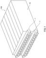
- Fig. 1 is a perspective view of a power storage unit 100 including a pressure-regulating valve 1 for a power storage module according to a first embodiment of the present invention
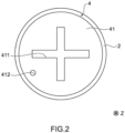
- Fig. 2 is a plan view of the pressure-regulating valve 1 for a power storage module
- Fig. 3 is a sectional view schematically showing the pressure-regulating valve 1 for a power storage module
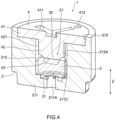
- Fig. 4 is a sectional view of the pressure-regulating valve 1 for a power storage module
- Fig. 5 is a sectional view of a valve body 3 of the pressure-regulating valve 1 for a power storage module
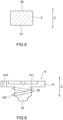
- Fig. 6 is a sectional view of a plug body 4 of the pressure-regulating valve 1 for a power storage module
- Fig. 7 is a sectional view of a case 2 of the pressure-regulating valve 1 for a power storage module.
- the pressure-regulating valve 1 for a power storage module includes a case 2 having a recessed part 21, and a through-hole 211A formed in a bottom portion 211 of the recessed part 21, a valve body 3 positioned in the recessed part 21 and capable of opening and closing the through-hole 211A by elasticity, and a plug body 4 that closes the recessed part 21, and the case 2 and the plug body 4 are attachably and detachably fixed.
- the pressure-regulating valve 1 for a power storage module will be specifically described. Note that since Figs. 2 and 3 are schematic views, there exist some differences from Figs. 4 to 7 on the drawings, but Figs. 2 to 7 show the same embodiment.
- the power storage unit 100 is configured by the pressure-regulating valve 1 for a power storage module and a power storage device (power storage module) 10.
- the pressure-regulating valve 1 for a power storage module is configured to release pressure when internal pressure rises in the power storage device 10.
- the power storage device 10 is, for example, a nickel hydrogen battery, and is provided to supply electric power to a motor in a vehicle such as an electric car, and a hybrid car.
- the case 2 is formed of a synthetic resin, for example, and a plurality of recessed parts 21 are formed.
- Figs. 3 , 4 and 7 illustrate only one of the recessed parts 21, it is assumed that the other recessed parts are similar.
- the recessed part 21 is formed in a recessed shape that is opened upward in Fig. 3 by having the bottom portion 211, a valve body placement portion 212, and a large diameter portion 213.
- a depth direction (up-down direction in Fig. 3 ) of the recessed part 21 is defined as a Z direction
- a side where the recessed part 21 is opened in the Z direction is defined as an opening side
- a side (lower side in Fig. 3 ) where the bottom portion 211 of the recessed part 21 is provided in the Z direction is defined as an introduction side.
- the bottom portion 211 extends along a plane orthogonal to the Z direction, and has the through-hole 211A formed in a center portion, a groove portion 211B communicating with the through-hole 211A, and a bead 211C protruding from a surface on an opening side.
- An opening portion that discharges gas of the power storage device 10 is positioned on the introduction side of the bottom portion 211, and the gas is introduced toward an inside of the recessed part 21 from the introduction side through the through-hole 211A.
- the groove portion 211B is formed to partially enlarge a diameter of the through-hole 211A. Thereby, an area at a time of pressure of the gas introduced into the recessed part 21 from the through-hole 211A acting on the valve body 3 increases.
- the groove portion 211B can be formed in response to a set pressure that opens the valve body 3, and the groove portion may be omitted.
- the bead 211C is formed into an annular shape around an axis along the Z direction and is formed into a triangular shape (blade shape) in section having a vertex on the opening side.
- the bead 211C functions as a valve seat when the valve body 3 contacts the bead 211C.
- the bead 211C can bite into the valve body 3 which is an elastic member, thereby improving surface pressure and ensuring sealing performance.
- the bead 211C is not limited to the one having a triangular shape in section but may have other shapes.
- the valve body placement portion 212 is formed closer to the opening side than the bottom portion 211, and is formed to be able to accommodate the valve body 3.
- a threaded portion 212A is formed on an inner peripheral surface of the cylindrical valve body placement portion 212.
- the threaded portion 212A is a female screw portion. Note that the threaded portion 212A can be formed on at least a portion in which the plug body 4 is provided, the threaded portion 212A may be formed on the entire valve body placement portion 212, or the threaded portion 212A may not be formed in the portion where the valve body 3 is provided.
- the large diameter portion 213 is positioned closer to the opening side (opposite side to the bottom portion 211 with the valve body placement portion 212 therebetween) than the valve body placement portion 212 with an inner peripheral surface formed in a cylindrical shape, and is formed to have a diameter larger than the valve body placement portion 212.
- the valve body 3 is entirely formed of an elastic member and is formed into a circular columnar shape (or a disk shape) with a height direction in the Z direction.
- An outside diameter of the valve body 3 is slightly smaller than the inside diameter of the valve body placement portion 212, so that the valve body 3 can be positioned in the valve body placement portion 212 and the valve body 3 does not incline.
- a bottom surface (surface on the introduction side) 31 of the valve body 3 is a seat surface, and is capable of contacting the bead 211C.
- the plug body 4 is formed of a synthetic resin, for example, and integrally has a disk-shaped flange portion 41, a protrusion portion 42 protruding to the introduction side from the flange portion 41, and a pressing portion 43 provided at a tip end of the protrusion portion 42.
- An outside diameter of the flange portion 41 is larger than the inside diameter of the valve body placement portion 212 and slightly smaller than an inside diameter of the large diameter portion 213, and the flange portion 41 is positioned in the large diameter portion 213.
- a +-shaped groove portion 411 is formed on a top surface (surface on the opening side) of the flange portion 41, and is operable by a Phillips-head screwdriver. Note that a tool for operating the flange portion 41 is not limited to a Phillips-head screwdriver, but a groove or the like in a shape corresponding to the tool can be formed on the top surface.
- a vent hole 412 penetrating in the Z direction is formed in the flange portion 41, and a space in the recessed part 21 and an external space on the opening side are caused to communicate with each other. Thereby, when the internal pressure of the power storage device 10 rises and gas is introduced into the recessed part 21, the gas can be released to the external space.
- the protrusion portion 42 is formed into a circular columnar shape, and a threaded portion 421 is formed on an outer peripheral surface thereof.
- the threaded portion 421 is a male screw portion.
- the threaded portion 421 can be screwed into the threaded portion 212A formed on the recessed part 21. That is to say, the plug body 4 moves to the introduction side by operating the flange portion 41 by a tool and rotating the plug body 4 in one direction around the axis along the Z direction, and moves to the opening side by rotating the plug body in another direction. In this way, the plug body 4 is fixed to the case 2 by screwing.
- the positions where the threaded portions are formed are not limited to the recessed part 21 and the protrusion portion 42, but the threaded portions can be formed at positions corresponding to each other on a case side and a plug body side.
- the pressing portion 43 has a tapering shape in which an outside diameter becomes smaller as progress toward a tip end side (introduction side), and a tip end surface thereof abuts on a top surface (surface on the opening side) 32 of the valve body 3.
- the pressing portion 43 approaches the valve body 3 and abuts on the valve body 3.
- the valve body 3 is pressed, pressed against the bead 211C of the case 2 and compressed.
- the pressure-regulating valve 1 for a power storage module functions as follows. First, when the internal pressure of the power storage device 10 is smaller than a preset reference value, a force to the valve opening side as a result of the internal pressure acting on the valve body 3 is smaller than a force for opening the valve body 3. Accordingly, the valve body 3 keeps a closed state. On the other hand, when the internal pressure of the power storage device 10 reaches the reference value or more, the force to the valve opening side becomes equal to or larger than the force for opening the valve body 3, the valve body 3 deforms and the bottom surface 31 separates from the bead 211C.
- valve body 3 opens, gas passes through the through-hole 211A to flow into the recessed part 21 from the power storage device 10.
- the gas passes through the vent hole 412 of the flange portion 41 and is released to the outside from the inside of the recessed part 21.
- the pressure-regulating valve 1 for a power storage module may have an initial failure such as being unable to obtain desired valve opening characteristics due to malfunction in respective components or poor assembly. At this time, it is possible to replace components, or correct an assembled state by removing the plug body 4 screwed into the case 2. As described above, a plurality of recessed parts are formed in the case 2, and the valve body 3 and the plug body 4 identical or nearly identical to the above description are provided in each of these recessed parts. Accordingly, if an initial failure occurs in some of the valves, the plug bodies 4 can be removed from only those valves as targets.
- the valve body 3 which is an elastic member deteriorates and elasticity may be reduced, or a battery electrolyte may become insufficient. At this time, it is possible to replace the valve body 3, or refill the battery electrolyte by removing the plug body 4.
- the plug body 4 and the case 2 are attachably and detachably fixed, it is possible to remove the plug body 4 from the case 2 in response to an initial failure, deterioration or the like, and it is possible to improve maintainability.
- the case 2 has a plurality of recessed parts 21, and the plug body 4 is provided for each of the plurality of recessed parts 21, it is possible to remove only some of the plug bodies 4, and it is possible to improve maintainability as compared with the configuration in which a common cover is provided for a plurality of recessed parts.
- the common cover is provided for a plurality of recessed parts, it is necessary to replace a whole of the configuration when malfunctions occur to some valves, whereas in the configuration in which the plug body 4 is provided for each of the plurality of recessed parts 21, it is possible to cope with the malfunctions by replacement or the like of components in only the valves where malfunctions occur.
- a pressure-regulating valve 1B for a power storage module according to a second embodiment of the present invention differs from the pressure-regulating valve 1 for a power storage module of the first embodiment in a point that a fitting recessed part 213A and a fitting protruding part 413 are provided instead of the threaded portions 212A and 421, and positions where these portions are provided, as shown in Fig. 8 , and common components are assigned with same reference signs and explanation thereof is omitted.
- the fitting recessed part 213A is formed in a large diameter portion 213 of a case 2, and the fitting protruding part 413 is formed at a flange portion 41 positioned in the large diameter portion 213, of a plug body 4.
- the fitting protruding part 413 and the fitting recessed part 213A fit together (are fitted together) by pressing the plug body 4 in the Z direction, and thereby the case 2 and the plug body 4 are fixed. Further, by inclining the plug body 4 with respect to the case 2 by using a tool, for example, fitting can be released.
- the pressure-regulating valve 1B for a power storage module of the second embodiment like this it is also possible to improve maintainability as in the first embodiment.
- a configuration in which the fitting recessed part is provided on the plug body side, and the fitting protruding part is provided on the case side may be adopted. Further, the positions for forming the fitting recessed part and the fitting protruding part are not limited to this.
- Figs. 9 to 11 are perspective views of a pressure-regulating valve 1C for a power storage module according to a third embodiment of the present invention.
- the pressure-regulating valve 1C for a power storage module according to the third embodiment of the present invention includes a case 5 having a recessed part 51 and a through-hole formed in a bottom portion of the recessed part 51, a valve body 6 positioned in the recessed part 51 and capable of opening and closing the through-hole by elasticity, and a plug body 7 that has a pressing portion 73 pressing the valve body 6 to a valve closing side, and closes the recessed part 51, and the case 5 and the plug body 7 are attachably and detachably fixed.
- the case 5 has a case body 5A in which the recessed part 51 is formed, and a lid portion 5B provided on an opposite side to the bottom portion with respect to the recessed part 51.
- the lid portion 5B is provided to close the recessed part 51.
- An entire surface of the case body 5A and the lid portion 5B can be fixed together, for example, by welding.
- a passing hole 52 through which the plug body 7 is passable is formed in the lid portion 5B.
- the passing hole 52 has a circular portion 521, and three notch portions 522 formed in predetermined positions in a circumferential direction so that a diameter of the circular portion 521 is enlarged.
- the three notch portions 522 are equidistantly disposed in the circumferential direction, for example.
- the recessed part 51 has a circular portion 511 which overlaps the circular portion 521 of the passing hole 52 and in which the valve body 6 is positioned, and three notch portions 512 that are formed in predetermined positions in a circumferential direction so that a diameter of the circular portion 511 is enlarged.
- a dimension in the circumferential direction of the notch portion 512 of the recessed part 51 is formed to be large with respect to the notch portion 522 of the passing hole 52. Thereby, the notch portion 522 of the passing hole 52 is positioned to overlap a part of the notch portion 512 of the recessed part 51.
- the valve body 6 is identical or nearly identical to the valve body 3 of the first embodiment.
- the plug body 7 has a circular columnar base portion 71, three protruding parts 72 formed to protrude to an outer periphery side from an outer peripheral surface of the base portion 71, and the pressing portion 73 protruding from the base portion 71 toward an inside of the recessed part 51 (toward a valve body 6 side).
- the base portion 71 has dimensions capable of passing through the passing hole 52.
- a groove portion 711 is formed on a surface facing an opposite side to the valve body 6, of the base portion 71, as in the first embodiment, and is operable by a tool, and the plug body 7 is rotatable around an axial direction along the Z direction.
- the protruding parts 72 are equidistantly disposed in the circumferential direction identically to the notch portions 522, and each has dimensions capable of passing through the notch portion 522. Furthermore, a circumferential dimension of the protruding part 72 is smaller than a circumferential dimension of the notch portion 512 of the recessed part 51, the protruding part 72 is movable in the circumferential direction in the notch portion 512. In other words, the plug body 7 is rotatable in a state of being accommodated in the recessed part 51.
- the pressing portion 73 is identical or nearly identical to to the pressing portion 43 of the first embodiment.
- the respective three protruding parts 72 are in the positions corresponding to the three notch portions 522, and the plug body 7 can pass through the passing hole 52.
- the protruding part 72 is positioned in the notch portion 512 of the recessed part 51. Subsequently, when the plug body 7 is rotated around the axial direction, the protruding part 72 moves in the notch portion 512, and the protruding part 72 and the notch portion 522 do not overlap in the Z direction.
- the protruding part 72 is incapable of passing through the notch portion 522 of the passing hole 52 (abuts on a portion around the passing hole 52, of the lid portion 5B), and movement toward an outside of the recessed part 51 is restricted. Thereby, the plug body 7 is restricted from falling off, and is fixed to the case 5.
- the present invention is not limited to the mode of the above-described embodiments, but includes other configurations and the like that can achieve the object of the present invention, and modifications and the like as shown below are also included in the present invention.
- the case 2 has the plurality of recessed parts 21, and the plug body 4 is provided for each of the plurality of recessed parts 21, a configuration in which a case has only one recessed part may be adopted. This also applies to the second and third embodiments.
- the present invention is not limited to the pressure-regulating valves for a power storage module according to the embodiments of the present invention described above, but includes all aspects included in the idea and the claims of the present invention. Further, in order to exhibit at least a part of the problem and the effects described above, the respective configurations may be selectively combined as appropriate. For example, the shapes, materials, placements, sizes and the like of the respective components in the embodiments can be changed as appropriate according to a specific use aspect of the present invention.
Landscapes
- Engineering & Computer Science (AREA)
- General Engineering & Computer Science (AREA)
- Chemical & Material Sciences (AREA)
- Chemical Kinetics & Catalysis (AREA)
- Electrochemistry (AREA)
- General Chemical & Material Sciences (AREA)
- Mechanical Engineering (AREA)
- Gas Exhaust Devices For Batteries (AREA)
Abstract
Description
- The present invention relates to a pressure-regulating valve for a power storage module.
- Conventionally, as a power storage module for a battery to be mounted on a vehicle, there has been proposed a power storage module provided with a pressure-regulating valve (for example, see Patent Literature 1). In the power storage module described in
Patent Literature 1, the pressure-regulating valve includes a case member in which a cylindrical portion is formed, a valve body that is an elastic member to be accommodated in the cylindrical portion, and a cover member that closes an opening of the case member. Further, the cover member presses the valve body to press the valve body against the opening end. Thereby, when the pressure in the internal space reaches a set value or more, closing of the opening end by the valve body is released. - Patent Literature 1: International Publication No.
WO 2019/064843 - In the power storage module described in
Patent Literature 1, the cover member is joined to the case member by welding or the like. Therefore, it is not possible to remove the cover member from the case member, and it is not possible to cope with, for example, the case in which the valve body is deteriorated and elasticity is reduced, the case in which desired valve opening characteristics cannot be obtained due to an initial failure, the case in which a battery electrolyte becomes insufficient, and the like, and there is an disadvantage of maintainability being low. - The present invention is made in view of the aforementioned problem, and it is an object of the present invention to provide a pressure-regulating valve for a power storage module capable of improving maintenance.
- In order to attain the above-described object, a pressure-regulating valve for a power storage module according to the present invention includes a case having a recessed part, and a through-hole formed in a bottom portion of the recessed part, a valve body positioned in the recessed part and capable of opening and closing the through-hole by elasticity, and a plug body that closes the recessed part, wherein the case and the plug body are attachably and detachably fixed.
- In the pressure-regulating valve for a power storage module according to one aspect of the present invention, the case and the plug body are attachable and detachable as a result of threaded portions being formed in the case and the plug body respectively.
- In the pressure-regulating valve for a power storage module according to one aspect of the present invention, the plug body and the case are attachable and detachable as a result of a fitting protruding part being provided at one of the plug body and the case, and a fitting recessed part to be fitted on the fitting protruding part being provided at another one.
- In the pressure-regulating valve for a power storage module according to one aspect of the present invention, the case has a case body in which the recessed part is formed, and a lid portion provided on an opposite side to the bottom portion with respect to the recessed part, the plug body is provided rotatably with respect to the case with an insertion direction to the recessed part in an axial direction, and has a protruding part toward an outer periphery side, the lid portion has a passing hole through which the plug body at a predetermined rotation angle can pass, and the plug body is restricted from falling off as a result of rotating after passing through the passing hole, and thereby the protruding part becomes incapable of passing through the passing hole.
- In the pressure-regulating valve for a power storage module according to one aspect of the present invention, the case has a plurality of the recessed parts, and the valve body and the plug body are provided for each of the plurality of recessed parts.
- According to the pressure-regulating valve for a power storage module according to the present invention, it is possible to improve maintainability.
-
- [
Fig. 1] Fig. 1 is a perspective view of a power storage unit including a pressure-regulating valve for a power storage module according to a first embodiment of the present invention. - [
Fig. 2] Fig. 2 is a plan view of the pressure-regulating valve for a power storage module according to the first embodiment of the present invention. - [
Fig. 3] Fig. 3 is a sectional view schematically showing the pressure-regulating valve for a power storage module according to the first embodiment of the present invention. - [
Fig. 4] Fig. 4 is a sectional view of the pressure-regulating valve for a power storage module according to the first embodiment of the present invention. - [
Fig. 5] Fig. 5 is a sectional view of a valve body of the pressure-regulating valve for a power storage module according to the first embodiment of the present invention. - [
Fig. 6] Fig. 6 is a sectional view of a plug body of the pressure-regulating valve for a power storage module according to the first embodiment of the present invention. - [
Fig. 7] Fig. 7 is a sectional view of a case of the pressure-regulating valve for a power storage module according to the first embodiment of the present invention. - [
Fig. 8] Fig. 8 is a sectional view schematically showing a pressure-regulating valve for a power storage module according to a second embodiment of the present invention. - [
Fig. 9] Fig. 9 is an exploded perspective view of a pressure-regulating valve for a power storage module according to a third embodiment of the present invention. - [
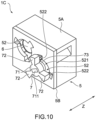
Fig. 10] Fig. 10 is an exploded perspective view of the pressure-regulating valve for a power storage module according to the third embodiment of the present invention. - [
Fig. 11] Fig. 11 is a perspective view of the pressure-regulating valve for a power storage module according to the third embodiment of the present invention. - Hereinafter, embodiments of the present invention will be described with reference to the drawings.
-
Fig. 1 is a perspective view of apower storage unit 100 including a pressure-regulatingvalve 1 for a power storage module according to a first embodiment of the present invention,Fig. 2 is a plan view of the pressure-regulatingvalve 1 for a power storage module,Fig. 3 is a sectional view schematically showing the pressure-regulatingvalve 1 for a power storage module,Fig. 4 is a sectional view of the pressure-regulatingvalve 1 for a power storage module,Fig. 5 is a sectional view of avalve body 3 of the pressure-regulatingvalve 1 for a power storage module,Fig. 6 is a sectional view of aplug body 4 of the pressure-regulatingvalve 1 for a power storage module, andFig. 7 is a sectional view of acase 2 of the pressure-regulatingvalve 1 for a power storage module. - As shown in
Figs. 1 to 7 , the pressure-regulatingvalve 1 for a power storage module according to the first embodiment of the present invention includes acase 2 having arecessed part 21, and a through-hole 211A formed in abottom portion 211 of therecessed part 21, avalve body 3 positioned in therecessed part 21 and capable of opening and closing the through-hole 211A by elasticity, and aplug body 4 that closes therecessed part 21, and thecase 2 and theplug body 4 are attachably and detachably fixed. Hereinafter, the pressure-regulatingvalve 1 for a power storage module will be specifically described. Note that sinceFigs. 2 and3 are schematic views, there exist some differences fromFigs. 4 to 7 on the drawings, butFigs. 2 to 7 show the same embodiment. - As shown in
Fig. 1 , thepower storage unit 100 is configured by the pressure-regulatingvalve 1 for a power storage module and a power storage device (power storage module) 10. The pressure-regulatingvalve 1 for a power storage module is configured to release pressure when internal pressure rises in thepower storage device 10. Thepower storage device 10 is, for example, a nickel hydrogen battery, and is provided to supply electric power to a motor in a vehicle such as an electric car, and a hybrid car. - The
case 2 is formed of a synthetic resin, for example, and a plurality of recessedparts 21 are formed. AlthoughFigs. 3 ,4 and7 illustrate only one of therecessed parts 21, it is assumed that the other recessed parts are similar. Therecessed part 21 is formed in a recessed shape that is opened upward inFig. 3 by having thebottom portion 211, a valvebody placement portion 212, and alarge diameter portion 213. Hereinafter, for convenience of explanation, a depth direction (up-down direction inFig. 3 ) of therecessed part 21 is defined as a Z direction, a side where therecessed part 21 is opened in the Z direction is defined as an opening side, and a side (lower side inFig. 3 ) where thebottom portion 211 of therecessed part 21 is provided in the Z direction is defined as an introduction side. - The
bottom portion 211 extends along a plane orthogonal to the Z direction, and has the through-hole 211A formed in a center portion, agroove portion 211B communicating with the through-hole 211A, and abead 211C protruding from a surface on an opening side. An opening portion that discharges gas of thepower storage device 10 is positioned on the introduction side of thebottom portion 211, and the gas is introduced toward an inside of therecessed part 21 from the introduction side through the through-hole 211A. - The
groove portion 211B is formed to partially enlarge a diameter of the through-hole 211A. Thereby, an area at a time of pressure of the gas introduced into therecessed part 21 from the through-hole 211A acting on thevalve body 3 increases. Thegroove portion 211B can be formed in response to a set pressure that opens thevalve body 3, and the groove portion may be omitted. - The
bead 211C is formed into an annular shape around an axis along the Z direction and is formed into a triangular shape (blade shape) in section having a vertex on the opening side. Thebead 211C functions as a valve seat when thevalve body 3 contacts thebead 211C. When thebead 211C is formed into a blade shape, thebead 211C can bite into thevalve body 3 which is an elastic member, thereby improving surface pressure and ensuring sealing performance. Note that thebead 211C is not limited to the one having a triangular shape in section but may have other shapes. - The valve
body placement portion 212 is formed closer to the opening side than thebottom portion 211, and is formed to be able to accommodate thevalve body 3. A threadedportion 212A is formed on an inner peripheral surface of the cylindrical valvebody placement portion 212. The threadedportion 212A is a female screw portion. Note that the threadedportion 212A can be formed on at least a portion in which theplug body 4 is provided, the threadedportion 212A may be formed on the entire valvebody placement portion 212, or the threadedportion 212A may not be formed in the portion where thevalve body 3 is provided. - The
large diameter portion 213 is positioned closer to the opening side (opposite side to thebottom portion 211 with the valvebody placement portion 212 therebetween) than the valvebody placement portion 212 with an inner peripheral surface formed in a cylindrical shape, and is formed to have a diameter larger than the valvebody placement portion 212. - The
valve body 3 is entirely formed of an elastic member and is formed into a circular columnar shape (or a disk shape) with a height direction in the Z direction. An outside diameter of thevalve body 3 is slightly smaller than the inside diameter of the valvebody placement portion 212, so that thevalve body 3 can be positioned in the valvebody placement portion 212 and thevalve body 3 does not incline. A bottom surface (surface on the introduction side) 31 of thevalve body 3 is a seat surface, and is capable of contacting thebead 211C. - The
plug body 4 is formed of a synthetic resin, for example, and integrally has a disk-shapedflange portion 41, aprotrusion portion 42 protruding to the introduction side from theflange portion 41, and apressing portion 43 provided at a tip end of theprotrusion portion 42. - An outside diameter of the
flange portion 41 is larger than the inside diameter of the valvebody placement portion 212 and slightly smaller than an inside diameter of thelarge diameter portion 213, and theflange portion 41 is positioned in thelarge diameter portion 213. A +-shapedgroove portion 411 is formed on a top surface (surface on the opening side) of theflange portion 41, and is operable by a Phillips-head screwdriver. Note that a tool for operating theflange portion 41 is not limited to a Phillips-head screwdriver, but a groove or the like in a shape corresponding to the tool can be formed on the top surface. - A
vent hole 412 penetrating in the Z direction is formed in theflange portion 41, and a space in the recessedpart 21 and an external space on the opening side are caused to communicate with each other. Thereby, when the internal pressure of thepower storage device 10 rises and gas is introduced into the recessedpart 21, the gas can be released to the external space. - The
protrusion portion 42 is formed into a circular columnar shape, and a threadedportion 421 is formed on an outer peripheral surface thereof. The threadedportion 421 is a male screw portion. The threadedportion 421 can be screwed into the threadedportion 212A formed on the recessedpart 21. That is to say, theplug body 4 moves to the introduction side by operating theflange portion 41 by a tool and rotating theplug body 4 in one direction around the axis along the Z direction, and moves to the opening side by rotating the plug body in another direction. In this way, theplug body 4 is fixed to thecase 2 by screwing. Note that the positions where the threaded portions are formed are not limited to the recessedpart 21 and theprotrusion portion 42, but the threaded portions can be formed at positions corresponding to each other on a case side and a plug body side. - The
pressing portion 43 has a tapering shape in which an outside diameter becomes smaller as progress toward a tip end side (introduction side), and a tip end surface thereof abuts on a top surface (surface on the opening side) 32 of thevalve body 3. When theplug body 4 is rotated in the one direction as described above in a state in which thevalve body 3 is accommodated in the recessedpart 21, thepressing portion 43 approaches thevalve body 3 and abuts on thevalve body 3. When rotation is further continued in this state, thevalve body 3 is pressed, pressed against thebead 211C of thecase 2 and compressed. As a result of an undersurface of theflange portion 41 abutting on a top surface of thelarge diameter portion 213, movement of theplug body 4 to the introduction side is restricted, and a pressing amount is controlled. - When the pressure-regulating
valve 1 for a power storage module as described above is provided in thepower storage device 10, and internal pressure of thepower storage device 10 changes, the pressure-regulatingvalve 1 for a power storage module functions as follows. First, when the internal pressure of thepower storage device 10 is smaller than a preset reference value, a force to the valve opening side as a result of the internal pressure acting on thevalve body 3 is smaller than a force for opening thevalve body 3. Accordingly, thevalve body 3 keeps a closed state. On the other hand, when the internal pressure of thepower storage device 10 reaches the reference value or more, the force to the valve opening side becomes equal to or larger than the force for opening thevalve body 3, thevalve body 3 deforms and thebottom surface 31 separates from thebead 211C. In other words, thevalve body 3 opens, gas passes through the through-hole 211A to flow into the recessedpart 21 from thepower storage device 10. The gas passes through thevent hole 412 of theflange portion 41 and is released to the outside from the inside of the recessedpart 21. - The pressure-regulating
valve 1 for a power storage module may have an initial failure such as being unable to obtain desired valve opening characteristics due to malfunction in respective components or poor assembly. At this time, it is possible to replace components, or correct an assembled state by removing theplug body 4 screwed into thecase 2. As described above, a plurality of recessed parts are formed in thecase 2, and thevalve body 3 and theplug body 4 identical or nearly identical to the above description are provided in each of these recessed parts. Accordingly, if an initial failure occurs in some of the valves, theplug bodies 4 can be removed from only those valves as targets. - By using the
power storage device 10 provided with the pressure-regulatingvalve 1 for a power storage module, various deteriorations and the like may occur in respective parts. For example, thevalve body 3 which is an elastic member deteriorates and elasticity may be reduced, or a battery electrolyte may become insufficient. At this time, it is possible to replace thevalve body 3, or refill the battery electrolyte by removing theplug body 4. - In this way, according to the pressure-regulating
valve 1 for a power storage module according to the embodiment of the present invention, since theplug body 4 and thecase 2 are attachably and detachably fixed, it is possible to remove theplug body 4 from thecase 2 in response to an initial failure, deterioration or the like, and it is possible to improve maintainability. - Further, since the
case 2 has a plurality of recessedparts 21, and theplug body 4 is provided for each of the plurality of recessedparts 21, it is possible to remove only some of theplug bodies 4, and it is possible to improve maintainability as compared with the configuration in which a common cover is provided for a plurality of recessed parts. In particular, in the configuration in which the common cover is provided for a plurality of recessed parts, it is necessary to replace a whole of the configuration when malfunctions occur to some valves, whereas in the configuration in which theplug body 4 is provided for each of the plurality of recessedparts 21, it is possible to cope with the malfunctions by replacement or the like of components in only the valves where malfunctions occur. - A pressure-regulating
valve 1B for a power storage module according to a second embodiment of the present invention differs from the pressure-regulatingvalve 1 for a power storage module of the first embodiment in a point that a fitting recessedpart 213A and a fitting protrudingpart 413 are provided instead of the threadedportions Fig. 8 , and common components are assigned with same reference signs and explanation thereof is omitted. - The fitting recessed
part 213A is formed in alarge diameter portion 213 of acase 2, and the fitting protrudingpart 413 is formed at aflange portion 41 positioned in thelarge diameter portion 213, of aplug body 4. For example, thefitting protruding part 413 and the fitting recessedpart 213A fit together (are fitted together) by pressing theplug body 4 in the Z direction, and thereby thecase 2 and theplug body 4 are fixed. Further, by inclining theplug body 4 with respect to thecase 2 by using a tool, for example, fitting can be released. - In the pressure-regulating
valve 1B for a power storage module of the second embodiment like this, it is also possible to improve maintainability as in the first embodiment. Note that a configuration in which the fitting recessed part is provided on the plug body side, and the fitting protruding part is provided on the case side may be adopted. Further, the positions for forming the fitting recessed part and the fitting protruding part are not limited to this. -
Figs. 9 to 11 are perspective views of a pressure-regulatingvalve 1C for a power storage module according to a third embodiment of the present invention. The pressure-regulatingvalve 1C for a power storage module according to the third embodiment of the present invention includes acase 5 having a recessedpart 51 and a through-hole formed in a bottom portion of the recessedpart 51, avalve body 6 positioned in the recessedpart 51 and capable of opening and closing the through-hole by elasticity, and aplug body 7 that has apressing portion 73 pressing thevalve body 6 to a valve closing side, and closes the recessedpart 51, and thecase 5 and theplug body 7 are attachably and detachably fixed. - The
case 5 has acase body 5A in which the recessedpart 51 is formed, and alid portion 5B provided on an opposite side to the bottom portion with respect to the recessedpart 51. In other words, thelid portion 5B is provided to close the recessedpart 51. An entire surface of thecase body 5A and thelid portion 5B can be fixed together, for example, by welding. - A passing
hole 52 through which theplug body 7 is passable is formed in thelid portion 5B. The passinghole 52 has acircular portion 521, and threenotch portions 522 formed in predetermined positions in a circumferential direction so that a diameter of thecircular portion 521 is enlarged. The threenotch portions 522 are equidistantly disposed in the circumferential direction, for example. - The recessed
part 51 has acircular portion 511 which overlaps thecircular portion 521 of the passinghole 52 and in which thevalve body 6 is positioned, and threenotch portions 512 that are formed in predetermined positions in a circumferential direction so that a diameter of thecircular portion 511 is enlarged. A dimension in the circumferential direction of thenotch portion 512 of the recessedpart 51 is formed to be large with respect to thenotch portion 522 of the passinghole 52. Thereby, thenotch portion 522 of the passinghole 52 is positioned to overlap a part of thenotch portion 512 of the recessedpart 51. - The
valve body 6 is identical or nearly identical to thevalve body 3 of the first embodiment. - The
plug body 7 has a circularcolumnar base portion 71, three protrudingparts 72 formed to protrude to an outer periphery side from an outer peripheral surface of thebase portion 71, and thepressing portion 73 protruding from thebase portion 71 toward an inside of the recessed part 51 (toward avalve body 6 side). Thebase portion 71 has dimensions capable of passing through the passinghole 52. Agroove portion 711 is formed on a surface facing an opposite side to thevalve body 6, of thebase portion 71, as in the first embodiment, and is operable by a tool, and theplug body 7 is rotatable around an axial direction along the Z direction. - The protruding
parts 72 are equidistantly disposed in the circumferential direction identically to thenotch portions 522, and each has dimensions capable of passing through thenotch portion 522. Furthermore, a circumferential dimension of the protrudingpart 72 is smaller than a circumferential dimension of thenotch portion 512 of the recessedpart 51, the protrudingpart 72 is movable in the circumferential direction in thenotch portion 512. In other words, theplug body 7 is rotatable in a state of being accommodated in the recessedpart 51. Thepressing portion 73 is identical or nearly identical to to thepressing portion 43 of the first embodiment. - Only when the
rotatable plug body 7 is moved to a predetermined rotation angle, the respective three protrudingparts 72 are in the positions corresponding to the threenotch portions 522, and theplug body 7 can pass through the passinghole 52. When theplug body 7 passes through the passinghole 52, the protrudingpart 72 is positioned in thenotch portion 512 of the recessedpart 51. Subsequently, when theplug body 7 is rotated around the axial direction, the protrudingpart 72 moves in thenotch portion 512, and the protrudingpart 72 and thenotch portion 522 do not overlap in the Z direction. In other words, the protrudingpart 72 is incapable of passing through thenotch portion 522 of the passing hole 52 (abuts on a portion around the passinghole 52, of thelid portion 5B), and movement toward an outside of the recessedpart 51 is restricted. Thereby, theplug body 7 is restricted from falling off, and is fixed to thecase 5. - On the other hand, when the
plug body 7 is rotated in an opposite direction to the above, in the state in which theplug body 7 is fixed to thecase 5, the protrudingparts 72 move to positions where they overlap thenotch portions 522, and theplug body 7 is brought into the state in which it can pass through the passinghole 52 again. In other words, it is possible to remove theplug body 7 from thecase 5. - In the pressure-regulating
valve 1C for a power storage module of the third embodiment like this, it is also possible to improve maintainability as in the first embodiment. - Note that the present invention is not limited to the mode of the above-described embodiments, but includes other configurations and the like that can achieve the object of the present invention, and modifications and the like as shown below are also included in the present invention. For example, in the first embodiment of the present invention described above, although the
case 2 has the plurality of recessedparts 21, and theplug body 4 is provided for each of the plurality of recessedparts 21, a configuration in which a case has only one recessed part may be adopted. This also applies to the second and third embodiments. - Although the embodiments of the present invention are described thus far, the present invention is not limited to the pressure-regulating valves for a power storage module according to the embodiments of the present invention described above, but includes all aspects included in the idea and the claims of the present invention. Further, in order to exhibit at least a part of the problem and the effects described above, the respective configurations may be selectively combined as appropriate. For example, the shapes, materials, placements, sizes and the like of the respective components in the embodiments can be changed as appropriate according to a specific use aspect of the present invention.
-
- 1, 1B, 1C pressure-regulating valve for power storage module
- 2, 5 case
- 21, 51 recessed part
- 211 bottom portion
- 211A through-hole
- 211B groove portion
- 211C bead
- 212 valve body placement portion
- 212A threaded portion
- 213 large diameter portion
- 213A fitting recessed part
- 3, 6 valve body
- 31 bottom surface
- 32 top surface
- 4, 7 plug body
- 41 flange portion
- 411, 711 groove portion
- 412 vent hole
- 413 fitting protruding part
- 42 protrusion portion
- 421 threaded portion
- 43, 73 pressing portion
- 5A case body
- 5B lid portion
- 52 passing hole
- 511 circular portion
- 512 notch portion
- 521 circular portion
- 522 notch portion
- 71 base portion
- 72 protruding part
- 10 power storage device (power storage module)
- 100 power storage unit
Claims (5)
- A pressure-regulating valve for a power storage module, comprising:a case having a recessed part, and a through-hole formed in a bottom portion of the recessed part;a valve body positioned in the recessed part and capable of opening and closing the through-hole by elasticity; anda plug body that closes the recessed part, whereinthe case and the plug body are attachably and detachably fixed.
- The pressure-regulating valve for a power storage module according to claim 1, wherein the case and the plug body are attachable and detachable as a result of threaded portions being formed in the case and the plug body respectively.
- The pressure-regulating valve for a power storage module according to claim 1, wherein the plug body and the case are attachable and detachable as a result of a fitting protruding part being provided at one of the plug body and the case, and a fitting recessed part to be fitted on the fitting protruding part being provided at another one.
- The pressure-regulating valve for a power storage module according to claim 1, wherein
the case has a case body in which the recessed part is formed, and a lid portion provided on an opposite side to the bottom portion with respect to the recessed part,
the plug body is provided rotatably with respect to the case with an insertion direction to the recessed part in an axial direction, and has a protruding part toward an outer periphery side,
the lid portion has a passing hole through which the plug body at a predetermined rotation angle can pass, and
the plug body is restricted from falling off as a result of rotating after passing through the passing hole, and thereby the protruding part becomes incapable of passing through the passing hole. - The pressure-regulating valve for a power storage module according to any one of claims 1 to 4, wherein
the case has a plurality of the recessed parts, and
the valve body and the plug body are provided for each of the plurality of recessed parts.
Applications Claiming Priority (2)
| Application Number | Priority Date | Filing Date | Title |
|---|---|---|---|
| JP2021151484 | 2021-09-16 | ||
| PCT/JP2022/030050 WO2023042570A1 (en) | 2021-09-16 | 2022-08-05 | Pressure-regulating valve for power storage module |
Publications (2)
| Publication Number | Publication Date |
|---|---|
| EP4404359A1 true EP4404359A1 (en) | 2024-07-24 |
| EP4404359A4 EP4404359A4 (en) | 2025-09-03 |
Family
ID=85602742
Family Applications (1)
| Application Number | Title | Priority Date | Filing Date |
|---|---|---|---|
| EP22869718.1A Pending EP4404359A4 (en) | 2021-09-16 | 2022-08-05 | PRESSURE CONTROL VALVE FOR POWER STORAGE MODULE |
Country Status (6)
| Country | Link |
|---|---|
| US (1) | US20240405350A1 (en) |
| EP (1) | EP4404359A4 (en) |
| JP (1) | JP7703035B2 (en) |
| KR (1) | KR20240046561A (en) |
| CN (1) | CN117941146A (en) |
| WO (1) | WO2023042570A1 (en) |
Family Cites Families (14)
| Publication number | Priority date | Publication date | Assignee | Title |
|---|---|---|---|---|
| JPS4832261Y1 (en) * | 1970-03-31 | 1973-10-02 | ||
| JPS5024987Y1 (en) * | 1970-03-31 | 1975-07-28 | ||
| GB2085217B (en) * | 1980-09-25 | 1984-02-15 | Chloride Group Ltd | Vent for electric storage battery |
| DE202005003835U1 (en) * | 2005-03-10 | 2005-05-04 | Abertax Research And Development Ltd. | Gas venting valve for battery cells has closure element provided as elastic seal element fitted around outside of valve body in alignment with radial vent channel |
| JP5081486B2 (en) | 2007-01-12 | 2012-11-28 | 株式会社Nttファシリティーズ | Battery container and stopper |
| JP2012156489A (en) * | 2011-01-06 | 2012-08-16 | Mitsubishi Electric Corp | Storage element |
| JP2014099266A (en) * | 2012-11-13 | 2014-05-29 | Toyota Industries Corp | Power storage device and sealing method of power storage device |
| CN103928646B (en) * | 2014-04-25 | 2016-01-13 | 长兴金程橡胶有限公司 | Adjustable die mould storage battery safety valve |
| JP2018133374A (en) * | 2017-02-13 | 2018-08-23 | 株式会社東芝 | Pressure relief mechanism |
| WO2018199238A1 (en) * | 2017-04-28 | 2018-11-01 | 日東電工株式会社 | Gas-permeable unit |
| US11355785B2 (en) | 2017-09-26 | 2022-06-07 | Kabushiki Kaisha Toyota Jidoshokki | Power storage module and method for manufacturing power storage module |
| JP7234908B2 (en) * | 2019-11-26 | 2023-03-08 | 株式会社豊田自動織機 | Pressure regulating valve structure and power storage module |
| CN211957783U (en) | 2020-04-01 | 2020-11-17 | 陆家铭 | Multi-modular vehicle-mounted storage battery valve seat |
| CN212161870U (en) * | 2020-05-14 | 2020-12-15 | 宁德时代新能源科技股份有限公司 | End cap assemblies, housing assemblies, secondary batteries, battery packs, devices using batteries, and liquid injection devices |
-
2022
- 2022-08-05 KR KR1020247008499A patent/KR20240046561A/en active Pending
- 2022-08-05 CN CN202280062670.9A patent/CN117941146A/en active Pending
- 2022-08-05 EP EP22869718.1A patent/EP4404359A4/en active Pending
- 2022-08-05 JP JP2023548160A patent/JP7703035B2/en active Active
- 2022-08-05 WO PCT/JP2022/030050 patent/WO2023042570A1/en not_active Ceased
- 2022-08-05 US US18/691,342 patent/US20240405350A1/en active Pending
Also Published As
| Publication number | Publication date |
|---|---|
| WO2023042570A1 (en) | 2023-03-23 |
| US20240405350A1 (en) | 2024-12-05 |
| CN117941146A (en) | 2024-04-26 |
| KR20240046561A (en) | 2024-04-09 |
| JP7703035B2 (en) | 2025-07-04 |
| JPWO2023042570A1 (en) | 2023-03-23 |
| EP4404359A4 (en) | 2025-09-03 |
Similar Documents
| Publication | Publication Date | Title |
|---|---|---|
| EP4109656B1 (en) | End cover assembly, battery cell, battery and electric device | |
| JP5973136B2 (en) | Rotary valve | |
| US9092035B2 (en) | Internal pilot type pressure regulator | |
| JP2006144841A (en) | Fixing structure and manual valve of valve device | |
| US12313174B2 (en) | Pressure-relief valve for reducing pressure arising in a cell-like cavity, such as a battery cell | |
| US20100270300A1 (en) | Structure for fuel filling section of fuel tank | |
| CN103867893A (en) | Pressure reducing valve | |
| US10428968B2 (en) | Valve core | |
| KR102069391B1 (en) | Flow rate adjusting device | |
| US20240405350A1 (en) | Pressure-regulating valve for power storage module | |
| JP2015148309A (en) | triple eccentric butterfly valve | |
| CN201037564Y (en) | Battery safety valve | |
| JP7667269B2 (en) | Pressure release valve for power storage device | |
| CN101473484A (en) | Fuel cell | |
| JP7407335B2 (en) | pressure regulating valve | |
| EP2249069A1 (en) | Relief valve | |
| JP4898865B2 (en) | Relief valve | |
| CN218468290U (en) | Plug valve for asphalt tank truck | |
| WO2017149700A1 (en) | Solenoid device and electromagnetic valve | |
| CN217926102U (en) | Fuel metering valve | |
| US20250180123A1 (en) | Valve for a refrigeration application | |
| CN118149123A (en) | Eccentric hemisphere valve | |
| JP2025056918A (en) | Pressure Regulating Valve | |
| WO2026034433A1 (en) | Pressure relief valve | |
| JP2012226984A (en) | Sealed battery and safety valve |
Legal Events
| Date | Code | Title | Description |
|---|---|---|---|
| STAA | Information on the status of an ep patent application or granted ep patent |
Free format text: STATUS: THE INTERNATIONAL PUBLICATION HAS BEEN MADE |
|
| PUAI | Public reference made under article 153(3) epc to a published international application that has entered the european phase |
Free format text: ORIGINAL CODE: 0009012 |
|
| STAA | Information on the status of an ep patent application or granted ep patent |
Free format text: STATUS: REQUEST FOR EXAMINATION WAS MADE |
|
| 17P | Request for examination filed |
Effective date: 20240325 |
|
| AK | Designated contracting states |
Kind code of ref document: A1 Designated state(s): AL AT BE BG CH CY CZ DE DK EE ES FI FR GB GR HR HU IE IS IT LI LT LU LV MC MK MT NL NO PL PT RO RS SE SI SK SM TR |
|
| DAV | Request for validation of the european patent (deleted) | ||
| DAX | Request for extension of the european patent (deleted) | ||
| A4 | Supplementary search report drawn up and despatched |
Effective date: 20250801 |
|
| RIC1 | Information provided on ipc code assigned before grant |
Ipc: H01M 50/308 20210101AFI20250728BHEP Ipc: H01M 50/317 20210101ALI20250728BHEP Ipc: H01M 50/325 20210101ALI20250728BHEP Ipc: F16K 17/02 20060101ALI20250728BHEP Ipc: F16K 27/00 20060101ALI20250728BHEP Ipc: F16K 27/02 20060101ALI20250728BHEP |