EP4404326A1 - Battery, electric device, and manufacturing method for battery - Google Patents
Battery, electric device, and manufacturing method for battery Download PDFInfo
- Publication number
- EP4404326A1 EP4404326A1 EP21957784.8A EP21957784A EP4404326A1 EP 4404326 A1 EP4404326 A1 EP 4404326A1 EP 21957784 A EP21957784 A EP 21957784A EP 4404326 A1 EP4404326 A1 EP 4404326A1
- Authority
- EP
- European Patent Office
- Prior art keywords
- battery
- branch
- probe
- coolant
- bottom plate
- Prior art date
- Legal status (The legal status is an assumption and is not a legal conclusion. Google has not performed a legal analysis and makes no representation as to the accuracy of the status listed.)
- Pending
Links
- 238000004519 manufacturing process Methods 0.000 title claims abstract description 9
- 238000001514 detection method Methods 0.000 claims abstract description 132
- 239000002826 coolant Substances 0.000 claims abstract description 112
- 238000001816 cooling Methods 0.000 claims abstract description 43
- 239000007788 liquid Substances 0.000 claims abstract description 43
- 239000000523 sample Substances 0.000 claims description 113
- 125000006850 spacer group Chemical group 0.000 claims description 39
- 239000003990 capacitor Substances 0.000 claims description 30
- 238000012545 processing Methods 0.000 claims description 7
- 238000010586 diagram Methods 0.000 description 10
- 230000002452 interceptive effect Effects 0.000 description 8
- 238000005516 engineering process Methods 0.000 description 5
- 238000009413 insulation Methods 0.000 description 5
- 230000008901 benefit Effects 0.000 description 4
- 238000011161 development Methods 0.000 description 4
- 230000035945 sensitivity Effects 0.000 description 4
- HBBGRARXTFLTSG-UHFFFAOYSA-N Lithium ion Chemical compound [Li+] HBBGRARXTFLTSG-UHFFFAOYSA-N 0.000 description 3
- 229910001416 lithium ion Inorganic materials 0.000 description 3
- 238000002791 soaking Methods 0.000 description 3
- XLYOFNOQVPJJNP-UHFFFAOYSA-N water Substances O XLYOFNOQVPJJNP-UHFFFAOYSA-N 0.000 description 3
- VNWKTOKETHGBQD-UHFFFAOYSA-N methane Chemical compound C VNWKTOKETHGBQD-UHFFFAOYSA-N 0.000 description 2
- 238000011160 research Methods 0.000 description 2
- 229910001415 sodium ion Inorganic materials 0.000 description 2
- 230000001960 triggered effect Effects 0.000 description 2
- DGAQECJNVWCQMB-PUAWFVPOSA-M Ilexoside XXIX Chemical compound C[C@@H]1CC[C@@]2(CC[C@@]3(C(=CC[C@H]4[C@]3(CC[C@@H]5[C@@]4(CC[C@@H](C5(C)C)OS(=O)(=O)[O-])C)C)[C@@H]2[C@]1(C)O)C)C(=O)O[C@H]6[C@@H]([C@H]([C@@H]([C@H](O6)CO)O)O)O.[Na+] DGAQECJNVWCQMB-PUAWFVPOSA-M 0.000 description 1
- JLVVSXFLKOJNIY-UHFFFAOYSA-N Magnesium ion Chemical compound [Mg+2] JLVVSXFLKOJNIY-UHFFFAOYSA-N 0.000 description 1
- FKNQFGJONOIPTF-UHFFFAOYSA-N Sodium cation Chemical compound [Na+] FKNQFGJONOIPTF-UHFFFAOYSA-N 0.000 description 1
- JDZCKJOXGCMJGS-UHFFFAOYSA-N [Li].[S] Chemical compound [Li].[S] JDZCKJOXGCMJGS-UHFFFAOYSA-N 0.000 description 1
- 238000005520 cutting process Methods 0.000 description 1
- 238000004134 energy conservation Methods 0.000 description 1
- 238000004146 energy storage Methods 0.000 description 1
- 230000007613 environmental effect Effects 0.000 description 1
- 239000002803 fossil fuel Substances 0.000 description 1
- 239000011810 insulating material Substances 0.000 description 1
- 229910001425 magnesium ion Inorganic materials 0.000 description 1
- 229910052751 metal Inorganic materials 0.000 description 1
- 239000002184 metal Substances 0.000 description 1
- 238000000034 method Methods 0.000 description 1
- 238000012986 modification Methods 0.000 description 1
- 230000004048 modification Effects 0.000 description 1
- 239000003345 natural gas Substances 0.000 description 1
- 238000004806 packaging method and process Methods 0.000 description 1
- 230000008092 positive effect Effects 0.000 description 1
- 239000011734 sodium Substances 0.000 description 1
- 238000010998 test method Methods 0.000 description 1
Images




Classifications
-
- G—PHYSICS
- G01—MEASURING; TESTING
- G01M—TESTING STATIC OR DYNAMIC BALANCE OF MACHINES OR STRUCTURES; TESTING OF STRUCTURES OR APPARATUS, NOT OTHERWISE PROVIDED FOR
- G01M3/00—Investigating fluid-tightness of structures
- G01M3/02—Investigating fluid-tightness of structures by using fluid or vacuum
- G01M3/04—Investigating fluid-tightness of structures by using fluid or vacuum by detecting the presence of fluid at the leakage point
- G01M3/16—Investigating fluid-tightness of structures by using fluid or vacuum by detecting the presence of fluid at the leakage point using electric detection means
-
- H—ELECTRICITY
- H01—ELECTRIC ELEMENTS
- H01M—PROCESSES OR MEANS, e.g. BATTERIES, FOR THE DIRECT CONVERSION OF CHEMICAL ENERGY INTO ELECTRICAL ENERGY
- H01M10/00—Secondary cells; Manufacture thereof
- H01M10/42—Methods or arrangements for servicing or maintenance of secondary cells or secondary half-cells
-
- H—ELECTRICITY
- H01—ELECTRIC ELEMENTS
- H01M—PROCESSES OR MEANS, e.g. BATTERIES, FOR THE DIRECT CONVERSION OF CHEMICAL ENERGY INTO ELECTRICAL ENERGY
- H01M10/00—Secondary cells; Manufacture thereof
- H01M10/42—Methods or arrangements for servicing or maintenance of secondary cells or secondary half-cells
- H01M10/4228—Leak testing of cells or batteries
-
- H—ELECTRICITY
- H01—ELECTRIC ELEMENTS
- H01M—PROCESSES OR MEANS, e.g. BATTERIES, FOR THE DIRECT CONVERSION OF CHEMICAL ENERGY INTO ELECTRICAL ENERGY
- H01M10/00—Secondary cells; Manufacture thereof
- H01M10/42—Methods or arrangements for servicing or maintenance of secondary cells or secondary half-cells
- H01M10/425—Structural combination with electronic components, e.g. electronic circuits integrated to the outside of the casing
-
- H—ELECTRICITY
- H01—ELECTRIC ELEMENTS
- H01M—PROCESSES OR MEANS, e.g. BATTERIES, FOR THE DIRECT CONVERSION OF CHEMICAL ENERGY INTO ELECTRICAL ENERGY
- H01M10/00—Secondary cells; Manufacture thereof
- H01M10/42—Methods or arrangements for servicing or maintenance of secondary cells or secondary half-cells
- H01M10/48—Accumulators combined with arrangements for measuring, testing or indicating the condition of cells, e.g. the level or density of the electrolyte
-
- H—ELECTRICITY
- H01—ELECTRIC ELEMENTS
- H01M—PROCESSES OR MEANS, e.g. BATTERIES, FOR THE DIRECT CONVERSION OF CHEMICAL ENERGY INTO ELECTRICAL ENERGY
- H01M10/00—Secondary cells; Manufacture thereof
- H01M10/60—Heating or cooling; Temperature control
- H01M10/61—Types of temperature control
- H01M10/613—Cooling or keeping cold
-
- H—ELECTRICITY
- H01—ELECTRIC ELEMENTS
- H01M—PROCESSES OR MEANS, e.g. BATTERIES, FOR THE DIRECT CONVERSION OF CHEMICAL ENERGY INTO ELECTRICAL ENERGY
- H01M10/00—Secondary cells; Manufacture thereof
- H01M10/60—Heating or cooling; Temperature control
- H01M10/61—Types of temperature control
- H01M10/615—Heating or keeping warm
-
- H—ELECTRICITY
- H01—ELECTRIC ELEMENTS
- H01M—PROCESSES OR MEANS, e.g. BATTERIES, FOR THE DIRECT CONVERSION OF CHEMICAL ENERGY INTO ELECTRICAL ENERGY
- H01M10/00—Secondary cells; Manufacture thereof
- H01M10/60—Heating or cooling; Temperature control
- H01M10/62—Heating or cooling; Temperature control specially adapted for specific applications
- H01M10/625—Vehicles
-
- H—ELECTRICITY
- H01—ELECTRIC ELEMENTS
- H01M—PROCESSES OR MEANS, e.g. BATTERIES, FOR THE DIRECT CONVERSION OF CHEMICAL ENERGY INTO ELECTRICAL ENERGY
- H01M10/00—Secondary cells; Manufacture thereof
- H01M10/60—Heating or cooling; Temperature control
- H01M10/65—Means for temperature control structurally associated with the cells
- H01M10/655—Solid structures for heat exchange or heat conduction
- H01M10/6556—Solid parts with flow channel passages or pipes for heat exchange
-
- H—ELECTRICITY
- H01—ELECTRIC ELEMENTS
- H01M—PROCESSES OR MEANS, e.g. BATTERIES, FOR THE DIRECT CONVERSION OF CHEMICAL ENERGY INTO ELECTRICAL ENERGY
- H01M10/00—Secondary cells; Manufacture thereof
- H01M10/60—Heating or cooling; Temperature control
- H01M10/65—Means for temperature control structurally associated with the cells
- H01M10/656—Means for temperature control structurally associated with the cells characterised by the type of heat-exchange fluid
- H01M10/6567—Liquids
-
- H—ELECTRICITY
- H01—ELECTRIC ELEMENTS
- H01M—PROCESSES OR MEANS, e.g. BATTERIES, FOR THE DIRECT CONVERSION OF CHEMICAL ENERGY INTO ELECTRICAL ENERGY
- H01M10/00—Secondary cells; Manufacture thereof
- H01M10/60—Heating or cooling; Temperature control
- H01M10/65—Means for temperature control structurally associated with the cells
- H01M10/656—Means for temperature control structurally associated with the cells characterised by the type of heat-exchange fluid
- H01M10/6567—Liquids
- H01M10/6568—Liquids characterised by flow circuits, e.g. loops, located externally to the cells or cell casings
-
- H—ELECTRICITY
- H01—ELECTRIC ELEMENTS
- H01M—PROCESSES OR MEANS, e.g. BATTERIES, FOR THE DIRECT CONVERSION OF CHEMICAL ENERGY INTO ELECTRICAL ENERGY
- H01M50/00—Constructional details or processes of manufacture of the non-active parts of electrochemical cells other than fuel cells, e.g. hybrid cells
- H01M50/20—Mountings; Secondary casings or frames; Racks, modules or packs; Suspension devices; Shock absorbers; Transport or carrying devices; Holders
- H01M50/289—Mountings; Secondary casings or frames; Racks, modules or packs; Suspension devices; Shock absorbers; Transport or carrying devices; Holders characterised by spacing elements or positioning means within frames, racks or packs
- H01M50/291—Mountings; Secondary casings or frames; Racks, modules or packs; Suspension devices; Shock absorbers; Transport or carrying devices; Holders characterised by spacing elements or positioning means within frames, racks or packs characterised by their shape
-
- H—ELECTRICITY
- H01—ELECTRIC ELEMENTS
- H01M—PROCESSES OR MEANS, e.g. BATTERIES, FOR THE DIRECT CONVERSION OF CHEMICAL ENERGY INTO ELECTRICAL ENERGY
- H01M50/00—Constructional details or processes of manufacture of the non-active parts of electrochemical cells other than fuel cells, e.g. hybrid cells
- H01M50/20—Mountings; Secondary casings or frames; Racks, modules or packs; Suspension devices; Shock absorbers; Transport or carrying devices; Holders
- H01M50/298—Mountings; Secondary casings or frames; Racks, modules or packs; Suspension devices; Shock absorbers; Transport or carrying devices; Holders characterised by the wiring of battery packs
-
- H—ELECTRICITY
- H01—ELECTRIC ELEMENTS
- H01M—PROCESSES OR MEANS, e.g. BATTERIES, FOR THE DIRECT CONVERSION OF CHEMICAL ENERGY INTO ELECTRICAL ENERGY
- H01M50/00—Constructional details or processes of manufacture of the non-active parts of electrochemical cells other than fuel cells, e.g. hybrid cells
- H01M50/50—Current conducting connections for cells or batteries
- H01M50/569—Constructional details of current conducting connections for detecting conditions inside cells or batteries, e.g. details of voltage sensing terminals
-
- H—ELECTRICITY
- H01—ELECTRIC ELEMENTS
- H01M—PROCESSES OR MEANS, e.g. BATTERIES, FOR THE DIRECT CONVERSION OF CHEMICAL ENERGY INTO ELECTRICAL ENERGY
- H01M10/00—Secondary cells; Manufacture thereof
- H01M10/42—Methods or arrangements for servicing or maintenance of secondary cells or secondary half-cells
- H01M10/425—Structural combination with electronic components, e.g. electronic circuits integrated to the outside of the casing
- H01M2010/4271—Battery management systems including electronic circuits, e.g. control of current or voltage to keep battery in healthy state, cell balancing
-
- H—ELECTRICITY
- H01—ELECTRIC ELEMENTS
- H01M—PROCESSES OR MEANS, e.g. BATTERIES, FOR THE DIRECT CONVERSION OF CHEMICAL ENERGY INTO ELECTRICAL ENERGY
- H01M2220/00—Batteries for particular applications
- H01M2220/20—Batteries in motive systems, e.g. vehicle, ship, plane
-
- Y—GENERAL TAGGING OF NEW TECHNOLOGICAL DEVELOPMENTS; GENERAL TAGGING OF CROSS-SECTIONAL TECHNOLOGIES SPANNING OVER SEVERAL SECTIONS OF THE IPC; TECHNICAL SUBJECTS COVERED BY FORMER USPC CROSS-REFERENCE ART COLLECTIONS [XRACs] AND DIGESTS
- Y02—TECHNOLOGIES OR APPLICATIONS FOR MITIGATION OR ADAPTATION AGAINST CLIMATE CHANGE
- Y02E—REDUCTION OF GREENHOUSE GAS [GHG] EMISSIONS, RELATED TO ENERGY GENERATION, TRANSMISSION OR DISTRIBUTION
- Y02E60/00—Enabling technologies; Technologies with a potential or indirect contribution to GHG emissions mitigation
- Y02E60/10—Energy storage using batteries
Definitions
- This application relates to the field of battery technologies, and in particular, to a battery, an electric device, and a battery manufacturing method.
- a coolant inside the battery for cooling battery cells may escape, affecting the safety performance of the battery.
- This application provides a battery, an electric device, and a battery manufacturing method, so as to quickly detect coolant leaks and improve the safety performance of the battery.
- this application provides a battery including:
- the detection position of the detection part included in the detection apparatus is set between the battery cell and the bottom plate.
- the detection part can detect the coolant before the coolant comes into contact with the battery cell. This prevents the battery cell from being soaked in the coolant and protects electrical components of the battery cell against short circuit or damage, effectively protecting the battery cell and increasing the service life of the battery cell. This can also prevent battery safety accidents, improving the safety performance of the battery.
- the detection position of the detection part is 1 mm to 5 mm above the bottom plate. This range of distance can facilitate the arrangement of the detection apparatus, and can also ensure that a coolant leak is detected before the coolant comes into contact with the battery cell, effectively protecting the battery cell.
- the detection part is disposed on the bottom plate.
- the benefit of such arrangement is that the coolant can be detected in the first place, and a coolant leak can be detected as quickly as possible, preventing the coolant from soaking components near the bottom plate.
- the battery further includes a spacer plate disposed between the battery cell and the bottom plate, where the spacer plate has a recess with an opening facing the bottom plate, the detection apparatus includes a terminal disposed in the recess, and the terminal is connected to the detection part.
- the terminal With the spacer plate and the recess on the spacer plate, the terminal can be hidden in the recess, so that the problem of interfering with the assembly caused by a terminal exposed on a surface of the spacer plate can be avoided. This facilitates the assembly of the spacer plate.
- the detection part includes a probe connected to the terminal.
- the recess is located on an edge of the spacer plate and an open portion is formed at a side facing the edge, and the probe extends from the terminal in a direction away from the open portion.
- the recess is provided so that the terminal can be pushed into the recess through the open portion on the edge of the spacer plate.
- the open portion helps position the terminal and guide the mounting of the terminal, greatly facilitating the mounting of the detection apparatus.
- the probe extends from the terminal in the direction away from the open portion, so that an end portion of the probe can be placed at a side of the terminal away from the open portion. In this way, the probe is effectively protected by the side wall of the recess and prevented from reaching out of the recess or spacer plate to rub against or collide with other components inside the battery. Such rub or collision will compromise the safety of the probe and shorten the service life of the probe.
- the battery further includes a first electrical connection wire, a second electrical connection wire, and a battery management system, where the detection part includes a first probe and a second probe, the first electrical connection wire connects the first probe and the battery management system, and the second electrical connection wire connects the second probe and the battery management system.
- the first electrical connection wire, the second electrical connection wire, and the battery management system are provided, so that the first probe and the second probe connected via the coolant can be connected to the battery management system through the first electrical connection wire and the second electrical connection wire. Then, the battery management system can determine whether the coolant is detected based on the change of connectivity between the two probes.
- the first probe, the first electrical connection wire, and the battery management system are connected to form a first branch, the first branch is provided with a first voltage terminal, and the first voltage terminal is configured to provide the first branch with a voltage of a first preset value; and the second probe, the second electrical connection wire, and the battery management system are connected to form a second branch, the second branch is provided with a second voltage terminal, the second voltage terminal is configured to provide the second branch with a voltage of a second preset value, and the battery management system is configured to determine whether the detection apparatus detects the coolant leaked from the liquid cooling system, by detecting a voltage difference between the first branch and the second branch.
- the first voltage terminal is provided on the first branch to provide the voltage of the first preset value for the first branch
- the second voltage terminal is provided on the second branch to provide the voltage of the second preset value for the second branch, so that whether a coolant leak occurs can be determined by detecting a difference between the voltages of the two branches.
- the battery further includes a first resistor, a first capacitor, a second resistor, and a second capacitor, where the first resistor is connected to the first branch, one end of the first capacitor is connected to the first branch and another end of the first capacitor is grounded, the second resistor is connected to the second branch, and one end of the second capacitor is connected to the second branch and another end of the second capacitor is grounded.
- the first resistor and the first capacitor form a first filter to filter out interfering signals of the first branch.
- the second resistor and the second capacitor form a second filter to filter out interfering signals of the second branch.
- the battery management system includes a processing module, and the processing module is configured to: when it is detected that an absolute value of the voltage difference between the first branch and the second branch is greater than or equal to an absolute value of a difference between U 1 and U 2 , determine that the detection apparatus detects no coolant leaked from the liquid cooling system, where U 1 is an absolute value of a difference between the first preset value and the second preset value, and U 2 is 0-1 V; and when it is detected that the absolute value of the voltage difference between the first branch and the second branch is smaller than or equal to U 3 , determine that the detection apparatus detects the coolant leaked from the liquid cooling system, where U 3 is 0-1 V and U 3 is smaller than the absolute value of the difference between U 1 and U 2 .
- the processing module can determine whether a coolant leak occurs based on the absolute value of the detected voltage difference.
- the determining criteria set in this embodiment of this application take into account the difference between the actual voltage difference and the theoretical voltage difference due to factors such as energy-consuming components or thermal consumption on the circuit, thereby effectively reducing the false alarm rate and increasing the detection accuracy.
- a distance between the first probe and the second probe is 5 mm to 10 mm. An excessively great distance between the two probes may affect the sensitivity of their connection. An excessively small distance between the two probes may lead to a mistaken connection.
- the first probe and the second probe are both cylindrical, and the first probe has a diameter of 0.5 mm to 3 mm and/or the second probe has a diameter of 0.5 mm to 3 mm.
- the diameters of the probes set within that range, the detection requirements can be met and the volume of the detection apparatus can also be effectively controlled. This avoids the case that the detection apparatus is too large to be mounted easily, helping reduce costs.
- this application provides an electric device including the foregoing battery, where the battery is configured to supply electric energy to the electric device.
- the electric device provided in the embodiment of this application can quickly and accurately detect whether a coolant leak occurs or whether the leakage reaches a preset amount. This effectively protects the battery, improving the use safety of the electric device.
- this application provides a battery manufacturing method including:
- the battery manufactured according to the battery manufacturing method embodiment of this application can quickly and accurately detect whether a coolant leak occurs or whether the leakage reaches a preset amount. This effectively protects the battery cell, improving the safety performance of the battery.
- first means being vertical with an allowable range of error other than being strictly vertical.
- Parallel is not parallel in the strict sense but within an allowable range of error.
- the term "and/or" is only an associative relationship for describing associated objects, indicating that three relationships may be present.
- a and/or B may indicate the following three cases: presence of only A, presence of both A and B, and presence of only B.
- the character "/" in this specification generally indicates an "or" relationship between contextually associated objects.
- a plurality of means at least two unless otherwise specifically stated.
- a plurality of groups means more than two groups and "a plurality of pieces” means more than two pieces unless otherwise specifically stated.
- the technical terms “installment”, “link”, “connection”, and “fix” should be understood in their general senses.
- the terms may be a fixed connection, a detachable connection, or an integrated connection; or may be a mechanical connection or an electrical connection; or may be a direct connection, or an indirect connection through an intermediate medium; or may be an internal connection between two components or an interactive relationship between two components.
- install may be a fixed connection, a detachable connection, or an integrated connection; or may be a mechanical connection or an electrical connection; or may be a direct connection, or an indirect connection through an intermediate medium; or may be an internal connection between two components or an interactive relationship between two components.
- Traction batteries have been not only used in energy storage power supply systems such as hydroelectric power plants, thermal power plants, wind power plants, and solar power plants, but also widely used in many other fields including electric transportation tools such as electric bicycles, electric motorcycles, and electric vehicles, military equipment, and aerospace. With continuous expansion of application fields of traction batteries, market demands for the traction batteries are also expanding.
- a thermal management system is provided in the battery for adjusting the operating temperature of the battery.
- the thermal management system uses a liquid cooling system for temperature control of the battery.
- the liquid cooling system includes a liquid cooling plate and a water pipe, where the water pipe is disposed on the liquid cooling plate and is filled with a coolant. The coolant flows in the water pipe and the liquid cooling plate to cool the battery.
- a coolant leak may cause short circuit or damage of electrical components inside the battery, which shortens the service life of the battery and may also cause safety accidents and endanger personal safety.
- the inventors have improved the structure of the battery, and the improved battery can detect a coolant leak in the first place, ensuring the use safety of the battery.
- the coolant can be quickly detected, avoiding the case that an alarm is triggered after the electrical components inside the battery have been soaked in the coolant. This greatly improves the detection sensitivity, thereby effectively improving the safety performance of the battery.
- An embodiment of this application provides an electric device using a battery as a power source, where the battery is configured to supply electric energy to the electric device.
- the electric device may be a mobile phone, a portable device, a notebook computer, an electric bicycle, an electric vehicle, a steamship, a spacecraft, an electric toy, an electric tool, or the like.
- the spacecraft includes an airplane, a rocket, a space shuttle, a spaceship, or the like.
- the electric toy includes a fixed or mobile electric toy, such as a game console, an electric vehicle toy, an electric ship toy, and an electric airplane toy.
- the electric tool includes an electric metal cutting tool, an electric grinding tool, an electric assembly tool, and an electric railway-specific tool, such as an electric drill, an electric grinder, an electric wrench, an electric screwdriver, an electric hammer, an electric impact drill, a concrete vibrator, and an electric planer.
- an electric drill such as an electric drill, an electric grinder, an electric wrench, an electric screwdriver, an electric hammer, an electric impact drill, a concrete vibrator, and an electric planer.
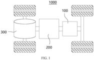
- the electric device is a vehicle 1000 according to an embodiment of this application is used for description in the following embodiments.
- FIG. 1 is a schematic structural diagram of a vehicle 1000 used as the electric device according to some embodiments of this application.
- the vehicle 1000 may be an oil-fueled vehicle, a gas-powered vehicle, or a new energy vehicle.
- the new energy vehicle may be a battery electric vehicle, a hybrid electric vehicle, an extended-range electric vehicle, or the like.
- the vehicle 1000 is provided with a battery 100 inside, and the battery 100 may be disposed at the bottom, front, or rear of the vehicle 1000.
- the battery 100 may be configured to supply power to the vehicle 1000.
- the battery 100 may be used as an operational power supply for the vehicle 1000.
- the vehicle 1000 may further include a controller 200 and a motor 300, where the battery 100 is configured to supply electric energy to the motor 300 and other components of the vehicle, and the controller 200 is configured to control the operation of the motor 300, for example, to satisfy power needs of start, navigation, and driving of the vehicle 1000.
- the battery 100 is configured to supply electric energy to the motor 300 and other components of the vehicle
- the controller 200 is configured to control the operation of the motor 300, for example, to satisfy power needs of start, navigation, and driving of the vehicle 1000.
- the battery 100 can be used as not only the operational power source for the vehicle 1000 but also a driving power source for the vehicle 1000, replacing or partially replacing fossil fuel or natural gas to provide driving traction for the vehicle 1000.
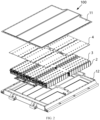
- FIG. 2 is an exploded view of a battery 100 according to some embodiments of this application.
- the battery 100 includes a housing 1 and a battery cell 2, where the battery cell 2 is accommodated in the housing 1.
- the housing 1 is configured to provide an accommodating space for the battery cell 2, and the housing 1 may be of various structures.
- the housing 1 may include a bottom plate 11 and a housing body 12.
- the bottom plate 11 is a plate structure
- the housing body 12 is a hollow structure with one side open.
- the bottom plate 11 covers the open side of the housing body 12, and the bottom plate 11 and the housing body 12 jointly define a space for accommodating the battery cells 2.
- the bottom plate 11 may alternatively be a non-plate structure.
- the bottom plate 11 and the housing body 12 may each be a hollow structure with one side open, and the open side of the bottom plate 11 covers the open side of the housing body 12.
- the housing 1 formed by the bottom plate 11 and the housing body 12 may be in various shapes such as a cylinder and a cuboid.
- FIG. 3 is a schematic structural diagram of an assembled battery 100. During use, the battery 100 is turned upside down as compared to the state shown in FIG. 3 and then placed. In this case, the bottom plate 11 is at the bottom of the housing body 12.
- a plurality of battery cells 2 may be provided, and the plurality of battery cells 2 may be connected in series, parallel, or series-parallel, where a series-parallel connection refers to a combination of series and parallel connections among the plurality of battery cells 2.
- the plurality of battery cells 2 may be directly connected in series, parallel, or series-parallel, and then an entirety of the plurality of battery cells 2 is accommodated in the housing 1.
- the battery 100 may be obtained by accommodating in the housing 1 a plurality of battery modules connected in series, parallel, or series-parallel, where each of the battery modules is formed by connecting a plurality of battery cells 2 in series, parallel, or series-parallel.
- the battery 100 may further include other structures.
- the battery 100 may further include a busbar configured to implement electrical connection between the plurality of battery cells 2.
- the battery cell 2 may include a lithium-ion secondary battery, a lithium-ion primary battery, a lithium-sulfur battery, a sodium/lithium-ion battery, a sodium-ion battery, a magnesium-ion battery, and the like, which is not limited in this embodiment of this disclosure.
- the battery cell may be cylindrical, flat, or cuboid, or of other shapes, which is not limited in this embodiment of this disclosure either.
- the battery cell is usually categorized into three types depending on the packaging: a cylinder battery cell, a prismatic battery cell, and a pouch battery cell, which is not limited in this embodiment of this disclosure.
- the battery cell 2 is the smallest unit forming a battery. Various options may be available for the structure of the battery cell 2, and details will not be described in this application regarding the specific structure of the battery cell 2.
- FIG. 4 is a schematic structural diagram of the battery without the bottom plate 11 according to the embodiment illustrated in FIG. 3
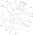
- FIG. 5 is an enlarged view of part A marked in FIG. 4 .
- This application provides a battery 100, and the battery 100 includes a housing 1, a battery cell 2, a liquid cooling system 3, and a detection apparatus 5.
- the housing 1 has a bottom plate 11, the battery cell 2 is disposed inside the housing 1, the liquid cooling system 3 is configured to cool the battery cell 2 by using a coolant, and the detection apparatus 5 is configured to detect coolant leaked from the liquid cooling system 3, where the detection apparatus 5 includes a detection part with a detection position set between the battery cell 2 and the bottom plate 11, so that the detection apparatus 5 can detect the leaked coolant before the leaked coolant comes into contact with the battery cell 2.
- the detection position of the detection part included in the detection apparatus 5 is set between the battery cell 2 and the bottom plate 11.
- the detection part can detect the coolant before the coolant comes into contact with the battery cell 2. This prevents the battery cell 2 from being soaked in the coolant and protects electrical components of the battery cell 2 against short circuit or damage, effectively protecting the battery cell 2 and increasing the service life of the battery cell 2. This can also prevent battery safety accidents, improving the safety performance of the battery.
- the detection position of the detection part is a position where the detection part can detect the coolant.
- the detection part detects the coolant and determines that a coolant leak occurs.
- a coolant leak is detected through insulation checking.
- the detection position of the detection part included in the detection apparatus 5 is set between the battery cell 2 and the bottom plate 11, so that a coolant leak can be detected before the coolant comes into contact with the battery cell 2, effectively protecting the battery cell 2.
- the battery provided in this embodiment of this application has a higher sensitivity in detecting coolant leaks. This can prevent safety accidents as early as possible, and improves the use safety of the battery.
- the bottom plate 11 is at the bottom of the housing 1. During a coolant leak, the liquid level of the coolant will gradually rise from the bottom plate 11. With the detection position of the detection part set between the battery cell 2 and the bottom plate 11, the coolant can be detected in the first place.
- the detection position of the detection part is above the bottom plate 11, and a distance between the detection position of the detection part and the bottom plate 11 is 1 mm to 5 mm, for example, 1 mm, 2 mm, 3 mm, 4 mm, or 5 mm.
- This range of distance can facilitate the arrangement of the detection apparatus 5, and can also ensure that a coolant leak is detected before the coolant comes into contact with the battery cell 2, effectively protecting the battery cell 2.
- the detection part is disposed on the bottom plate 11.
- the benefit of such arrangement is that the coolant can be detected in the first place, and a coolant leak can be detected quickly. Once the coolant is present on the bottom plate 11, the coolant leak can be detected, preventing the coolant from soaking components near the bottom plate 11.
- the battery further includes a spacer plate 4 disposed between the battery cell 2 and the bottom plate 11, where the spacer plate 4 has a recess 41 with an opening facing the bottom plate 11, the detection apparatus 5 includes a terminal 51 disposed in the recess 41, and the terminal 51 is connected to the detection part.
- the terminal 51 can be hidden in the recess 41, so that the problem of interfering with the assembly caused by the terminal 51 exposed on a surface of the spacer plate 4 can be avoided. This facilitates the assembly of the spacer plate 4.
- the liquid cooling system 3 is disposed between the spacer plate 4 and the battery cell 2.
- the spacer plate 4 may also serve as a supporting plate for the liquid cooling system 3, and a liquid transport tube in the liquid cooling system 3 can run through a through hole on the spacer plate 4.
- the spacer plate 4 may also serve as a mounting plate for other components, for example, a sensor for detecting the pressure on the bottom of the battery cell 2.
- the detection apparatus 5 is mounted on the spacer plate 4 with a corresponding function, so that the detection apparatus 5 can be mounted using the existing structure, without the need of special mounting parts for the detection apparatus 5. This can reduce the number of parts of the battery, simplifying the internal structure and reducing costs.
- the detection part includes a probe connected to the terminal 51.
- the recess 41 is located on an edge of the spacer plate 4 and an open portion is formed at a side facing the edge, and the probe extends from the terminal 51 in a direction away from the open portion.
- the recess 41 is disposed on an edge of the spacer plate 4 and an open portion is formed at a side of the recess 41 facing the edge, so that the terminal 51 can be pushed into the recess 41 through the open portion on the edge of the spacer plate 4.
- the open portion helps position the terminal 51 and guide the mounting of the terminal 51, greatly facilitating the mounting of the detection apparatus 5.
- the probe extends from the terminal 51 in the direction away from the open portion, so that an end portion of the probe can be placed at a side of the terminal 51 away from the open portion.
- the probe is effectively protected by the side wall of the recess 41 and is prevented from reaching out of the recess 41 or spacer plate 4 to rub against or collide with other components inside the battery. Such rub or collision will compromise the safety of the probe and shorten the service life of the probe.
- the probe comes into contact with the coolant first at the detection position of the detection part.
- a position, on the outer surface of the probe, close to the bottom plate 11 is the detection position of the detection part, and the coolant being in contact with the position can be detected.
- the battery further includes a first electrical connection wire 54, a second electrical connection wire 55, and a battery management system, where the detection part includes a first probe 52 and a second probe 53, the first electrical connection wire 54 connects the first probe 52 and the battery management system, and the second electrical connection wire 55 connects the second probe 53 and the battery management system.
- the first probe 52 and the second probe 53 extend in parallel directions.
- the first probe 52 and the second probe 53 are disconnected before the coolant is detected.
- the first probe 52 and the second probe 53 are electrically connected via the coolant, and are electrically connected to the battery management system through the first electrical connection wire 54 and the second electrical connection wire 55 respectively.
- the battery management system can determine whether the coolant is detected based on the change of connectivity between the two probes.
- the first probe 52, the first electrical connection wire 54, and the battery management system are connected to form a first branch 91, the first branch 91 is provided with a first voltage terminal 92, and the first voltage terminal 92 is configured to provide the first branch 91 with a voltage of a first preset value; and the second probe 53, the second electrical connection wire 55, and the battery management system are connected to form a second branch 93, the second branch 93 is provided with a second voltage terminal 94, the second voltage terminal 94 is configured to provide the second branch 93 with a voltage of a second preset value, and the battery management system is configured to determine whether the detection apparatus 5 detects the coolant leaked from the liquid cooling system 3, by detecting a voltage difference between the first branch 91 and the second branch 93. In these embodiments, the battery management system determines whether the two probes are electrically connected based on the voltage difference between the two branches, and then determines whether the coolant is detected.
- the battery further includes a first resistor 95, a first capacitor 96, a second resistor 97, and a second capacitor 98, where the first resistor 95 is connected to the first branch 91, one end of the first capacitor 96 is connected to the first branch 91 and another end of the first capacitor 96 is grounded, the second resistor 97 is connected to the second branch 93, and one end of the second capacitor 98 is connected to the second branch 93 and another end of the second capacitor 98 is grounded.
- the first resistor 95 and the first capacitor 96 form a first filter to filter out interfering signals of the first branch 91.
- the second resistor 97 and the second capacitor 98 form a second filter to filter out interfering signals of the second branch 93.
- the battery management system includes a processing module, and the processing module is configured to: when it is detected that an absolute value of the voltage difference between the first branch 91 and the second branch 93 is greater than or equal to an absolute value of a difference between U 1 and U 2 , determine that the detection apparatus 5 detects no coolant leaked from the liquid cooling system 3, where U 1 is an absolute value of a difference between the first preset value and the second preset value, and U 2 is 0-1 V; and when it is detected that the absolute value of the voltage difference between the first branch 91 and the second branch 93 is smaller than or equal to U 3 , determine that the detection apparatus 5 detects the coolant leaked from the liquid cooling system 3, where U 3 is 0-1 V and U 3 is smaller than the absolute value of the difference between U 1 and U 2 .
- the first branch 91 and the second branch 93 are not connected, and the two branches are disconnected.
- the two probes are electrically connected when in contact with the coolant because the coolant is conductive, so that the first branch 91 and the second branch 93 are connected.
- the absolute value of the voltage difference between the first branch 91 and the second branch 93 will change before and after the connection. Therefore, whether the detection apparatus 5 detects the coolant can be determined by checking the absolute value of the voltage difference between the two branches.
- a voltage value of the first branch 91 is the first preset value
- a voltage value of the second branch 93 is the second preset value.
- the absolute value of the voltage difference between the first branch 91 and the second branch 93 should be the absolute value U 1 of the difference between the first preset value and the second preset value.
- the actual absolute value of the voltage difference between the first branch 91 and the second branch 93 may be slightly smaller than U 1 .
- a difference between the absolute value of the actual voltage difference between the first branch 91 and the second branch 93 and the absolute value of the theoretical voltage difference is smaller than U 2 , for example, controlled between 0 V and 1 V U 2 may be 0 V, 0.2 V, 0.4 V, 0.5 V, 0.6 V, 0.8 V, 1 V, or the like.
- the value of U 2 may be set flexibly based on the actual situation. Setting U 2 can avoid the case of mistakenly determining that the detection apparatus 5 detects the coolant when the absolute value of the actual voltage difference between the first branch 91 and the second branch 93 is slightly smaller than U 1 due to factors such as energy-consuming components or thermal consumption on the circuit. This effectively improves the detection accuracy.
- the absolute value of the voltage difference between the first branch 91 and the second branch 93 should theoretically be 0.
- the absolute value of the actual voltage difference between the first branch 91 and the second branch 93 may be slightly greater than 0, for example, U 3 , where U 3 is 0-1 V U 3 may be 0 V, 0.2 V, 0.4 V, 0.5 V, 0.6 V, 0.8 V, 1 V, or the like.
- the value of U 3 may be set flexibly based on the actual situation.
- a distance d1 between the first probe 52 and the second probe 53 is 5 mm to 10 mm, for example, 5 mm, 6 mm, 7 mm, 8 mm, 9 mm or 10 mm.
- An excessively great distance between the two probes may affect the sensitivity of their connection.
- An excessively small distance between the two probes may lead to a mistaken connection.
- the first probe 52 and the second probe 53 are both cylindrical, and the first probe 52 has a diameter d3 of 0.5 mm to 3 mm, for example, 0.5 mm, 1 mm, 2 mm, 3 mm, 4 mm, or 5 mm.
- the second probe 53 has a diameter of 0.5 mm to 3 mm, for example, 0.5 mm, 1 mm, 2 mm, 3 mm, 4 mm, or 5 mm.
- This application further provides an electric device including the foregoing battery, where the battery is configured to supply electric energy to the electric device.
- This application further provides a battery manufacturing method including:
- the electric device and the battery manufacturing method also have the positive effects of the foregoing battery embodiments. Details are not described herein again.
- a battery 100 includes a housing 1, a battery cell 2, a liquid cooling system 3, and a spacer plate 4.
- the housing 1 includes a bottom plate 11 and a housing body 12. An opening is provided at the bottom of the housing body 12, and an accommodating space is provided inside the housing body 12 to accommodate a plurality of battery cells 2.
- the liquid cooling system 3 and the spacer plate 4 are also disposed inside the housing body 12.
- the liquid cooling system 3 is disposed at the bottom of the battery cells 2, and the spacer plate 4 is disposed at the bottom of the liquid cooling system 3.
- the bottom plate 11 covers the opening side of the housing body 12 to enclose the battery cells 2, the liquid cooling system 3, and the spacer plate 4 inside the housing 1.
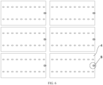
- multiple rows of battery cells 2 are disposed inside the housing 1, and the multiple rows of battery cells 2 are arranged in different regions.
- One spacer plate 4 is disposed in the region where each battery cell 2 is located, and a detection apparatus 5 is mounted on a side edge of the spacer plate 4.
- one side edge of the spacer plate 4 is provided with a protruding portion protruding toward the battery cell 2, and the protruding portion has a recess 41 with an opening facing a direction away from the battery cell 2 or facing the bottom plate 11.
- the detection apparatus 5 is disposed in the recess 41.
- the detection apparatus 5 includes a terminal 51, a first probe 52, a second probe 53, a first electrical connection wire 54, and a second electrical connection wire 55.
- the first probe 52 is connected to the first electrical connection wire 54 through the terminal 51
- the second probe 53 is connected to the second electrical connection wire 55 through the terminal 51.
- the terminal 51 is an electrical connection part, and the terminal 51 has a shell made of an insulating material.
- the terminal 51 is in a square shape. In other embodiments, the terminal 51 may alternatively be in shapes such as rectangle or triangle.
- An open portion is formed at a side of the recess 41 facing the edge of the spacer plate 4.
- the first probe 52 and the second probe 53 are connected to a side of the terminal 51 far away from the open portion, so that the first probe 52 and the second probe 53 can be protected by the side wall of the recess 41. This prevents the first probe 52 and the second probe 53 from interfering or colliding with other components, helping increase the service life of the probes.
- the first electrical connection wire 54 and the second electrical connection wire 55 are connected to a side of the terminal 51 close to the open portion, so that the first electrical connection wire 54 and the second electrical connection wire 55 extend out of the recess 41 and are connected to a battery management system.
- the battery 100 further includes a mounting plate 6.
- the mounting plate 6 is disposed in the recess 41, and the detection apparatus 5 is mounted on the mounting plate 6.
- the shape and size of the mounting plate 6 can match the shape and size of the recess 41, so that the mounting plate 6 placed in the recess 41 will not waggle in the recess 41. This can improve the stability of the detection apparatus 5.
- FIG. 5 is a bottom view.
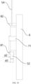
- the detection apparatus 5 is located below the mounting plate 6, and the detection apparatus 5 is closer to the bottom plate 11 than the mounting plate 6. Furthermore, in the embodiment illustrated in FIG. 5 , after the detection apparatus 5 is mounted, a clearance 61 is present between the mounting plate 6 and the bottom of the recess 41.
- the clearance 61 allows the mounting plate 6 to be put into the recess 41 more easily.
- the clearance 61 can also prevent the mounting plate 6 from rubbing against the bottom of the recess 41, effectively protecting the mounting plate 6 and the spacer plate 4.
- the bottom of the recess 41 refers to a surface of the recess 41 opposite its opening.
- the battery 100 further includes a connector, and the terminal 51 is fixed to the mounting plate 6 by using the connector.
- the connector includes a first hook 71 and a second hook 72.
- the first hook 71 and the second hook 72 are disposed on the mounting plate 6 and clamped onto the terminal 51.
- the first hook 71 and the second hook 72 are mounted on one side of the mounting plate 6 close to the bottom plate 11.
- a convex portion is provided at one end of the first hook 71 and one end of the second hook 72 away from the mounting plate 6.
- the convex portions are close to each other.
- the convex portions have inclined surfaces, allowing the terminal 51 to be put into a space defined by the first hook 71 and the second hook 72.
- the convex portions can restrain the terminal 51 after the terminal 51 is put into the space defined by the first hook 71 and the second hook 72, so as to fix the terminal 51.
- the first hook 71 and the second hook 72 are arranged on two sides of the terminal 51 to restrict the terminal 51 to move in a first direction, where the first direction is a direction in which the first hook 71 and the second hook 72 are connected.
- end surfaces of the ends of the first hook 71 and the second hook 72 away from the mounting plate 6 each include a plane, and a distance between the planes and the mounting plate 6 is greater than the distance between the terminal 51 and the mounting plate 6. Therefore, during use of the battery, the planes are in contact with the bottom plate 11, and a preset distance is present between the terminal 51 and the bottom plate 11.
- One end of the first probe 52 and one end of the second probe 53 are connected inside the terminal 51, and a distance between the first probe 52 and the second probe 53 and the mounting plate 6 is also smaller than the distance between the end planes of the first hook 71 and the second hook 72 and the mounting plate 6.
- a distance d2 between an outer surface of the first probe 52 and the end plane of the first hook 71 is 1 mm to 5 mm.
- a distance between an outer surface of the second probe 53 and the end plane of the second hook 72 may also be 1 mm to 5 mm. Such distance can enable the first probe 52 and the second probe 53 to quickly detect the leaked coolant, and also prevent the coolant from soaking the battery cell 2 and other electrical components.
- the battery 100 further includes a positioning piece disposed on the mounting plate 6, where the positioning piece is used to limit the position of the terminal 51 relative to the mounting plate 6, so as to avoid contact between the detection part and the side wall of the recess 41.
- the positioning piece includes a first positioning piece 81 and a second positioning piece 82.
- the first positioning piece 81 and the second positioning piece 82 are arranged on two sides of the terminal 51 to prevent the terminal 51 from moving in a second direction relative to the mounting plate 6, where the second direction is a direction in which the first positioning piece 81 and the second positioning piece 82 are connected.
- the second direction and the first direction are two directions that are not parallel to each other. In the embodiments illustrated in FIG. 5 , and FIG. 7 to FIG. 9 , the first direction is perpendicular to the second direction.
- the first positioning piece 81 and the second positioning piece are similar to the first hook 71 and the second hook 72 in terms of structure, but different from the first hook 71 and the second hook 72, the first positioning piece 81 and the second positioning piece 82 do not have the convex portions.
- End surfaces of the ends of the first positioning piece 81 and the second positioning piece 82 away from the mounting plate 6 also each include a plane, and the planes are in contact with the bottom plate 11.
- the end surfaces of the first positioning piece 81, the second positioning piece 82, the first hook 71, and the second hook 72 are coplanar, so as to ensure the stability of the detection apparatus 5.
- structures of the first positioning piece 81 and the second positioning piece 82 may be the same as or different from those of the first hook 71 and the second hook 72.
- the distance d1 between the first probe 52 and the second probe 53 is 5 mm to 10 mm.
- the diameter d3 of the first probe 52 is 0.5 mm to 3 mm, and the diameter of the second probe 53 may also be 0.5 mm to 3 mm.
- the first branch 91 is connected to a first voltage terminal 92.
- the first voltage terminal 92 supplies a voltage of 5 V to the first branch 91.
- the second branch 93 is connected to a second voltage terminal 94.
- the second voltage terminal 94 is grounded, that is, the second voltage terminal 94 supplies a voltage of 0 V to the second branch 93.
- a third resistor 90 is connected between the first branch 91 and the first voltage terminal 92, and a fourth resistor 99 is connected between the second branch 93 and the second voltage terminal 94.
- a first resistor 95 and a first capacitor 96 are connected to the first branch 91. One end of the first capacitor 96 is connected to the first branch 91, and another end of the first capacitor 96 is grounded.
- a second resistor 97 and a second capacitor 98 are connected to the second branch 93. One end of the second capacitor 98 is connected to the second branch 93, and another end of the second capacitor 98 is grounded.
- a first end of the first branch 91 and a first end of the second branch 93 are both connected to a battery management system (BMS).
- BMS battery management system
- a second end of the first branch 91 is connected to the first electrical connection wire 54
- the first electrical connection wire 54 is connected to the first probe 52
- a second end of the second branch 93 is connected to the second electrical connection wire 55
- the second electrical connection wire 55 is connected to the second probe 53.
- the first probe 52 and the second probe 53 are in contact with the coolant and connected via the coolant, and the first branch 91 and the second branch 93 are also connected.
- the absolute value of the voltage difference between the first branch 91 and the second branch 93 is less than or equal to 1 V
- the first branch 91 and the second branch 93 are both connected to the battery management system.
- the battery management system can generate an alarm to notify the vehicle to close the on-off valve, so as to prevent safety accidents caused by continuous coolant leaking.
- the first probe 52 and the second probe 53 are arranged on one side of the battery cell 2 close to the bottom plate 11. Therefore, the leaked coolant can be detected before the coolant comes into contact with the battery cell 2, thereby effectively protecting the battery cell 2 and preventing the battery cell 2 from being soaked in the coolant.
- the battery provided in some embodiments of this application can quickly detect a coolant leak, effectively ensuring the use safety of the battery. Compared with the technical solution in which a coolant leak is detected using an insulation test method, the solution provided in this embodiment of this application can also avoid false alarms on dielectric voltage withstanding caused by moisture, improving the detection accuracy.
- the recess is provided at the bottom of the spacer plate and the open portion is provided at a side of the recess close to an edge. In this way, the detection apparatus can be pushed into the recess from the side face to complete the mounting of the detection apparatus, without first placing the entire battery upside down. This greatly facilitates the mounting.
Landscapes
- Chemical & Material Sciences (AREA)
- Chemical Kinetics & Catalysis (AREA)
- Electrochemistry (AREA)
- General Chemical & Material Sciences (AREA)
- Engineering & Computer Science (AREA)
- Manufacturing & Machinery (AREA)
- Microelectronics & Electronic Packaging (AREA)
- Physics & Mathematics (AREA)
- General Physics & Mathematics (AREA)
- Secondary Cells (AREA)
Abstract
Description
- This application relates to the field of battery technologies, and in particular, to a battery, an electric device, and a battery manufacturing method.
- Energy saving and emission reduction are crucial to the sustainable development of the automobile industry. Electric vehicles, with their advantages in energy conservation and environmental protection, have become an important part of sustainable development of the automobile industry. For electric vehicles, battery technology is an important factor in connection with their development.
- During use of a battery, a coolant inside the battery for cooling battery cells may escape, affecting the safety performance of the battery.
- This application provides a battery, an electric device, and a battery manufacturing method, so as to quickly detect coolant leaks and improve the safety performance of the battery.
- According to a first aspect, this application provides a battery including:
- a housing having a bottom plate;
- a battery cell disposed inside the housing;
- a liquid cooling system configured to cool the battery cell by using a coolant; and
- a detection apparatus configured to detect coolant leaked from the liquid cooling system, where the detection apparatus includes a detection part with a detection position set between the battery cell and the bottom plate.
- In a battery embodiment provided in this application, the detection position of the detection part included in the detection apparatus is set between the battery cell and the bottom plate. In the event of a coolant leak, the detection part can detect the coolant before the coolant comes into contact with the battery cell. This prevents the battery cell from being soaked in the coolant and protects electrical components of the battery cell against short circuit or damage, effectively protecting the battery cell and increasing the service life of the battery cell. This can also prevent battery safety accidents, improving the safety performance of the battery.
- In some embodiments, the detection position of the detection part is 1 mm to 5 mm above the bottom plate. This range of distance can facilitate the arrangement of the detection apparatus, and can also ensure that a coolant leak is detected before the coolant comes into contact with the battery cell, effectively protecting the battery cell.
- In some embodiments, the detection part is disposed on the bottom plate. The benefit of such arrangement is that the coolant can be detected in the first place, and a coolant leak can be detected as quickly as possible, preventing the coolant from soaking components near the bottom plate.
- In some embodiments, the battery further includes a spacer plate disposed between the battery cell and the bottom plate, where the spacer plate has a recess with an opening facing the bottom plate, the detection apparatus includes a terminal disposed in the recess, and the terminal is connected to the detection part.
- With the spacer plate and the recess on the spacer plate, the terminal can be hidden in the recess, so that the problem of interfering with the assembly caused by a terminal exposed on a surface of the spacer plate can be avoided. This facilitates the assembly of the spacer plate.
- In some embodiments, the detection part includes a probe connected to the terminal. The recess is located on an edge of the spacer plate and an open portion is formed at a side facing the edge, and the probe extends from the terminal in a direction away from the open portion.
- The recess is provided so that the terminal can be pushed into the recess through the open portion on the edge of the spacer plate. The open portion helps position the terminal and guide the mounting of the terminal, greatly facilitating the mounting of the detection apparatus. The probe extends from the terminal in the direction away from the open portion, so that an end portion of the probe can be placed at a side of the terminal away from the open portion. In this way, the probe is effectively protected by the side wall of the recess and prevented from reaching out of the recess or spacer plate to rub against or collide with other components inside the battery. Such rub or collision will compromise the safety of the probe and shorten the service life of the probe.
- In some embodiments, the battery further includes a first electrical connection wire, a second electrical connection wire, and a battery management system, where the detection part includes a first probe and a second probe, the first electrical connection wire connects the first probe and the battery management system, and the second electrical connection wire connects the second probe and the battery management system.
- The first electrical connection wire, the second electrical connection wire, and the battery management system are provided, so that the first probe and the second probe connected via the coolant can be connected to the battery management system through the first electrical connection wire and the second electrical connection wire. Then, the battery management system can determine whether the coolant is detected based on the change of connectivity between the two probes.
- In some embodiments, the first probe, the first electrical connection wire, and the battery management system are connected to form a first branch, the first branch is provided with a first voltage terminal, and the first voltage terminal is configured to provide the first branch with a voltage of a first preset value; and the second probe, the second electrical connection wire, and the battery management system are connected to form a second branch, the second branch is provided with a second voltage terminal, the second voltage terminal is configured to provide the second branch with a voltage of a second preset value, and the battery management system is configured to determine whether the detection apparatus detects the coolant leaked from the liquid cooling system, by detecting a voltage difference between the first branch and the second branch.
- The first voltage terminal is provided on the first branch to provide the voltage of the first preset value for the first branch, and the second voltage terminal is provided on the second branch to provide the voltage of the second preset value for the second branch, so that whether a coolant leak occurs can be determined by detecting a difference between the voltages of the two branches.
- In some embodiments, the battery further includes a first resistor, a first capacitor, a second resistor, and a second capacitor, where the first resistor is connected to the first branch, one end of the first capacitor is connected to the first branch and another end of the first capacitor is grounded, the second resistor is connected to the second branch, and one end of the second capacitor is connected to the second branch and another end of the second capacitor is grounded.
- The first resistor and the first capacitor form a first filter to filter out interfering signals of the first branch. The second resistor and the second capacitor form a second filter to filter out interfering signals of the second branch.
- In some embodiments, the battery management system includes a processing module, and the processing module is configured to: when it is detected that an absolute value of the voltage difference between the first branch and the second branch is greater than or equal to an absolute value of a difference between U1 and U2, determine that the detection apparatus detects no coolant leaked from the liquid cooling system, where U1 is an absolute value of a difference between the first preset value and the second preset value, and U2 is 0-1 V; and when it is detected that the absolute value of the voltage difference between the first branch and the second branch is smaller than or equal to U3, determine that the detection apparatus detects the coolant leaked from the liquid cooling system, where U3 is 0-1 V and U3 is smaller than the absolute value of the difference between U1 and U2.
- In some foregoing embodiments of this application, the processing module can determine whether a coolant leak occurs based on the absolute value of the detected voltage difference. In addition, the determining criteria set in this embodiment of this application take into account the difference between the actual voltage difference and the theoretical voltage difference due to factors such as energy-consuming components or thermal consumption on the circuit, thereby effectively reducing the false alarm rate and increasing the detection accuracy.
- In some embodiments, a distance between the first probe and the second probe is 5 mm to 10 mm. An excessively great distance between the two probes may affect the sensitivity of their connection. An excessively small distance between the two probes may lead to a mistaken connection.
- In some embodiments, the first probe and the second probe are both cylindrical, and the first probe has a diameter of 0.5 mm to 3 mm and/or the second probe has a diameter of 0.5 mm to 3 mm. With the diameters of the probes set within that range, the detection requirements can be met and the volume of the detection apparatus can also be effectively controlled. This avoids the case that the detection apparatus is too large to be mounted easily, helping reduce costs.
- According to a second aspect, this application provides an electric device including the foregoing battery, where the battery is configured to supply electric energy to the electric device.
- The electric device provided in the embodiment of this application can quickly and accurately detect whether a coolant leak occurs or whether the leakage reaches a preset amount. This effectively protects the battery, improving the use safety of the electric device.
- According to a third aspect, this application provides a battery manufacturing method including:
- providing a housing having a bottom plate;
- providing a battery cell, with the battery cell disposed inside the housing;
- providing a liquid cooling system for cooling the battery cell by using a coolant;
- providing a detection apparatus for detecting coolant leaked from the liquid cooling system, where the detection apparatus includes a detection part; and
- setting a detection position of the detection part to between the battery cell and the bottom plate.
- The battery manufactured according to the battery manufacturing method embodiment of this application can quickly and accurately detect whether a coolant leak occurs or whether the leakage reaches a preset amount. This effectively protects the battery cell, improving the safety performance of the battery.
- The foregoing description is merely an overview of the technical solution of this application. For a better understanding of the technical means in this application such that they can be implemented according to the content of the specification, and to make the above and other objectives, features and advantages of this application more obvious and easier to understand, the following describes specific embodiments of this application.
- To describe the technical solutions of the embodiments of this application more clearly, the following briefly describes the accompanying drawings required for describing the embodiments of this application. Apparently, the accompanying drawings described below show merely some embodiments of this application, and persons of ordinary skill in the art may still derive other drawings from the accompanying drawings without creative efforts.
-
FIG. 1 is a schematic structural diagram of an electric device disclosed in some embodiments of this application. -
FIG. 2 is an exploded view of a battery disclosed in some embodiments of this application. -
FIG. 3 is a schematic structural diagram of a battery disclosed in some embodiments of this application. -
FIG. 4 is a schematic structural diagram of a battery without a bottom plate disclosed in some embodiments of this application. -
FIG. 5 is an enlarged view of part A marked inFIG. 4 . -
FIG. 6 is a schematic diagram of a partial structure of a spacer plate in a battery disclosed in some embodiments of this application. -
FIG. 7 is an enlarged view of part B marked inFIG. 6 . -
FIG. 8 is a schematic structural diagram of a detection apparatus in a battery disclosed in some embodiments of this application. -
FIG. 9 is a bottom view of a detection apparatus in a battery disclosed in some embodiments of this application. -
FIG. 10 is a side view of a detection apparatus in a battery disclosed in some embodiments of this application. -
FIG. 11 is a schematic circuit diagram of a battery disclosed in some embodiments of this application before a coolant leak is detected. -
FIG. 12 is a schematic circuit diagram of a battery disclosed in some embodiments of this application when a coolant leak is detected. - The accompanying drawings are not drawn to scale.
- Reference signs are described as follows:
- 1000: vehicle; 100: battery; 200: controller; 300: motor;
- 1: housing; 11: bottom plate; 12: housing body; 2: battery cell; 3: liquid cooling system; 4: spacer plate; 41: recess; 5: detection apparatus; 51: terminal; 52: first probe; 53: second probe; 54: first electrical connection wire; 55: second electrical connection wire; 6: mounting plate; 61: clearance; 71: first hook; 72: second hook; 81: first positioning piece; 82: second positioning piece; 90: third resistor; 91: first branch; 92: first voltage terminal; 93: second branch; 94: second voltage terminal; 95: first resistor; 96: first capacitor; 97: second resistor; 98: second capacitor; and 99: fourth resistor.
- The following describes in detail the embodiments of technical solutions of this application with reference to the accompanying drawings. The following embodiments are merely intended for a clearer description of the technical solutions of this application and therefore are used as just examples which do not constitute any limitations on the protection scope of this application.
- Unless otherwise defined, all technical and scientific terms used herein shall have the same meanings as commonly understood by those skilled in the art to which this application belongs. The terms used herein are intended to merely describe the specific embodiments rather than to limit this application. The terms "include", "comprise", and "have" and any other variations thereof in the specification, claims and brief description of drawings of this application are intended to cover non-exclusive inclusions.
- In the description of the embodiments of this application, the terms "first", "second" and the like are merely intended to distinguish between different objects, and shall not be understood as any indication or implication of relative importance or any implicit indication of the number, sequence or primary-secondary relationship of the technical features indicated. In addition, the term "Vertical" means being vertical with an allowable range of error other than being strictly vertical. "Parallel" is not parallel in the strict sense but within an allowable range of error.
- In this specification, reference to "embodiment" means that specific features, structures or characteristics described with reference to the embodiment may be incorporated in at least one embodiment of this application. The word "embodiment" appearing in various places in the specification does not necessarily refer to the same embodiment or an independent or alternative embodiment that is exclusive of other embodiments. It is explicitly or implicitly understood by persons skilled in the art that the embodiments described herein may be combined with other embodiments.
- In the description of the embodiments of this application, the term "and/or" is only an associative relationship for describing associated objects, indicating that three relationships may be present. For example, A and/or B may indicate the following three cases: presence of only A, presence of both A and B, and presence of only B. In addition, the character "/" in this specification generally indicates an "or" relationship between contextually associated objects.
- In the description of some embodiments of this application, the term "a plurality of" means at least two unless otherwise specifically stated. Similarly, "a plurality of groups" means more than two groups and "a plurality of pieces" means more than two pieces unless otherwise specifically stated.
- In the description of the embodiments of this application, the orientations or positional relationships indicated by the technical terms "center", "longitudinal", "transverse", "length", "width", "thickness", "upper", "lower", "front", "rear", "left", "right", "vertical", "horizontal", "top", "bottom", "inside", "outside", "clockwise", "counterclockwise", "axial", "radial", "circumferential", and the like are based on the orientations or positional relationships as shown in the accompanying drawings. These terms are merely for ease and brevity of description of the embodiments of this application rather than indicating or implying that the means or components mentioned must have specific orientations or must be constructed or manipulated according to specific orientations, and therefore shall not be construed as any limitations on embodiments of this application.
- In the descriptions of embodiments of this application, unless otherwise specified and defined explicitly, the technical terms "installment", "link", "connection", and "fix" should be understood in their general senses. For example, the terms may be a fixed connection, a detachable connection, or an integrated connection; or may be a mechanical connection or an electrical connection; or may be a direct connection, or an indirect connection through an intermediate medium; or may be an internal connection between two components or an interactive relationship between two components. Persons of ordinary skill in the art can understand specific meanings of these terms in this application as appropriate to specific situations.
- Currently, from a perspective of the market development, application of traction batteries is being more extensive. Traction batteries have been not only used in energy storage power supply systems such as hydroelectric power plants, thermal power plants, wind power plants, and solar power plants, but also widely used in many other fields including electric transportation tools such as electric bicycles, electric motorcycles, and electric vehicles, military equipment, and aerospace. With continuous expansion of application fields of traction batteries, market demands for the traction batteries are also expanding.
- A thermal management system is provided in the battery for adjusting the operating temperature of the battery. Typically, the thermal management system uses a liquid cooling system for temperature control of the battery. The liquid cooling system includes a liquid cooling plate and a water pipe, where the water pipe is disposed on the liquid cooling plate and is filled with a coolant. The coolant flows in the water pipe and the liquid cooling plate to cool the battery.
- The inventors of this application have noticed that the battery has a risk of coolant leak during use. A coolant leak may cause short circuit or damage of electrical components inside the battery, which shortens the service life of the battery and may also cause safety accidents and endanger personal safety.
- Through further research, the inventors have found that in existing related technologies, whether a coolant leak occurs is determined through insulation checking by a battery management system (BMS). However, for a battery placed upside down, an insulation alarm will not be triggered after a coolant leak if the battery cell is not in contact with the coolant. When the BMS triggers the insulation alarm, high-voltage electrical components inside the battery have been soaked in the coolant, causing a safety risk of high-voltage failure. It can be seen that the detection methods in related technologies are somewhat lagging behind and may still cause high safety risks.
- Based on the foregoing research, the inventors have improved the structure of the battery, and the improved battery can detect a coolant leak in the first place, ensuring the use safety of the battery.
- According to a battery embodiment provided in this application, the coolant can be quickly detected, avoiding the case that an alarm is triggered after the electrical components inside the battery have been soaked in the coolant. This greatly improves the detection sensitivity, thereby effectively improving the safety performance of the battery.
- An embodiment of this application provides an electric device using a battery as a power source, where the battery is configured to supply electric energy to the electric device. The electric device may be a mobile phone, a portable device, a notebook computer, an electric bicycle, an electric vehicle, a steamship, a spacecraft, an electric toy, an electric tool, or the like. For example, the spacecraft includes an airplane, a rocket, a space shuttle, a spaceship, or the like. The electric toy includes a fixed or mobile electric toy, such as a game console, an electric vehicle toy, an electric ship toy, and an electric airplane toy. The electric tool includes an electric metal cutting tool, an electric grinding tool, an electric assembly tool, and an electric railway-specific tool, such as an electric drill, an electric grinder, an electric wrench, an electric screwdriver, an electric hammer, an electric impact drill, a concrete vibrator, and an electric planer.
- For ease of description, an example in which the electric device is a
vehicle 1000 according to an embodiment of this application is used for description in the following embodiments. - Referring to
FIG. 1, FIG. 1 is a schematic structural diagram of avehicle 1000 used as the electric device according to some embodiments of this application. Thevehicle 1000 may be an oil-fueled vehicle, a gas-powered vehicle, or a new energy vehicle. The new energy vehicle may be a battery electric vehicle, a hybrid electric vehicle, an extended-range electric vehicle, or the like. Thevehicle 1000 is provided with abattery 100 inside, and thebattery 100 may be disposed at the bottom, front, or rear of thevehicle 1000. Thebattery 100 may be configured to supply power to thevehicle 1000. For example, thebattery 100 may be used as an operational power supply for thevehicle 1000. Thevehicle 1000 may further include acontroller 200 and amotor 300, where thebattery 100 is configured to supply electric energy to themotor 300 and other components of the vehicle, and thecontroller 200 is configured to control the operation of themotor 300, for example, to satisfy power needs of start, navigation, and driving of thevehicle 1000. - In some embodiments of this application, the
battery 100 can be used as not only the operational power source for thevehicle 1000 but also a driving power source for thevehicle 1000, replacing or partially replacing fossil fuel or natural gas to provide driving traction for thevehicle 1000. - Referring to
FIG. 2, FIG. 2 is an exploded view of abattery 100 according to some embodiments of this application. Thebattery 100 includes ahousing 1 and abattery cell 2, where thebattery cell 2 is accommodated in thehousing 1. Thehousing 1 is configured to provide an accommodating space for thebattery cell 2, and thehousing 1 may be of various structures. - In some embodiments, the
housing 1 may include abottom plate 11 and ahousing body 12. Thebottom plate 11 is a plate structure, and thehousing body 12 is a hollow structure with one side open. Thebottom plate 11 covers the open side of thehousing body 12, and thebottom plate 11 and thehousing body 12 jointly define a space for accommodating thebattery cells 2. - In some other embodiments, the
bottom plate 11 may alternatively be a non-plate structure. For example, thebottom plate 11 and thehousing body 12 may each be a hollow structure with one side open, and the open side of thebottom plate 11 covers the open side of thehousing body 12. Certainly, thehousing 1 formed by thebottom plate 11 and thehousing body 12 may be in various shapes such as a cylinder and a cuboid. -
FIG. 3 is a schematic structural diagram of an assembledbattery 100. During use, thebattery 100 is turned upside down as compared to the state shown inFIG. 3 and then placed. In this case, thebottom plate 11 is at the bottom of thehousing body 12. - In the
battery 100, a plurality ofbattery cells 2 may be provided, and the plurality ofbattery cells 2 may be connected in series, parallel, or series-parallel, where a series-parallel connection refers to a combination of series and parallel connections among the plurality ofbattery cells 2. The plurality ofbattery cells 2 may be directly connected in series, parallel, or series-parallel, and then an entirety of the plurality ofbattery cells 2 is accommodated in thehousing 1. Alternatively, thebattery 100 may be obtained by accommodating in the housing 1 a plurality of battery modules connected in series, parallel, or series-parallel, where each of the battery modules is formed by connecting a plurality ofbattery cells 2 in series, parallel, or series-parallel. Thebattery 100 may further include other structures. For example, thebattery 100 may further include a busbar configured to implement electrical connection between the plurality ofbattery cells 2. - The
battery cell 2 may include a lithium-ion secondary battery, a lithium-ion primary battery, a lithium-sulfur battery, a sodium/lithium-ion battery, a sodium-ion battery, a magnesium-ion battery, and the like, which is not limited in this embodiment of this disclosure. The battery cell may be cylindrical, flat, or cuboid, or of other shapes, which is not limited in this embodiment of this disclosure either. The battery cell is usually categorized into three types depending on the packaging: a cylinder battery cell, a prismatic battery cell, and a pouch battery cell, which is not limited in this embodiment of this disclosure. - The
battery cell 2 is the smallest unit forming a battery. Various options may be available for the structure of thebattery cell 2, and details will not be described in this application regarding the specific structure of thebattery cell 2. - According to some embodiments of this application, refer to
FIG. 4 andFIG. 5 .FIG. 4 is a schematic structural diagram of the battery without thebottom plate 11 according to the embodiment illustrated inFIG. 3 , andFIG. 5 is an enlarged view of part A marked inFIG. 4 . This application provides abattery 100, and thebattery 100 includes ahousing 1, abattery cell 2, aliquid cooling system 3, and adetection apparatus 5. - The
housing 1 has abottom plate 11, thebattery cell 2 is disposed inside thehousing 1, theliquid cooling system 3 is configured to cool thebattery cell 2 by using a coolant, and thedetection apparatus 5 is configured to detect coolant leaked from theliquid cooling system 3, where thedetection apparatus 5 includes a detection part with a detection position set between thebattery cell 2 and thebottom plate 11, so that thedetection apparatus 5 can detect the leaked coolant before the leaked coolant comes into contact with thebattery cell 2. - In a battery embodiment provided in this application, the detection position of the detection part included in the
detection apparatus 5 is set between thebattery cell 2 and thebottom plate 11. In the event of a coolant leak, the detection part can detect the coolant before the coolant comes into contact with thebattery cell 2. This prevents thebattery cell 2 from being soaked in the coolant and protects electrical components of thebattery cell 2 against short circuit or damage, effectively protecting thebattery cell 2 and increasing the service life of thebattery cell 2. This can also prevent battery safety accidents, improving the safety performance of the battery. - The detection position of the detection part is a position where the detection part can detect the coolant. When the coolant reaches the detection position, the detection part detects the coolant and determines that a coolant leak occurs.
- In related technologies, a coolant leak is detected through insulation checking. In an embodiment of this application, the detection position of the detection part included in the
detection apparatus 5 is set between thebattery cell 2 and thebottom plate 11, so that a coolant leak can be detected before the coolant comes into contact with thebattery cell 2, effectively protecting thebattery cell 2. The battery provided in this embodiment of this application has a higher sensitivity in detecting coolant leaks. This can prevent safety accidents as early as possible, and improves the use safety of the battery. - The
bottom plate 11 is at the bottom of thehousing 1. During a coolant leak, the liquid level of the coolant will gradually rise from thebottom plate 11. With the detection position of the detection part set between thebattery cell 2 and thebottom plate 11, the coolant can be detected in the first place. - In some embodiments, the detection position of the detection part is above the
bottom plate 11, and a distance between the detection position of the detection part and thebottom plate 11 is 1 mm to 5 mm, for example, 1 mm, 2 mm, 3 mm, 4 mm, or 5 mm. This range of distance can facilitate the arrangement of thedetection apparatus 5, and can also ensure that a coolant leak is detected before the coolant comes into contact with thebattery cell 2, effectively protecting thebattery cell 2. - In some embodiments, the detection part is disposed on the
bottom plate 11. The benefit of such arrangement is that the coolant can be detected in the first place, and a coolant leak can be detected quickly. Once the coolant is present on thebottom plate 11, the coolant leak can be detected, preventing the coolant from soaking components near thebottom plate 11. - As shown in
FIG. 2 andFIG. 5 , in some embodiments of this application, the battery further includes aspacer plate 4 disposed between thebattery cell 2 and thebottom plate 11, where thespacer plate 4 has arecess 41 with an opening facing thebottom plate 11, thedetection apparatus 5 includes a terminal 51 disposed in therecess 41, and the terminal 51 is connected to the detection part. - With the
spacer plate 4 and therecess 41 on thespacer plate 4, the terminal 51 can be hidden in therecess 41, so that the problem of interfering with the assembly caused by the terminal 51 exposed on a surface of thespacer plate 4 can be avoided. This facilitates the assembly of thespacer plate 4. - In some embodiments, the
liquid cooling system 3 is disposed between thespacer plate 4 and thebattery cell 2. Thespacer plate 4 may also serve as a supporting plate for theliquid cooling system 3, and a liquid transport tube in theliquid cooling system 3 can run through a through hole on thespacer plate 4. - In some embodiments, the
spacer plate 4 may also serve as a mounting plate for other components, for example, a sensor for detecting the pressure on the bottom of thebattery cell 2. In these embodiments, thedetection apparatus 5 is mounted on thespacer plate 4 with a corresponding function, so that thedetection apparatus 5 can be mounted using the existing structure, without the need of special mounting parts for thedetection apparatus 5. This can reduce the number of parts of the battery, simplifying the internal structure and reducing costs. - In some embodiments, the detection part includes a probe connected to the terminal 51. The
recess 41 is located on an edge of thespacer plate 4 and an open portion is formed at a side facing the edge, and the probe extends from the terminal 51 in a direction away from the open portion. - As shown in
FIG. 6 , therecess 41 is disposed on an edge of thespacer plate 4 and an open portion is formed at a side of therecess 41 facing the edge, so that the terminal 51 can be pushed into therecess 41 through the open portion on the edge of thespacer plate 4. The open portion helps position the terminal 51 and guide the mounting of the terminal 51, greatly facilitating the mounting of thedetection apparatus 5. - As shown in
FIG. 7 , the probe extends from the terminal 51 in the direction away from the open portion, so that an end portion of the probe can be placed at a side of the terminal 51 away from the open portion. In this way, the probe is effectively protected by the side wall of therecess 41 and is prevented from reaching out of therecess 41 orspacer plate 4 to rub against or collide with other components inside the battery. Such rub or collision will compromise the safety of the probe and shorten the service life of the probe. - In the embodiment where the detection part includes a probe, the probe comes into contact with the coolant first at the detection position of the detection part. For example, a position, on the outer surface of the probe, close to the
bottom plate 11 is the detection position of the detection part, and the coolant being in contact with the position can be detected. - In some embodiments, the battery further includes a first
electrical connection wire 54, a secondelectrical connection wire 55, and a battery management system, where the detection part includes afirst probe 52 and asecond probe 53, the firstelectrical connection wire 54 connects thefirst probe 52 and the battery management system, and the secondelectrical connection wire 55 connects thesecond probe 53 and the battery management system. - As shown in
FIG. 8, FIG. 9 , andFIG. 10 , thefirst probe 52 and thesecond probe 53 extend in parallel directions. Thefirst probe 52 and thesecond probe 53 are disconnected before the coolant is detected. When the liquid level of the coolant reaches the end portions of thefirst probe 52 and thesecond probe 53, thefirst probe 52 and thesecond probe 53 are electrically connected via the coolant, and are electrically connected to the battery management system through the firstelectrical connection wire 54 and the secondelectrical connection wire 55 respectively. After thefirst probe 52 and thesecond probe 53 are electrically connected, the battery management system can determine whether the coolant is detected based on the change of connectivity between the two probes. - There are many methods for the battery management system to determine whether the connectivity between the two probes has changed. The following describes one specific implementation.
- In some embodiments, the
first probe 52, the firstelectrical connection wire 54, and the battery management system are connected to form afirst branch 91, thefirst branch 91 is provided with afirst voltage terminal 92, and thefirst voltage terminal 92 is configured to provide thefirst branch 91 with a voltage of a first preset value; and thesecond probe 53, the secondelectrical connection wire 55, and the battery management system are connected to form asecond branch 93, thesecond branch 93 is provided with asecond voltage terminal 94, thesecond voltage terminal 94 is configured to provide thesecond branch 93 with a voltage of a second preset value, and the battery management system is configured to determine whether thedetection apparatus 5 detects the coolant leaked from theliquid cooling system 3, by detecting a voltage difference between thefirst branch 91 and thesecond branch 93. In these embodiments, the battery management system determines whether the two probes are electrically connected based on the voltage difference between the two branches, and then determines whether the coolant is detected. - In some embodiments, the battery further includes a
first resistor 95, afirst capacitor 96, asecond resistor 97, and asecond capacitor 98, where thefirst resistor 95 is connected to thefirst branch 91, one end of thefirst capacitor 96 is connected to thefirst branch 91 and another end of thefirst capacitor 96 is grounded, thesecond resistor 97 is connected to thesecond branch 93, and one end of thesecond capacitor 98 is connected to thesecond branch 93 and another end of thesecond capacitor 98 is grounded. - As shown in
FIG. 11 and FIG. 12 , thefirst resistor 95 and thefirst capacitor 96 form a first filter to filter out interfering signals of thefirst branch 91. Thesecond resistor 97 and thesecond capacitor 98 form a second filter to filter out interfering signals of thesecond branch 93. - In some embodiments, the battery management system includes a processing module, and the processing module is configured to: when it is detected that an absolute value of the voltage difference between the
first branch 91 and thesecond branch 93 is greater than or equal to an absolute value of a difference between U1 and U2, determine that thedetection apparatus 5 detects no coolant leaked from theliquid cooling system 3, where U1 is an absolute value of a difference between the first preset value and the second preset value, and U2 is 0-1 V; and when it is detected that the absolute value of the voltage difference between thefirst branch 91 and thesecond branch 93 is smaller than or equal to U3, determine that thedetection apparatus 5 detects the coolant leaked from theliquid cooling system 3, where U3 is 0-1 V and U3 is smaller than the absolute value of the difference between U1 and U2. - As shown in
FIG. 11 , when there is no coolant leak, thefirst branch 91 and thesecond branch 93 are not connected, and the two branches are disconnected. After a coolant leak, the two probes are electrically connected when in contact with the coolant because the coolant is conductive, so that thefirst branch 91 and thesecond branch 93 are connected. The absolute value of the voltage difference between thefirst branch 91 and thesecond branch 93 will change before and after the connection. Therefore, whether thedetection apparatus 5 detects the coolant can be determined by checking the absolute value of the voltage difference between the two branches. - Before the connection, a voltage value of the
first branch 91 is the first preset value, and a voltage value of thesecond branch 93 is the second preset value. Theoretically, the absolute value of the voltage difference between thefirst branch 91 and thesecond branch 93 should be the absolute value U1 of the difference between the first preset value and the second preset value. Considering factors such as the energy-consuming components or thermal consumption on the circuit, the actual absolute value of the voltage difference between thefirst branch 91 and thesecond branch 93 may be slightly smaller than U1. A difference between the absolute value of the actual voltage difference between thefirst branch 91 and thesecond branch 93 and the absolute value of the theoretical voltage difference is smaller than U2, for example, controlled between 0 V and 1 V U2 may be 0 V, 0.2 V, 0.4 V, 0.5 V, 0.6 V, 0.8 V, 1 V, or the like. Certainly, in other embodiments, the value of U2 may be set flexibly based on the actual situation. Setting U2 can avoid the case of mistakenly determining that thedetection apparatus 5 detects the coolant when the absolute value of the actual voltage difference between thefirst branch 91 and thesecond branch 93 is slightly smaller than U1 due to factors such as energy-consuming components or thermal consumption on the circuit. This effectively improves the detection accuracy. - After the connection, the
first branch 91 and thesecond branch 93 are connected into one path. In this case, the absolute value of the voltage difference between thefirst branch 91 and thesecond branch 93 should theoretically be 0. However, due to factors such as energy-consuming components or thermal consumption on the circuit, the absolute value of the actual voltage difference between thefirst branch 91 and thesecond branch 93 may be slightly greater than 0, for example, U3, where U3 is 0-1 V U3 may be 0 V, 0.2 V, 0.4 V, 0.5 V, 0.6 V, 0.8 V, 1 V, or the like. Certainly, in other embodiments, the value of U3 may be set flexibly based on the actual situation. Setting the absolute value of the voltage difference between thefirst branch 91 and thesecond branch 93 to be smaller than or equal to U3 can avoid the case of mistakenly determining that thedetection apparatus 5 detects no coolant when the absolute value of the actual voltage difference between thefirst branch 91 and thesecond branch 93 is slightly greater than 0 due to factors such as energy-consuming components or thermal consumption on the circuit. This effectively improves the detection accuracy. - As shown in
FIG. 9 , a distance d1 between thefirst probe 52 and thesecond probe 53 is 5 mm to 10 mm, for example, 5 mm, 6 mm, 7 mm, 8 mm, 9 mm or 10 mm. - An excessively great distance between the two probes may affect the sensitivity of their connection. An excessively small distance between the two probes may lead to a mistaken connection.
- As shown in
FIG. 10 , thefirst probe 52 and thesecond probe 53 are both cylindrical, and thefirst probe 52 has a diameter d3 of 0.5 mm to 3 mm, for example, 0.5 mm, 1 mm, 2 mm, 3 mm, 4 mm, or 5 mm. Thesecond probe 53 has a diameter of 0.5 mm to 3 mm, for example, 0.5 mm, 1 mm, 2 mm, 3 mm, 4 mm, or 5 mm. With the diameters of the probes set within this range, the detection requirements can be met and the volume of thedetection apparatus 5 can also be effectively controlled. This avoids the case that thedetection apparatus 5 is too large to be mounted easily, helping reduce costs. - This application further provides an electric device including the foregoing battery, where the battery is configured to supply electric energy to the electric device.
- This application further provides a battery manufacturing method including:
- providing a
housing 1 having abottom plate 11; - providing a
battery cell 2, with thebattery cell 2 disposed inside thehousing 1; - providing a
liquid cooling system 3 for cooling thebattery cell 2 by using a coolant; - providing a
detection apparatus 5 for detecting coolant leaked from theliquid cooling system 3, where thedetection apparatus 5 includes a detection part; and - setting a detection position of the detection part to between the
battery cell 2 and thebottom plate 11, so that thedetection apparatus 5 can detect the leaked coolant before the leaked coolant comes into contact with thebattery cell 2. - The electric device and the battery manufacturing method also have the positive effects of the foregoing battery embodiments. Details are not described herein again.
- The following will describe the structures of batteries in some embodiments of this application with reference to
FIG. 2 to FIG. 12 . - As shown in
FIG. 2 andFIG. 3 , abattery 100 includes ahousing 1, abattery cell 2, aliquid cooling system 3, and aspacer plate 4. Thehousing 1 includes abottom plate 11 and ahousing body 12. An opening is provided at the bottom of thehousing body 12, and an accommodating space is provided inside thehousing body 12 to accommodate a plurality ofbattery cells 2. Theliquid cooling system 3 and thespacer plate 4 are also disposed inside thehousing body 12. Theliquid cooling system 3 is disposed at the bottom of thebattery cells 2, and thespacer plate 4 is disposed at the bottom of theliquid cooling system 3. Thebottom plate 11 covers the opening side of thehousing body 12 to enclose thebattery cells 2, theliquid cooling system 3, and thespacer plate 4 inside thehousing 1. - As shown in
FIG. 4 , multiple rows ofbattery cells 2 are disposed inside thehousing 1, and the multiple rows ofbattery cells 2 are arranged in different regions. Onespacer plate 4 is disposed in the region where eachbattery cell 2 is located, and adetection apparatus 5 is mounted on a side edge of thespacer plate 4. - As shown in
FIG. 5 , one side edge of thespacer plate 4 is provided with a protruding portion protruding toward thebattery cell 2, and the protruding portion has arecess 41 with an opening facing a direction away from thebattery cell 2 or facing thebottom plate 11. Thedetection apparatus 5 is disposed in therecess 41. - The
detection apparatus 5 includes a terminal 51, afirst probe 52, asecond probe 53, a firstelectrical connection wire 54, and a secondelectrical connection wire 55. Thefirst probe 52 is connected to the firstelectrical connection wire 54 through the terminal 51, and thesecond probe 53 is connected to the secondelectrical connection wire 55 through the terminal 51. - The terminal 51 is an electrical connection part, and the terminal 51 has a shell made of an insulating material. In the embodiment illustrated in
FIG. 5 , the terminal 51 is in a square shape. In other embodiments, the terminal 51 may alternatively be in shapes such as rectangle or triangle. - An open portion is formed at a side of the
recess 41 facing the edge of thespacer plate 4. Thefirst probe 52 and thesecond probe 53 are connected to a side of the terminal 51 far away from the open portion, so that thefirst probe 52 and thesecond probe 53 can be protected by the side wall of therecess 41. This prevents thefirst probe 52 and thesecond probe 53 from interfering or colliding with other components, helping increase the service life of the probes. The firstelectrical connection wire 54 and the secondelectrical connection wire 55 are connected to a side of the terminal 51 close to the open portion, so that the firstelectrical connection wire 54 and the secondelectrical connection wire 55 extend out of therecess 41 and are connected to a battery management system. - To facilitate the mounting and fixing of the
detection apparatus 5, thebattery 100 further includes a mountingplate 6. The mountingplate 6 is disposed in therecess 41, and thedetection apparatus 5 is mounted on the mountingplate 6. The shape and size of the mountingplate 6 can match the shape and size of therecess 41, so that the mountingplate 6 placed in therecess 41 will not waggle in therecess 41. This can improve the stability of thedetection apparatus 5. -
FIG. 5 is a bottom view. During use of the battery, thedetection apparatus 5 is located below the mountingplate 6, and thedetection apparatus 5 is closer to thebottom plate 11 than the mountingplate 6. Furthermore, in the embodiment illustrated inFIG. 5 , after thedetection apparatus 5 is mounted, aclearance 61 is present between the mountingplate 6 and the bottom of therecess 41. Theclearance 61 allows the mountingplate 6 to be put into therecess 41 more easily. Theclearance 61 can also prevent the mountingplate 6 from rubbing against the bottom of therecess 41, effectively protecting the mountingplate 6 and thespacer plate 4. The bottom of therecess 41 refers to a surface of therecess 41 opposite its opening. - To further improve the stability of the
detection apparatus 5 and prevent thedetection apparatus 5 from waggling inside thebattery 100, thebattery 100 further includes a connector, and the terminal 51 is fixed to the mountingplate 6 by using the connector. - The connector includes a
first hook 71 and asecond hook 72. Thefirst hook 71 and thesecond hook 72 are disposed on the mountingplate 6 and clamped onto the terminal 51. - As shown in
FIG. 5 , thefirst hook 71 and thesecond hook 72 are mounted on one side of the mountingplate 6 close to thebottom plate 11. A convex portion is provided at one end of thefirst hook 71 and one end of thesecond hook 72 away from the mountingplate 6. The convex portions are close to each other. The convex portions have inclined surfaces, allowing the terminal 51 to be put into a space defined by thefirst hook 71 and thesecond hook 72. Moreover, the convex portions can restrain the terminal 51 after the terminal 51 is put into the space defined by thefirst hook 71 and thesecond hook 72, so as to fix the terminal 51. - As shown in
FIG. 6 andFIG. 7 , thefirst hook 71 and thesecond hook 72 are arranged on two sides of the terminal 51 to restrict the terminal 51 to move in a first direction, where the first direction is a direction in which thefirst hook 71 and thesecond hook 72 are connected. - As shown in
FIG. 8 to FIG. 10 , end surfaces of the ends of thefirst hook 71 and thesecond hook 72 away from the mountingplate 6 each include a plane, and a distance between the planes and the mountingplate 6 is greater than the distance between the terminal 51 and the mountingplate 6. Therefore, during use of the battery, the planes are in contact with thebottom plate 11, and a preset distance is present between the terminal 51 and thebottom plate 11. - One end of the
first probe 52 and one end of thesecond probe 53 are connected inside the terminal 51, and a distance between thefirst probe 52 and thesecond probe 53 and the mountingplate 6 is also smaller than the distance between the end planes of thefirst hook 71 and thesecond hook 72 and the mountingplate 6. - As shown in
FIG. 10 , a distance d2 between an outer surface of thefirst probe 52 and the end plane of thefirst hook 71 is 1 mm to 5 mm. A distance between an outer surface of thesecond probe 53 and the end plane of thesecond hook 72 may also be 1 mm to 5 mm. Such distance can enable thefirst probe 52 and thesecond probe 53 to quickly detect the leaked coolant, and also prevent the coolant from soaking thebattery cell 2 and other electrical components. - As shown in
FIG. 5 , andFIG. 7 toFIG. 9 , thebattery 100 further includes a positioning piece disposed on the mountingplate 6, where the positioning piece is used to limit the position of the terminal 51 relative to the mountingplate 6, so as to avoid contact between the detection part and the side wall of therecess 41. - The positioning piece includes a
first positioning piece 81 and asecond positioning piece 82. Thefirst positioning piece 81 and thesecond positioning piece 82 are arranged on two sides of the terminal 51 to prevent the terminal 51 from moving in a second direction relative to the mountingplate 6, where the second direction is a direction in which thefirst positioning piece 81 and thesecond positioning piece 82 are connected. The second direction and the first direction are two directions that are not parallel to each other. In the embodiments illustrated inFIG. 5 , andFIG. 7 toFIG. 9 , the first direction is perpendicular to the second direction. - In the embodiments illustrated in
FIG. 5 , andFIG. 7 toFIG. 9 , thefirst positioning piece 81 and the second positioning piece are similar to thefirst hook 71 and thesecond hook 72 in terms of structure, but different from thefirst hook 71 and thesecond hook 72, thefirst positioning piece 81 and thesecond positioning piece 82 do not have the convex portions. End surfaces of the ends of thefirst positioning piece 81 and thesecond positioning piece 82 away from the mountingplate 6 also each include a plane, and the planes are in contact with thebottom plate 11. The end surfaces of thefirst positioning piece 81, thesecond positioning piece 82, thefirst hook 71, and thesecond hook 72 are coplanar, so as to ensure the stability of thedetection apparatus 5. In other embodiments, structures of thefirst positioning piece 81 and thesecond positioning piece 82 may be the same as or different from those of thefirst hook 71 and thesecond hook 72. - As shown in
FIG. 9 , the distance d1 between thefirst probe 52 and thesecond probe 53 is 5 mm to 10 mm. As shown inFIG. 10 , the diameter d3 of thefirst probe 52 is 0.5 mm to 3 mm, and the diameter of thesecond probe 53 may also be 0.5 mm to 3 mm. - In the embodiments illustrated in
FIG. 11 and FIG. 12 , thefirst branch 91 is connected to afirst voltage terminal 92. For example, thefirst voltage terminal 92 supplies a voltage of 5 V to thefirst branch 91. Thesecond branch 93 is connected to asecond voltage terminal 94. For example, thesecond voltage terminal 94 is grounded, that is, thesecond voltage terminal 94 supplies a voltage of 0 V to thesecond branch 93. Athird resistor 90 is connected between thefirst branch 91 and thefirst voltage terminal 92, and afourth resistor 99 is connected between thesecond branch 93 and thesecond voltage terminal 94. - A
first resistor 95 and afirst capacitor 96 are connected to thefirst branch 91. One end of thefirst capacitor 96 is connected to thefirst branch 91, and another end of thefirst capacitor 96 is grounded. Asecond resistor 97 and asecond capacitor 98 are connected to thesecond branch 93. One end of thesecond capacitor 98 is connected to thesecond branch 93, and another end of thesecond capacitor 98 is grounded. - During operation of the battery, a first end of the
first branch 91 and a first end of thesecond branch 93 are both connected to a battery management system (BMS). A second end of thefirst branch 91 is connected to the firstelectrical connection wire 54, the firstelectrical connection wire 54 is connected to thefirst probe 52, a second end of thesecond branch 93 is connected to the secondelectrical connection wire 55, and the secondelectrical connection wire 55 is connected to thesecond probe 53. - As shown in
FIG. 11 , when there is no coolant leak or the coolant has a liquid level lower than d2 (which may be 1 mm to 5 mm) and is not in contact with thefirst probe 52 and thesecond probe 53, thefirst probe 52 and thesecond probe 53 are not connected, thefirst branch 91 and thesecond branch 93 are not connected, and the absolute value of the voltage difference between thefirst branch 91 and thesecond branch 93 is greater than or equal to 4 V In other words, when it is detected that the absolute value of the voltage difference between thefirst branch 91 and thesecond branch 93 is greater than or equal to 4 V, this means that there is no coolant leak or the height of the leaked coolant is less than d2. - As shown in
FIG. 12 , when the height of the leaked coolant is greater than or equal to d2, thefirst probe 52 and thesecond probe 53 are in contact with the coolant and connected via the coolant, and thefirst branch 91 and thesecond branch 93 are also connected. In this case, the absolute value of the voltage difference between thefirst branch 91 and thesecond branch 93 is less than or equal to 1 V In other words, when it is detected that the absolute value of the voltage difference between thefirst branch 91 and thesecond branch 93 is less than or equal to 1 V, this means that there is a coolant leak and the height of the leaked coolant is greater than or equal to d2. - The
first branch 91 and thesecond branch 93 are both connected to the battery management system. When it is detected that there is a coolant leak or the height of the leaked coolant reaches the warning limit, the battery management system can generate an alarm to notify the vehicle to close the on-off valve, so as to prevent safety accidents caused by continuous coolant leaking. Furthermore, in this embodiment of this application, thefirst probe 52 and thesecond probe 53 are arranged on one side of thebattery cell 2 close to thebottom plate 11. Therefore, the leaked coolant can be detected before the coolant comes into contact with thebattery cell 2, thereby effectively protecting thebattery cell 2 and preventing thebattery cell 2 from being soaked in the coolant. - The battery provided in some embodiments of this application can quickly detect a coolant leak, effectively ensuring the use safety of the battery. Compared with the technical solution in which a coolant leak is detected using an insulation test method, the solution provided in this embodiment of this application can also avoid false alarms on dielectric voltage withstanding caused by moisture, improving the detection accuracy.
- In the battery embodiment provided in this application, the recess is provided at the bottom of the spacer plate and the open portion is provided at a side of the recess close to an edge. In this way, the detection apparatus can be pushed into the recess from the side face to complete the mounting of the detection apparatus, without first placing the entire battery upside down. This greatly facilitates the mounting.
- Although this application has been described with reference to some preferred embodiments, various modifications to this application and replacements of the components therein with equivalents can be made without departing from the scope of this application. In particular, as long as there is no structural conflict, the various technical features mentioned in the embodiments can be combined in any manner. This application is not limited to the specific embodiments disclosed in this specification but includes all technical solutions falling within the scope of the claims.
Claims (13)
- A battery comprising:a housing (1) having a bottom plate (11);a battery cell (2) disposed inside the housing (1);a liquid cooling system (3) configured to cool the battery cell (2) by using a coolant; anda detection apparatus (5) configured to detect coolant leaked from the liquid cooling system (3), wherein the detection apparatus (5) comprises a detection part with a detection position set between the battery cell (2) and the bottom plate (11).
- The battery according to claim 1, wherein the detection position of the detection part is 1 mm to 5 mm above the bottom plate (11).
- The battery according to claim 1, wherein the detection part is disposed on the bottom plate (11).
- The battery according to claim 1 or 2, further comprising a spacer plate (4) disposed between the battery cell (2) and the bottom plate (11), wherein the spacer plate (4) has a recess (41) with an opening facing the bottom plate (11), the detection apparatus (5) comprises a terminal (51) disposed in the recess (41), and the terminal (51) is connected to the detection part.
- The battery according to claim 4, wherein the detection part comprises a probe connected to the terminal (51), the recess (41) is located on an edge of the spacer plate (4) and an open portion is formed at a side facing the edge, and the probe extends from the terminal (51) in a direction away from the open portion.
- The battery according to any one of claims 1 to 5, further comprising a first electrical connection wire (54), a second electrical connection wire (55), and a battery management system, wherein the detection part comprises a first probe (52) and a second probe (53), the first electrical connection wire (54) connects the first probe (52) and the battery management system, and the second electrical connection wire (55) connects the second probe (53) and the battery management system.
- The battery according to claim 6, wherein the first probe (52), the first electrical connection wire (54), and the battery management system are connected to form a first branch (91), the first branch (91) is provided with a first voltage terminal (92), and the first voltage terminal (92) is configured to provide the first branch (91) with a voltage of a first preset value; and the second probe (53), the second electrical connection wire (55), and the battery management system are connected to form a second branch (93), the second branch (93) is provided with a second voltage terminal (94), the second voltage terminal (94) is configured to provide the second branch (93) with a voltage of a second preset value, and the battery management system is configured to determine whether the detection apparatus (5) detects the coolant leaked from the liquid cooling system (3), by detecting a voltage difference between the first branch (91) and the second branch (93).
- The battery according to claim 7, further comprising a first resistor (95), a first capacitor (96), a second resistor (97), and a second capacitor (98), wherein the first resistor (95) is connected to the first branch (91), one end of the first capacitor (96) is connected to the first branch (91) and another end of the first capacitor (96) is grounded, the second resistor (97) is connected to the second branch (93), and one end of the second capacitor (98) is connected to the second branch (93) and another end of the second capacitor (98) is grounded.
- The battery according to claim 7 or 8, wherein the battery management system comprises a processing module, and the processing module is configured to: when it is detected that an absolute value of the voltage difference between the first branch (91) and the second branch (93) is greater than or equal to an absolute value of a difference between U1 and U2, determine that the detection apparatus (5) detects no coolant leaked from the liquid cooling system (3), wherein U1 is an absolute value of a difference between the first preset value and the second preset value, and U2 is 0-1 V; and when it is detected that the absolute value of the voltage difference between the first branch (91) and the second branch (93) is smaller than or equal to U3, determine that the detection apparatus (5) detects the coolant leaked from the liquid cooling system (3), wherein U3 is 0-1 V and U3 is smaller than the absolute value of the difference between U1 and U2.
- The battery according to any one of claims 6 to 9, wherein a distance between the first probe (52) and the second probe (53) is 5 mm to 10 mm.
- The battery according to any one of claims 6 to 10, wherein the first probe (52) and the second probe (53) are both cylindrical, and the first probe (52) has a diameter of 0.5 mm to 3 mm and/or the second probe (53) has a diameter of 0.5 mm to 3 mm.
- An electric device comprising the battery according to any one of claims 1 to 11, wherein the battery is configured to supply electric energy to the electric device.
- A battery manufacturing method comprising:providing a housing (1) having a bottom plate (11);providing a battery cell (2), with the battery cell (2) disposed inside the housing (1);providing a liquid cooling system (3) for cooling the battery cell (2) by using a coolant;providing a detection apparatus (5) for detecting coolant leaked from the liquid cooling system (3), wherein the detection apparatus (5) comprises a detection part; andsetting a detection position of the detection part to between the battery cell (2) and the bottom plate (11).
Applications Claiming Priority (1)
| Application Number | Priority Date | Filing Date | Title |
|---|---|---|---|
| PCT/CN2021/119808 WO2023044647A1 (en) | 2021-09-23 | 2021-09-23 | Battery, electric device, and manufacturing method for battery |
Publications (2)
| Publication Number | Publication Date |
|---|---|
| EP4404326A1 true EP4404326A1 (en) | 2024-07-24 |
| EP4404326A4 EP4404326A4 (en) | 2025-03-05 |
Family
ID=85719792
Family Applications (1)
| Application Number | Title | Priority Date | Filing Date |
|---|---|---|---|
| EP21957784.8A Pending EP4404326A4 (en) | 2021-09-23 | 2021-09-23 | BATTERY, ELECTRICAL DEVICE AND MANUFACTURING METHOD FOR THE BATTERY |
Country Status (4)
| Country | Link |
|---|---|
| US (1) | US20240213547A1 (en) |
| EP (1) | EP4404326A4 (en) |
| CN (1) | CN116157946B (en) |
| WO (1) | WO2023044647A1 (en) |
Families Citing this family (5)
| Publication number | Priority date | Publication date | Assignee | Title |
|---|---|---|---|---|
| CN116093514B (en) * | 2023-03-31 | 2023-06-06 | 乌海市君泽科技有限公司 | Lithium battery pack protection and adjustment device |
| CN116540151B (en) * | 2023-07-06 | 2023-09-26 | 深圳市智诚测控技术有限公司 | Automatic testing equipment for battery bottom plate device and production line thereof |
| CN118398996B (en) * | 2024-04-19 | 2024-10-29 | 深圳市华宝储能科技有限公司 | Energy storage equipment |
| CN223401672U (en) * | 2024-10-14 | 2025-09-30 | 武汉亿纬储能有限公司 | Battery pack |
| CN120389161B (en) * | 2025-06-30 | 2025-09-23 | 江苏正力新能电池技术股份有限公司 | Thermal management assembly and battery |
Family Cites Families (14)
| Publication number | Priority date | Publication date | Assignee | Title |
|---|---|---|---|---|
| US7314761B2 (en) * | 2001-07-05 | 2008-01-01 | Premium Power Corporation | Leak sensor for flowing electrolyte batteries |
| CN202550023U (en) * | 2012-01-16 | 2012-11-21 | 微宏动力系统(湖州)有限公司 | Safety battery pack |
| CN202631206U (en) * | 2012-05-25 | 2012-12-26 | 上海捷能汽车技术有限公司 | Liquid leakage detection device |
| JP2014228353A (en) * | 2013-05-21 | 2014-12-08 | 株式会社東芝 | Water cooling unit protective component and electronic equipment unit |
| CN108199097A (en) * | 2017-12-05 | 2018-06-22 | 威睿电动汽车技术(苏州)有限公司 | A kind of detecting system and its detection method based on power cell of vehicle case |
| DE102018200922A1 (en) * | 2018-01-22 | 2019-07-25 | Bayerische Motoren Werke Aktiengesellschaft | Sensor device for detecting a condition critical for a high-voltage accumulator of a motor vehicle, high-voltage accumulator and motor vehicle |
| KR102380441B1 (en) * | 2018-03-16 | 2022-03-29 | 주식회사 엘지에너지솔루션 | Apparatus for detecting coolant leakage |
| CN208579810U (en) * | 2018-06-29 | 2019-03-05 | 宝沃汽车(中国)有限公司 | Liquid level monitoring circuit and vehicle |
| JP2020109723A (en) * | 2019-01-07 | 2020-07-16 | トヨタ自動車株式会社 | Battery system |
| CN110160712B (en) * | 2019-06-03 | 2024-04-05 | 浙江泰德汽车零部件有限公司 | Device and method for detecting leakage of cooling liquid in battery pack and electric automobile |
| CN113036237B (en) * | 2019-12-23 | 2024-09-10 | 标致雪铁龙汽车股份有限公司 | Battery pack cooling liquid leakage detection system and vehicle |
| CN111337201A (en) * | 2020-04-26 | 2020-06-26 | 江苏塔菲尔动力系统有限公司 | Liquid leakage detection device, battery module and battery pack thereof |
| CN212340582U (en) * | 2020-06-19 | 2021-01-12 | 荣盛盟固利新能源科技有限公司 | A liquid leakage detection device and battery pack |
| CN112242573B (en) * | 2020-09-04 | 2022-05-17 | 东风时代(武汉)电池系统有限公司 | Battery pack leakage fault detection system and automobile |
-
2021
- 2021-09-23 EP EP21957784.8A patent/EP4404326A4/en active Pending
- 2021-09-23 WO PCT/CN2021/119808 patent/WO2023044647A1/en not_active Ceased
- 2021-09-23 CN CN202180054572.6A patent/CN116157946B/en active Active
-
2024
- 2024-03-11 US US18/600,794 patent/US20240213547A1/en active Pending
Also Published As
| Publication number | Publication date |
|---|---|
| WO2023044647A1 (en) | 2023-03-30 |
| CN116157946A (en) | 2023-05-23 |
| CN116157946B (en) | 2025-08-01 |
| EP4404326A4 (en) | 2025-03-05 |
| US20240213547A1 (en) | 2024-06-27 |
Similar Documents
| Publication | Publication Date | Title |
|---|---|---|
| US20240213547A1 (en) | Battery, electric device, and battery manufacturing method | |
| EP3965208B1 (en) | Thermal runaway detection method and battery management system | |
| CN115458880B (en) | End cover assembly, energy storage device and electric equipment | |
| US20240392886A1 (en) | Automatic drain valve, battery, and electric apparatus | |
| US20240322351A1 (en) | Battery cell, battery and electrical apparatus | |
| EP4358239A1 (en) | Battery pack, thermal management system of battery, and electric device | |
| CN217306722U (en) | End cap assemblies, battery cells, batteries and electrical devices | |
| CN116157958B (en) | Batteries and electrical devices | |
| US20240363956A1 (en) | Anti-explosion valve patch for battery, end cover assembly, battery, and electric apparatus | |
| US11830996B1 (en) | Battery, power consuming apparatus, and method and apparatus for manufacturing battery | |
| US20250070432A1 (en) | Battery cell, battery, and electric device | |
| CN116325322A (en) | Batteries and electrical devices | |
| US20230402671A1 (en) | Battery, power consuming apparatus, and method for manufacturing battery | |
| US20230238642A1 (en) | Battery cell, battery, power consuming device, and method for manufacturing battery cell | |
| EP4521060A1 (en) | Strain detection assembly, battery, and electric device | |
| US20230114679A1 (en) | Battery cell, cover assembly, battery, electric apparatus, method, and device | |
| CN222168645U (en) | Battery device and electricity utilization device | |
| US20240363975A1 (en) | Connecting component, battery cell, battery, and electric apparatus | |
| US20240014502A1 (en) | Battery, battery module, and electrically powered device | |
| KR20260027268A (en) | Battery cells, batteries and electrical devices | |
| CN118472440A (en) | End cover assembly, battery cell, battery and power utilization device | |
| US20250062457A1 (en) | End cover assembly, battery cell, battery, and electric apparatus | |
| CN222927634U (en) | Battery monomer, battery and power consumption device | |
| EP4478479A1 (en) | Battery cell, battery, and electrical device | |
| US20250046973A1 (en) | Battery cell, battery and electricity-consuming device |
Legal Events
| Date | Code | Title | Description |
|---|---|---|---|
| STAA | Information on the status of an ep patent application or granted ep patent |
Free format text: STATUS: THE INTERNATIONAL PUBLICATION HAS BEEN MADE |
|
| PUAI | Public reference made under article 153(3) epc to a published international application that has entered the european phase |
Free format text: ORIGINAL CODE: 0009012 |
|
| STAA | Information on the status of an ep patent application or granted ep patent |
Free format text: STATUS: REQUEST FOR EXAMINATION WAS MADE |
|
| 17P | Request for examination filed |
Effective date: 20240416 |
|
| AK | Designated contracting states |
Kind code of ref document: A1 Designated state(s): AL AT BE BG CH CY CZ DE DK EE ES FI FR GB GR HR HU IE IS IT LI LT LU LV MC MK MT NL NO PL PT RO RS SE SI SK SM TR |
|
| RAP1 | Party data changed (applicant data changed or rights of an application transferred) |
Owner name: CONTEMPORARY AMPEREX TECHNOLOGY(HONG KONG) LIMITED |
|
| DAV | Request for validation of the european patent (deleted) | ||
| DAX | Request for extension of the european patent (deleted) | ||
| A4 | Supplementary search report drawn up and despatched |
Effective date: 20250130 |
|
| RIC1 | Information provided on ipc code assigned before grant |
Ipc: G01M 3/16 20060101ALI20250124BHEP Ipc: H01M 10/615 20140101ALI20250124BHEP Ipc: H01M 10/42 20060101AFI20250124BHEP |