EP4404319A1 - Battery pack and electric tool - Google Patents
Battery pack and electric tool Download PDFInfo
- Publication number
- EP4404319A1 EP4404319A1 EP22869598.7A EP22869598A EP4404319A1 EP 4404319 A1 EP4404319 A1 EP 4404319A1 EP 22869598 A EP22869598 A EP 22869598A EP 4404319 A1 EP4404319 A1 EP 4404319A1
- Authority
- EP
- European Patent Office
- Prior art keywords
- cell
- parallel
- cells
- series
- group
- Prior art date
- Legal status (The legal status is an assumption and is not a legal conclusion. Google has not performed a legal analysis and makes no representation as to the accuracy of the status listed.)
- Withdrawn
Links
Images




Classifications
-
- H—ELECTRICITY
- H01—ELECTRIC ELEMENTS
- H01M—PROCESSES OR MEANS, e.g. BATTERIES, FOR THE DIRECT CONVERSION OF CHEMICAL ENERGY INTO ELECTRICAL ENERGY
- H01M10/00—Secondary cells; Manufacture thereof
- H01M10/05—Accumulators with non-aqueous electrolyte
- H01M10/056—Accumulators with non-aqueous electrolyte characterised by the materials used as electrolytes, e.g. mixed inorganic/organic electrolytes
- H01M10/0561—Accumulators with non-aqueous electrolyte characterised by the materials used as electrolytes, e.g. mixed inorganic/organic electrolytes the electrolyte being constituted of inorganic materials only
- H01M10/0562—Solid materials
-
- H—ELECTRICITY
- H01—ELECTRIC ELEMENTS
- H01M—PROCESSES OR MEANS, e.g. BATTERIES, FOR THE DIRECT CONVERSION OF CHEMICAL ENERGY INTO ELECTRICAL ENERGY
- H01M50/00—Constructional details or processes of manufacture of the non-active parts of electrochemical cells other than fuel cells, e.g. hybrid cells
- H01M50/20—Mountings; Secondary casings or frames; Racks, modules or packs; Suspension devices; Shock absorbers; Transport or carrying devices; Holders
- H01M50/204—Racks, modules or packs for multiple batteries or multiple cells
- H01M50/207—Racks, modules or packs for multiple batteries or multiple cells characterised by their shape
- H01M50/209—Racks, modules or packs for multiple batteries or multiple cells characterised by their shape adapted for prismatic or rectangular cells
-
- H—ELECTRICITY
- H01—ELECTRIC ELEMENTS
- H01M—PROCESSES OR MEANS, e.g. BATTERIES, FOR THE DIRECT CONVERSION OF CHEMICAL ENERGY INTO ELECTRICAL ENERGY
- H01M50/00—Constructional details or processes of manufacture of the non-active parts of electrochemical cells other than fuel cells, e.g. hybrid cells
- H01M50/20—Mountings; Secondary casings or frames; Racks, modules or packs; Suspension devices; Shock absorbers; Transport or carrying devices; Holders
- H01M50/247—Mountings; Secondary casings or frames; Racks, modules or packs; Suspension devices; Shock absorbers; Transport or carrying devices; Holders specially adapted for portable devices, e.g. mobile phones, computers, hand tools or pacemakers
-
- H—ELECTRICITY
- H01—ELECTRIC ELEMENTS
- H01M—PROCESSES OR MEANS, e.g. BATTERIES, FOR THE DIRECT CONVERSION OF CHEMICAL ENERGY INTO ELECTRICAL ENERGY
- H01M50/00—Constructional details or processes of manufacture of the non-active parts of electrochemical cells other than fuel cells, e.g. hybrid cells
- H01M50/20—Mountings; Secondary casings or frames; Racks, modules or packs; Suspension devices; Shock absorbers; Transport or carrying devices; Holders
- H01M50/289—Mountings; Secondary casings or frames; Racks, modules or packs; Suspension devices; Shock absorbers; Transport or carrying devices; Holders characterised by spacing elements or positioning means within frames, racks or packs
-
- H—ELECTRICITY
- H01—ELECTRIC ELEMENTS
- H01M—PROCESSES OR MEANS, e.g. BATTERIES, FOR THE DIRECT CONVERSION OF CHEMICAL ENERGY INTO ELECTRICAL ENERGY
- H01M50/00—Constructional details or processes of manufacture of the non-active parts of electrochemical cells other than fuel cells, e.g. hybrid cells
- H01M50/20—Mountings; Secondary casings or frames; Racks, modules or packs; Suspension devices; Shock absorbers; Transport or carrying devices; Holders
- H01M50/296—Mountings; Secondary casings or frames; Racks, modules or packs; Suspension devices; Shock absorbers; Transport or carrying devices; Holders characterised by terminals of battery packs
-
- H—ELECTRICITY
- H01—ELECTRIC ELEMENTS
- H01M—PROCESSES OR MEANS, e.g. BATTERIES, FOR THE DIRECT CONVERSION OF CHEMICAL ENERGY INTO ELECTRICAL ENERGY
- H01M50/00—Constructional details or processes of manufacture of the non-active parts of electrochemical cells other than fuel cells, e.g. hybrid cells
- H01M50/50—Current conducting connections for cells or batteries
- H01M50/502—Interconnectors for connecting terminals of adjacent batteries; Interconnectors for connecting cells outside a battery casing
- H01M50/509—Interconnectors for connecting terminals of adjacent batteries; Interconnectors for connecting cells outside a battery casing characterised by the type of connection, e.g. mixed connections
-
- H—ELECTRICITY
- H01—ELECTRIC ELEMENTS
- H01M—PROCESSES OR MEANS, e.g. BATTERIES, FOR THE DIRECT CONVERSION OF CHEMICAL ENERGY INTO ELECTRICAL ENERGY
- H01M2220/00—Batteries for particular applications
- H01M2220/30—Batteries in portable systems, e.g. mobile phone, laptop
-
- Y—GENERAL TAGGING OF NEW TECHNOLOGICAL DEVELOPMENTS; GENERAL TAGGING OF CROSS-SECTIONAL TECHNOLOGIES SPANNING OVER SEVERAL SECTIONS OF THE IPC; TECHNICAL SUBJECTS COVERED BY FORMER USPC CROSS-REFERENCE ART COLLECTIONS [XRACs] AND DIGESTS
- Y02—TECHNOLOGIES OR APPLICATIONS FOR MITIGATION OR ADAPTATION AGAINST CLIMATE CHANGE
- Y02E—REDUCTION OF GREENHOUSE GAS [GHG] EMISSIONS, RELATED TO ENERGY GENERATION, TRANSMISSION OR DISTRIBUTION
- Y02E60/00—Enabling technologies; Technologies with a potential or indirect contribution to GHG emissions mitigation
- Y02E60/10—Energy storage using batteries
Definitions
- the present disclosure relates to battery packs and electric tools and specifically relates to a battery pack including all-solid-state batteries and an electric tool including the battery pack.
- Patent Literature 1 describes a battery pack including a plurality of all-solid-state batteries.
- the plurality of all-solid-state batteries each have a sheet shape and are stacked one on top of another.
- the plurality of all-solid-state batteries are connected in series or parallel to each other in accordance with a required voltage or capacity.
- a thin all-solid-state battery is, however, susceptible to damage caused by an impact such as a fall or a collision.
- the all-solid-state battery generally has a smaller suppliable current than a battery (e.g., a conventional lithium ion battery) including an electrolytic solution and having the same capacity and the same voltage as the all-solid-state battery and is therefore easily damaged when the current increases. For example, if some of a plurality of all-solid-state batteries connected in parallel to each other in a battery pack are damaged by an impact, a current flowing through each of the remaining all-solid-state batteries increases, and all the all-solid-state batteries may be damaged in a chain reaction.
- the battery pack including the all-solid-state batteries has the problem that reliability regarding damage caused by, for example, an impact has to be improved.
- the battery pack described in Patent Literature 1 is still susceptible to improvement in terms of the reliability.
- Patent Literature 1 JP 2021-053752 A
- a battery pack including a plurality of all-solid-state batteries generally, an increased number of all-solid-state batteries having a reduced thickness are stacked one on top of another to increase at least one of the capacity or the voltage while the size of the battery pack is suppressed from increasing.
- a battery pack includes a cell group including a plurality of cells which are all-solid-state batteries and which are electrically connected to each other.
- the cell group is a parallel series cell group or a series parallel cell group.
- the parallel series cell group includes two or more parallel cell groups connected in series to each other.
- Each of the two or more parallel cell groups includes, as the plurality of cells, three or more cells connected in parallel to each other.
- the series parallel cell group includes three or more series cell groups connected in parallel to each other.
- Each of the three or more series cell groups includes, as the plurality of cells, two or more cells connected in series to each other. In the cell group, a parallel number is greater than a series number.
- the parallel number is a number of the plurality of cells included in each of the two or more parallel cell groups or a number of the three or more series cell groups included in the series parallel cell group.
- the series number is a number of the plurality of cells included in each of the three or more series cell groups or a number of the two or more parallel cell groups included in the parallel series cell group.
- An electric tool includes the battery pack, and an electric tool body configured to be operated by electric power from the battery pack.
- An electric tool 100 includes a battery pack 1, an electric tool body 2, and a tip tool 3, for example, as shown in FIG. 1 . Note that the tip tool 3 does not have to be included in components of the electric tool 100.
- the electric tool 100 is, for example, an electrically driven screwdriver, an electrically driven drill, or the like. Note that the electric tool 100 may be any tool as long as it includes the battery pack 1 and is configured to be operated by electric power from the battery pack 1.
- the battery pack 1 supplies electric power to the electric tool body 2.
- the battery pack 1 of the present embodiment is a battery pack including all-solid-state batteries.
- the all-solid-state battery is a battery including a solid electrolyte.
- a current suppliable by the all-solid-state battery is smaller than (is, for example, only about 1/10) that in the case of a battery including a liquid electrolyte (electrolytic solution), whereas the amount of time for which the all-solid state battery can supply the current is greater than (is, for example, about 10 times) that in the case of the battery including the liquid electrolyte.
- the battery pack 1 in the present embodiment is attachable to and detachable from the electric tool body 2 and is charged in a state where the battery pack 1 is detached from the electric tool body 2. Note that the battery pack 1 may be charged in a state where the battery pack 1 is attached to the electric tool body 2.
- the battery pack 1 includes a cell group 11.
- the cell group 11 includes a plurality of cells 10 electrically connected to each other.
- Two or more cells 10 included in the cell group 11 are each a single cell which is an all-solid-state battery.
- a connection between the two or more cells 10 included in the cell group 11 may be a parallel connection, a series connection, or a combination of two types of connections, namely, the parallel connection and the series connection.
- the cell group 11 of the present embodiment includes six or more cells 10 connected to each other, for example, as shown in FIGS. 2 to 7 .
- a connection among the six or more cells 10 included in the cell group 11 is the combination of the parallel connection and the series connection.
- Each of the cells 10 in the present embodiment has a plate shape, for example, as shown in FIGS. 2 , 3 , 6 , and 7 .
- the thickness of each of plate-shaped cells 10 is, for example, about 1 to several millimeters but may be less than 1 millimeter or may be greater than or equal to 10 millimeters.
- Each of the plate-shaped cells 10 has a major surface 10m usually having a rectangular shape, for example, as shown in FIGS. 2 , 3 , 6 , and 7 , but the major surface 10m may have a shape (a polygonal shape such as a hexagonal shape, a circular shape, etc.) other than the rectangular shape.
- each cell 10 is not limited to having the plate shape as shown in FIGS. 2 , 3 , 6 , and 7 but may have a shape having an increased thickness.
- Examples of the shape having the increased thickness include a rectangular parallelepiped, a cube, and a circularly columnar shape.
- Each cell 10 may have a circularly columnar shape, for example, as shown in FIGS. 4 and 5 .
- the length in an axial direction is greater than the diameter of a bottom surface, of each of the cells 10 having the circularly columnar shape shown in FIGS. 4 and 5 (e.g., a dry cell battery type), but the diameter of the bottom surface may be greater than the length in the axial direction (e.g., a button battery type).
- Each cell 10 is provided with electrodes. As described above, each cell 10 of the present embodiment has the plate shape, and the major surface 10m of each cell 10 is rectangular.
- Each cell 10 has four side surfaces 10s, and of the four side surfaces, two side surfaces 10s opposite each other are provided with the electrodes, for example, as shown in FIGS. 2 and 3 .
- the electrodes include a positive pole 101p and a negative pole 101n.
- the positive pole 101p is a positive electrode
- the negative pole 101n is a negative electrode.
- One (hereinafter referred to as one side surface 10s) of the two side surfaces 10s opposite each other is provided with the positive pole 101p
- the other (hereinafter referred to as the other side surface 10s) of the two side surfaces 10s opposite each other is provided with the negative pole 101n.
- each of the electrodes are respectively equal to, or substantially equal to, the thickness and the depth of a corresponding one of the cells 10, for example, as shown in FIGS. 2 , 3 , 6 , and 7 .
- the width of each of the electrodes is, in the example shown in FIG. 2 and other figures, substantially 1/10 the width of a corresponding one of the cells 10 but may be less than, or greater than, 1/10 the width of the corresponding one of the cells 10.
- the thickness is a size in a Z-axis direction
- the depth is a size in a Y direction
- the width is a size in an X direction.
- the Z axis is an axis extending vertically upward from a prescribed point (origin)
- the X axis and the Y axis are each an axis passing through the origin, being perpendicular to the Z axis, and extending in directions perpendicular to each other (left and depth directions with respect to the paper surface).
- the electrodes may be disposed on one side surface 10s.
- a cell 10 whose major surface 10m has a rectangular shape has four side surfaces 10s, and of the four side surfaces 10s, one side surface 10s parallel to the X axis may be provided with both a positive pole 101p and a negative pole 101n as shown in FIGS. 6A and 7A .
- the positive pole 101p and the negative pole 101n may be disposed within the one side surface 10s and at different heights (within different horizontal planes), while an insulator 103 is disposed between the positive pole 101p and the negative pole 101n, for example, as shown in FIG. 6A .
- the positive pole 101p and the negative pole 101n may be disposed within the one side surface 10s and at the same height (within the same horizontal plane), while a prescribed space is provided between the positive pole 101p and the negative pole 101n, for example, as shown in FIG. 7A .
- the height is a location (e.g., a Z-coordinate) in the Z-axis direction
- the horizontal plane is a plane perpendicular to the Z axis.
- a cylindrical cell 10 has two bottom surfaces, and one bottom surface of the two bottom surfaces is provided with a positive pole 101p, and the other bottom surface of the two bottom surfaces is provided with a negative pole 101n as shown in FIGS. 4 and 5 .
- the cell group 11 includes electrode groups.
- Each of the electrode groups is a group obtained by connecting to each other the electrodes (the positive poles 101p, the negative poles 101n) having the same polarity and provided to the plurality of cells 10 included in the cell group 11.
- the electrode group includes a positive pole group 101P and a negative pole group 101N.
- the positive pole group 101P includes the positive poles 101p each of which is on one side surface 10s of a corresponding one of the two or more cells 10 included in the cell group 11 and which are connected to each other.
- the negative pole group 101N includes the negative poles 101n each of which is on the other side surface 10s of the corresponding one of the two or more cells 10 included in the cell group 11 and which are connected to each other.
- the positive poles 101p each disposed on one side surface 10s of a corresponding one of the plurality of plate-shaped cells 10 included in the cell group 11 are directly connected to each other, thereby forming the positive pole group 101P, for example, as shown in FIGS. 2 and 3 .
- the negative poles 101n each disposed on the other side surface 10s of the corresponding one of the plurality of plate-shaped cells 10 included in the cell group 11 are directly connected to each other, thereby forming the negative pole group 101N.
- the battery pack 1 includes a housing 12 configured to house the cell group 11, and a terminal 13 protruding from an interior beyond an outer surface of the housing 12.
- the terminal 13 is connected to the electrode groups (the positive pole group 101P and the negative pole group 101N) included in the cell group 11 in the housing 12.
- the terminal 13 includes a positive terminal 13p and a negative terminal 13n.
- the positive terminal 13p is connected to the positive pole group 101P, and the negative terminal 13n is connected to the negative pole group 101N.
- the electric tool body 2 is operated by electric power from the battery pack 1. Specifically, the electric tool body 2 includes a body terminal (not shown).
- the body terminal includes a body positive terminal and a body negative terminal (which are not shown).
- the terminal 13 (the positive terminal 13p and the negative terminal 13n) of the battery pack 1 is connected to the body terminal (the body positive terminal and the body negative terminal), and thereby, the electric tool body 2 can be operated by the electric power from the battery pack 1.
- the electric tool body 2 includes an attachment 21 to which the tip tool 3 is to be attached, a driver 22 configured to convert the electric power from the battery pack 1 into rotational force, a transmitter 23 configured to transmit the rotational force from the driver 22 to the attachment 21, and other components.
- the tip tool 3 is, for example, a screwdriver bit, as shown in FIG. 1 , for screw tightening work but may be, for example, a drill bit for a hole forming process, that is, the tip tool 3 may be of any type.
- a prescribed operation e.g., an operation such as engaging the tip tool 3 with an object such as a screw and pulling a trigger of the electric tool
- a prescribed operation is given to the electric tool body 2, thereby supplying the electric power from the cell group 11 via the electrode group (the positive pole group 101P and the negative pole group 101N) and the body terminal (the body positive terminal and the body negative terminal) to the electric tool body 2.
- the driver 22 converts the electric power from the battery pack 1 into rotational force, and the rotational force from the driver 22 is transmitted via the transmitter 23 to the attachment 21. This rotates the tip tool 3 attached to the attachment 21, thereby tightening the object such as the screw with which the tip tool 3 has been engaged.
- connection among the six or more cells 10 included in the cell group 11 is a combination of two types of connections, namely, the parallel connection and the series connection.
- the cell group 11 in the present embodiment is a parallel series cell group 11ps or a series parallel cell group 11sp.
- the parallel series cell group 11ps includes two or more parallel cell groups 11p connected in series to each other, for example, as shown in FIGS. 2 to 4 .
- Each parallel cell group 11p includes three or more cells 10 connected in parallel to each other.
- the parallel series cell group 11ps shown in each of FIGS. 2 to 6 includes four parallel cell groups 11p which are connected in series to each other and each of which includes six cells 10 connected in parallel to each other.
- the series parallel cell group 11sp includes three or more series cell groups 11s connected in parallel to each other as shown in FIGS. 5 to 7 .
- Each series cell group 11s includes two or more cells 10 connected in series to each other.
- the series parallel cell group 11sp shown in FIG. 5 includes six series cell groups 11s which are connected in parallel to each other and each of which includes four cells 10 connected in series to each other.
- the series parallel cell group 11sp shown in each of FIGS. 6 and 7 includes three series cell groups 11s which are connected in parallel to each other and each of which includes two cells 10 connected in series to each other.
- a parallel number is greater than a series number.
- the parallel number is the number of cells 10 included in each parallel cell group 11p or the number of series cell groups 11s included in the series parallel cell group 11sp.
- the series number is the number of cells 10 included in each series cell group 11s or the number of parallel cell groups 11p included in the parallel series cell group 11ps.
- the parallel series cell group 11ps including j parallel cell groups 11p which are connected in series to each other and each of which includes i cells 10 connected in parallel to each other may be represented as "i-parallel j-series cell group”.
- the series parallel cell group 11sp including i series cell groups 11s which are connected in parallel to each other and each of which includes j cells 10 connected in series to each other may be represented as "j-series i-parallel cell group”.
- the parallel series cell group 11ps shown in each of FIGS. 2A, 2B , 3 , and 4 is a "6-parallel 4-series cell group" including four parallel cell groups 11p which are connected in series to each other and each of which includes six cells 10 connected in parallel to each other.
- series parallel cell group 11sp shown in FIG. 5 is a "4-series 6-parallel cell group" including six series cell groups 11s which are connected in parallel to each other and each of which includes four cells 10 connected in series to each other.
- series parallel cell group 11sp shown in each of FIGS. 6B and 7B is a "2-series 3-parallel cell group" including three series cell groups 11s which are connected in parallel to each other and each of which includes two cells 10 connected in series to each other.
- the parallel number is set to be greater than the series number, thereby implementing a battery pack 1 which includes all-solid-state batteries and which leads to improved reliability regarding damage caused by, for example, an impact.
- the battery pack 1 configured as described above is provided to an electric tool 100, so that the electric tool 100 leads to improved reliability.
- stacking an increased number of all-solid-state batteries having a reduced thickness one on top of another can provide a battery pack 1 including the all-solid-state batteries and configured to increase at least one of the capacity or the voltage while the size is suppressed from increasing and an electric tool 100 including the battery pack 1 configured as described above.
- two cells 10 of 24 cells 10 are assumed to be damaged.
- the two cells 10 are a second cell 10 from the left in a second parallel cell group 11p from the top and a first cell 10 from the left in a third parallel cell group 11p from the top.
- the battery pack 1 including the 6-parallel 4-series cell group 11ps as a whole can maintain the value of a voltage in the case of no damage and can secure a current having a value of 5/6 that in the case of no damage.
- the battery pack 1 including the 6-parallel 4-series cell group 11ps as a whole can maintain the value of a voltage in the case of no damage and can secure a current having a value of 4/6 that in the case of no damage.
- the battery pack 1 including the 6-parallel 4-series cell group 11ps as a whole can maintain the value of a voltage in the case of no damage and can secure a current having a value of 2/6 that in the case of no damage.
- 6-parallel 4-series cell group lips of each of FIGS. 2A and 3 can also provide the effect of maintaining the voltage and securing the current similarly to the above case.
- a battery pack 1 including the i-parallel j-series cell group 11ps as a whole can maintain the value of a voltage in the case of no damage and can secure a current having a value of ⁇ (i-j)/i ⁇ that in the case of no damage.
- the battery pack 1 including the parallel series cell group lips leads to improved reliability regarding damage caused by, for example, an impact. Moreover, as a result of the improved reliability, at least one of the capacity or the voltage can be increased.
- two cells 10 of 24 cells 10 are assumed to be damaged.
- the two cells 10 are a third cell 10 from the top in a first series cell group 11s from the left and a second cell 10 from the top in a second series cell group 11s from the left.
- the battery pack 1 including the 4-series 6-parallel cell group 11sp as a whole can maintain the value of a voltage in the case of no damage and can secure a current having a value of 4/6 that in the case of no damage.
- the battery pack 1 including the j-series i-parallel cell group 11sp as a whole can maintain the value of a voltage in the case of no damage and can secure a current having a value of ⁇ (i-j)/i ⁇ that in the case of no damage.
- the battery pack 1 including the series parallel cell group 11sp leads to improved reliability regarding damage caused by, for example, an impact. Moreover, as a result of the improved reliability, at least one of the capacity or the voltage can be increased.
- the cell group 11 as described above is formed by stacking a plurality of plate-shaped cells 10 one on top of another, thereby increasing at least one of the capacity or the voltage while the size of the battery pack 1 is suppressed from increasing.
- each cell 10 of the present embodiment is, for example, plate-shaped as described above and has the side surfaces 10s provided with the electrodes. Two or more such plate-shaped cells 10 are stacked one on top of another such that the major surfaces 10m overlap each other, and the electrodes on the side surfaces 10s of the two or more cells 10 stacked one on top of another are connected to each other, thereby forming a stacked cell (see FIGS. 2 , 3 , 6 , and 7 ).
- the two or more cells 10 included in the stacked cell are directly stacked one on top of another, for example, as shown in FIGS. 2 and 3 but may be stacked while a spacer 102 is disposed between the cells 10 as shown in FIGS. 6 and 7 .
- the electrodes of the two or more cells 10 included in the stacked cell may be connected to each other directly or via a conductor.
- connection between the electrodes of the two or more cells 10 included in the stacked cell may be the parallel connection or the series connection.
- the two or more cells 10 are stacked one on top of another such that electrodes having the same polarity are arranged on the same side of two side surfaces 10s opposite each other, for example, as shown in FIGS. 2 and 3 .
- the electrodes, which have the same polarity, of the two or more cells 10 are directly connected to each other (the positive poles 101p are directly connected to each other, and the negative poles 101n are directly connected to each other), thereby implementing the parallel connection.
- the positive pole 101p and the negative pole 101n are disposed on one side surface 10s of each of two or more cells 10 stacked while the spacer 102 disposed between the two or more cells 10, for example, as shown in FIGS. 6 and 7 , the positive pole 101p and the negative pole 101n of the two or more cells 10 may be connected to each other via a conductor such as a conductor wire, thereby implementing the series connection.
- the stacked cell is classified into a parallel stacked cell 11pL or a series stacked cell 11sL depending on whether the connection between the electrodes of the two or more cells 10 is the parallel connection or the series connection.
- the parallel stacked cell 11pL includes two or more cells 10 stacked one on top of another such that the major surfaces 10m overlap each other, the two or more cells 10 including: positive poles 101p each of which is disposed on one of the side surfaces 10s of a corresponding one of the two or more cells 10 and which are connected to each other to form the positive pole group 101P; and negative poles 101n each of which is disposed on the other of the side surfaces 10s of the corresponding one of the two or more cells 10 and which are connected to each other to form the negative pole group 101N.
- the positive poles 101p are directly connected to each other, and the negative poles 101n are directly connected to each other.
- the cell group 11 is formed as the stacked cell (the parallel stacked cell 11pL or the series stacked cell 11sL) including the plate-shaped cells 10 stacked one on top of another, thereby implementing a battery pack 1 which includes all-solid-state batteries and which leads to improved reliability and a reduced size.
- the cell group 11 is configured to be in the aspect of the parallel stacked cell 11pL including plate-shaped cells 10 which are connected in parallel to each other and which are stacked one on top of another, thereby implementing a battery pack 1 which includes all-solid-state batteries and which leads to an increased capacity, improved reliability, and a reduced size.
- a plurality of the parallel stacked cells 11pL are coupled to each other in the series connection, thereby implementing a battery pack 1 which includes all-solid-state batteries and which leads to an increased capacity, improved reliability, a reduced size, and an increased voltage.
- the series stacked cell 11sL includes two or more cells 10 stacked such that the major surfaces 10m overlap each other while the spacer 102 is disposed between the two or more cells 10, wherein in a set of the positive pole 101p on the side surface 10s of one (hereinafter referred to as a first cell 10) of two adjacent cells 10 of the two or more cells 10 stacked one on top of another and the negative pole 101n on the side surface 10s of the other (hereinafter referred to as a second cell 10) of the two adjacent cells 10, or in a set of the negative pole 101n on the side surface 10s of the first cell 10 and the positive pole 101p on the side surface 10s of the second cell 10, the positive pole 101p and the negative pole 101n are connected to each other via a conductor.
- the stacked cell (the parallel stacked cell 11pL or the series stacked cell 11sL) may be a combination of the parallel stacked cell 11pL and the series stacked cell 11sL, for example, as shown in FIGS. 6B and 7B .
- FIGS. 6B and 7B show the series parallel cell group 11sp as described above, and the series parallel cell group lisp is specifically the "2-series 3-parallel cell group" including three series cell groups 11s which are connected in parallel to each other and each of which includes two cells 10 connected in series to each other.
- the "2-series 3-parallel cell group" in FIG. 6B includes six cells 10 (see First Variation of Electrodes) of FIG. 6A stacked while the spacers 102 are each disposed between adjacent two of the six cells 10, and the electrodes are connected to each other as follows. That is, between two cells, namely, first and second cells 10 from the top (hereinafter referred to as a "first cell” and a “second cell"), the negative pole 101n of the first cell is connected to the positive pole 101p of the second cell, the positive pole 101p of the first cell is connected to the positive terminal 13p, and the negative pole 101n of the second cell is connected to the negative terminal 13n.
- third and fourth cells 10 from the top respectively, third and fourth cells 10 from the top (hereinafter referred to as a "third cell” and a “fourth cell”), the negative pole 101n of the third cell is connected to the positive pole 101p of the fourth cell, the positive pole 101p of the third cell is connected to the positive terminal 13p, and the negative pole 101n of the fourth cell is connected to the negative terminal 13n.
- the negative pole 101n of the fifth cell is connected to the positive pole 101p of the sixth cell
- the positive pole 101p of the fifth cell is connected to the positive terminal 13p
- the negative pole 101n of the sixth cell is connected to the negative terminal 13n.
- the "2-series 3-parallel cell group" in FIG. 7B includes six cells 10 (see Second Variation of Electrodes) of FIG. 7A stacked while spacers 102 are each disposed between adjacent two of the six cells 10, wherein the electrodes are connected to each other as described below. That is, the positional relationship between the positive pole 101p and the negative pole 101n of first, fourth, and fifth cells 10 from the top (hereinafter referred to as a "first cell”, a "fourth cell”, and a "fifth cell”) is the same as that in FIG.
- second cell whereas the positional relationship between the positive pole 101p and the negative pole 101n of second, third, and sixth cells 10 from the top (hereinafter referred to as a "second cell”, a “third cell”, and a “sixth cell”) is opposite (reverse) to that shown in FIG. 7A .
- the positive pole 101p of the first cell and the negative pole 101n of the second cell in a set face each other
- the negative pole 101n of the first cell and the positive pole 101p of the second cell in a set face each other
- the negative pole 101n and the positive pole 101p in the latter set of the two sets are connected to each other via a conductor.
- the negative pole 101n of the second cell and the negative pole 101n of the third cell in a set face each other
- the positive pole 101p of the second cell and the positive pole 101p of the third cell in a set face each other
- the negative pole 101n and the negative pole 101n in the former set are connected to each other via a conductor.
- the negative pole 101n of the third cell and the positive pole 101p of the fourth cell in a set face each other
- the positive pole 101p of the third cell and the negative pole 101n of the fourth cell in a set face each other
- the positive pole 101p and the negative pole 101n in the latter set are connected to each other via a conductor.
- the positive pole 101p of the fourth cell and the positive pole 101p of the fifth cell in a set face each other
- the negative pole 101n of the fourth cell and the negative pole 101n of the fifth cell in a set face each other
- the positive pole 101p and the positive pole 101p in the former set are connected to each other via a conductor.
- the positive pole 101p of the fifth cell and the negative pole 101n of the sixth cell in a set face each other
- the negative pole 101n of the fifth cell and the positive pole 101p of the sixth cell in a set face each other
- the negative pole 101n and the positive pole 101p in the latter set of the two sets are connected to each other via a conductor.
- the parallel series cell group 11ps of the present embodiment is, for example, a coupled cell 11pLC.
- the coupled cell 11pLC includes two or more parallel stacked cells 11pL as described above, the two or more parallel stacked cells 11pL being coupled such that the positive pole group 101P and the negative pole group 101N are connected to each other (i.e., in series connection).
- the coupled cell 11pLC of the present embodiment is a first coupled cell 11pLCa as shown in, for example, FIG. 2 .
- the first coupled cell 11pLCa includes two or more parallel stacked cells 11pL coupled to each other in a direction parallel to the major surfaces 10m.
- the positive pole group 101P of one parallel stacked cell 11pL and the negative pole group 101N of the other parallel stacked cell 11pL of the parallel stacked cells 11pL adjacent to each other are aligned in a direction (X-axis direction) from one side surface 10s to the other side surface 10s of each of the cells 10. This leads to downsizing in a direction perpendicular to the major surfaces 10m (e.g., thinning).
- the positive pole group 101P and the negative pole group 101N are directly connected to each other as shown in, for example, FIG. 2A .
- the positive pole group 101P and the negative pole group 101N may be connected to each other via a conductor 105 as shown in FIG. 2B .
- the conductor 105 thus provided can improve the electrical conductivity between the positive pole group 101P and the negative pole group 101N.
- the coupled cell 11pLC including the parallel stacked cells 11pL coupled to each other in the series connection implements the battery pack 1 which includes all-solid-state batteries and which leads to an increased capacity, improved reliability, a reduced size, and an increased voltage.
- the coupled cell 11pLC may be a second coupled cell 11pLCb as shown in FIG. 3 .
- the second coupled cell 11pLCb includes two or more parallel stacked cells 11pL coupled to each other in a direction perpendicular to the major surfaces 10m via the insulator 103.
- the positive pole group 101P of one parallel stacked cell 11pL of two adjacent parallel stacked cells 11pL and the negative pole group 101N of the other parallel stacked cell 11pL of the two adjacent parallel stacked cells 11pL in a set are aligned with each other in a direction perpendicular to the major surfaces 10m (in the Z-axis direction), and the negative pole group 101N of the one parallel stacked cell 11pL and the positive pole group 101P of the other parallel stacked cell 11pL in a set are aligned with each other in the direction perpendicular to the major surfaces 10m .
- the insulator 103 is disposed at a portion between the parallel stacked cells 11pL adjacent to each other except for a portion between the positive pole group 101P and the negative pole group 101N in one of the two sets.
- the positive pole group 101P and the negative pole group 101N in the one of the two sets are connected to each other via the conductor 105.
- the conductor 105 in the present embodiment is a plate-like conductor extending in a direction perpendicular to the major surfaces 10m as shown in, for example, FIG. 3 .
- the conductor 105 is connected to substantially the entirety of each of the positive pole group 101P and the negative pole group 101N included in the one of the two sets. This leads to improved electrical conductivity and improved strength between the positive pole group 101P and the negative pole group 101N.
- the conductor 105 may have the same thickness (size in the Z direction) as the insulator 103 and may be disposed between the positive pole group 101P and the negative pole group 101N included in the one of the two sets. This leads to further downsizing in the direction parallel to the major surfaces 10m.
- a battery pack (1) of a first aspect includes a cell group (11) including a plurality of cells (10) which are all-solid-state batteries and which are electrically connected to each other.
- the cell group (11) is a parallel series cell group (11ps) or a series parallel cell group (11sp).
- the parallel series cell group (11ps) includes two or more parallel cell groups (11p) connected in series to each other.
- Each of the two or more parallel cell groups (11p) includes, as the plurality of cells (10), three or more cells (10) connected in parallel to each other.
- the series parallel cell group (11sp) includes three or more series cell groups (11s) connected in parallel to each other.
- Each of the three or more series cell groups (11s) includes, as the plurality of cells (10), two or more cells (10) connected in series to each other.
- a parallel number (i: i is an integer greater than or equal to 3) is greater than a series number(j: j is an integer greater than or equal to 3) (parallel number i > series number j).
- the parallel number (i) is a number of the plurality of cells (10) included in each of the two or more parallel cell groups (11p) or a number of the three or more series cell groups (11s) included in the series parallel cell group (11sp).
- the series number (j) is a number of the plurality of cells (10) included in each of the three or more series cell groups (11s) or a number of the two or more parallel cell groups (11p) included in the parallel series cell group (11ps).
- the series number(j) is set to be greater than the parallel number (i), thereby implementing the battery pack (1) including the all-solid-state batteries and leading to improved reliability.
- each of the plurality of cells (10) has a plate shape and has side surfaces (10s) provided with electrodes (101p, 101n).
- the cell group (11) is a stacked cell (11pL, 11sL).
- the stacked cell (11pL, 11sL) includes, as the plurality of cells (10), two or more cells (10) stacked one on top of another such that major surfaces (10m) of the two or more cells (10) overlap each other, the electrodes (101p, 101n) on the side surfaces (10s) of the two or more cells (10) being connected to each other.
- the stacked cell (11pL, 11sL) including the cells (10) each of which is plate-shaped and which are stacked one on top of another implements the battery pack (1) including the all-solid-state batteries and leading to improved reliability and a reduced size.
- the side surfaces (10s) include two side surfaces (10s) opposite each other.
- the two side surfaces (10s) include one side surface (10s) on which a positive pole (101p) is disposed and the other side surface (10s) on which a negative pole (101n) is disposed.
- the positive pole (101p) is a positive electrode
- the negative pole (101n) is a negative electrode.
- the cell group (11) is the parallel series cell group (11ps).
- the two or more parallel cell groups (11p) included in the parallel series cell group (11ps) are two or more parallel stacked cells (11pL).
- Each of the parallel stacked cells (11pL) includes, as the plurality of cells (10), two or more cells (10) stacked one on top of another such that the major surfaces (10m) of the two or more cells (10) overlap each other.
- the two or more cells (10) include: the positive pole (101p) such that the two or more cells (10) include positive poles (101p) each of which is disposed on the one side surface and which are connected to each other to form the positive pole group (101P); and the negative pole (101n) such that the two or more cells (10) include negative poles (101n) each of which is disposed on the other side surface and which are connected to each other to from the negative pole group (101N).
- the parallel stacked cell (11pL) including the plurality of cells (10) each of which is plate-shaped and which are connected in parallel to each other and are stacked on one another implements the battery pack (1) including the all-solid-state batteries and leading to an increased capacity, improved reliability, and a reduced size.
- the parallel series cell group (11ps) is a coupled cell (11pLC).
- the coupled cell (11pLC) includes the two or more parallel stacked cells (11pL), the two or more parallel stacked cells (11pL) being coupled to each other such that at least one of the positive pole group (101P) or the negative pole group (101N) of one of two adjacent parallel stacked cells (11pL) of the two or more parallel stacked cells (11pL) is respectively connected to the negative pole group (101N) or the positive pole group (101P) of the other of the two adjacent parallel stacked cells (11pL).
- coupling the parallel stacked cells (11pL) in the series connection implements the battery pack (1) including all-solid-state batteries and leading to an increased capacity, improved reliability, a reduced size, and an increased voltage.
- the coupled cell (11pLC) is a first coupled cell (11pLCa).
- the first coupled cell (11pLCa) includes the two or more parallel stacked cells (11pL), the two or more parallel stacked cells (11pL) being coupled to each other in a direction parallel to the major surfaces (10m).
- the positive pole group (101P) or the negative pole group (101N) of one parallel stacked cell (11pL) of two adjacent parallel stacked cells (11pL) of the two or more parallel stacked cells (11pL) included in the first coupled cell (11pLCa) is respectively connected to the negative pole group (101N) or the positive pole group (101P) of the other parallel stacked cell (11pL) of the two adjacent parallel stacked cells (11pL) directly or via a conductor (105).
- coupling the parallel stacked cells (11pL) in a direction parallel to the major surfaces (10m) leads to downsizing in a direction perpendicular to the major surfaces (10m) (e.g., thinning).
- the coupled cell (11pLC) is a second coupled cell (11pLCb).
- the second coupled cell (11pLCb) includes the two or more parallel stacked cells (11pL).
- the two or more parallel stacked cells (11pL) are coupled to each other in a direction perpendicular to the major surfaces (10m) via an insulator (103).
- the positive pole group (101P) of one parallel stacked cell (11pL) of two adjacent parallel stacked cells (11pL) of the two or more parallel stacked cells (11pL) included in the second coupled cell (11pLCb) and the negative pole group (101N) of the other parallel stacked cell (11pL) of the two adjacent parallel stacked cells (11pL) in a set are aligned with each other in the direction perpendicular to the major surfaces (10m).
- the negative pole group (101N) of the one parallel stacked cell (11pL) and the positive pole group (101P) of the other parallel stacked cell (11pL) in a set are aligned with each other in the direction perpendicular to the major surfaces (10m).
- the insulator (103) is disposed at a portion between the two adjacent parallel stacked cells (11pL) except for a portion between the positive pole group (101P) and the negative pole group (101N) in one of the sets.
- the positive pole group (101P) and the negative pole group (101N) in the one of the sets are connected to each other via a conductor (105).
- coupling the parallel stacked cells (11pL) in the direction perpendicular to the major surfaces (10m) via the insulator leads to downsizing in a direction parallel to the major surfaces (10m) (e.g., slenderizing).
- An electric tool (100) of a seventh aspect includes: the battery pack (1) of any one of the first to sixth aspects; and an electric tool body (2) configured to be operated by electric power from the battery pack (1).
- the series number(j) is set to be greater than the parallel number (i), thereby implementing the electric tool (100) which includes the battery pack (1) including all-solid-state batteries and which leads to improved reliability.
Landscapes
- Chemical & Material Sciences (AREA)
- Chemical Kinetics & Catalysis (AREA)
- Electrochemistry (AREA)
- General Chemical & Material Sciences (AREA)
- Engineering & Computer Science (AREA)
- Computer Hardware Design (AREA)
- Life Sciences & Earth Sciences (AREA)
- Biophysics (AREA)
- General Physics & Mathematics (AREA)
- Inorganic Chemistry (AREA)
- Condensed Matter Physics & Semiconductors (AREA)
- Manufacturing & Machinery (AREA)
- Physics & Mathematics (AREA)
- Connection Of Batteries Or Terminals (AREA)
- Secondary Cells (AREA)
- Battery Mounting, Suspending (AREA)
Abstract
Description
- The present disclosure relates to battery packs and electric tools and specifically relates to a battery pack including all-solid-state batteries and an electric tool including the battery pack.
-
Patent Literature 1 describes a battery pack including a plurality of all-solid-state batteries. In this battery pack, the plurality of all-solid-state batteries each have a sheet shape and are stacked one on top of another. Moreover, the plurality of all-solid-state batteries are connected in series or parallel to each other in accordance with a required voltage or capacity. - A thin all-solid-state battery is, however, susceptible to damage caused by an impact such as a fall or a collision. Moreover, the all-solid-state battery generally has a smaller suppliable current than a battery (e.g., a conventional lithium ion battery) including an electrolytic solution and having the same capacity and the same voltage as the all-solid-state battery and is therefore easily damaged when the current increases. For example, if some of a plurality of all-solid-state batteries connected in parallel to each other in a battery pack are damaged by an impact, a current flowing through each of the remaining all-solid-state batteries increases, and all the all-solid-state batteries may be damaged in a chain reaction.
- Therefore, the battery pack including the all-solid-state batteries has the problem that reliability regarding damage caused by, for example, an impact has to be improved. The battery pack described in
Patent Literature 1 is still susceptible to improvement in terms of the reliability. - Patent Literature 1:
JP 2021-053752 A - In a battery pack including a plurality of all-solid-state batteries, generally, an increased number of all-solid-state batteries having a reduced thickness are stacked one on top of another to increase at least one of the capacity or the voltage while the size of the battery pack is suppressed from increasing.
- It is an object of the present disclosure to provide a battery pack including all-solid-state batteries and an electric tool including the battery pack, leading to improved reliability.
- A battery pack according to an aspect of the present disclosure includes a cell group including a plurality of cells which are all-solid-state batteries and which are electrically connected to each other. The cell group is a parallel series cell group or a series parallel cell group. The parallel series cell group includes two or more parallel cell groups connected in series to each other. Each of the two or more parallel cell groups includes, as the plurality of cells, three or more cells connected in parallel to each other. The series parallel cell group includes three or more series cell groups connected in parallel to each other. Each of the three or more series cell groups includes, as the plurality of cells, two or more cells connected in series to each other. In the cell group, a parallel number is greater than a series number. The parallel number is a number of the plurality of cells included in each of the two or more parallel cell groups or a number of the three or more series cell groups included in the series parallel cell group. The series number is a number of the plurality of cells included in each of the three or more series cell groups or a number of the two or more parallel cell groups included in the parallel series cell group.
- An electric tool according to an aspect of the present disclosure includes the battery pack, and an electric tool body configured to be operated by electric power from the battery pack.
-
-
FIG. 1 is a side view of an electric tool including a battery pack according to an embodiment of the present disclosure; -
FIG. 2A is a perspective view of an example of a cell group (an example of a parallel series cell group) included in the battery pack; -
FIG. 2B is a perspective view of a variation of the cell group ofFIG. 2A ; -
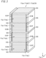
FIG. 3 is a perspective view of another example of the cell group (another example of the parallel series cell group) included in the battery pack; -
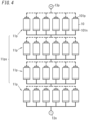
FIG. 4 is a conceptual view of another example of the cell group (another example of the parallel series cell group) included in the battery pack; -
FIG. 5 is a conceptual view of another example of the cell group (an example of a series parallel cell group) included in the battery pack; -
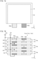
FIG. 6A is a top view of another example of the cell group (another example of the series parallel cell group) included in the battery pack; -
FIG. 6B is a side view of the another example ofFIG. 6A ; -
FIG. 7A is a top view of another example of the cell group (another example of the series parallel cell group) included in the battery pack; and -
FIG. 7B is a side view of the another example ofFIG. 7A . - Figures described in the embodiment described below are schematic views, and therefore, the ratio of sizes and the ratio of thicknesses of components in the drawings do not necessarily reflect actual dimensional ratios. Configurations described in the embodiment described below are a mere example of the present disclosure. The present disclosure is not limited to the embodiment described below. The embodiment may be modified in various manners depending on design or the like as long as the object of the present disclosure is achieved.
- An
electric tool 100 according to an embodiment of the present disclosure includes abattery pack 1, anelectric tool body 2, and atip tool 3, for example, as shown inFIG. 1 . Note that thetip tool 3 does not have to be included in components of theelectric tool 100. - The
electric tool 100 is, for example, an electrically driven screwdriver, an electrically driven drill, or the like. Note that theelectric tool 100 may be any tool as long as it includes thebattery pack 1 and is configured to be operated by electric power from thebattery pack 1. - The battery pack 1 supplies electric power to the
electric tool body 2. Thebattery pack 1 of the present embodiment is a battery pack including all-solid-state batteries. - The all-solid-state battery is a battery including a solid electrolyte. A current suppliable by the all-solid-state battery is smaller than (is, for example, only about 1/10) that in the case of a battery including a liquid electrolyte (electrolytic solution), whereas the amount of time for which the all-solid state battery can supply the current is greater than (is, for example, about 10 times) that in the case of the battery including the liquid electrolyte.
- Note that the
battery pack 1 in the present embodiment is attachable to and detachable from theelectric tool body 2 and is charged in a state where thebattery pack 1 is detached from theelectric tool body 2. Note that thebattery pack 1 may be charged in a state where thebattery pack 1 is attached to theelectric tool body 2. - The
battery pack 1 includes acell group 11. In the present embodiment, thecell group 11 includes a plurality ofcells 10 electrically connected to each other. Two ormore cells 10 included in thecell group 11 are each a single cell which is an all-solid-state battery. A connection between the two ormore cells 10 included in thecell group 11 may be a parallel connection, a series connection, or a combination of two types of connections, namely, the parallel connection and the series connection. - The
cell group 11 of the present embodiment includes six ormore cells 10 connected to each other, for example, as shown inFIGS. 2 to 7 . A connection among the six ormore cells 10 included in thecell group 11 is the combination of the parallel connection and the series connection. - Each of the
cells 10 in the present embodiment has a plate shape, for example, as shown inFIGS. 2 ,3 ,6 , and7 . The thickness of each of plate-shapedcells 10 is, for example, about 1 to several millimeters but may be less than 1 millimeter or may be greater than or equal to 10 millimeters. - Each of the plate-shaped
cells 10 has amajor surface 10m usually having a rectangular shape, for example, as shown inFIGS. 2 ,3 ,6 , and7 , but themajor surface 10m may have a shape (a polygonal shape such as a hexagonal shape, a circular shape, etc.) other than the rectangular shape. - Note that each
cell 10 is not limited to having the plate shape as shown inFIGS. 2 ,3 ,6 , and7 but may have a shape having an increased thickness. Examples of the shape having the increased thickness include a rectangular parallelepiped, a cube, and a circularly columnar shape. - Each
cell 10 may have a circularly columnar shape, for example, as shown inFIGS. 4 and5 . Note that the length in an axial direction is greater than the diameter of a bottom surface, of each of thecells 10 having the circularly columnar shape shown inFIGS. 4 and5 (e.g., a dry cell battery type), but the diameter of the bottom surface may be greater than the length in the axial direction (e.g., a button battery type). - Each
cell 10 is provided with electrodes. As described above, eachcell 10 of the present embodiment has the plate shape, and themajor surface 10m of eachcell 10 is rectangular. - Each
cell 10 has fourside surfaces 10s, and of the four side surfaces, twoside surfaces 10s opposite each other are provided with the electrodes, for example, as shown inFIGS. 2 and3 . - Specifically, the electrodes include a
positive pole 101p and anegative pole 101n. Thepositive pole 101p is a positive electrode, and thenegative pole 101n is a negative electrode. One (hereinafter referred to as oneside surface 10s) of the twoside surfaces 10s opposite each other is provided with thepositive pole 101p, and the other (hereinafter referred to as theother side surface 10s) of the twoside surfaces 10s opposite each other is provided with thenegative pole 101n. - The thickness and the depth of each of the electrodes (the
positive pole 101p and thenegative poles 101n) are respectively equal to, or substantially equal to, the thickness and the depth of a corresponding one of thecells 10, for example, as shown inFIGS. 2 ,3 ,6 , and7 . Moreover, the width of each of the electrodes (thepositive pole 101p and thenegative pole 101n) is, in the example shown inFIG. 2 and other figures, substantially 1/10 the width of a corresponding one of thecells 10 but may be less than, or greater than, 1/10 the width of the corresponding one of thecells 10. - Note that in the present embodiment, the thickness is a size in a Z-axis direction, the depth is a size in a Y direction, and the width is a size in an X direction. The Z axis is an axis extending vertically upward from a prescribed point (origin), and the X axis and the Y axis are each an axis passing through the origin, being perpendicular to the Z axis, and extending in directions perpendicular to each other (left and depth directions with respect to the paper surface).
- Note that in each
cell 10, the electrodes (thepositive pole 101p and thenegative pole 101n) may be disposed on oneside surface 10s. For example, acell 10 whosemajor surface 10m has a rectangular shape has fourside surfaces 10s, and of the fourside surfaces 10s, oneside surface 10s parallel to the X axis may be provided with both apositive pole 101p and anegative pole 101n as shown inFIGS. 6A and7A . - Specifically, the
positive pole 101p and thenegative pole 101n may be disposed within the oneside surface 10s and at different heights (within different horizontal planes), while aninsulator 103 is disposed between thepositive pole 101p and thenegative pole 101n, for example, as shown inFIG. 6A . - Alternatively, the
positive pole 101p and thenegative pole 101n may be disposed within the oneside surface 10s and at the same height (within the same horizontal plane), while a prescribed space is provided between thepositive pole 101p and thenegative pole 101n, for example, as shown inFIG. 7A . - Note that in the present embodiment, the height is a location (e.g., a Z-coordinate) in the Z-axis direction, and the horizontal plane is a plane perpendicular to the Z axis.
- For example, a
cylindrical cell 10 has two bottom surfaces, and one bottom surface of the two bottom surfaces is provided with apositive pole 101p, and the other bottom surface of the two bottom surfaces is provided with anegative pole 101n as shown inFIGS. 4 and5 . - The
cell group 11 includes electrode groups. Each of the electrode groups is a group obtained by connecting to each other the electrodes (thepositive poles 101p, thenegative poles 101n) having the same polarity and provided to the plurality ofcells 10 included in thecell group 11. - The electrode group includes a
positive pole group 101P and anegative pole group 101N. Thepositive pole group 101P includes thepositive poles 101p each of which is on oneside surface 10s of a corresponding one of the two ormore cells 10 included in thecell group 11 and which are connected to each other. Thenegative pole group 101N includes thenegative poles 101n each of which is on theother side surface 10s of the corresponding one of the two ormore cells 10 included in thecell group 11 and which are connected to each other. - In the present embodiment, the
positive poles 101p each disposed on oneside surface 10s of a corresponding one of the plurality of plate-shapedcells 10 included in thecell group 11 are directly connected to each other, thereby forming thepositive pole group 101P, for example, as shown inFIGS. 2 and3 . Moreover, thenegative poles 101n each disposed on theother side surface 10s of the corresponding one of the plurality of plate-shapedcells 10 included in thecell group 11 are directly connected to each other, thereby forming thenegative pole group 101N. - The
battery pack 1 includes ahousing 12 configured to house thecell group 11, and a terminal 13 protruding from an interior beyond an outer surface of thehousing 12. The terminal 13 is connected to the electrode groups (thepositive pole group 101P and thenegative pole group 101N) included in thecell group 11 in thehousing 12. - The terminal 13 includes a positive terminal 13p and a
negative terminal 13n. Thepositive terminal 13p is connected to thepositive pole group 101P, and thenegative terminal 13n is connected to thenegative pole group 101N. - The
electric tool body 2 is operated by electric power from thebattery pack 1. Specifically, theelectric tool body 2 includes a body terminal (not shown). The body terminal includes a body positive terminal and a body negative terminal (which are not shown). - When the
battery pack 1 is attached to theelectric tool body 2, the terminal 13 (the positive terminal 13p and thenegative terminal 13n) of thebattery pack 1 is connected to the body terminal (the body positive terminal and the body negative terminal), and thereby, theelectric tool body 2 can be operated by the electric power from thebattery pack 1. - As shown in
FIG. 1 , theelectric tool body 2 includes anattachment 21 to which thetip tool 3 is to be attached, adriver 22 configured to convert the electric power from thebattery pack 1 into rotational force, atransmitter 23 configured to transmit the rotational force from thedriver 22 to theattachment 21, and other components. - The
tip tool 3 is, for example, a screwdriver bit, as shown inFIG. 1 , for screw tightening work but may be, for example, a drill bit for a hole forming process, that is, thetip tool 3 may be of any type. - In a state where the
battery pack 1 is attached to theelectric tool body 2 and thetip tool 3 is also attached to theattachment 21 of theelectric tool body 2, a prescribed operation (e.g., an operation such as engaging thetip tool 3 with an object such as a screw and pulling a trigger of the electric tool) is given to theelectric tool body 2, thereby supplying the electric power from thecell group 11 via the electrode group (thepositive pole group 101P and thenegative pole group 101N) and the body terminal (the body positive terminal and the body negative terminal) to theelectric tool body 2. - In the
electric tool body 2, thedriver 22 converts the electric power from thebattery pack 1 into rotational force, and the rotational force from thedriver 22 is transmitted via thetransmitter 23 to theattachment 21. This rotates thetip tool 3 attached to theattachment 21, thereby tightening the object such as the screw with which thetip tool 3 has been engaged. - The connection among the six or
more cells 10 included in thecell group 11 is a combination of two types of connections, namely, the parallel connection and the series connection. - The
cell group 11 in the present embodiment is a parallel series cell group 11ps or a series parallel cell group 11sp. - The parallel series cell group 11ps includes two or more
parallel cell groups 11p connected in series to each other, for example, as shown inFIGS. 2 to 4 . Eachparallel cell group 11p includes three ormore cells 10 connected in parallel to each other. - The parallel series cell group 11ps shown in each of
FIGS. 2 to 6 includes fourparallel cell groups 11p which are connected in series to each other and each of which includes sixcells 10 connected in parallel to each other. - The series parallel cell group 11sp includes three or more
series cell groups 11s connected in parallel to each other as shown inFIGS. 5 to 7 . Eachseries cell group 11s includes two ormore cells 10 connected in series to each other. - The series parallel cell group 11sp shown in
FIG. 5 includes sixseries cell groups 11s which are connected in parallel to each other and each of which includes fourcells 10 connected in series to each other. - The series parallel cell group 11sp shown in each of
FIGS. 6 and7 includes threeseries cell groups 11s which are connected in parallel to each other and each of which includes twocells 10 connected in series to each other. - Here, in the cell group 11 (the parallel series cell group 11ps or the series parallel cell group 11sp) of the present embodiment, a parallel number is greater than a series number.
- The parallel number is the number of
cells 10 included in eachparallel cell group 11p or the number ofseries cell groups 11s included in the series parallel cell group 11sp. - The series number is the number of
cells 10 included in eachseries cell group 11s or the number ofparallel cell groups 11p included in the parallel series cell group 11ps. - That is, when the parallel number is denoted by "i" and the series number is denoted by "j", "i is an integer greater than or equal to 3", "j is an integer greater than or equal to 2", and the inequality expression "i > j" holds true.
- Note that the parallel series cell group 11ps including j
parallel cell groups 11p which are connected in series to each other and each of which includes icells 10 connected in parallel to each other may be represented as "i-parallel j-series cell group". Moreover, the series parallel cell group 11sp including iseries cell groups 11s which are connected in parallel to each other and each of which includesj cells 10 connected in series to each other may be represented as "j-series i-parallel cell group". - According to this notational method, the parallel series cell group 11ps shown in each of
FIGS. 2A, 2B ,3 , and4 is a "6-parallel 4-series cell group" including fourparallel cell groups 11p which are connected in series to each other and each of which includes sixcells 10 connected in parallel to each other. - Moreover, the series parallel cell group 11sp shown in
FIG. 5 is a "4-series 6-parallel cell group" including sixseries cell groups 11s which are connected in parallel to each other and each of which includes fourcells 10 connected in series to each other. - Moreover, the series parallel cell group 11sp shown in each of
FIGS. 6B and7B is a "2-series 3-parallel cell group" including threeseries cell groups 11s which are connected in parallel to each other and each of which includes twocells 10 connected in series to each other. - As described above, in the
cell group 11 including the six ormore cells 10 connected to each other in the combination of the parallel connection and the series connection, the parallel number is set to be greater than the series number, thereby implementing abattery pack 1 which includes all-solid-state batteries and which leads to improved reliability regarding damage caused by, for example, an impact. Moreover, thebattery pack 1 configured as described above is provided to anelectric tool 100, so that theelectric tool 100 leads to improved reliability. - Thus, as a result of the improved reliability, stacking an increased number of all-solid-state batteries having a reduced thickness one on top of another can provide a
battery pack 1 including the all-solid-state batteries and configured to increase at least one of the capacity or the voltage while the size is suppressed from increasing and anelectric tool 100 including thebattery pack 1 configured as described above. - For example, in the 6-parallel 4-series cell group 11ps shown in
FIG. 4 , twocells 10 of 24cells 10 are assumed to be damaged. The twocells 10 are asecond cell 10 from the left in a secondparallel cell group 11p from the top and afirst cell 10 from the left in a thirdparallel cell group 11p from the top. - In this case, in each of the second
parallel cell group 11p from the top and the thirdparallel cell group 11p from the top, fivecells 10 except for the one damaged cell function. Therefore, thebattery pack 1 including the 6-parallel 4-series cell group 11ps as a whole can maintain the value of a voltage in the case of no damage and can secure a current having a value of 5/6 that in the case of no damage. - Further, even when in the 6-parallel 4-series cell group lips shown in
FIG. 4 , two cells in oneparallel cell group 11p (e.g., the secondparallel cell group 11p from the top) are damaged, the remaining fourcells 10 function. Therefore, thebattery pack 1 including the 6-parallel 4-series cell group 11ps as a whole can maintain the value of a voltage in the case of no damage and can secure a current having a value of 4/6 that in the case of no damage. - Furthermore, even when in the 6-parallel 4-series cell group 11ps shown in
FIG. 4 , four cells equal to the series number in the oneparallel cell group 11p are damaged, the remaining twocells 10 function. Therefore, thebattery pack 1 including the 6-parallel 4-series cell group 11ps as a whole can maintain the value of a voltage in the case of no damage and can secure a current having a value of 2/6 that in the case of no damage. - Note that the 6-parallel 4-series cell group lips of each of
FIGS. 2A and3 can also provide the effect of maintaining the voltage and securing the current similarly to the above case. - In general, even when in an i-parallel j-series cell group 11ps, the same number of
cells 10 as the series number j in oneparallel cell group 11p are damaged, the remaining (i-j)cells 10 function. Therefore, abattery pack 1 including the i-parallel j-series cell group 11ps as a whole can maintain the value of a voltage in the case of no damage and can secure a current having a value of {(i-j)/i} that in the case of no damage. - Thus, this holds true as long as "i > j" even when the parallel number i and/or the series number j increases. Therefore, the
battery pack 1 including the parallel series cell group lips leads to improved reliability regarding damage caused by, for example, an impact. Moreover, as a result of the improved reliability, at least one of the capacity or the voltage can be increased. - For example, in the 4-series 6-parallel cell group 11sp shown in
FIG. 5 , twocells 10 of 24cells 10 are assumed to be damaged. The twocells 10 are athird cell 10 from the top in a firstseries cell group 11s from the left and asecond cell 10 from the top in a secondseries cell group 11s from the left. - In this case, two series cell groups, namely, the first and second
series cell groups 11s from the left no longer function, but four series cell groups, namely, third to sixthseries cell groups 11s from the left function. Therefore, thebattery pack 1 including the 4-series 6-parallel cell group 11sp as a whole can maintain the value of a voltage in the case of no damage and can secure a current having a value of 4/6 that in the case of no damage. - Note that the 2-series 4-parallel cell group 11sp of each of
FIGS. 6B and7B can also provide the effect of maintaining the voltage and securing the current similarly to the above case. - In general, even when in a j-series i-parallel cell group 11sp, one
cell 10 in each of the same number ofseries cell groups 11s as the series number j is damaged, (i-j)series cell groups 11s function. Therefore, thebattery pack 1 including the j-series i-parallel cell group 11sp as a whole can maintain the value of a voltage in the case of no damage and can secure a current having a value of {(i-j)/i} that in the case of no damage. - Thus, this holds true as long as "i > j" even when the parallel number i and/or the series number j increases. Therefore, the
battery pack 1 including the series parallel cell group 11sp leads to improved reliability regarding damage caused by, for example, an impact. Moreover, as a result of the improved reliability, at least one of the capacity or the voltage can be increased. - In the present embodiment, the
cell group 11 as described above is formed by stacking a plurality of plate-shapedcells 10 one on top of another, thereby increasing at least one of the capacity or the voltage while the size of thebattery pack 1 is suppressed from increasing. - Specifically, each
cell 10 of the present embodiment is, for example, plate-shaped as described above and has the side surfaces 10s provided with the electrodes. Two or more such plate-shapedcells 10 are stacked one on top of another such that themajor surfaces 10m overlap each other, and the electrodes on the side surfaces 10s of the two ormore cells 10 stacked one on top of another are connected to each other, thereby forming a stacked cell (seeFIGS. 2 ,3 ,6 , and7 ). - Note that the two or
more cells 10 included in the stacked cell are directly stacked one on top of another, for example, as shown inFIGS. 2 and3 but may be stacked while aspacer 102 is disposed between thecells 10 as shown inFIGS. 6 and7 . - The electrodes of the two or
more cells 10 included in the stacked cell may be connected to each other directly or via a conductor. - Moreover, the connection between the electrodes of the two or
more cells 10 included in the stacked cell may be the parallel connection or the series connection. - In the present embodiment, the two or
more cells 10 are stacked one on top of another such that electrodes having the same polarity are arranged on the same side of twoside surfaces 10s opposite each other, for example, as shown inFIGS. 2 and3 . Thus, the electrodes, which have the same polarity, of the two ormore cells 10 are directly connected to each other (thepositive poles 101p are directly connected to each other, and thenegative poles 101n are directly connected to each other), thereby implementing the parallel connection. - Note that, when the
positive pole 101p and thenegative pole 101n are disposed on oneside surface 10s of each of two ormore cells 10 stacked while thespacer 102 disposed between the two ormore cells 10, for example, as shown inFIGS. 6 and7 , thepositive pole 101p and thenegative pole 101n of the two ormore cells 10 may be connected to each other via a conductor such as a conductor wire, thereby implementing the series connection. - In general, the stacked cell is classified into a parallel stacked cell 11pL or a series stacked cell 11sL depending on whether the connection between the electrodes of the two or
more cells 10 is the parallel connection or the series connection. - The parallel stacked cell 11pL includes two or
more cells 10 stacked one on top of another such that themajor surfaces 10m overlap each other, the two ormore cells 10 including:positive poles 101p each of which is disposed on one of the side surfaces 10s of a corresponding one of the two ormore cells 10 and which are connected to each other to form thepositive pole group 101P; andnegative poles 101n each of which is disposed on the other of the side surfaces 10s of the corresponding one of the two ormore cells 10 and which are connected to each other to form thenegative pole group 101N. - In the parallel stacked cell 11pL of the present embodiment, the
positive poles 101p are directly connected to each other, and thenegative poles 101n are directly connected to each other. - As described above, the
cell group 11 is formed as the stacked cell (the parallel stacked cell 11pL or the series stacked cell 11sL) including the plate-shapedcells 10 stacked one on top of another, thereby implementing abattery pack 1 which includes all-solid-state batteries and which leads to improved reliability and a reduced size. - Moreover, the
cell group 11 is configured to be in the aspect of the parallel stacked cell 11pL including plate-shapedcells 10 which are connected in parallel to each other and which are stacked one on top of another, thereby implementing abattery pack 1 which includes all-solid-state batteries and which leads to an increased capacity, improved reliability, and a reduced size. - Further, a plurality of the parallel stacked cells 11pL are coupled to each other in the series connection, thereby implementing a
battery pack 1 which includes all-solid-state batteries and which leads to an increased capacity, improved reliability, a reduced size, and an increased voltage. - The series stacked cell 11sL includes two or
more cells 10 stacked such that themajor surfaces 10m overlap each other while thespacer 102 is disposed between the two ormore cells 10, wherein in a set of thepositive pole 101p on theside surface 10s of one (hereinafter referred to as a first cell 10) of twoadjacent cells 10 of the two ormore cells 10 stacked one on top of another and thenegative pole 101n on theside surface 10s of the other (hereinafter referred to as a second cell 10) of the twoadjacent cells 10, or in a set of thenegative pole 101n on theside surface 10s of thefirst cell 10 and thepositive pole 101p on theside surface 10s of thesecond cell 10, thepositive pole 101p and thenegative pole 101n are connected to each other via a conductor. - Note that the stacked cell (the parallel stacked cell 11pL or the series stacked cell 11sL) may be a combination of the parallel stacked cell 11pL and the series stacked cell 11sL, for example, as shown in
FIGS. 6B and7B . -
FIGS. 6B and7B show the series parallel cell group 11sp as described above, and the series parallel cell group lisp is specifically the "2-series 3-parallel cell group" including threeseries cell groups 11s which are connected in parallel to each other and each of which includes twocells 10 connected in series to each other. - The "2-series 3-parallel cell group" in
FIG. 6B includes six cells 10 (see First Variation of Electrodes) ofFIG. 6A stacked while thespacers 102 are each disposed between adjacent two of the sixcells 10, and the electrodes are connected to each other as follows. That is, between two cells, namely, first andsecond cells 10 from the top (hereinafter referred to as a "first cell" and a "second cell"), thenegative pole 101n of the first cell is connected to thepositive pole 101p of the second cell, thepositive pole 101p of the first cell is connected to thepositive terminal 13p, and thenegative pole 101n of the second cell is connected to thenegative terminal 13n. - Further, between two cells, namely, third and
fourth cells 10 from the top (hereinafter referred to as a "third cell" and a "fourth cell"), thenegative pole 101n of the third cell is connected to thepositive pole 101p of the fourth cell, thepositive pole 101p of the third cell is connected to thepositive terminal 13p, and thenegative pole 101n of the fourth cell is connected to thenegative terminal 13n. - Furthermore, between two cells, namely, fifth and
sixth cells 10 from the top (hereinafter referred to as a "fifth cell" and a "sixth cell"), thenegative pole 101n of the fifth cell is connected to thepositive pole 101p of the sixth cell, thepositive pole 101p of the fifth cell is connected to thepositive terminal 13p, and thenegative pole 101n of the sixth cell is connected to thenegative terminal 13n. - The "2-series 3-parallel cell group" in
FIG. 7B includes six cells 10 (see Second Variation of Electrodes) ofFIG. 7A stacked whilespacers 102 are each disposed between adjacent two of the sixcells 10, wherein the electrodes are connected to each other as described below. That is, the positional relationship between thepositive pole 101p and thenegative pole 101n of first, fourth, andfifth cells 10 from the top (hereinafter referred to as a "first cell", a "fourth cell", and a "fifth cell") is the same as that inFIG. 7A , whereas the positional relationship between thepositive pole 101p and thenegative pole 101n of second, third, andsixth cells 10 from the top (hereinafter referred to as a "second cell", a "third cell", and a "sixth cell") is opposite (reverse) to that shown inFIG. 7A . - Here, while a distance corresponding to the thickness of the
spacer 102 is provided between the first cell and the second cell, thepositive pole 101p of the first cell and thenegative pole 101n of the second cell in a set face each other, thenegative pole 101n of the first cell and thepositive pole 101p of the second cell in a set face each other, and thenegative pole 101n and thepositive pole 101p in the latter set of the two sets are connected to each other via a conductor. - Moreover, while the distance corresponding to the thickness of the
spacer 102 is provided between the second cell and the third cell, thenegative pole 101n of the second cell and thenegative pole 101n of the third cell in a set face each other, thepositive pole 101p of the second cell and thepositive pole 101p of the third cell in a set face each other, and thenegative pole 101n and thenegative pole 101n in the former set are connected to each other via a conductor. - Further, while the distance corresponding to the
spacer 102 provided between the third cell and the fourth cell, thenegative pole 101n of the third cell and thepositive pole 101p of the fourth cell in a set face each other, thepositive pole 101p of the third cell and thenegative pole 101n of the fourth cell in a set face each other, and thepositive pole 101p and thenegative pole 101n in the latter set are connected to each other via a conductor. - Furthermore, while the distance corresponding to the
spacer 102 is provided between the fourth cell and the fifth cell, thepositive pole 101p of the fourth cell and thepositive pole 101p of the fifth cell in a set face each other, thenegative pole 101n of the fourth cell and thenegative pole 101n of the fifth cell in a set face each other, and thepositive pole 101p and thepositive pole 101p in the former set are connected to each other via a conductor. - Moreover, while the distance corresponding to the
spacer 102 is provided between the fifth cell and the sixth cell, thepositive pole 101p of the fifth cell and thenegative pole 101n of the sixth cell in a set face each other, thenegative pole 101n of the fifth cell and thepositive pole 101p of the sixth cell in a set face each other, and thenegative pole 101n and thepositive pole 101p in the latter set of the two sets are connected to each other via a conductor. - The parallel series cell group 11ps of the present embodiment is, for example, a coupled cell 11pLC. The coupled cell 11pLC includes two or more parallel stacked cells 11pL as described above, the two or more parallel stacked cells 11pL being coupled such that the
positive pole group 101P and thenegative pole group 101N are connected to each other (i.e., in series connection). - The coupled cell 11pLC of the present embodiment is a first coupled cell 11pLCa as shown in, for example,
FIG. 2 . The first coupled cell 11pLCa includes two or more parallel stacked cells 11pL coupled to each other in a direction parallel to themajor surfaces 10m. - In the first coupled cell 11pLCa, the
positive pole group 101P of one parallel stacked cell 11pL and thenegative pole group 101N of the other parallel stacked cell 11pL of the parallel stacked cells 11pL adjacent to each other are aligned in a direction (X-axis direction) from oneside surface 10s to theother side surface 10s of each of thecells 10. This leads to downsizing in a direction perpendicular to themajor surfaces 10m (e.g., thinning). - In the first coupled cell 11pLCa of the present embodiment, the
positive pole group 101P and thenegative pole group 101N are directly connected to each other as shown in, for example,FIG. 2A . - Note that in the first coupled cell 11pLCa, the
positive pole group 101P and thenegative pole group 101N may be connected to each other via aconductor 105 as shown inFIG. 2B . Theconductor 105 thus provided can improve the electrical conductivity between thepositive pole group 101P and thenegative pole group 101N. - The coupled cell 11pLC including the parallel stacked cells 11pL coupled to each other in the series connection implements the
battery pack 1 which includes all-solid-state batteries and which leads to an increased capacity, improved reliability, a reduced size, and an increased voltage. - Note that the coupled cell 11pLC may be a second coupled cell 11pLCb as shown in
FIG. 3 . The second coupled cell 11pLCb includes two or more parallel stacked cells 11pL coupled to each other in a direction perpendicular to themajor surfaces 10m via theinsulator 103. - In the second coupled cell 11pLCb, the
positive pole group 101P of one parallel stacked cell 11pL of two adjacent parallel stacked cells 11pL and thenegative pole group 101N of the other parallel stacked cell 11pL of the two adjacent parallel stacked cells 11pL in a set are aligned with each other in a direction perpendicular to themajor surfaces 10m (in the Z-axis direction), and thenegative pole group 101N of the one parallel stacked cell 11pL and thepositive pole group 101P of the other parallel stacked cell 11pL in a set are aligned with each other in the direction perpendicular to themajor surfaces 10m . - The
insulator 103 is disposed at a portion between the parallel stacked cells 11pL adjacent to each other except for a portion between thepositive pole group 101P and thenegative pole group 101N in one of the two sets. Thepositive pole group 101P and thenegative pole group 101N in the one of the two sets are connected to each other via theconductor 105. - This leads to downsizing in a direction parallel to the
major surfaces 10m (e.g., slenderizing). - Note that the
conductor 105 in the present embodiment is a plate-like conductor extending in a direction perpendicular to themajor surfaces 10m as shown in, for example,FIG. 3 . Theconductor 105 is connected to substantially the entirety of each of thepositive pole group 101P and thenegative pole group 101N included in the one of the two sets. This leads to improved electrical conductivity and improved strength between thepositive pole group 101P and thenegative pole group 101N. - Note that the
conductor 105 may have the same thickness (size in the Z direction) as theinsulator 103 and may be disposed between thepositive pole group 101P and thenegative pole group 101N included in the one of the two sets. This leads to further downsizing in the direction parallel to themajor surfaces 10m. - A battery pack (1) of a first aspect includes a cell group (11) including a plurality of cells (10) which are all-solid-state batteries and which are electrically connected to each other. The cell group (11) is a parallel series cell group (11ps) or a series parallel cell group (11sp). The parallel series cell group (11ps) includes two or more parallel cell groups (11p) connected in series to each other. Each of the two or more parallel cell groups (11p) includes, as the plurality of cells (10), three or more cells (10) connected in parallel to each other. The series parallel cell group (11sp) includes three or more series cell groups (11s) connected in parallel to each other. Each of the three or more series cell groups (11s) includes, as the plurality of cells (10), two or more cells (10) connected in series to each other. In the cell group (11), a parallel number (i: i is an integer greater than or equal to 3) is greater than a series number(j: j is an integer greater than or equal to 3) (parallel number i > series number j). The parallel number (i) is a number of the plurality of cells (10) included in each of the two or more parallel cell groups (11p) or a number of the three or more series cell groups (11s) included in the series parallel cell group (11sp). The series number (j) is a number of the plurality of cells (10) included in each of the three or more series cell groups (11s) or a number of the two or more parallel cell groups (11p) included in the parallel series cell group (11ps).
- With this aspect, the series number(j) is set to be greater than the parallel number (i), thereby implementing the battery pack (1) including the all-solid-state batteries and leading to improved reliability.
- In a battery pack (1) of a second aspect referring to the first aspect, each of the plurality of cells (10) has a plate shape and has side surfaces (10s) provided with electrodes (101p, 101n). The cell group (11) is a stacked cell (11pL, 11sL). The stacked cell (11pL, 11sL) includes, as the plurality of cells (10), two or more cells (10) stacked one on top of another such that major surfaces (10m) of the two or more cells (10) overlap each other, the electrodes (101p, 101n) on the side surfaces (10s) of the two or more cells (10) being connected to each other.
- With this aspect, the stacked cell (11pL, 11sL) including the cells (10) each of which is plate-shaped and which are stacked one on top of another implements the battery pack (1) including the all-solid-state batteries and leading to improved reliability and a reduced size.
- In a battery pack (1) of a third aspect referring to the second aspect, the side surfaces (10s) include two side surfaces (10s) opposite each other. The two side surfaces (10s) include one side surface (10s) on which a positive pole (101p) is disposed and the other side surface (10s) on which a negative pole (101n) is disposed. The positive pole (101p) is a positive electrode, and the negative pole (101n) is a negative electrode. The cell group (11) is the parallel series cell group (11ps). The two or more parallel cell groups (11p) included in the parallel series cell group (11ps) are two or more parallel stacked cells (11pL). Each of the parallel stacked cells (11pL) includes, as the plurality of cells (10), two or more cells (10) stacked one on top of another such that the major surfaces (10m) of the two or more cells (10) overlap each other. The two or more cells (10) include: the positive pole (101p) such that the two or more cells (10) include positive poles (101p) each of which is disposed on the one side surface and which are connected to each other to form the positive pole group (101P); and the negative pole (101n) such that the two or more cells (10) include negative poles (101n) each of which is disposed on the other side surface and which are connected to each other to from the negative pole group (101N).
- With this aspect, the parallel stacked cell (11pL) including the plurality of cells (10) each of which is plate-shaped and which are connected in parallel to each other and are stacked on one another implements the battery pack (1) including the all-solid-state batteries and leading to an increased capacity, improved reliability, and a reduced size.
- In a battery pack (1) of a fourth aspect referring to the third aspect, the parallel series cell group (11ps) is a coupled cell (11pLC). The coupled cell (11pLC) includes the two or more parallel stacked cells (11pL), the two or more parallel stacked cells (11pL) being coupled to each other such that at least one of the positive pole group (101P) or the negative pole group (101N) of one of two adjacent parallel stacked cells (11pL) of the two or more parallel stacked cells (11pL) is respectively connected to the negative pole group (101N) or the positive pole group (101P) of the other of the two adjacent parallel stacked cells (11pL).
- With this aspect, coupling the parallel stacked cells (11pL) in the series connection implements the battery pack (1) including all-solid-state batteries and leading to an increased capacity, improved reliability, a reduced size, and an increased voltage.
- In a battery pack (1) of a fifth aspect referring to the fourth aspect, the coupled cell (11pLC) is a first coupled cell (11pLCa). The first coupled cell (11pLCa) includes the two or more parallel stacked cells (11pL), the two or more parallel stacked cells (11pL) being coupled to each other in a direction parallel to the major surfaces (10m). The positive pole group (101P) or the negative pole group (101N) of one parallel stacked cell (11pL) of two adjacent parallel stacked cells (11pL) of the two or more parallel stacked cells (11pL) included in the first coupled cell (11pLCa) is respectively connected to the negative pole group (101N) or the positive pole group (101P) of the other parallel stacked cell (11pL) of the two adjacent parallel stacked cells (11pL) directly or via a conductor (105).
- With this aspect, coupling the parallel stacked cells (11pL) in a direction parallel to the major surfaces (10m) leads to downsizing in a direction perpendicular to the major surfaces (10m) (e.g., thinning).
- In a battery pack (1) of a sixth aspect referring to the fourth aspect, the coupled cell (11pLC) is a second coupled cell (11pLCb). The second coupled cell (11pLCb) includes the two or more parallel stacked cells (11pL). The two or more parallel stacked cells (11pL) are coupled to each other in a direction perpendicular to the major surfaces (10m) via an insulator (103). The positive pole group (101P) of one parallel stacked cell (11pL) of two adjacent parallel stacked cells (11pL) of the two or more parallel stacked cells (11pL) included in the second coupled cell (11pLCb) and the negative pole group (101N) of the other parallel stacked cell (11pL) of the two adjacent parallel stacked cells (11pL) in a set are aligned with each other in the direction perpendicular to the major surfaces (10m). The negative pole group (101N) of the one parallel stacked cell (11pL) and the positive pole group (101P) of the other parallel stacked cell (11pL) in a set are aligned with each other in the direction perpendicular to the major surfaces (10m). The insulator (103) is disposed at a portion between the two adjacent parallel stacked cells (11pL) except for a portion between the positive pole group (101P) and the negative pole group (101N) in one of the sets. The positive pole group (101P) and the negative pole group (101N) in the one of the sets are connected to each other via a conductor (105).
- With this aspect, coupling the parallel stacked cells (11pL) in the direction perpendicular to the major surfaces (10m) via the insulator leads to downsizing in a direction parallel to the major surfaces (10m) (e.g., slenderizing).
- An electric tool (100) of a seventh aspect includes: the battery pack (1) of any one of the first to sixth aspects; and an electric tool body (2) configured to be operated by electric power from the battery pack (1).
- With this aspect, the series number(j) is set to be greater than the parallel number (i), thereby implementing the electric tool (100) which includes the battery pack (1) including all-solid-state batteries and which leads to improved reliability.
-
- 100
- Electric Tool
- 1
- Battery Pack
- 10
- Cell
- 10m
- Major surface
- 10s
- Side Surface (One Side Surface, The Other Side Surface)
- 101p
- Positive Pole
- 101P
- Positive Pole Group
- 101n
- Negative Pole
- 101N
- Negative Pole Group
- 11
- Cell Group
- 11p
- Parallel Cell Group
- lips
- Parallel series Cell Group
- 11s
- Series Cell Group
- lisp
- Series parallel Cell Group
- 11pL
- Parallel Stacked Cell
- 11pLC
- Coupled Cell
- 11pLCa
- First Coupled Cell
- 11pLCb
- Second Coupled Cell
- 11sL
- Series Stacked Cell
- 12
- Housing
- 13
- Terminal
- 13p
- Positive Terminal
- 13n
- Negative Terminal
- 2
- Electric Tool Body
- 21
- Attachment
- 22
- Driver
- 23
- Transmitter
- 3
- Tip Tool
Claims (7)
- A battery pack comprising a cell group including a plurality of cells which are all-solid-state batteries and which are electrically connected to each other,the cell group beinga parallel series cell group including two or more parallel cell groups which are connected in series to each other and each of which includes, as the plurality of cells, three or more cells connected in parallel to each other ora series parallel cell group including three or more series cell groups which are connected in parallel to each other and each of which includes, as the plurality of cells, two or more cells connected in series to each other,in the cell group, a parallel number which is a number of the plurality of cells included in each of the two or more parallel cell groups or a number of the three or more series cell groups included in the series parallel cell group being greater than a series number which is a number of the plurality of cells included in each of the three or more series cell group or a number of the two or more parallel cell groups included in the parallel series cell group.
- The battery pack of claim 1, whereineach of the plurality of cells has a plate shape and has side surfaces provided with electrodes, andthe cell group is a stacked cell including, as the plurality of cells, two or more cells stacked one on top of another such that major surfaces of the two or more cells overlap each other, the electrodes on the side surfaces of the two or more cells being connected to each other.
- The battery pack of claim 2, whereinthe side surfaces include two side surfaces opposite each other,the two side surfaces includeone side surface on which a positive pole which is a positive electrode is disposed andthe other side surface on which a negative pole which is a negative electrode is disposed,the cell group is the parallel series cell group, andthe two or more parallel cell groups included in the parallel series cell group are two or more parallel stacked cells, each of the two or more parallel stacked cells including, as the plurality of cells, two or more cells, stacked one on top of another such that the major surfaces of the two or more cells overlap each other, the two or more cells including the positive pole such that the two or more cells include positive poles each of which is disposed on the one side surface and which are connected to each other to form the positive pole group and the negative pole such that the two or more cells include negative poles each of which is disposed on the other side surface and which are connected to each other to from the negative pole group.
- The battery pack of claim 3, wherein
the parallel series cell group is a coupled cell including the two or more parallel stacked cells, the two or more parallel stacked cells being coupled to each other such that at least one of the positive pole group or the negative pole group of one of two adjacent parallel stacked cells of the two or more parallel stacked cells is respectively connected to the negative pole group or the positive pole group of the other of the two adjacent parallel stacked cells. - The battery pack of claim 4, whereinthe coupled cell is a first coupled cell including the two or more parallel stacked cells, the two or more parallel stacked cells being coupled to each other in a direction parallel to the major surfaces, andthe positive pole group or the negative pole group of one of two adjacent parallel stacked cells of the two or more parallel stacked cells included in the first coupled cell are respectively connected to the negative pole group or the positive pole group of the other of the two adjacent parallel stacked cells directly or via a conductor.
- The battery pack of claim 4, whereinthe coupled cell is a second coupled cell including the two or more parallel stacked cells, the two or more parallel stacked cells being coupled to each other in a direction perpendicular to the major surfaces via an insulator,the positive pole group of one parallel stacked cell of two adjacent parallel stacked cells of the two or more parallel stacked cells included in the second coupled cell and the negative pole group of the other parallel stacked cell of the two adjacent parallel stacked cells in a set are aligned with each other in the direction perpendicular to the major surfaces,the negative pole group of the one parallel stacked cell and the positive pole group of the other parallel stacked cell in a set are aligned with each other in the direction perpendicular to the major surfaces,the insulator is disposed at a portion between the two adjacent parallel stacked cells except for a portion between the positive pole group and the negative pole group in one of the sets, andthe positive pole group and the negative pole group in the one of the sets are connected to each other via a conductor.
- An electric tool comprising:the battery pack of any one of claims 1 to 6; andan electric tool body configured to be operated by electric power from the battery pack.
Applications Claiming Priority (2)
| Application Number | Priority Date | Filing Date | Title |
|---|---|---|---|
| JP2021150437A JP2023042986A (en) | 2021-09-15 | 2021-09-15 | Battery pack and electric power tool |
| PCT/JP2022/012369 WO2023042446A1 (en) | 2021-09-15 | 2022-03-17 | Battery pack and electric tool |
Publications (2)
| Publication Number | Publication Date |
|---|---|
| EP4404319A1 true EP4404319A1 (en) | 2024-07-24 |
| EP4404319A4 EP4404319A4 (en) | 2025-05-07 |
Family
ID=85601965
Family Applications (1)
| Application Number | Title | Priority Date | Filing Date |
|---|---|---|---|
| EP22869598.7A Withdrawn EP4404319A4 (en) | 2021-09-15 | 2022-03-17 | BATTERY PACK AND POWER TOOL |
Country Status (5)
| Country | Link |
|---|---|
| US (1) | US20240405378A1 (en) |
| EP (1) | EP4404319A4 (en) |
| JP (1) | JP2023042986A (en) |
| CN (1) | CN117795752A (en) |
| WO (1) | WO2023042446A1 (en) |
Families Citing this family (2)
| Publication number | Priority date | Publication date | Assignee | Title |
|---|---|---|---|---|
| JP2025000400A (en) * | 2023-06-19 | 2025-01-07 | パナソニックIpマネジメント株式会社 | Charging system, charging device, battery pack, and power tool |
| JP2025002090A (en) * | 2023-06-21 | 2025-01-09 | パナソニックIpマネジメント株式会社 | Charging system, charging device, battery pack, and power tool |
Family Cites Families (11)
| Publication number | Priority date | Publication date | Assignee | Title |
|---|---|---|---|---|
| US6441582B1 (en) * | 2000-03-29 | 2002-08-27 | Koninklijke Phillips Electronics N.V. | Battery arrangement for improved defibrillator safety |
| JP5135664B2 (en) * | 2003-12-05 | 2013-02-06 | 日産自動車株式会社 | Cathode material for non-aqueous electrolyte lithium ion battery and battery using the same |
| US20060129192A1 (en) * | 2004-11-22 | 2006-06-15 | Wilson Greatbatch | High-energy battery power source for implantable medical use |
| US20090291361A1 (en) * | 2008-05-20 | 2009-11-26 | Dino Scorziello | Wearable power supply for soldiers |
| CN105990609B (en) * | 2015-02-03 | 2019-01-29 | 微宏动力系统(湖州)有限公司 | Battery |
| CN110392944A (en) * | 2017-03-07 | 2019-10-29 | 远景Aesc日本有限公司 | Method for manufacturing battery pack |
| US20190089023A1 (en) * | 2017-09-15 | 2019-03-21 | Dyson Technology Limited | Energy storage system |
| JP2019160498A (en) * | 2018-03-09 | 2019-09-19 | 三菱重工業株式会社 | All-solid battery module and all-solid battery unit |
| JP7507097B2 (en) * | 2019-01-16 | 2024-06-27 | 株式会社半導体エネルギー研究所 | Semiconductor Device |
| JP7266214B2 (en) * | 2019-09-30 | 2023-04-28 | パナソニックIpマネジメント株式会社 | Power tools and battery packs |
| US20210218048A1 (en) * | 2020-01-15 | 2021-07-15 | GM Global Technology Operations LLC | Electrode overlaying configuration for batteries comprising bipolar components |
-
2021
- 2021-09-15 JP JP2021150437A patent/JP2023042986A/en not_active Withdrawn
-
2022
- 2022-03-17 WO PCT/JP2022/012369 patent/WO2023042446A1/en not_active Ceased
- 2022-03-17 EP EP22869598.7A patent/EP4404319A4/en not_active Withdrawn
- 2022-03-17 CN CN202280054351.3A patent/CN117795752A/en not_active Withdrawn
- 2022-03-17 US US18/691,278 patent/US20240405378A1/en not_active Abandoned
Also Published As
| Publication number | Publication date |
|---|---|
| CN117795752A (en) | 2024-03-29 |
| JP2023042986A (en) | 2023-03-28 |
| EP4404319A4 (en) | 2025-05-07 |
| WO2023042446A1 (en) | 2023-03-23 |
| US20240405378A1 (en) | 2024-12-05 |
Similar Documents
| Publication | Publication Date | Title |
|---|---|---|
| EP3522252B1 (en) | Assembled battery | |
| EP4404319A1 (en) | Battery pack and electric tool | |
| EP3079183B1 (en) | Battery module array comprising under-base bar | |
| JP6864105B2 (en) | Battery module | |
| US20200083514A1 (en) | Battery pack and battery cell | |
| KR20140008123A (en) | Rechargeable battery case and rechargeable battery assembly | |
| TW201140909A (en) | Cell module and assembled battery | |
| EP3570343A1 (en) | Battery cell, battery module, battery pack comprising same and vehicle | |
| KR101465168B1 (en) | Cable-type secondary battery | |
| WO2009017547A1 (en) | Intersecting battery cavities | |
| KR20110008700A (en) | Secondary battery connector | |
| KR101808311B1 (en) | Battery Pack having structure for reducing electric noise and power cable which is stably assembled | |
| KR20180088093A (en) | Lithium ion secondary battery | |
| US10615383B2 (en) | Battery module, and battery pack and vehicle comprising same | |
| CN102324476A (en) | Power lithium ion battery pack | |
| US20120082885A1 (en) | Energy storage pack for an electric power tool, and electric power tool | |
| CN223124137U (en) | Battery device and electricity utilization device | |
| KR102899948B1 (en) | Batteries, electrical devices, battery manufacturing methods and manufacturing facilities | |
| CN202189852U (en) | Power lithium ion battery pack | |
| US20240297414A1 (en) | Cell stacking assembly and battery module including the same | |
| CN221466696U (en) | Box body of battery, electric equipment and energy storage equipment | |
| CN104347829B (en) | Integrated cell module | |
| WO2019004296A1 (en) | Battery module and method for producing battery module | |
| US20210344049A1 (en) | A secondary prismatic alkaline battery twin cell | |
| CN221427923U (en) | Positioning device, battery box, battery and power utilization device |
Legal Events
| Date | Code | Title | Description |
|---|---|---|---|
| STAA | Information on the status of an ep patent application or granted ep patent |
Free format text: STATUS: THE INTERNATIONAL PUBLICATION HAS BEEN MADE |
|
| PUAI | Public reference made under article 153(3) epc to a published international application that has entered the european phase |
Free format text: ORIGINAL CODE: 0009012 |
|
| STAA | Information on the status of an ep patent application or granted ep patent |
Free format text: STATUS: REQUEST FOR EXAMINATION WAS MADE |
|
| 17P | Request for examination filed |
Effective date: 20240314 |
|
| AK | Designated contracting states |
Kind code of ref document: A1 Designated state(s): AL AT BE BG CH CY CZ DE DK EE ES FI FR GB GR HR HU IE IS IT LI LT LU LV MC MK MT NL NO PL PT RO RS SE SI SK SM TR |
|
| DAV | Request for validation of the european patent (deleted) | ||
| DAX | Request for extension of the european patent (deleted) | ||
| A4 | Supplementary search report drawn up and despatched |
Effective date: 20250403 |
|
| RIC1 | Information provided on ipc code assigned before grant |
Ipc: H01M 50/296 20210101ALI20250331BHEP Ipc: H01M 50/509 20210101ALI20250331BHEP Ipc: H01M 50/247 20210101ALI20250331BHEP Ipc: H01M 50/209 20210101ALI20250331BHEP Ipc: H01M 10/0562 20100101AFI20250331BHEP |
|
| STAA | Information on the status of an ep patent application or granted ep patent |
Free format text: STATUS: THE APPLICATION IS DEEMED TO BE WITHDRAWN |
|
| 18D | Application deemed to be withdrawn |
Effective date: 20251025 |