EP4404230A1 - An interlocking mechanism for a switchgear - Google Patents
An interlocking mechanism for a switchgear Download PDFInfo
- Publication number
- EP4404230A1 EP4404230A1 EP24152410.7A EP24152410A EP4404230A1 EP 4404230 A1 EP4404230 A1 EP 4404230A1 EP 24152410 A EP24152410 A EP 24152410A EP 4404230 A1 EP4404230 A1 EP 4404230A1
- Authority
- EP
- European Patent Office
- Prior art keywords
- link
- actuator
- interlocking mechanism
- coupled
- socket
- Prior art date
- Legal status (The legal status is an assumption and is not a legal conclusion. Google has not performed a legal analysis and makes no representation as to the accuracy of the status listed.)
- Granted
Links
Images




Classifications
-
- H—ELECTRICITY
- H01—ELECTRIC ELEMENTS
- H01H—ELECTRIC SWITCHES; RELAYS; SELECTORS; EMERGENCY PROTECTIVE DEVICES
- H01H9/00—Details of switching devices, not covered by groups H01H1/00 - H01H7/00
- H01H9/20—Interlocking, locking, or latching mechanisms
- H01H9/28—Interlocking, locking, or latching mechanisms for locking switch parts by a key or equivalent removable member
- H01H9/285—Locking mechanisms incorporated in the switch assembly and operable by a key or a special tool
-
- H—ELECTRICITY
- H01—ELECTRIC ELEMENTS
- H01H—ELECTRIC SWITCHES; RELAYS; SELECTORS; EMERGENCY PROTECTIVE DEVICES
- H01H9/00—Details of switching devices, not covered by groups H01H1/00 - H01H7/00
- H01H9/20—Interlocking, locking, or latching mechanisms
- H01H9/22—Interlocking, locking, or latching mechanisms for interlocking between casing, cover, or protective shutter and mechanism for operating contacts
-
- H—ELECTRICITY
- H01—ELECTRIC ELEMENTS
- H01H—ELECTRIC SWITCHES; RELAYS; SELECTORS; EMERGENCY PROTECTIVE DEVICES
- H01H31/00—Air-break switches for high tension without arc-extinguishing or arc-preventing means
- H01H31/02—Details
- H01H31/04—Interlocking mechanisms
- H01H31/06—Interlocking mechanisms for interlocking between casing, cover, or protective shutter and mechanism for operating contacts
-
- H—ELECTRICITY
- H01—ELECTRIC ELEMENTS
- H01H—ELECTRIC SWITCHES; RELAYS; SELECTORS; EMERGENCY PROTECTIVE DEVICES
- H01H9/00—Details of switching devices, not covered by groups H01H1/00 - H01H7/00
- H01H9/20—Interlocking, locking, or latching mechanisms
- H01H9/28—Interlocking, locking, or latching mechanisms for locking switch parts by a key or equivalent removable member
- H01H9/287—Interlocking, locking, or latching mechanisms for locking switch parts by a key or equivalent removable member wherein the operating part is made inaccessible or more difficult to access by a lid, cover or guard, e.g. lockable covers
-
- H—ELECTRICITY
- H01—ELECTRIC ELEMENTS
- H01H—ELECTRIC SWITCHES; RELAYS; SELECTORS; EMERGENCY PROTECTIVE DEVICES
- H01H9/00—Details of switching devices, not covered by groups H01H1/00 - H01H7/00
- H01H9/20—Interlocking, locking, or latching mechanisms
- H01H9/28—Interlocking, locking, or latching mechanisms for locking switch parts by a key or equivalent removable member
- H01H9/286—Interlocking, locking, or latching mechanisms for locking switch parts by a key or equivalent removable member making use of a removable locking part acting directly on the operating part
Definitions
- Present disclosure relates in general to a switchgear in an electrical power system. More particularly, the present disclosure relates to an interlocking mechanism for the switchgear. Further, embodiments of the disclosure discloses, selective operation of the interlocking mechanism, based on operating position of an electrical device of the switchgear such as main distribution bus or a busbar, disconnector assemblies, fuses, load break switches and circuit breakers.
- an electrical device of the switchgear such as main distribution bus or a busbar, disconnector assemblies, fuses, load break switches and circuit breakers.
- Switchgears are used in electrical power distribution systems to distribute electrical power and selectively isolate electrical loads.
- switchgears are produced in many forms.
- a switchgear includes a combination of electrical components such as a main distribution bus or a busbar, disconnector assemblies, fuses, load break switches and circuit breakers.
- Switchgears are located where electrical distribution, isolation and/or protection is required. These locations may include, for example, generators, factories, motors, transformers, and substations.
- interlock assembly is an arrangement that can be operated to switch the electrical components between an ON position, an OFF position and a GROUND position. Further, the circuit breaker is operated or switched to the GROUND position while conducting any maintenance work or repair work on the switchgear.
- the switchgear is rendered to be safe for conducting any maintenance work when the circuit breaker is in the GROUND position. Erroneously operating the circuit breaker to the ON position or the OFF position during the maintenance process of switchgear may result is electrocution of the operator. Further, it may also lead to internal arching faults which may destroy the complete switchgear, connected lines and load equipment, which is undesired.
- an interlocking mechanism for a switchgear includes at least one base plate mounted to a switchgear.
- An actuator is coupled to a lock unit where the lock unit is mounted to the at least one base plate.
- the actuator is traversable between the first position and a second position based on actuation of the lock unit.
- At least one link is mounted on the at least one base plate where, one end of the at least one link is in contact with the actuator and is selectively displaced by the actuator between a locked position and an un-locked position.
- a locking ring is coupled with a socket and the socket is rotatably coupled to the at least one base plate.
- the locking ring is defined with a plurality of protrusions and a flat profile.
- a part of the at least one link selectively engages with one of the plurality of protrusions and a shutter is connected to a shaft defined on the at least one base plate.
- the shaft includes a connector engageable to the link.
- the link in the locked position lies adjacent to the flat profile of the locking ring, engaging with the shutter to restrict the rotation of the shutter and to restrict access to the socket.
- the lock unit is operated by a key traversable between a first condition and a second condition.
- the key traversed to the first condition operates the actuator to the first position and the key traversed to the second condition operates the actuator to the second position.
- a bracket is mounted to the at least one base plate where the bracket movably accommodates the at least one link.
- the at least one link includes a first link where a proximal end of the first link is coupled to the actuator.
- a second link is provided where a distal end of the second link is defined with a slot to receive and engage with the connector and a proximal end of the second link is coupled to the first link.
- the interlocking mechanism incudes an arm extending from the at least one link where the arm engages with one of the plurality of protrusions of the locking ring.
- one end of the shaft is rotatably coupled to the at least one base plate and distal end of the shaft is coupled to the shutter.
- the shaft is positioned adjacent to the socket and extends along a direction parallel to the socket.
- the connector is transversely coupled to the shaft and the connector selectively engages with the slot to define the locked position of the at least one link.
- a switchgear in a non-limiting embodiment of the disclosure, includes at least one electrical device [hereinafter referred to as the electrical device] switchable between an ON position, an OFF position, and a GROUND position.
- An interlocking mechanism is coupled to the electrical device and the interlocking mechanism includes at least one base plate mounted to the switchgear.
- An actuator is coupled to a lock and the lock unit is mounted to the at least one base plate and the actuator is traversable between a first position and a second position B based on actuation of the lock unit.
- At least one link is mounted on the at least one base plate where one end of the at least one link is in contact with the actuator and is selectively displaced by the actuator between a locked position and an un-locked position.
- a locking ring is coupled with a socket where the socket is rotatably coupled to the at least one base plate to operate the electrical device to one of the ON position, the OFF position and the GROUND position.
- the locking ring is defined with a plurality of protrusions and a flat profile.
- a part of the at least one link selectively engages with one of the plurality of protrusions and a shutter is connected to a shaft defined on the at least one base plate.
- the shaft includes a connector engageable to the link.
- the link in the locked position lies adjacent to the flat profile of the locking ring, engaging with the shutter to restrict the rotation of the shutter and to restrict access to the socket.
- the term "electrical safety device” may be a part that is accommodated within a switchgear 200 including but not limited to a main distribution bus or a busbar, disconnector assemblies, fuses, load break switches and circuit breakers.
- the switchgear 200 may be defined by a body 134 and the body 134 may include at least one electrical device [herein after referred to as the electrical device] which is switchable between an ON position, an OFF position, and a GROUND position.
- the switchgear 200 may also include one or more protection devices, one or more metering devices and the like.
- the body 134 may be made of metallic materials such as but not limiting to steel, steel alloys and metal composites. In some embodiments, the body 134 may be made of composite materials such as but not limiting to polymer composites.
- the body 134 of the switchgear 200 may also accommodate at least one interlocking mechanism 100 [hereinafter referred to as the interlocking mechanism].
- the interlocking mechanism 100 is coupled to the electrical device.
- the interlocking mechanism 100 may be operable to switch the electrical device between the ON position, the OFF position, and the GROUND position.
- the interlocking mechanism 100 may include a socket 110, which may be configured to receive a tool (not shown in FIGs) for operation of the interlocking mechanism 100. Further, the interlocking mechanism 100 may be selectively operated, based on operating condition of the electrical device. That is, operation of the interlocking mechanism 100 may be restricted when the electrical device is in the GROUND position and operation of the interlocking mechanism 100 may be allowed when the electrical device is in the ON position and the OFF position.
- the configuration of the interlocking mechanism 100 and selective operation of the interlocking mechanism 100 is described below.
- the interlocking mechanism 100 may include at least one base plate 124 [hereinafter referred to as the base plate].
- the base plate 124 may be fixedly coupled to the body 134 of the switchgear 200 by any means including but not limited to fasteners.
- the interlocking mechanism 100 may further include a bracket 114.
- the bracket 114 may be fixedly mounted to the base plate 124 by any means including but not limited to fasteners.
- the bracket 114 may include a section that is fixedly coupled to the base plate 124 and the bracket 114 may also include a section that extends perpendicularly from the base plate 124.
- the interlocking mechanism 100 may include an actuator 102 that is coupled to a lock unit 104.
- the lock unit 104 may be fixedly mounted to the base plate 124 through the bracket 114. Further, the lock unit 104 may be mounted to a section of the bracket 114 that extends parallel to the base plate 124 and the same section may be configured at a predetermined positioned away from the base plate 124.
- the lock unit 104 may include a key 104a. the key 104a of the lock unit 104 may be operable between a first condition and a second condition.
- the actuator 102 coupled to the lock unit 104 may be traversed between a first position "A" and a second position "B" when the lock unit 104 is operated between the first condition and the second condition respectively.
- first position "A” When the key 104a in the lock unit 104 is rotated or operated to the first condition, the actuator 102 is traversed to the first position "A” as seen from Figure 4 .
- the actuator 102 in the first position "A" may protrude outwardly and may extend away from the lock unit 104.
- the actuator 102 is traversed to the second position "B" as seen from Figure 3 .
- the actuator 102 in the second position "B" may also protrude outwardly and may be positioned proximal to the lock unit 104.
- the height or the distance to which the actuator 102 protrudes outwardly from the lock unit 104 may be lesser in the second position "B" of the actuator 102 when compared to the first position of the actuator 102.
- the interlocking mechanism 100 may further include at least one link 106.
- the link 106 in this preferable and non-limiting embodiment may be divided into a first link 106a and a second link 106b and the same must not be considered as a limitation.
- the link 106 may be a single unitary unit.
- the first link 106a may be coupled to the base plate 124 through the bracket 114.
- the first link 106a may be defined with openings which are of a similar profile as that of the cutouts 128 on the bracket 114.
- the first link 106a may further be connected to the bracket 114 by any known means including but not limited to a nut and bolt assembly 130.
- the openings of the first link 106a and the cutouts 128 of the bracket 114 may be interconnected together through the nut and bolt assembly 130.
- the cutouts 128 on the bracket 114 and the openings of the first link 106a are defined with a profile which enables the first link 106a to slide or move vertically with respect to the fixed bracket 114.
- the first link 106a may be defined by a proximal end 106ap and a distal end 106ad.
- the proximal end 106ap of the first link 106a may be configured to contact with the actuator 102.
- the proximal end 106ap of the first link 106a may lie in contact with a top end of the actuator 102.
- traversing the actuator 102 to the first position "A" by the key 104a may cause the actuator 102 to travel upwardly (seen Figure 4 ) and may also push the first link 106a upwardly.
- the first link 106a may slide along the cutouts 128 and may move upwardly when the actuator 102 is operated to the first position "A".
- traversing the actuator 102 to the second position "B" by the key 104a may cause the actuator 102 to travel downwardly (seen from Figure 3 ). Consequently, the first link 106a may fall or may travel downwardly along the bracket 114.
- the first link 106a may slide along the cutouts 128 and may move downwardly when the actuator 102 is operated to the second position "B".
- the interlocking mechanism 100 may also include a biasing member 132.
- the biasing member 132 may be coupled to a nut and bolt assembly 130 at one end and an opposite end of the biasing member 132 may be coupled to the bracket 114. Particularly, the opposite end of the biasing member 132 may be coupled to the section of the bracket 114 that lies parallel to the section of the bracket 114 which is in contact with the actuator 102 as seen from Figure 3 and the Figure 4 .
- the biasing member 132 may offer biasing force for traversing the first link 106a between the first position "A" and the second position "B". In an implementation, the biasing member 132 may offer retraction force for traversing the first link 106a from first position "A" to the second position "B".
- the first link 106a in this preferable and non-limiting embodiment may be defined with an arm 116.
- the arm 116 may extend transversely from the first link 106a and may extend in a direction away from the bracket 114 or towards the lock unit 104.
- the arm 116 may be defined to extend from a region proximal to the distal end 106ad of the first link 106.
- the configuration of the arm 116 must not be considered as a limitation and the arm 116 may also be configured to extend from the second link 106b.
- the distal end 106ad of the first link 106a may be coupled to the second link 106b.
- the second link 106b may also be defined by a proximal end 106bp and a distal end 106bd.
- the proximal end 106bp of the second link 106b may be coupled to distal end 106ad of the first link 106a.
- the distal end 106bd of the second link 106b may be defined by a slot 122. Since, the second link 106b is fixedly coupled to the first link 106a, the second link 106b and the first link 106a may move as a single unit.
- Traversing the actuator 102 to the first position "A" by the key 104a may cause the actuator 102 to travel upwardly (seen Figure 4 ). Consequently, the first link 106a and the second link 106b are also pushed upwardly as seen from the Figure 4 and Figure 6 . Further, traversing the actuator 102 to the second position "B" by the key 104a may cause the actuator 102 to travel downwardly (seen Figure 3 ). Consequently, the first link 106a and the second link 106b are also pushed downwardly as seen from the Figure 3 and Figure 2 .
- interlocking mechanism 100 may include a shaft 118 that is rotatable and is coupled to the base plate 124. One end of the shaft 118 is coupled to the base plate 124. Further, a shutter 112 may be configured to an opposite end of the shaft 118. The shutter 112 may be an elongated member that extends parallel to the base plate 124. The shutter 112 may be operable by an operator. The shutter 112 may be rotated in a clockwise direction or in an anti-clockwise direction. The shutter 112 may be rotated by the rotation of the shaft 118. Further, the shaft 118 may be configured to lie below the distal end 106bd of the second link 106b.
- the shaft 118 may be configured to lie below the slot 122 at the distal end 106bd of the second link 106b.
- the shaft 118 may further include a connector 120.
- the connector 120 may be fixedly coupled to the shaft 118 and the connector 120 may be defined with a "U" shaped profile.
- the connector 120 may be configured to engage with the slot 122 at the distal end 106bd of the second link 106b.
- the interlocking mechanism 100 may include the socket 110.
- the socket 110 may be rotatable and the socket 110 may be coupled to the base plate 124.
- the socket 110 may be coupled to the electrical device.
- the socket 110 may be rotated by a tool to three different positions. The tool may be inserted into the socket 110 and the socket 110 may be rotated in a clockwise direction or an anti-clockwise direction. The rotation of the socket 110 may cause the electrical device to operate between the ON position, the OFF position, and the GROUND position.
- the socket 110 may be configured to the base plate 124 at a position that lies proximal to the first link 106a and the arm 116 extending from the first link 106a.
- the socket 110 may lie adjacent to the arm 116 extending from the first link 106a. Further, the socket 110 may be positioned along the same plane or same vertical axis as that of the shaft 118. The socket 110 may be configured to lie directly above the shaft 118. The length of the socket 110 may be configured to be equal or slightly lesser than that of the shaft 118. Further, the shutter 112 may be configured to partially or completely enclose an opening of the socket 110 for restricting the insertion of the tool into the socket 110.
- the interlocking mechanism 100 may further include a locking ring 108 as seen in Figure 5 .
- the locking ring 108 may be defined by a plurality of protrusions (108a, 108b). Particularly, the locking ring 108 may be defined by a first protrusion 108a and a second protrusion 108b.
- the locking ring 108 may also be defined by a flat profile 108c.
- the first protrusion 108a, the second protrusion 108b and the flat profile 108c may be defined along the circumferential region of the locking ring 108.
- the locking ring 108 may be fixedly coupled to the socket 110.
- the locking ring 108 may be coupled to the socket 110 at a region where the socket 110 is coupled to the base plate 124.
- the locking ring 108 may be coupled to the end of the socket 110 that is coupled to the base plate 124.
- the locking ring 108 may be configured to rotate with the socket 110.
- the locking ring 108 may be configured such that the first protrusion 108a, the second protrusion 108b and the flat profile 108c engage with the arm 116 from the first link 106.
- first link 106a and the second link 106b are also pushed upwardly as seen from the Figure 4 and Figure 6 .
- the upward movement of the first link 106a and the second link 106b causes the slot 122 in the second link 106b to engage with the connector 120 of the shaft 118. Consequently, the rotation of the shaft 118 is prevented and the movement of the shutter 112 coupled to the shaft 118 is also restricted.
- the above condition where the second link 106b engages with the connector 120 and the condition where the rotation of the shutter 112 is restricted may be defined as a locked position (X) of the link 106.
- the electrical device may initially be in the OFF position.
- the second protrusion 108b of the locking ring 108 may be configured to engage with the arm 116 of the first link 106a when the electrical device in in the OFF position as seen from Figure 2 and Figure 5 .
- the key 104a lies in the second condition and the actuator 102 may lie in the second position "B".
- the actuator 102 in the second position "B" remains depressed or is traversed to position of reduced height with respect to the lock unit 104. Consequently, the first link 106a and the second link 106b are also traversed downwardly such that the slot 122 of the second link 106b is disengaged from the connector 120.
- the link 106 in this scenario may lie in the un-locked position "Y". Consequently, the shaft 118 is allowed to rotate and shutter 112 is also allowed to rotate in the clockwise direction or the anti-clockwise direction. Further, the key 104a of the lock unit 104 remains trapped in the lock unit 104 since rotation of the key 104a from the second condition to the first condition is restricted by the arm 116. Particularly, the arm 116 of the first link 106a engages with the second protrusion 108b of the locking ring 108. Consequently, if the operator tries to rotate the key 104a from the second condition to the first condition, the arm 116 of the first link 106a collides with the second protrusion 108b and the upward movement of the first link 106a is prevented.
- the upward movement of the proximal end 106ap of the first link 106a is also prevented. Therefore, the actuator 102 that is coupled to the lock unit 104 is also blocked from an upward movement by the proximal end 106ap of the first link 106a.
- the rotation of the key 104a from the second position to the first position is restricted as the movement of the actuator 102 is blocked by the proximal end 106ap of the first link 106a. Therefore, the key 104a remains completely trapped in the lock unit 104 and the key 104a cannot be completely rotated or traversed to the first condition.
- the operator may rotate the shutter 112 to the clockwise direction or the anti-clockwise direction. Subsequently, a tool may be inserted into the socket 110 and the socket 110 may be rotated in the anti-clockwise direction.
- the electrical device is switched to the GROUND position and all the charges in the electrical device are drained. Further, the rotation of the socket 110 in the anti-clockwise direction also causes the locking ring 108 to rotate in the anti-clockwise direction as seen from the Figure 6 and Figure 7 .
- the locking ring 108 rotates along with the socket 110 such that the flat profile 108c of the locking ring 108 lies adjacent to the arm 116 of the first link 106a. Since the flat profile 108c of the locking ring 108 does not include any protrusions, the locking ring 108 does not engage with the arm 116 and there is no contact between the locking ring 108 and the arm 116 of the first link 106a. Under this particular scenario, the first link 106a and the second link 106b are allowed to be traversed upwardly or downwardly with respect to the connector 120 as there is no constraint between the locking ring 108 and the arm 116 of the first link 106a. The user may further rotate the key 104a from the second condition to the first condition.
- the actuator 102 travels from the second position "B" to the first position "A” as seen in the Figure 6 .
- the actuator 102 increases in height with respect to the lock unit 104.
- the upward movement of the actuator 102 may cause the proximal end 106ap of the first link 106a to be pushed upwardly. Consequently, the first link 106a and the second link 106b are also traversed upwardly with respect to the connector 120.
- the slot 122 of the second link 106b engages with the connector 120.
- This connection between the slot 122 of the second link 106b and the connector 120 locks the shaft 118 and prevents the rotation of the shaft 118 in the clockwise direction or the anti-clockwise direction.
- the above scenario further defines the locked position "X" of the link 106 where the rotation of the shaft 118 is restricted. Since the rotation of the shaft 118 is prevented the rotation of the shutter 112 coupled to the shaft 118 is also prevented. Therefore, the shutter 112 lies at the opening of the socket 110 and the shutter 112 physically prevents the insertion of the tool into the socket 110. Thus, the rotation of the socket 110 is prevented and an erroneous switching of electrical device to the ON position or the OFF position from the GROUND position is also prevented.
- the operator may remove the key 104a from the lock unit 104 as the key 104a is rotated to the second condition.
- the key 104a may be completely rotated to the second position and due to the completion of the rotation, the key 104a may be removed from the lock unit 104.
- the actuator 102 remains in the first position "A" and the slot 122 of the second link 106b remains engaged with the connector 120. Therefore, the rotation of the shaft 118 remains restricted and the rotation of the shutter 112 is also prevented.
- the operator cannot erroneously rotate the shutter 112 to access or rotate the socket 110 and erroneously switch the electrical device to the ON position or the OFF position from the GROUND position.
- the switchgear 200 is rendered to be safe for conducting any maintenance work when the electrical device is in the GROUND position. Erroneous operation of the electrical device to the ON position or the OFF position during the maintenance process of 200 is prevented by the above-described interlocking mechanism 100. Further, internal arching faults which may destroy the complete switchgear 200, connected lines and load equipment are also prevented.
- the operator may switch the electrical device to the ON condition from the GROUND condition.
- the operator may insert the key 104a into the lock unit 104 and the key 104a may be rotated from the second condition to the first condition.
- the rotation of the key 104a from the first condition to the second condition may cause the actuator 102 to be traversed from the first position "A" to the second position "B" as seen from the Figure 8 and the Figure 9 .
- the actuator 102 is pushed downwards, the proximal end 106ap of the first link 106a also drops downwardly. Consequently, the second link 106b also moves downwardly and the slot 122 of the second link 106b is disengaged from the connector 120.
- the rotation of the shaft 118 is allowed and the shutter 112 is allowed to rotate in the clockwise or the anticlockwise direction.
- the shutter 112 may now be rotated by the operator to allow access to the socket 110.
- the operator may further insert the tool into the socket 110 and the operator may rotate the tool in the clockwise direction.
- the rotation of the shaft 118 in the clockwise direction may initially cause the electrical device to be switched to the OFF position.
- rotation of the socket 110 in the clockwise direction may cause the electrical device to be switched to the ON position.
- the locking ring 108 also rotates in the clockwise direction.
- the locking ring 108 may initially rotate such that the second protrusion 108b engages with the arm 116.
- the arm 116 of the first link 106a collides with the first protrusion 108a and the upward movement of the first link 106a is prevented. Consequently, the upward movement of the proximal end 106ap of the first link 106a is also prevented. Therefore, the actuator 102 that is coupled to the lock unit 104 is also blocked from an upward movement by the proximal end 106ap of the first link 106a. Thus, the rotation of the key 104a from the second position to the first position is restricted as the movement of the actuator 102 is blocked by the proximal end 106ap of the first link 106a.
- the key 104a remains completely trapped in the lock unit 104 and the key 102a cannot be completely rotated or traversed to the first condition.
- the above interlocking mechanism 100 ensures that the key 104a remains trapped in the lock unit 104 when the electrical device is in the ON position or the OFF position.
- the key 104a may be removed only when the electrical device is traversed to the GROUND position.
- the configuration of the locking ring 108 may be changed such that the key 104a may remain trapped in any of the two positions of the electrical device not being limited to the ON position and the OFF position of the electrical device.
- the configuration of the locking ring 108 may be changed such that the key 104a may be removed in any of the positions of the electrical device including but not being limited to the GROUND position of the electrical device.
- the above disclosed interlocking mechanism 100 provides a configuration for conducting maintenance or repair work on the switchgear 200 in a safe manner.
- the interlocking mechanism 100 prevents the erroneous operation of the socket 110 when the electrical device is in the GROUND position by restricting access to the socket 110 and by enabling the removal of the key 104a from the lock unit 104 when the electrical device is in the GROUND position.
- Interlocking mechanism 100 Actuator 102 Lock unit 104 Key 104a Link 106 First link 106a Proximal end of the first link 106ap Distal end of the first link 106ad Second link 106b Proximal end of the first link 106bp Distal end of the first link 106bd Locking ring 108 First protrusion 108a Second protrusion 108b Flat profile 108c Socket 110 Shutter 112 Bracket 114 Arm 116 Shaft 118 Connector 120 Slot 122 Base plate 124 Cutouts 128 Nut and bolt assembly 130 Biasing member 132 Body 134 Switchgear 200
Landscapes
- Operating, Guiding And Securing Of Roll- Type Closing Members (AREA)
- Switch Cases, Indication, And Locking (AREA)
Abstract
Description
- Present disclosure relates in general to a switchgear in an electrical power system. More particularly, the present disclosure relates to an interlocking mechanism for the switchgear. Further, embodiments of the disclosure discloses, selective operation of the interlocking mechanism, based on operating position of an electrical device of the switchgear such as main distribution bus or a busbar, disconnector assemblies, fuses, load break switches and circuit breakers.
- Electrical switchgears are used in electrical power distribution systems to distribute electrical power and selectively isolate electrical loads. Conventionally, switchgears are produced in many forms. Typically, a switchgear includes a combination of electrical components such as a main distribution bus or a busbar, disconnector assemblies, fuses, load break switches and circuit breakers. Switchgears are located where electrical distribution, isolation and/or protection is required. These locations may include, for example, generators, factories, motors, transformers, and substations.
- Generally, in electrical switchgears, disconnection of the circuit breaker is carried out by an interlock assembly. The interlock assembly is an arrangement that can be operated to switch the electrical components between an ON position, an OFF position and a GROUND position. Further, the circuit breaker is operated or switched to the GROUND position while conducting any maintenance work or repair work on the switchgear. The switchgear is rendered to be safe for conducting any maintenance work when the circuit breaker is in the GROUND position. Erroneously operating the circuit breaker to the ON position or the OFF position during the maintenance process of switchgear may result is electrocution of the operator. Further, it may also lead to internal arching faults which may destroy the complete switchgear, connected lines and load equipment, which is undesired.
- The present disclosure is directed to overcome one or more limitations stated above. The information disclosed in this background of the disclosure section is only for enhancement of understanding of the general background of the invention and should not be taken as an acknowledgement or any form of suggestion that this information forms the prior art already known to a person skilled in the art.
- One or more shortcomings of the conventional device, system and method are overcome, and additional advantages are provided through the device, the system and method as claimed in the present disclosure. Additional features and advantages are realized through the techniques of the present disclosure. Other embodiments and aspects of the disclosure are described in detail herein and are considered a part of the claimed disclosure.
- In a non-limiting embodiment of the disclosure, an interlocking mechanism for a switchgear is disclosed. The interlocking mechanism includes at least one base plate mounted to a switchgear. An actuator is coupled to a lock unit where the lock unit is mounted to the at least one base plate. The actuator is traversable between the first position and a second position based on actuation of the lock unit. At least one link is mounted on the at least one base plate where, one end of the at least one link is in contact with the actuator and is selectively displaced by the actuator between a locked position and an un-locked position. A locking ring is coupled with a socket and the socket is rotatably coupled to the at least one base plate. The locking ring is defined with a plurality of protrusions and a flat profile. A part of the at least one link selectively engages with one of the plurality of protrusions and a shutter is connected to a shaft defined on the at least one base plate. The shaft includes a connector engageable to the link. The link in the locked position lies adjacent to the flat profile of the locking ring, engaging with the shutter to restrict the rotation of the shutter and to restrict access to the socket.
- In an embodiment of the disclosure, the lock unit is operated by a key traversable between a first condition and a second condition.
- In an embodiment of the disclosure, the key traversed to the first condition operates the actuator to the first position and the key traversed to the second condition operates the actuator to the second position.
- In an embodiment of the disclosure, a bracket is mounted to the at least one base plate where the bracket movably accommodates the at least one link.
- In an embodiment of the disclosure, the at least one link includes a first link where a proximal end of the first link is coupled to the actuator. A second link is provided where a distal end of the second link is defined with a slot to receive and engage with the connector and a proximal end of the second link is coupled to the first link.
- In an embodiment of the disclosure, the interlocking mechanism incudes an arm extending from the at least one link where the arm engages with one of the plurality of protrusions of the locking ring.
- In an embodiment of the disclosure, one end of the shaft is rotatably coupled to the at least one base plate and distal end of the shaft is coupled to the shutter.
- In an embodiment of the disclosure, the shaft is positioned adjacent to the socket and extends along a direction parallel to the socket.
- In an embodiment of the disclosure, the connector is transversely coupled to the shaft and the connector selectively engages with the slot to define the locked position of the at least one link.
- In a non-limiting embodiment of the disclosure, a switchgear is disclosed. The switchgear includes at least one electrical device [hereinafter referred to as the electrical device] switchable between an ON position, an OFF position, and a GROUND position. An interlocking mechanism is coupled to the electrical device and the interlocking mechanism includes at least one base plate mounted to the switchgear. An actuator is coupled to a lock and the lock unit is mounted to the at least one base plate and the actuator is traversable between a first position and a second position B based on actuation of the lock unit. At least one link is mounted on the at least one base plate where one end of the at least one link is in contact with the actuator and is selectively displaced by the actuator between a locked position and an un-locked position. A locking ring is coupled with a socket where the socket is rotatably coupled to the at least one base plate to operate the electrical device to one of the ON position, the OFF position and the GROUND position. The locking ring is defined with a plurality of protrusions and a flat profile. A part of the at least one link selectively engages with one of the plurality of protrusions and a shutter is connected to a shaft defined on the at least one base plate. The shaft includes a connector engageable to the link. The link in the locked position lies adjacent to the flat profile of the locking ring, engaging with the shutter to restrict the rotation of the shutter and to restrict access to the socket.
- The foregoing summary is illustrative only and is not intended to be in any way limiting. In addition to the illustrative aspects, embodiments, and features described above, further aspects, embodiments, and features will become apparent by reference to the drawings and the following detailed description.
- The novel features and characteristics of the disclosure are set forth in the appended claims. The disclosure itself, however, as well as a mode of use, further objectives, and advantages thereof, will best be understood by reference to the following detailed description of embodiments when read in conjunction with the accompanying drawings. One or more embodiments are now described, by way of example only, with reference to the accompanying drawings wherein like reference numerals represent like elements and in which:
-
Figure 1 illustrates a perspective view of a switchgear, in accordance with an embodiment of the disclosure. -
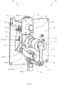
Figure 2 illustrates a perspective view of the interlocking assembly in the switchgear when an electrical device is in OFF position, in accordance with an embodiment of the disclosure. -
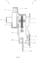
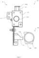
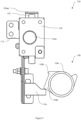
Figure 3 illustrates a side view of the interlocking assembly when an actuator is in a second position, in accordance with an embodiment of the disclosure. -
Figure 4 illustrates a side view of the interlocking assembly when the actuator is in a first position, in accordance with an embodiment of the disclosure. -
Figure 5 illustrates a front view of the interlocking assembly when the electrical device is in OFF position, in accordance with an embodiment of the disclosure. -
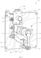
Figure 6 illustrates a perspective view of the interlocking assembly when the electrical device is in GROUND position, in accordance with an embodiment of the disclosure. -
Figure 7 illustrates a front view of the interlocking assembly when the electrical device is in GROUND position, in accordance with an embodiment of the disclosure. -
Figure 8 illustrates a perspective view of the interlocking assembly when the electrical device is in ON position, in accordance with an embodiment of the disclosure. -
Figure 9 illustrates a front view of the interlocking assembly when the electrical device is in ON position, in accordance with an embodiment of the disclosure. - The figures depict embodiments of the disclosure for purposes of illustration only. One skilled in the art will readily recognize from the following description that alternative embodiments of the thermal conductivity detector device illustrated herein may be employed without departing from the principles of the disclosure described herein.
- The foregoing has broadly outlined the features and technical advantages of the present disclosure in order that the description of the disclosure that follows may be better understood. Additional features and advantages of the disclosure will be described hereinafter which form the subject of the disclosure. It should be appreciated by those skilled in the art that the conception and specific embodiments disclosed may be readily utilized as a basis for modifying or designing other systems for carrying out the same purposes of the present disclosure. It should also be realized by those skilled in the art that such equivalent constructions do not depart from the scope of the disclosure. The novel features which are believed to be characteristic of the disclosure, as to its organization, together with further objects and advantages will be better understood from the following description when considered in connection with the accompanying figures. It is to be expressly understood, however, that each of the figures is provided for the purpose of illustration and description only and is not intended as a definition of the limits of the present disclosure.
- While the disclosure is susceptible to various modifications and alternative forms, specific embodiments thereof have been shown by way of example in the drawings and will be described below. It should be understood, however that it is not intended to limit the disclosure to the particular forms disclosed, but on the contrary, the disclosure is to cover all modifications, equivalents, and alternatives falling within the scope of the disclosure.
- The terms "comprises", "comprising", or any other variations thereof used in the disclosure, are intended to cover a non-exclusive inclusion, such that device and system comprises a list of components does not include only those components but may include other components not expressly listed or inherent to such device or system. In other words, one or more elements in device and system proceeded by "comprises" does not, without more constraints, preclude the existence of other elements or additional elements in the system or device.
- The following paragraphs describe the present disclosure with reference to
Figs. 1 to 9 . In the figures, the same element or elements which have similar functions are indicated by the same reference signs. For the purposes of promoting an understanding of the principles of the disclosure, reference will now be made to specific embodiments illustrated in the drawings and specific language will be used to describe the same. It will nevertheless be understood that no limitation of the scope of the disclosure is thereby intended, such alterations and further modifications in the illustrated methods, and such further applications of the principles of the disclosure as illustrated therein being contemplated as would normally occur to one skilled in the art to which the disclosure pertains. - The following detailed description is merely exemplary in nature and is not intended to limit application and uses. Further, there is no intention to be bound by any theory presented in the preceding background or summary or the following detailed description. It is to be understood that the disclosure may assume various alternative orientations and step sequences, except where expressly specified to the contrary. It is also to be understood that the specific devices or components illustrated in the attached drawings and described in the following specification are simply exemplary embodiments of the inventive concepts defined in the appended claims. Hereinafter, preferred embodiments of the present disclosure will be described referring to the accompanying drawings. While some specific terms directed to a specific direction will be used, the purpose of usage of these terms or words is merely to facilitate understanding of the present invention referring to the drawings.
- Accordingly, it should be noted that meaning of these terms or words should not improperly limit the technical scope of the present disclosure. Also, it is to be understood that the phraseology and terminology used herein is for the purpose of description and should not be regarded as limiting. Unless specified or limited otherwise, the terms "mounted," "connected," "supported," and "coupled" and variations thereof are used broadly and encompass both direct and indirect mountings, connections, supports, and couplings. Further, "connected" and "coupled" are not restricted to physical or mechanical connections or couplings. It is to be understood that this disclosure is not limited to the specific devices, methods, applications, conditions, or parameters described and/or shown herein, and that the terminology used herein is for the purpose of describing particular embodiments by way of example and is not intended to be limiting of the claimed invention. In the present document, the word "exemplary" is used herein to mean "serving as an example, instance, or illustration." Any embodiment or implementation of the present subject matter described herein as "exemplary" is not necessarily to be construed as preferred or advantageous over other embodiments.
- In an implementation, the term "electrical safety device" may be a part that is accommodated within a
switchgear 200 including but not limited to a main distribution bus or a busbar, disconnector assemblies, fuses, load break switches and circuit breakers. - Referring to
Figure 1 andFigure 2 , there is disclosed an exemplary embodiment of aswitchgear 200. Theswitchgear 200 may be defined by abody 134 and thebody 134 may include at least one electrical device [herein after referred to as the electrical device] which is switchable between an ON position, an OFF position, and a GROUND position. Theswitchgear 200 may also include one or more protection devices, one or more metering devices and the like. Thebody 134 may be made of metallic materials such as but not limiting to steel, steel alloys and metal composites. In some embodiments, thebody 134 may be made of composite materials such as but not limiting to polymer composites. Thebody 134 of theswitchgear 200 may also accommodate at least one interlocking mechanism 100 [hereinafter referred to as the interlocking mechanism]. Theinterlocking mechanism 100 is coupled to the electrical device. Theinterlocking mechanism 100 may be operable to switch the electrical device between the ON position, the OFF position, and the GROUND position. - The
interlocking mechanism 100 may include asocket 110, which may be configured to receive a tool (not shown in FIGs) for operation of theinterlocking mechanism 100. Further, theinterlocking mechanism 100 may be selectively operated, based on operating condition of the electrical device. That is, operation of theinterlocking mechanism 100 may be restricted when the electrical device is in the GROUND position and operation of theinterlocking mechanism 100 may be allowed when the electrical device is in the ON position and the OFF position. The configuration of theinterlocking mechanism 100 and selective operation of theinterlocking mechanism 100 is described below. - Reference is made from
Figure 2 to Figure 4 . Theinterlocking mechanism 100 may include at least one base plate 124 [hereinafter referred to as the base plate]. Thebase plate 124 may be fixedly coupled to thebody 134 of theswitchgear 200 by any means including but not limited to fasteners. Theinterlocking mechanism 100 may further include abracket 114. Thebracket 114 may be fixedly mounted to thebase plate 124 by any means including but not limited to fasteners. Thebracket 114 may include a section that is fixedly coupled to thebase plate 124 and thebracket 114 may also include a section that extends perpendicularly from thebase plate 124. Further, a plurality of cutouts 128 [hereinafter referred to as the cutouts] may be defined on the section of thebracket 114 that extends perpendicularly from thebase plate 124. Theinterlocking mechanism 100 may include anactuator 102 that is coupled to alock unit 104. Thelock unit 104 may be fixedly mounted to thebase plate 124 through thebracket 114. Further, thelock unit 104 may be mounted to a section of thebracket 114 that extends parallel to thebase plate 124 and the same section may be configured at a predetermined positioned away from thebase plate 124. Thelock unit 104 may include a key 104a. the key 104a of thelock unit 104 may be operable between a first condition and a second condition. Theactuator 102 coupled to thelock unit 104 may be traversed between a first position "A" and a second position "B" when thelock unit 104 is operated between the first condition and the second condition respectively. When the key 104a in thelock unit 104 is rotated or operated to the first condition, theactuator 102 is traversed to the first position "A" as seen fromFigure 4 . Theactuator 102 in the first position "A" may protrude outwardly and may extend away from thelock unit 104. When the key 104a in thelock unit 104 is rotated or operated to the second condition, theactuator 102 is traversed to the second position "B" as seen fromFigure 3 . Theactuator 102 in the second position "B" may also protrude outwardly and may be positioned proximal to thelock unit 104. The height or the distance to which theactuator 102 protrudes outwardly from thelock unit 104 may be lesser in the second position "B" of theactuator 102 when compared to the first position of theactuator 102. - The
interlocking mechanism 100 may further include at least onelink 106. Thelink 106 in this preferable and non-limiting embodiment may be divided into afirst link 106a and asecond link 106b and the same must not be considered as a limitation. Thelink 106 may be a single unitary unit. Thefirst link 106a may be coupled to thebase plate 124 through thebracket 114. Thefirst link 106a may be defined with openings which are of a similar profile as that of thecutouts 128 on thebracket 114. Thefirst link 106a may further be connected to thebracket 114 by any known means including but not limited to a nut andbolt assembly 130. The openings of thefirst link 106a and thecutouts 128 of thebracket 114 may be interconnected together through the nut andbolt assembly 130. Thecutouts 128 on thebracket 114 and the openings of thefirst link 106a are defined with a profile which enables thefirst link 106a to slide or move vertically with respect to the fixedbracket 114. Thefirst link 106a may be defined by a proximal end 106ap and a distal end 106ad. The proximal end 106ap of thefirst link 106a may be configured to contact with theactuator 102. Particularly, the proximal end 106ap of thefirst link 106a may lie in contact with a top end of theactuator 102. Thus, traversing theactuator 102 to the first position "A" by the key 104a may cause theactuator 102 to travel upwardly (seenFigure 4 ) and may also push thefirst link 106a upwardly. Thefirst link 106a may slide along thecutouts 128 and may move upwardly when theactuator 102 is operated to the first position "A". Further, traversing theactuator 102 to the second position "B" by the key 104a may cause theactuator 102 to travel downwardly (seen fromFigure 3 ). Consequently, thefirst link 106a may fall or may travel downwardly along thebracket 114. Thefirst link 106a may slide along thecutouts 128 and may move downwardly when theactuator 102 is operated to the second position "B". Theinterlocking mechanism 100 may also include a biasingmember 132. The biasingmember 132 may be coupled to a nut andbolt assembly 130 at one end and an opposite end of the biasingmember 132 may be coupled to thebracket 114. Particularly, the opposite end of the biasingmember 132 may be coupled to the section of thebracket 114 that lies parallel to the section of thebracket 114 which is in contact with theactuator 102 as seen fromFigure 3 and theFigure 4 . The biasingmember 132 may offer biasing force for traversing thefirst link 106a between the first position "A" and the second position "B". In an implementation, the biasingmember 132 may offer retraction force for traversing thefirst link 106a from first position "A" to the second position "B". Thefirst link 106a in this preferable and non-limiting embodiment may be defined with anarm 116. Thearm 116 may extend transversely from thefirst link 106a and may extend in a direction away from thebracket 114 or towards thelock unit 104. Particularly, thearm 116 may be defined to extend from a region proximal to the distal end 106ad of thefirst link 106. Further, the configuration of thearm 116 must not be considered as a limitation and thearm 116 may also be configured to extend from thesecond link 106b. - The distal end 106ad of the
first link 106a may be coupled to thesecond link 106b. Thesecond link 106b may also be defined by a proximal end 106bp and a distal end 106bd. The proximal end 106bp of thesecond link 106b may be coupled to distal end 106ad of thefirst link 106a. Further, the distal end 106bd of thesecond link 106b may be defined by aslot 122. Since, thesecond link 106b is fixedly coupled to thefirst link 106a, thesecond link 106b and thefirst link 106a may move as a single unit. Traversing theactuator 102 to the first position "A" by the key 104a may cause theactuator 102 to travel upwardly (seenFigure 4 ). Consequently, thefirst link 106a and thesecond link 106b are also pushed upwardly as seen from theFigure 4 andFigure 6 . Further, traversing theactuator 102 to the second position "B" by the key 104a may cause theactuator 102 to travel downwardly (seenFigure 3 ). Consequently, thefirst link 106a and thesecond link 106b are also pushed downwardly as seen from theFigure 3 andFigure 2 . - In an implementation,
interlocking mechanism 100 may include ashaft 118 that is rotatable and is coupled to thebase plate 124. One end of theshaft 118 is coupled to thebase plate 124. Further, ashutter 112 may be configured to an opposite end of theshaft 118. Theshutter 112 may be an elongated member that extends parallel to thebase plate 124. Theshutter 112 may be operable by an operator. Theshutter 112 may be rotated in a clockwise direction or in an anti-clockwise direction. Theshutter 112 may be rotated by the rotation of theshaft 118. Further, theshaft 118 may be configured to lie below the distal end 106bd of thesecond link 106b. Particularly, theshaft 118 may be configured to lie below theslot 122 at the distal end 106bd of thesecond link 106b. Theshaft 118 may further include aconnector 120. Theconnector 120 may be fixedly coupled to theshaft 118 and theconnector 120 may be defined with a "U" shaped profile. Theconnector 120 may be configured to engage with theslot 122 at the distal end 106bd of thesecond link 106b. - The
interlocking mechanism 100 may include thesocket 110. Thesocket 110 may be rotatable and thesocket 110 may be coupled to thebase plate 124. Thesocket 110 may be coupled to the electrical device. In this preferable and non-limiting implementation, thesocket 110 may be rotated by a tool to three different positions. The tool may be inserted into thesocket 110 and thesocket 110 may be rotated in a clockwise direction or an anti-clockwise direction. The rotation of thesocket 110 may cause the electrical device to operate between the ON position, the OFF position, and the GROUND position. Thesocket 110 may be configured to thebase plate 124 at a position that lies proximal to thefirst link 106a and thearm 116 extending from thefirst link 106a. Thesocket 110 may lie adjacent to thearm 116 extending from thefirst link 106a. Further, thesocket 110 may be positioned along the same plane or same vertical axis as that of theshaft 118. Thesocket 110 may be configured to lie directly above theshaft 118. The length of thesocket 110 may be configured to be equal or slightly lesser than that of theshaft 118. Further, theshutter 112 may be configured to partially or completely enclose an opening of thesocket 110 for restricting the insertion of the tool into thesocket 110. - The
interlocking mechanism 100 may further include alocking ring 108 as seen inFigure 5 . Thelocking ring 108 may be defined by a plurality of protrusions (108a, 108b). Particularly, thelocking ring 108 may be defined by afirst protrusion 108a and asecond protrusion 108b. Thelocking ring 108 may also be defined by aflat profile 108c. Thefirst protrusion 108a, thesecond protrusion 108b and theflat profile 108c may be defined along the circumferential region of thelocking ring 108. Further, thelocking ring 108 may be fixedly coupled to thesocket 110. Thelocking ring 108 may be coupled to thesocket 110 at a region where thesocket 110 is coupled to thebase plate 124. Thelocking ring 108 may be coupled to the end of thesocket 110 that is coupled to thebase plate 124. Thelocking ring 108 may be configured to rotate with thesocket 110. Thelocking ring 108 may be configured such that thefirst protrusion 108a, thesecond protrusion 108b and theflat profile 108c engage with thearm 116 from thefirst link 106. - Further, traversing the
actuator 102 to the first position "A" by the key 104a may cause theactuator 102 to travel upwardly (seenFigure 4 ). Therefore, thefirst link 106a and thesecond link 106b are also pushed upwardly as seen from theFigure 4 andFigure 6 . The upward movement of thefirst link 106a and thesecond link 106b causes theslot 122 in thesecond link 106b to engage with theconnector 120 of theshaft 118. Consequently, the rotation of theshaft 118 is prevented and the movement of theshutter 112 coupled to theshaft 118 is also restricted. The above condition where thesecond link 106b engages with theconnector 120 and the condition where the rotation of theshutter 112 is restricted may be defined as a locked position (X) of thelink 106. Further, traversing theactuator 102 to the second position "B" by the key 104a may cause theactuator 102 to travel downwardly (seenFigure 3 ). Consequently, thefirst link 106a and thesecond link 106b are also pushed downwardly as seen from theFigure 3 andFigure 2 . The downward movement of thefirst link 106a and thesecond link 106b causes theslot 122 in thesecond link 106b to disengage with theconnector 120 of theshaft 118. Consequently, the rotation of theshaft 118 is enabled. Theshaft 118 may be traversed in the clockwise direction or in the anti-clockwise direction. Consequently, the movement of theshutter 112 coupled to theshaft 118 is allowed and the tool access to thesocket 110 is enabled. The above condition where thesecond link 106b is disengaged with theconnector 120 and the condition where the rotation of theshutter 112 is allowed may be defined as an un-locked position (Y) of thelink 106. - The working of the
interlocking mechanism 100 is explained in greater detail below. The electrical device may initially be in the OFF position. Thesecond protrusion 108b of thelocking ring 108 may be configured to engage with thearm 116 of thefirst link 106a when the electrical device in in the OFF position as seen fromFigure 2 andFigure 5 . In the electrical device OFF position, the key 104a lies in the second condition and theactuator 102 may lie in the second position "B". Theactuator 102 in the second position "B" remains depressed or is traversed to position of reduced height with respect to thelock unit 104. Consequently, thefirst link 106a and thesecond link 106b are also traversed downwardly such that theslot 122 of thesecond link 106b is disengaged from theconnector 120. Thelink 106 in this scenario may lie in the un-locked position "Y". Consequently, theshaft 118 is allowed to rotate and shutter 112 is also allowed to rotate in the clockwise direction or the anti-clockwise direction. Further, the key 104a of thelock unit 104 remains trapped in thelock unit 104 since rotation of the key 104a from the second condition to the first condition is restricted by thearm 116. Particularly, thearm 116 of thefirst link 106a engages with thesecond protrusion 108b of thelocking ring 108. Consequently, if the operator tries to rotate the key 104a from the second condition to the first condition, thearm 116 of thefirst link 106a collides with thesecond protrusion 108b and the upward movement of thefirst link 106a is prevented. Consequently, the upward movement of the proximal end 106ap of thefirst link 106a is also prevented. Therefore, theactuator 102 that is coupled to thelock unit 104 is also blocked from an upward movement by the proximal end 106ap of thefirst link 106a. Thus, the rotation of the key 104a from the second position to the first position is restricted as the movement of theactuator 102 is blocked by the proximal end 106ap of thefirst link 106a. Therefore, the key 104a remains completely trapped in thelock unit 104 and the key 104a cannot be completely rotated or traversed to the first condition. - Further, if the operator wants to operate the electrical device of the GROUND position, the operator may rotate the
shutter 112 to the clockwise direction or the anti-clockwise direction. Subsequently, a tool may be inserted into thesocket 110 and thesocket 110 may be rotated in the anti-clockwise direction. When thesocket 110 is rotated in the anti-clockwise direction, the electrical device is switched to the GROUND position and all the charges in the electrical device are drained. Further, the rotation of thesocket 110 in the anti-clockwise direction also causes thelocking ring 108 to rotate in the anti-clockwise direction as seen from theFigure 6 andFigure 7 . Thelocking ring 108 rotates along with thesocket 110 such that theflat profile 108c of thelocking ring 108 lies adjacent to thearm 116 of thefirst link 106a. Since theflat profile 108c of thelocking ring 108 does not include any protrusions, thelocking ring 108 does not engage with thearm 116 and there is no contact between the lockingring 108 and thearm 116 of thefirst link 106a. Under this particular scenario, thefirst link 106a and thesecond link 106b are allowed to be traversed upwardly or downwardly with respect to theconnector 120 as there is no constraint between the lockingring 108 and thearm 116 of thefirst link 106a. The user may further rotate the key 104a from the second condition to the first condition. Consequently, theactuator 102 travels from the second position "B" to the first position "A" as seen in theFigure 6 . As theactuator 102 travels to the first position "A", theactuator 102 increases in height with respect to thelock unit 104. The upward movement of theactuator 102 may cause the proximal end 106ap of thefirst link 106a to be pushed upwardly. Consequently, thefirst link 106a and thesecond link 106b are also traversed upwardly with respect to theconnector 120. As thesecond link 106b travels upwardly towards thesocket 110, theslot 122 of thesecond link 106b engages with theconnector 120. This connection between theslot 122 of thesecond link 106b and theconnector 120 locks theshaft 118 and prevents the rotation of theshaft 118 in the clockwise direction or the anti-clockwise direction. The above scenario further defines the locked position "X" of thelink 106 where the rotation of theshaft 118 is restricted. Since the rotation of theshaft 118 is prevented the rotation of theshutter 112 coupled to theshaft 118 is also prevented. Therefore, theshutter 112 lies at the opening of thesocket 110 and theshutter 112 physically prevents the insertion of the tool into thesocket 110. Thus, the rotation of thesocket 110 is prevented and an erroneous switching of electrical device to the ON position or the OFF position from the GROUND position is also prevented. Further, the operator may remove the key 104a from thelock unit 104 as the key 104a is rotated to the second condition. The key 104a may be completely rotated to the second position and due to the completion of the rotation, the key 104a may be removed from thelock unit 104. Once key 104a is removed from thelock unit 104, theactuator 102 remains in the first position "A" and theslot 122 of thesecond link 106b remains engaged with theconnector 120. Therefore, the rotation of theshaft 118 remains restricted and the rotation of theshutter 112 is also prevented. Thus, the operator cannot erroneously rotate theshutter 112 to access or rotate thesocket 110 and erroneously switch the electrical device to the ON position or the OFF position from the GROUND position. Consequently, theswitchgear 200 is rendered to be safe for conducting any maintenance work when the electrical device is in the GROUND position. Erroneous operation of the electrical device to the ON position or the OFF position during the maintenance process of 200 is prevented by the above-describedinterlocking mechanism 100. Further, internal arching faults which may destroy thecomplete switchgear 200, connected lines and load equipment are also prevented. - Once the maintenance work on the
switchgear 200 is concluded, the operator may switch the electrical device to the ON condition from the GROUND condition. The operator may insert the key 104a into thelock unit 104 and the key 104a may be rotated from the second condition to the first condition. The rotation of the key 104a from the first condition to the second condition may cause theactuator 102 to be traversed from the first position "A" to the second position "B" as seen from theFigure 8 and theFigure 9 . As theactuator 102 is pushed downwards, the proximal end 106ap of thefirst link 106a also drops downwardly. Consequently, thesecond link 106b also moves downwardly and theslot 122 of thesecond link 106b is disengaged from theconnector 120. Thus, the rotation of theshaft 118 is allowed and theshutter 112 is allowed to rotate in the clockwise or the anticlockwise direction. Theshutter 112 may now be rotated by the operator to allow access to thesocket 110. The operator may further insert the tool into thesocket 110 and the operator may rotate the tool in the clockwise direction. The rotation of theshaft 118 in the clockwise direction may initially cause the electrical device to be switched to the OFF position. Further, rotation of thesocket 110 in the clockwise direction may cause the electrical device to be switched to the ON position. As thesocket 110 is rotated in the clockwise direction, thelocking ring 108 also rotates in the clockwise direction. Thelocking ring 108 may initially rotate such that thesecond protrusion 108b engages with thearm 116. Further rotation of thesocket 110 in the clockwise direction to switch the electrical device to the ON position may cause thelocking ring 108 to rotate such that thefirst protrusion 108a of thelocking ring 108 engages with thearm 116 of thefirst link 106a. The engaging of thearm 116 with thefirst protrusion 108a traps the key 104a within thelock unit 104. The key 104a of thelock unit 104 remains trapped in thelock unit 104 since rotation of the key 104a from the second condition to the first condition is restricted by thearm 116. Particularly, thearm 116 of thefirst link 106a engages with thefirst protrusion 108a of thelocking ring 108. Consequently, if the operator tries to rotate the key 104a from the second condition to the first condition, thearm 116 of thefirst link 106a collides with thefirst protrusion 108a and the upward movement of thefirst link 106a is prevented. Consequently, the upward movement of the proximal end 106ap of thefirst link 106a is also prevented. Therefore, theactuator 102 that is coupled to thelock unit 104 is also blocked from an upward movement by the proximal end 106ap of thefirst link 106a. Thus, the rotation of the key 104a from the second position to the first position is restricted as the movement of theactuator 102 is blocked by the proximal end 106ap of thefirst link 106a. Therefore, the key 104a remains completely trapped in thelock unit 104 and the key 102a cannot be completely rotated or traversed to the first condition. Theabove interlocking mechanism 100 ensures that the key 104a remains trapped in thelock unit 104 when the electrical device is in the ON position or the OFF position. The key 104a may be removed only when the electrical device is traversed to the GROUND position. In an implementation, the configuration of thelocking ring 108 may be changed such that the key 104a may remain trapped in any of the two positions of the electrical device not being limited to the ON position and the OFF position of the electrical device. In an implementation, the configuration of thelocking ring 108 may be changed such that the key 104a may be removed in any of the positions of the electrical device including but not being limited to the GROUND position of the electrical device. - In an implementation, the above disclosed
interlocking mechanism 100 provides a configuration for conducting maintenance or repair work on theswitchgear 200 in a safe manner. Theinterlocking mechanism 100 prevents the erroneous operation of thesocket 110 when the electrical device is in the GROUND position by restricting access to thesocket 110 and by enabling the removal of the key 104a from thelock unit 104 when the electrical device is in the GROUND position. - With respect to the use of substantially any plural and/or singular terms herein, those having skill in the art can translate from the plural to the singular and/or from the singular to the plural as is appropriate to the context and/or application. The various singular/plural permutations may be expressly set forth herein for sake of clarity.
- It will be understood by those within the art that, in general, terms used herein, and especially in the appended claims e.g., bodies of the appended claims are generally intended as "open" terms e.g., the term "including" should be interpreted as "including but not limited to," the term "having" should be interpreted as "having at least," the term "includes" should be interpreted as "includes but is not limited to," etc.. It will be further understood by those within the art that if a specific number of an introduced claim recitation is intended, such an intent will be explicitly recited in the claim, and in the absence of such recitation no such intent is present. For example, as an aid to understanding, the following appended claims may contain usage of the introductory phrases "at least one" and "one or more" to introduce claim recitations. However, the use of such phrases should not be construed to imply that the introduction of a claim recitation by the indefinite articles "a" or "an" limits any particular claim containing such introduced claim recitation to inventions containing only one such recitation, even when the same claim includes the introductory phrases "one or more" or "at least one" and indefinite articles such as "a" or "an" e.g., "a" and/or "an" should typically be interpreted to mean "at least one" or "one or more"; the same holds true for the use of definite articles used to introduce claim recitations. In addition, even if a specific number of an introduced claim recitation is explicitly recited, those skilled in the art will recognize that such recitation should typically be interpreted to mean atleast the recited number e.g., the bare recitation of "two recitations," without other modifiers, typically means at least two recitations, or two or more recitations. Furthermore, in those instances where a convention analogous to "at least one of A, B, and C, etc." is used, in general such a construction is intended in the sense one having skill in the art would understand the convention e.g., "a system having at least one of A, B, and C" would include but not be limited to systems that have A alone, B alone, C alone, A and B together, A and C together, B and C together, and/or A, B, and C together, etc.. In those instances, where a convention analogous to "at least one of A, B, or C, etc." is used, in general such a construction is intended in the sense one having skill in the art would understand the convention e.g., "a system having at least one of A, B, or C" would include but not be limited to systems that have A alone, B alone, C alone, A and B together, A and C together, B and C together, and/or A, B, and C together, etc.. It will be further understood by those within the art that virtually any disjunctive word and/or phrase presenting two or more alternative terms, whether in the description, claims, or drawings, should be understood to contemplate the possibilities of including one of the terms, either of the terms, or both terms. For example, the phrase "A or B" will be understood to include the possibilities of "A" or "B" or "A and B." While various aspects and embodiments have been disclosed herein, other aspects and embodiments will be apparent to those skilled in the art. The various aspects and embodiments disclosed herein are for purposes of illustration and are not intended to be limiting, with the true scope being indicated by the following claims.
-
Description Referral numerals Interlocking mechanism 100 Actuator 102 Lock unit 104 Key 104a Link 106 First link 106a Proximal end of the first link 106ap Distal end of the first link 106ad Second link 106b Proximal end of the first link 106bp Distal end of the first link 106bd Locking ring 108 First protrusion 108a Second protrusion 108b Flat profile 108c Socket 110 Shutter 112 Bracket 114 Arm 116 Shaft 118 Connector 120 Slot 122 Base plate 124 Cutouts 128 Nut and bolt assembly 130 Biasing member 132 Body 134 Switchgear 200
Claims (10)
- An interlocking mechanism 100 for a switchgear 200, the interlocking mechanism 100 comprising:at least one base plate 124 mounted to the switchgear 200;an actuator 102 coupled to a lock unit 104,
wherein, the lock unit 104 is mounted to the at least one base plate 124, and wherein, the actuator 102 is traversable between a first position A and a second position B based on actuation of the lock unit 104;at least one link 106 mounted on the at least one base plate 124 wherein, one end of the at least one link 106 is in contact with the actuator 102 and is selectively displaced by the actuator 102 between a locked position X and an un-locked position Y;a locking ring 108 coupled with a socket 110,
wherein, the socket 110 is rotatably coupled to the at least one base plate 124, and wherein, the locking ring 108 is defined with a plurality of protrusions 108a, 108b and a flat profile 108c, and a part of the at least one link 106 selectively engages with one of the plurality of protrusions 108a, 108b; anda shutter 112 connected to a shaft 118 defined on the at least one base plate 124, the shaft 118 comprises a connector 120 engageable to the link 106;
wherein, the link 106 in the locked position X lies adjacent to the flat profile 108c of the locking ring 108, engaging with the shutter 112 to restrict the rotation of the shutter 112 and to restrict access to the socket 110. - The interlocking mechanism 100 as claimed in claim 1, wherein the lock unit 104 is operated by a key 104a traversable between a first condition and a second condition.
- The interlocking mechanism 100 as claimed in claim 2, wherein the key 104a traversed to the first condition operates the actuator 102 to the first position A and the key 102a traversed to the second condition operates the actuator 102 to the second position B.
- The interlocking mechanism 100 as claimed in any one of claims 1 through 3, comprising, a bracket 114 mounted to the at least one base plate 124, wherein, the bracket 114 movably accommodates the at least one link 106.
- The interlocking mechanism 100 as claimed in any one of claims 1 through 4, wherein the at least one link 106 comprises:a first link 106a, wherein a proximal end 106ap of the first link 106a is coupled to the actuator 102;a second link 106b wherein, a distal end 106bd of the second link 106b is defined with a slot 122 to receive and engage with the connector 120 and a proximal end 106bp of the second link 106b is coupled to the first link 106a.
- The interlocking mechanism 100 as claimed in any one of claims 1 through 5, further comprising an arm 116 extending from the at least one link 106 wherein, the arm 116 engages with one of the plurality of protrusions 108a, 108b of the locking ring 108.
- The interlocking mechanism 100 as claimed in any one of claims 1 through 6, wherein one end of the shaft 118 is rotatably coupled to the at least one base plate 124 and the opposite end of the shaft 118 is coupled to the shutter 112.
- The interlocking mechanism 100 as claimed in any one of claims 1 through 7, wherein the shaft 118 is positioned adjacent to the socket 110 and extends along a direction parallel to the socket 110.
- The interlocking mechanism 100 as claimed in any one of claims 1 through 8, wherein the connector 120 is transversely coupled to the shaft 118 and the connector 120 selectively engages with the slot 122 to define the locked position X of the at least one link 106.
- A switchgear 200 comprising:at least one electrical device switchable between an ON position, an OFF position and a GROUND position;
an interlocking mechanism 100 coupled to the at least one electrical device, the interlocking mechanism 100 comprising:at least one base plate 124 mounted to the switchgear 200;an actuator 102 coupled to a lock unit 104;wherein, the lock unit 104 is mounted to the at least one base plate 124 and the actuator 102 is traversable between a first position A, andwherein, a second position B based on actuation of the lock unit 104;at least one link 106 mounted on the at least one base plate 124 wherein, one end of the at least one link 106 is in contact with the actuator 102 and is selectively displaced by the actuator 102 between a locked position X and an un-locked position Y;a locking ring 108 coupled with a socket 110,wherein, the socket 110 is rotatably coupled to the at least one base plate 124 to operate the at least one electrical device to one of the ON position, the OFF position and the GROUND position; and,wherein, the locking ring 108 is defined with a plurality of protrusions 108a, 108b and a flat profile 108c and a part of the at least one link 106 selectively engages with one of the plurality of protrusions 108a, 108b; and
a shutter 112 connected to a shaft 118 defined on the at least one base plate 124, the shaft 118 comprises a connector 120 engageable to the link 106;wherein, the link 106 in the locked position X lies adjacent to the flat profile 108c of the locking ring 108, engaging with the shutter 112 to restrict the rotation of the shutter 112 and to restrict access to the socket 110.
Applications Claiming Priority (1)
| Application Number | Priority Date | Filing Date | Title |
|---|---|---|---|
| IN202341003364 | 2023-01-17 |
Publications (2)
| Publication Number | Publication Date |
|---|---|
| EP4404230A1 true EP4404230A1 (en) | 2024-07-24 |
| EP4404230B1 EP4404230B1 (en) | 2025-10-08 |
Family
ID=89620654
Family Applications (1)
| Application Number | Title | Priority Date | Filing Date |
|---|---|---|---|
| EP24152410.7A Active EP4404230B1 (en) | 2023-01-17 | 2024-01-17 | An interlocking mechanism for a switchgear |
Country Status (2)
| Country | Link |
|---|---|
| EP (1) | EP4404230B1 (en) |
| CN (1) | CN118366803A (en) |
Citations (4)
| Publication number | Priority date | Publication date | Assignee | Title |
|---|---|---|---|---|
| CN107527760A (en) * | 2016-06-21 | 2017-12-29 | 浙江正泰电器股份有限公司 | The locking device of breaker |
| CN112786322A (en) * | 2021-01-13 | 2021-05-11 | 乐清市建波电气有限公司 | Electric operating mechanism for circuit breaker |
| CN215265899U (en) * | 2021-07-21 | 2021-12-21 | 巨邦集团有限公司 | A voltage transformer cabinet with emergency power taking |
| CN217881296U (en) * | 2022-06-16 | 2022-11-22 | 万控智造股份有限公司 | Switch hoist and mount ground connection interlocking device |
-
2024
- 2024-01-15 CN CN202410055985.1A patent/CN118366803A/en active Pending
- 2024-01-17 EP EP24152410.7A patent/EP4404230B1/en active Active
Patent Citations (4)
| Publication number | Priority date | Publication date | Assignee | Title |
|---|---|---|---|---|
| CN107527760A (en) * | 2016-06-21 | 2017-12-29 | 浙江正泰电器股份有限公司 | The locking device of breaker |
| CN112786322A (en) * | 2021-01-13 | 2021-05-11 | 乐清市建波电气有限公司 | Electric operating mechanism for circuit breaker |
| CN215265899U (en) * | 2021-07-21 | 2021-12-21 | 巨邦集团有限公司 | A voltage transformer cabinet with emergency power taking |
| CN217881296U (en) * | 2022-06-16 | 2022-11-22 | 万控智造股份有限公司 | Switch hoist and mount ground connection interlocking device |
Also Published As
| Publication number | Publication date |
|---|---|
| CN118366803A (en) | 2024-07-19 |
| EP4404230B1 (en) | 2025-10-08 |
Similar Documents
| Publication | Publication Date | Title |
|---|---|---|
| US6545234B1 (en) | Circuit breaker with mechanical interlock | |
| CN113470996A (en) | Locking hangtag assembly and system and method of use | |
| CN102110545B (en) | Interlock apparatus of ground switch for vacuum circuit breaker | |
| AU2018357310B2 (en) | Locking device for circuit breaker operation device | |
| CN102545084B (en) | Undercarriage and keylock assembly as well as switch device for use with circuit breaker | |
| US6028272A (en) | Lockable position interlock for rackable circuit breakers | |
| EP4209385B1 (en) | Rotary switch body and residual load disconnecting switch | |
| EP3427356B1 (en) | Racking interlocking systems for withdrawable circuit breakers | |
| KR20110128074A (en) | Interlocking device of circuit breaker and switchboard door | |
| US7064283B2 (en) | Device for fixing a power circuit breaker in an insertion rack | |
| EP4404230B1 (en) | An interlocking mechanism for a switchgear | |
| KR102553186B1 (en) | Air Circuit Breaker having Interlock Device | |
| US6864444B2 (en) | Locking device | |
| EP4459649A1 (en) | A switchgear and a safetey assembly for an interlocking mechanism of the switchgear | |
| EP2608233A1 (en) | Electrical load interrupter for low voltage | |
| EP3535771B1 (en) | Power circuit breaker, switching device comprising a power circuit breaker, method for operating a switching device and use of a power circuit breaker | |
| US7091432B2 (en) | Power circuit breaker | |
| CN113302809B (en) | Grounding module for air insulated switchboards | |
| CN205828998U (en) | A locking device and switch cabinet for preventing misoperation of grounding trolley | |
| US11373814B2 (en) | Mechanical interlock for switch | |
| EP1583408B1 (en) | Locking of exchangeable modules with forced automatic disconnection | |
| CN217508080U (en) | Chassis car mechanical interlocking device and switch cabinet | |
| KR102913435B1 (en) | Arc-resistant Switchgear with Enhanced Arc Protection Performance | |
| CN103177888A (en) | Interlocking device | |
| JP2000312408A (en) | Control center bus grounding unit |
Legal Events
| Date | Code | Title | Description |
|---|---|---|---|
| PUAI | Public reference made under article 153(3) epc to a published international application that has entered the european phase |
Free format text: ORIGINAL CODE: 0009012 |
|
| STAA | Information on the status of an ep patent application or granted ep patent |
Free format text: STATUS: REQUEST FOR EXAMINATION WAS MADE |
|
| 17P | Request for examination filed |
Effective date: 20240117 |
|
| AK | Designated contracting states |
Kind code of ref document: A1 Designated state(s): AL AT BE BG CH CY CZ DE DK EE ES FI FR GB GR HR HU IE IS IT LI LT LU LV MC ME MK MT NL NO PL PT RO RS SE SI SK SM TR |
|
| GRAP | Despatch of communication of intention to grant a patent |
Free format text: ORIGINAL CODE: EPIDOSNIGR1 |
|
| STAA | Information on the status of an ep patent application or granted ep patent |
Free format text: STATUS: GRANT OF PATENT IS INTENDED |
|
| INTG | Intention to grant announced |
Effective date: 20250507 |
|
| GRAS | Grant fee paid |
Free format text: ORIGINAL CODE: EPIDOSNIGR3 |
|
| GRAA | (expected) grant |
Free format text: ORIGINAL CODE: 0009210 |
|
| STAA | Information on the status of an ep patent application or granted ep patent |
Free format text: STATUS: THE PATENT HAS BEEN GRANTED |
|
| AK | Designated contracting states |
Kind code of ref document: B1 Designated state(s): AL AT BE BG CH CY CZ DE DK EE ES FI FR GB GR HR HU IE IS IT LI LT LU LV MC ME MK MT NL NO PL PT RO RS SE SI SK SM TR |
|
| REG | Reference to a national code |
Ref country code: GB Ref legal event code: FG4D Ref country code: CH Ref legal event code: F10 Free format text: ST27 STATUS EVENT CODE: U-0-0-F10-F00 (AS PROVIDED BY THE NATIONAL OFFICE) Effective date: 20251008 |
|
| REG | Reference to a national code |
Ref country code: DE Ref legal event code: R096 Ref document number: 602024000812 Country of ref document: DE |
|
| REG | Reference to a national code |
Ref country code: IE Ref legal event code: FG4D |
|
| REG | Reference to a national code |
Ref country code: NL Ref legal event code: MP Effective date: 20251008 |
|
| REG | Reference to a national code |
Ref country code: AT Ref legal event code: MK05 Ref document number: 1845575 Country of ref document: AT Kind code of ref document: T Effective date: 20251008 |
|
| PG25 | Lapsed in a contracting state [announced via postgrant information from national office to epo] |
Ref country code: NL Free format text: LAPSE BECAUSE OF FAILURE TO SUBMIT A TRANSLATION OF THE DESCRIPTION OR TO PAY THE FEE WITHIN THE PRESCRIBED TIME-LIMIT Effective date: 20251008 |
|
| PG25 | Lapsed in a contracting state [announced via postgrant information from national office to epo] |
Ref country code: ES Free format text: LAPSE BECAUSE OF FAILURE TO SUBMIT A TRANSLATION OF THE DESCRIPTION OR TO PAY THE FEE WITHIN THE PRESCRIBED TIME-LIMIT Effective date: 20251008 |
|
| REG | Reference to a national code |
Ref country code: LT Ref legal event code: MG9D |
|
| PG25 | Lapsed in a contracting state [announced via postgrant information from national office to epo] |
Ref country code: NO Free format text: LAPSE BECAUSE OF FAILURE TO SUBMIT A TRANSLATION OF THE DESCRIPTION OR TO PAY THE FEE WITHIN THE PRESCRIBED TIME-LIMIT Effective date: 20260108 |
|
| PGFP | Annual fee paid to national office [announced via postgrant information from national office to epo] |
Ref country code: DE Payment date: 20260121 Year of fee payment: 3 |
|
| PG25 | Lapsed in a contracting state [announced via postgrant information from national office to epo] |
Ref country code: HR Free format text: LAPSE BECAUSE OF FAILURE TO SUBMIT A TRANSLATION OF THE DESCRIPTION OR TO PAY THE FEE WITHIN THE PRESCRIBED TIME-LIMIT Effective date: 20251008 Ref country code: FI Free format text: LAPSE BECAUSE OF FAILURE TO SUBMIT A TRANSLATION OF THE DESCRIPTION OR TO PAY THE FEE WITHIN THE PRESCRIBED TIME-LIMIT Effective date: 20251008 Ref country code: AT Free format text: LAPSE BECAUSE OF FAILURE TO SUBMIT A TRANSLATION OF THE DESCRIPTION OR TO PAY THE FEE WITHIN THE PRESCRIBED TIME-LIMIT Effective date: 20251008 |
|
| PG25 | Lapsed in a contracting state [announced via postgrant information from national office to epo] |
Ref country code: RS Free format text: LAPSE BECAUSE OF FAILURE TO SUBMIT A TRANSLATION OF THE DESCRIPTION OR TO PAY THE FEE WITHIN THE PRESCRIBED TIME-LIMIT Effective date: 20260108 |
|
| PG25 | Lapsed in a contracting state [announced via postgrant information from national office to epo] |
Ref country code: IS Free format text: LAPSE BECAUSE OF FAILURE TO SUBMIT A TRANSLATION OF THE DESCRIPTION OR TO PAY THE FEE WITHIN THE PRESCRIBED TIME-LIMIT Effective date: 20260208 |
|
| PG25 | Lapsed in a contracting state [announced via postgrant information from national office to epo] |
Ref country code: PT Free format text: LAPSE BECAUSE OF FAILURE TO SUBMIT A TRANSLATION OF THE DESCRIPTION OR TO PAY THE FEE WITHIN THE PRESCRIBED TIME-LIMIT Effective date: 20260209 |
|
| PG25 | Lapsed in a contracting state [announced via postgrant information from national office to epo] |
Ref country code: PL Free format text: LAPSE BECAUSE OF FAILURE TO SUBMIT A TRANSLATION OF THE DESCRIPTION OR TO PAY THE FEE WITHIN THE PRESCRIBED TIME-LIMIT Effective date: 20251008 |
|
| PG25 | Lapsed in a contracting state [announced via postgrant information from national office to epo] |
Ref country code: LV Free format text: LAPSE BECAUSE OF FAILURE TO SUBMIT A TRANSLATION OF THE DESCRIPTION OR TO PAY THE FEE WITHIN THE PRESCRIBED TIME-LIMIT Effective date: 20251008 |
|
| PG25 | Lapsed in a contracting state [announced via postgrant information from national office to epo] |
Ref country code: BG Free format text: LAPSE BECAUSE OF FAILURE TO SUBMIT A TRANSLATION OF THE DESCRIPTION OR TO PAY THE FEE WITHIN THE PRESCRIBED TIME-LIMIT Effective date: 20251008 |