EP4404173A1 - Unmanned aerial vehicle for delivering goods using drop zone, operating method thereof and computer readable storage medium - Google Patents
Unmanned aerial vehicle for delivering goods using drop zone, operating method thereof and computer readable storage medium Download PDFInfo
- Publication number
- EP4404173A1 EP4404173A1 EP23199670.3A EP23199670A EP4404173A1 EP 4404173 A1 EP4404173 A1 EP 4404173A1 EP 23199670 A EP23199670 A EP 23199670A EP 4404173 A1 EP4404173 A1 EP 4404173A1
- Authority
- EP
- European Patent Office
- Prior art keywords
- drop
- unmanned aerial
- aerial vehicle
- space
- goods
- Prior art date
- Legal status (The legal status is an assumption and is not a legal conclusion. Google has not performed a legal analysis and makes no representation as to the accuracy of the status listed.)
- Granted
Links
Images




Classifications
-
- B—PERFORMING OPERATIONS; TRANSPORTING
- B64—AIRCRAFT; AVIATION; COSMONAUTICS
- B64D—EQUIPMENT FOR FITTING IN OR TO AIRCRAFT; FLIGHT SUITS; PARACHUTES; ARRANGEMENT OR MOUNTING OF POWER PLANTS OR PROPULSION TRANSMISSIONS IN AIRCRAFT
- B64D1/00—Dropping, ejecting, releasing or receiving articles, liquids, or the like, in flight
- B64D1/02—Dropping, ejecting, or releasing articles
- B64D1/08—Dropping, ejecting, or releasing articles the articles being load-carrying devices
- B64D1/12—Releasing
-
- B—PERFORMING OPERATIONS; TRANSPORTING
- B64—AIRCRAFT; AVIATION; COSMONAUTICS
- B64U—UNMANNED AERIAL VEHICLES [UAV]; EQUIPMENT THEREFOR
- B64U10/00—Type of UAV
- B64U10/10—Rotorcrafts
- B64U10/13—Flying platforms
-
- G—PHYSICS
- G05—CONTROLLING; REGULATING
- G05D—SYSTEMS FOR CONTROLLING OR REGULATING NON-ELECTRIC VARIABLES
- G05D1/00—Control of position, course, altitude or attitude of land, water, air or space vehicles, e.g. using automatic pilots
- G05D1/10—Simultaneous control of position or course in three dimensions
- G05D1/101—Simultaneous control of position or course in three dimensions specially adapted for aircraft
- G05D1/106—Change initiated in response to external conditions, e.g. avoidance of elevated terrain or of no-fly zones
- G05D1/1064—Change initiated in response to external conditions, e.g. avoidance of elevated terrain or of no-fly zones specially adapted for avoiding collisions with other aircraft
-
- A—HUMAN NECESSITIES
- A47—FURNITURE; DOMESTIC ARTICLES OR APPLIANCES; COFFEE MILLS; SPICE MILLS; SUCTION CLEANERS IN GENERAL
- A47G—HOUSEHOLD OR TABLE EQUIPMENT
- A47G29/00—Supports, holders, or containers for household use, not provided for in groups A47G1/00-A47G27/00 or A47G33/00
- A47G29/14—Deposit receptacles for food, e.g. breakfast, milk, or large parcels; Similar receptacles for food or large parcels with appliances for preventing unauthorised removal of the deposited articles, i.e. food or large parcels
-
- B—PERFORMING OPERATIONS; TRANSPORTING
- B64—AIRCRAFT; AVIATION; COSMONAUTICS
- B64C—AEROPLANES; HELICOPTERS
- B64C39/00—Aircraft not otherwise provided for
- B64C39/02—Aircraft not otherwise provided for characterised by special use
- B64C39/024—Aircraft not otherwise provided for characterised by special use of the remote controlled vehicle type, i.e. RPV
-
- B—PERFORMING OPERATIONS; TRANSPORTING
- B64—AIRCRAFT; AVIATION; COSMONAUTICS
- B64F—GROUND OR AIRCRAFT-CARRIER-DECK INSTALLATIONS SPECIALLY ADAPTED FOR USE IN CONNECTION WITH AIRCRAFT; DESIGNING, MANUFACTURING, ASSEMBLING, CLEANING, MAINTAINING OR REPAIRING AIRCRAFT, NOT OTHERWISE PROVIDED FOR; HANDLING, TRANSPORTING, TESTING OR INSPECTING AIRCRAFT COMPONENTS, NOT OTHERWISE PROVIDED FOR
- B64F1/00—Ground or aircraft-carrier-deck installations
-
- B—PERFORMING OPERATIONS; TRANSPORTING
- B64—AIRCRAFT; AVIATION; COSMONAUTICS
- B64U—UNMANNED AERIAL VEHICLES [UAV]; EQUIPMENT THEREFOR
- B64U10/00—Type of UAV
- B64U10/10—Rotorcrafts
- B64U10/13—Flying platforms
- B64U10/14—Flying platforms with four distinct rotor axes, e.g. quadcopters
-
- G—PHYSICS
- G05—CONTROLLING; REGULATING
- G05D—SYSTEMS FOR CONTROLLING OR REGULATING NON-ELECTRIC VARIABLES
- G05D1/00—Control of position, course, altitude or attitude of land, water, air or space vehicles, e.g. using automatic pilots
- G05D1/04—Control of altitude or depth
- G05D1/042—Control of altitude or depth specially adapted for aircraft
-
- G—PHYSICS
- G05—CONTROLLING; REGULATING
- G05D—SYSTEMS FOR CONTROLLING OR REGULATING NON-ELECTRIC VARIABLES
- G05D1/00—Control of position, course, altitude or attitude of land, water, air or space vehicles, e.g. using automatic pilots
- G05D1/40—Control within particular dimensions
- G05D1/46—Control of position or course in three dimensions [3D]
-
- G—PHYSICS
- G05—CONTROLLING; REGULATING
- G05D—SYSTEMS FOR CONTROLLING OR REGULATING NON-ELECTRIC VARIABLES
- G05D1/00—Control of position, course, altitude or attitude of land, water, air or space vehicles, e.g. using automatic pilots
- G05D1/60—Intended control result
- G05D1/69—Coordinated control of the position or course of two or more vehicles
- G05D1/693—Coordinated control of the position or course of two or more vehicles for avoiding collisions between vehicles
-
- G—PHYSICS
- G08—SIGNALLING
- G08G—TRAFFIC CONTROL SYSTEMS
- G08G5/00—Traffic control systems for aircraft
- G08G5/50—Navigation or guidance aids
- G08G5/55—Navigation or guidance aids for a single aircraft
-
- B—PERFORMING OPERATIONS; TRANSPORTING
- B64—AIRCRAFT; AVIATION; COSMONAUTICS
- B64U—UNMANNED AERIAL VEHICLES [UAV]; EQUIPMENT THEREFOR
- B64U2101/00—UAVs specially adapted for particular uses or applications
- B64U2101/60—UAVs specially adapted for particular uses or applications for transporting passengers; for transporting goods other than weapons
-
- B—PERFORMING OPERATIONS; TRANSPORTING
- B64—AIRCRAFT; AVIATION; COSMONAUTICS
- B64U—UNMANNED AERIAL VEHICLES [UAV]; EQUIPMENT THEREFOR
- B64U2101/00—UAVs specially adapted for particular uses or applications
- B64U2101/60—UAVs specially adapted for particular uses or applications for transporting passengers; for transporting goods other than weapons
- B64U2101/64—UAVs specially adapted for particular uses or applications for transporting passengers; for transporting goods other than weapons for parcel delivery or retrieval
-
- B—PERFORMING OPERATIONS; TRANSPORTING
- B64—AIRCRAFT; AVIATION; COSMONAUTICS
- B64U—UNMANNED AERIAL VEHICLES [UAV]; EQUIPMENT THEREFOR
- B64U2101/00—UAVs specially adapted for particular uses or applications
- B64U2101/60—UAVs specially adapted for particular uses or applications for transporting passengers; for transporting goods other than weapons
- B64U2101/69—UAVs specially adapted for particular uses or applications for transporting passengers; for transporting goods other than weapons the UAVs provided with means for airdropping goods, e.g. deploying a parachute during descent
-
- B—PERFORMING OPERATIONS; TRANSPORTING
- B64—AIRCRAFT; AVIATION; COSMONAUTICS
- B64U—UNMANNED AERIAL VEHICLES [UAV]; EQUIPMENT THEREFOR
- B64U2201/00—UAVs characterised by their flight controls
- B64U2201/10—UAVs characterised by their flight controls autonomous, i.e. by navigating independently from ground or air stations, e.g. by using inertial navigation systems [INS]
-
- G—PHYSICS
- G05—CONTROLLING; REGULATING
- G05D—SYSTEMS FOR CONTROLLING OR REGULATING NON-ELECTRIC VARIABLES
- G05D2109/00—Types of controlled vehicles
- G05D2109/20—Aircraft, e.g. drones
-
- G—PHYSICS
- G05—CONTROLLING; REGULATING
- G05D—SYSTEMS FOR CONTROLLING OR REGULATING NON-ELECTRIC VARIABLES
- G05D2109/00—Types of controlled vehicles
- G05D2109/20—Aircraft, e.g. drones
- G05D2109/25—Rotorcrafts
- G05D2109/254—Flying platforms, e.g. multicopters
-
- G—PHYSICS
- G08—SIGNALLING
- G08G—TRAFFIC CONTROL SYSTEMS
- G08G5/00—Traffic control systems for aircraft
- G08G5/50—Navigation or guidance aids
- G08G5/57—Navigation or guidance aids for unmanned aircraft
Definitions
- the present disclosure relates to an unmanned aerial vehicle for delivering goods using a drop box, an operating method thereof, and a computer readable storage medium.
- An aspect of the present disclosure is to provide an unmanned aerial vehicle for delivering goods directly to a high location, such as a rooftop of a high-rise building, and delivering the goods using a drop zone (e.g., a drop box) to prevent collisions between unmanned aerial vehicles, an operating method thereof, and a computer readable storage medium.
- a drop zone e.g., a drop box
- an unmanned aerial vehicle may include: a drive configured to accelerate the unmanned aerial vehicle; a carrying part configured to carry goods; a communication interface; one or more processors; and memory storing instructions that, when executed by the one or more processors, cause the unmanned aerial vehicle to: enter, using the drive, a standby space associated with a drop zone; transmit, based on entering the standby space and via the communication interface, a drop permission request; based on receiving, via the communication interface, a drop permission, enter, using the drive, a drop space above the drop zone; and based on entering the drop space, drop the goods into the drop zone by controlling the carrying part.
- the drop zone may include an upper opening, a lower opening, and an inclined surface connecting the upper opening to the lower opening.
- the drop space may include a space extending, by a first length, upward from the upper opening of the drop zone, and exclude a space directly above the lower opening of the drop zone.
- the standby space may include a space formed by extending, by a second length, from a side surface of the drop space to surround the side surface of the drop space.
- the goods After the goods are dropped to the inclined surface of the drop zone, the goods may be moved to the lower opening by gravity on the inclined surface.
- the inclined surface may have a spiral guide having a preset height formed thereon to reduce a moving speed of the dropped goods.
- the spiral guide may have a curved surface in contact with the goods.
- the standby space may include: a plurality of sub-standby spaces, and a plurality of buffer spaces provided between each of the plurality of the sub-standby spaces to prevent collision between the unmanned aerial vehicle and an adjacent unmanned aerial vehicle.
- the instructions when executed by the one or more processors, may cause the unmanned aerial vehicle to enter the standby space by entering an empty sub-standby space, of the plurality of sub-standby spaces, having a maximum distance from the adjacent unmanned aerial vehicle.
- LEDs Light emitting diodes of different colors may be provided at an edge of the upper opening of the drop zone corresponding to the plurality of sub-standby spaces.
- the instructions when executed by the one or more processors, may cause the unmanned aerial vehicle to, based on completing dropping the goods into the drop zone, exit the drop space by flying up vertically.
- the instructions when executed by the one or more processors, may further cause the unmanned aerial vehicle to transmit, based on completing dropping the goods into the drop zone and via the communication interface, a drop completion notification.
- the instructions when executed by the one or more processors, may further cause the unmanned aerial vehicle to receive, via the communication interface, the drop permission after a previous unmanned aerial vehicle transmits a drop completion notification.
- the instructions when executed by the one or more processors, may further cause the unmanned aerial vehicle to: transmit, before entering the standby space and via the communication interface, an emergency drop request; and, based on receiving the drop permission, enter, using the drive, the drop space without waiting in the standby space.
- the instructions when executed by the one or more processors, may cause the unmanned aerial vehicle to transmit the emergency drop request based on at least one of: a weight of the goods exceeding a threshold weight, a state of charge of a battery associated with the unmanned aerial vehicle being less than a threshold state of charge, or the goods comprising emergency goods.
- the drop zone may include an upper opening, a lower opening, and an inclined surface connecting the upper opening to the lower opening.
- the drop space may include a space formed by extending, by a first length, upward from the upper opening of the drop zone, and exclude a space directly above the lower opening of the drop zone.
- the standby space may include a space formed by extending, by a second length, from a side surface of the drop space to surround the side surface of the drop space.
- the standby space may include: a plurality of sub-standby spaces, and a plurality of buffer spaces provided between each of the plurality of the sub-standby spaces to prevent collisions between the unmanned aerial vehicle and an adjacent unmanned aerial vehicle.
- Entering of the standby space may include entering an empty sub-standby space, of the plurality of sub-standby spaces, having a maximum distance from the adjacent unmanned aerial vehicle.
- the method may further include, based on completing the dropping of the goods, exiting the drop space by flying up vertically.
- the method may further include transmitting, based on completing the dropping of the goods, a drop completion notification.
- the method may further include: transmitting, before the entering of the standby space, an emergency drop request; and based on the receiving of the drop permission, entering the drop space without waiting in the standby space.
- a non-transitory computer-readable storage medium may store instructions that, when executed by one or more processors, cause an unmanned aerial vehicle to: enter a standby space associated with a drop zone; transmit, based on entering the standby space, a drop permission request; based on receiving a drop permission, enter a drop space above the drop zone; and based on entering the drop space, drop goods into the drop zone.
- FIG. 1 is a view illustrating a system for delivering goods using a drop zone.
- a system 100 for delivering goods using a drop zone may include an unmanned aerial vehicle (UAV) 110, a control server 120, and a drop zone (e.g., a drop box) 130.
- UAV unmanned aerial vehicle
- control server 120 e.g., a control server
- drop zone e.g., a drop box
- the unmanned aerial vehicle (UAV) 110 refers to an aerial vehicle configured to fly automatically or semi-automatically according to a preprogrammed path without a pilot directly boarding.
- the unmanned aerial vehicle 110 may fly in a state in which goods G are fixed, and may drop the goods into the drop zone 130 provided on a rooftop of a building 1.
- the control server 120 may manage the delivery of the goods through communication with the unmanned aerial vehicle 110.
- the term "goods” refers to a type of objects that may be mounted in the unmanned aerial vehicle 110 and has a certain volume and weight to deliver a product to a customer.
- the unmanned aerial vehicle 110 the control server 120, and the drop zone 130 will be further described with reference to FIGS. 2 to 5 .
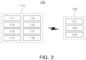
- FIG. 2 is a view illustrating an internal block diagram of an unmanned aerial vehicle and a control server.
- FIG. 3 is a perspective view of a drop zone, a standby space, and a drop space
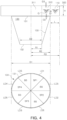
- FIG. 4 is a view illustrating the drop zone, the standby space, and the drop space when viewed from a side surface (see upper portion), and a view illustrating the drop zone when viewed from above (see lower portion).
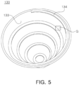
- FIG. 5 is a perspective view illustrating the drop zone.
- the unmanned aerial vehicle 110 may include a drive 111, a carrying part 112, a battery 113, an image sensor 114, a location information acquisition device 115, a controller 116, storage 117, and a communication interface 118.
- the control server 120 may include a controller 121, a communication interface 122, and storage 123.
- the controller 116 and the controller 121 may include a processor (e.g., computer, microprocessor, central processing unit (CPU), application-specific integrated circuit (ASIC), circuitry, logic circuits, etc.) and an associated non-transitory memory storing software instructions which, when executed by the processor, provides the functionalities of the controller 116 and the controller 121 as described here.
- a processor e.g., computer, microprocessor, central processing unit (CPU), application-specific integrated circuit (ASIC), circuitry, logic circuits, etc.
- the memory and the processor may be implemented as separate semiconductor circuits.
- the memory and the processor may be implemented as a single integrated semiconductor circuit.
- the processor may embody one or more processor(s).
- the drive 111 of the unmanned aerial vehicle 110 is a device for moving, propelling, accelerating, and/or controlling a flight of the unmanned aerial vehicle 110 to fly along a preset flight path, and may include, for example, a propeller, a propulsion device, an engine, and/or a driving motor.
- the carrying part 112 (also referred to as a fixing unit, a goods hold, storage, etc.)of the unmanned aerial vehicle 110 may be a device for attaching or mounting goods G to the unmanned aerial vehicle 100, and also for deploying (e.g., dropping, releasing, de-attaching, etc.) the goods G downward by releasing attachment of the goods G under the control of the controller 116 described below.
- the carrying part 112 may be, for example, a clasp, a clamp, a strap, a claw, a hook, an arm, a hatch, a chute, or the like.
- the battery 113 of the unmanned aerial vehicle 110 may be a device for supplying power to each internal components such as the driver 111 and the like, and various types of batteries such as a lithium ion battery and a solid state battery may be used as the battery 113.
- the image sensor 114 of the unmanned aerial vehicle 110 may be a device for capturing a 3D image, and may be, for example, a camera such as a 3D camera.
- the acquired 3D image may be transmitted to the controller 116 described below.
- the location information acquisition device 115 of the unmanned aerial vehicle 110 may be a device for acquiring global positioning system (GPS) information and altitude information of the unmanned aerial vehicle 110, and the acquired GPS information and altitude information may be transmitted to the controller 116 described below.
- GPS global positioning system
- the controller 116 of the unmanned aerial vehicle 110 may control the driver 111 based on the GPS information, the altitude information, and the 3D image as described above.
- the controller 116 may control the driver 111 so that the unmanned aerial vehicle 110 enters the standby space on an upper portion of (e.g., above) the drop zone 130 provided on the rooftop of the building 1, and may control the communication interface 118 to transmit a drop permission request (e.g., a drop permission request message) if the entry into the standby space is completed.
- the drop zone 130 may be an area or space that is designated for reception of goods via gravity-based aerial deployment.
- the drop zone 130 may be a marked or unmarked area, such as a box, a receptacle, a basket, a chute, a rooftop, a porch, a yard, etc.
- the controller 116 may control the driver 111 so that the unmanned aerial vehicle 110 enters the drop space on the upper portion of (e.g., above) the drop zone 130, and may control (e.g., release) the carrying part 112 so that the goods may be dropped into the drop zone 130 if the entry into the drop space is completed.
- drop permission e.g., a drop permission message
- the controller 116 may control the driver 111 so that the unmanned aerial vehicle 110 enters the drop space on the upper portion of (e.g., above) the drop zone 130, and may control (e.g., release) the carrying part 112 so that the goods may be dropped into the drop zone 130 if the entry into the drop space is completed.
- the standby space and the drop space may be set (e.g., designated) in an upper portion 300 of the drop zone 130.
- a drop space 310 may be a space for the unmanned aerial vehicle 110 to drop the goods G into the drop zone 130.
- the drop space 310 may be a space formed by extending upward from (e.g., directly above) the upper opening 131 of the drop zone 130 by a preset length H, and may be a space excluding a space 311 formed by extending upward from (e.g., directly above) a lower opening 132 of the drop zone 130.
- the above-described preset length H may be set to an appropriate length in order to prevent damage to the goods G due to collisions with an inclined surface 133 when dropping the goods G, which may vary depending on a packaging state of the goods G, and a material of the inclined surface. It should be noted that in the present disclosure, the preset length H is not limited to a specific value.
- a waiting space 320 may be a space in which the unmanned aerial vehicle 110 waits for delivery of goods (e.g., prior to moving into the drop space 310 for deployment of the goods).
- the standby space 320 may be a space extending by the preset length L from a side surface of the drop space 310 to surround the side surface of the drop space 310. It should be noted that because the above-described preset length L may vary depending on the size of the unmanned aerial vehicle 110, it is not limited to a specific value in the present disclosure.
- the standby space 320 may be at a higher elevation than the upper opening 131 of the drop zone 130.
- the standby space 320 may be made up of a plurality of sub-standby spaces SP1 to SP4 which the unmanned aerial vehicle 110 enters and a plurality of buffer spaces BS provided between each of the plurality of sub-standby spaces SP1 to SP4 to prevent collisions with adjacent unmanned aerial vehicles.
- the drop zone 130 may be a device for receiving the goods G dropped from the unmanned aerial vehicle 110.
- the drop zone 130 may have a funnel shape including an upper opening 131, a lower opening 132, and an inclined surface 133 having a preset angle formed between the upper opening 131 and the lower opening 132. Because a specific value of an angle of the inclined surface 133 may be appropriately set according to the needs of those skilled in the art, the angle thereof is not limited to a specific value in the present disclosure.
- the angle of the inclined surface 133 may be changed under the control of the control server 120, and to this end, an appropriate means may be provided to adjust the angle.
- a diameter D1 of the upper opening 131 is larger than a diameter D1 of the lower opening 132
- Reference Numeral R1 indicates a radius of the lower opening 132
- Reference Numeral R2 indicates a radius of the upper opening 131
- Reference Numeral R3 indicates a distance from a center 0 of the openings 131 and 132 to an external side of the standby space 320.
- a spiral guide 134 having a preset height to reduce a moving speed of the dropped goods G may be formed on the inclined surface 133 of the drop zone 130. Furthermore, the spiral guide 134 may have a curved surface with which the goods G is in contact, thus moving the goods G within the spiral guide 134 without any separation. The goods G may be dropped to the inclined surface 133 of the drop zone 130 and then moved to the lower opening 132 by gravity on the inclined surface 133.
- LED light emitting diodes
- the LEDs LD1 to LD4 of different colors may be provided at the edge of the upper opening of the drop zone 130 corresponding to a plurality of sub-standby spaces SP1 to SP4.
- an LED LD5 of the same color may be provided at an edge of the upper opening of the drop zone 130 corresponding to the plurality of buffer spaces BS.
- the controller 116 may control the driver 111 so that the unmanned aerial vehicle 110 may enter a sub-standby space without another unmanned aerial vehicle 110 among the plurality of sub-standby spaces SP1 to SP4, but may enter a sub-standby space having a maximum distance from an adjacent unmanned aerial vehicle.
- the controller 116 may control the driver 111 so that the unmanned aerial vehicle 110 may enter a sub-standby space having a maximum distance from the adjacent unmanned aerial vehicle, that is, the third sub-standby space SP3. If another unmanned aerial vehicle exists in the third sub-standby space SP3, the controller 116 may control the driver 111 so that the unmanned aerial vehicle 110 may enter either the second sub-standby space SP2 or the fourth sub-standby space SP4.
- the controller 116 may control the driver 111 so that the unmanned aerial vehicle 110 may fly up vertically to escape (e.g., exit) from the drop space 310.
- the unmanned aerial vehicle 110 waiting in the standby space 320 may enter the drop space 310 by flying horizontally (see part D1), and after the entry is completed, the goods G may be dropped to the inclined surface 133 of the drop zone 130 (see part D2), and then, the unmanned aerial vehicle 110 may fly vertically to escape from the drop space 310(see part D3).
- the controller 116 may control the communication interface 118 to be described below to transmit a drop completion notification to the control server 120.
- the unmanned aerial vehicle in a subsequent order may receive drop permission in the order in which the drop permission request is transmitted.
- the controller 116 may control the communication interface 118 described below to transmit an emergency drop request before the unmanned aerial vehicle 110 enters the standby space 320, and may control the driver 111 so that the unmanned aerial vehicle 110 directly enters the drop space 310 if the drop permission is received in response to the emergency drop request. Then, if the entry into the drop space 310 is completed, the controller 116 may control the carrying part 112 to drop the goods G into the drop zone 130.
- the emergency drop request may be a request including any one of a case in which a weight of the goods G exceeds a preset weight (e.g., a threshold weight), a case in which a remaining capacity (e.g., a state of charge) of the battery 113 is less than a preset remaining capacity (e.g., a threshold state of charge), and a case in which the goods G are emergency goods.
- a preset weight e.g., a threshold weight
- a remaining capacity e.g., a state of charge
- a preset remaining capacity e.g., a threshold state of charge
- the storage 117 of the unmanned aerial vehicle 110 may be a device for storing various programs and/or computer-readable instructions for implementing functions performed by the controller 116 described above.
- the communication interface 118 of the unmanned aerial vehicle 110 may be a device for transmitting or receiving various data to or from the control server 120.
- the communication interface 118 may be capable of communication using, for example, cellular communication (e.g., Global System for Mobile communications (GSM), General Packet Radio Service (GPRS), ***Code Division Multiple Access (CDMA) data channel or data carrying mechanism, an Enhanced Data Rates for GSM Evolution (EDGE) or Enhanced GPRS (EGPRS) data channel, an Evolution-Data Optimized or Evolution-Data only (EV-DO or EVDO) data channel, a Universal Mobile Telecommunications System (UMTS) data channel, any type of Internet Protocol (IP) based wireless protocol, a cellular control channel, etc.
- GSM Global System for Mobile communications
- GPRS General Packet Radio Service
- CDMA Code Division Multiple Access
- CDMA Code Division Multiple Access
- EDGE Enhanced Data Rates for GSM Evolution
- GPRS Enhanced GPRS
- UMTS Universal Mobile Telecommunications System
- controller 121 of the control server 120 manages the delivery of the goods.
- the controller 121 may determine whether a drop completion notification has been received from a previous unmanned aerial vehicle. As a result of the determination, if the drop completion notification is received from the previous unmanned aerial vehicle, the controller 121 determines whether the unmanned aerial vehicle 110 is next in order (e.g., next in queue) for deployment (e.g., dropping goods). As a result of the determination, if the unmanned aerial vehicle 110 is next in order, the drop permission may be transmitted to the unmanned aerial vehicle 110. Then, upon receiving the drop completion notification from the unmanned aerial vehicle 110, drop permission may be transmitted to a next unmanned aerial vehicle.
- the controller 121 receives the emergency drop request from the unmanned aerial vehicle 110, it determines whether the drop completion notification has been received from the previous unmanned aerial vehicle. As a result of the determination, if the drop completion notification is received from the previous unmanned aerial vehicle, the drop permission may be transmitted to the unmanned aerial vehicle 110. Then, upon receiving the drop completion notification from the unmanned aerial vehicle 110, another drop permission may be transmitted to a next unmanned aerial vehicle.
- the storage 123 of the control server 120 may be a device for storing various programs for implementing functions performed by the controller 121 described above. Furthermore, the storage 123 may store the order of the unmanned aerial vehicle in which the drop permission request has been received.
- the upper space of the drop zone provided on the rooftop of the building and receiving the goods may be set as a standby space in which the unmanned aerial vehicle may wait and a drop space in which the goods G may be dropped. If the drop permission is received from the delivery management server, the unmanned aerial vehicle 110 may enter the drop space from the standby space and drop the goods into the drop zone, thereby delivering the goods directly to a high location such as a rooftop of a high-rise building and preventing the collisions between the unmanned aerial vehicles.
- FIG. 6 is a flowchart illustrating a method for delivering goods using a drop zone.
- FIGS. 1 to 5 descriptions overlapping those described in FIGS. 1 to 5 will be omitted.
- a method for delivering goods using a drop zone may be initiated by an operation in which the unmanned aerial vehicle 110 enters the standby space (S601).
- the unmanned aerial vehicle 110 may enter a sub-standby space without another unmanned aerial vehicle among the plurality of sub-standby spaces SP1 to SP4, but may enter a sub-standby space having a maximum distance from an adjacent unmanned aerial vehicle.
- the unmanned aerial vehicle 110 may transmit a drop permission request to the control server 120 (S602).
- the control server 120 Upon receiving the drop permission request, the control server 120 determines whether a drop completion notification has been received from a previous unmanned aerial vehicle (S603). As a result of the determination, if the drop completion notification is received from the previous unmanned aerial vehicle, the control server 120 determines whether the unmanned aerial vehicle 110 is next in order (S604).
- drop permission may be transmitted to the unmanned aerial vehicle 110 (S605).
- the process may return to operation S603.
- the unmanned aerial vehicle 110 receiving the drop permission may enter the drop space on the upper portion of the drop zone 130 (S606), and if the entry into the drop space is completed, the goods may be dropped into the drop zone 130 (S607).
- the unmanned aerial vehicle 110 may vertically fly to escape from the drop space 310 (S609).
- control server 120 receiving the drop completion notification may transmit the drop permission to a next unmanned aerial vehicle (S610).
- the drop space 310 may be a space for the unmanned aerial vehicle 110 to drop the goods G into the drop zone 130.
- the drop space 310 may be a space formed by extending upward from the upper opening 131 of the drop zone 130 by a preset (e.g., predetermined) length H, and may be a space excluding a space 311 formed by extending upward from the lower opening 132 of the drop zone 130.
- the standby space 320 may be a space in which the unmanned aerial vehicle 110 waits for delivery of goods.
- the standby space 320 may be a space extending by a present length L from a side surface of the drop space 310 to surround the side surface of the drop space 310.
- the standby space 320 may be made up of the plurality of sub-standby spaces SP1 to SP4 which unmanned aerial vehicle 110 enters and the plurality of buffer spaces BS provided between each of the plurality of sub-standby spaces SP1 to SP4 to prevent the collisions with the adjacent unmanned aerial vehicles.
- the drop zone 130 may be a device for receiving the goods G dropped from the unmanned aerial vehicle 110.
- the drop zone 130 may have the funnel shape including the upper opening 131, the lower opening 132, and the inclined surface 133 having a preset angle formed between the upper opening 131 and the lower opening 132.
- FIG. 7 is a flowchart illustrating a method for delivering goods using a drop zone, which belongs to a case in which an emergency drop request occurs.
- a method for delivering goods using a drop zone may be initiated by an operation in which the unmanned aerial vehicle 110 transmits an emergency drop request to the control server 120 (S701).
- the control server 120 receiving the emergency drop request may determine whether a drop completion notification has been received from the previous unmanned aerial vehicle (S702).
- the control server 120 may transmit drop permission to the unmanned aerial vehicle 110 (S703).
- the unmanned aerial vehicle 110 receiving the drop permission may enter the drop space on the upper portion of the drop zone 130 (S704), and if the entry into the drop space is completed, the goods may be dropped into the drop zone 130 (S705).
- the unmanned aerial vehicle 110 may vertically fly to escape from the drop space 310 (S707).
- control server 120 receiving the drop completion notification may transmit the drop permission to a next unmanned aerial vehicle (S708).
- the upper space of the drop zone provided on the rooftop of the building and receiving the goods may be set as a standby space in which the unmanned aerial vehicle may wait and a drop space in which the goods may be dropped.
- the unmanned aerial vehicle 110 may enter the drop space from the standby space and drop the goods into the drop zone, thereby delivering the goods directly to the high location such as the rooftop of the high-rise building and preventing the collisions between the unmanned aerial vehicles.
- FIG. 8 is a block diagram of a computer device configured to entirely or partially implement an unmanned aerial vehicle or a control server, which may be applied to the unmanned aerial vehicle 110 and the control server 120 illustrated in FIG. 2 .
- a computer device 800 includes an input interface 801, an output interface 802, a processor 804, a memory 805, and a communication interface 806, and the input interface 801, the output interface 802, the processor 804, the memory 805, and the communication interface 806 may be connected to each other through a bus 803.
- the memory 805 may be used to store a program, a command, or a code, and the processor 804 may perform the program, the command, or the code stored in the memory 805, may control the input interface 801 to receive a signal, and may control the output interface 802 to transmit the signal.
- the memory 805 may include a read-only memory (ROM) and a random access memory (RAM), and may provide commands and data to the processor 804.
- the processor 804 may be a central processing unit (CPU), and should be understood as being another general-purpose processor (DSP), a digital signal processor (DSP), an application specific integrated circuit (ASIC), a field programmable gate array (FPGA) or other programmable logic devices, an individual gate or transistor logic devices, and individual hardware components.
- the general-purpose processor may be a microprocessor, or the corresponding processor may be any conventional processor.
- a method performed in each device of FIG. 2 may be achieved by an integrated logic circuit of hardware or a software type command in the processor 804.
- the content of the method disclosed in relation to one or more example embodiments of the present disclosure may be implemented and completed by a hardware processor or may be implemented and completed by a combination of hardware and software modules of the processor.
- the software module may be placed in storage media such as a random access memory, a flash memory, a read-only memory, a programmable read-only memory, or an electrically erasable programmable memory, a registers, etc.
- the storage medium is disposed in the memory 805, and the processor 804 reads information from the memory 805 and combines the information with hardware to implement the content of the above-described method. To avoid duplication, a detailed description thereof will be omitted.
- unit may be implemented in various ways, such as a processor, program commands executed by the processor, a software module, a micro code, a computer program product, a logic circuit, an application-only integrated circuit, a firmware, etc., or may be implemented by hardware.
Landscapes
- Engineering & Computer Science (AREA)
- Aviation & Aerospace Engineering (AREA)
- Remote Sensing (AREA)
- Physics & Mathematics (AREA)
- General Physics & Mathematics (AREA)
- Radar, Positioning & Navigation (AREA)
- Automation & Control Theory (AREA)
- Mechanical Engineering (AREA)
- Food Science & Technology (AREA)
- Control Of Position, Course, Altitude, Or Attitude Of Moving Bodies (AREA)
- Traffic Control Systems (AREA)
- Microelectronics & Electronic Packaging (AREA)
Abstract
Description
- This application claims benefit of priority to
Korean Patent Application No. 10-2023-0008956, filed on January 20, 2023 - The present disclosure relates to an unmanned aerial vehicle for delivering goods using a drop box, an operating method thereof, and a computer readable storage medium.
- Recently, research and development of the delivery of goods using unmanned aerial vehicles such as drones have been conducted. There is a need for the development of a system for delivering goods directly to an elevated location such as the rooftop of a high-rise building using such unmanned aerial vehicles. Furthermore, in the instant case, it is necessary to prevent collisions among unmanned aerial vehicles that deliver the goods.
- An aspect of the present disclosure is to provide an unmanned aerial vehicle for delivering goods directly to a high location, such as a rooftop of a high-rise building, and delivering the goods using a drop zone (e.g., a drop box) to prevent collisions between unmanned aerial vehicles, an operating method thereof, and a computer readable storage medium.
- According to one or more embodiments of the present disclosure, an unmanned aerial vehicle may include: a drive configured to accelerate the unmanned aerial vehicle; a carrying part configured to carry goods; a communication interface; one or more processors; and memory storing instructions that, when executed by the one or more processors, cause the unmanned aerial vehicle to: enter, using the drive, a standby space associated with a drop zone; transmit, based on entering the standby space and via the communication interface, a drop permission request; based on receiving, via the communication interface, a drop permission, enter, using the drive, a drop space above the drop zone; and based on entering the drop space, drop the goods into the drop zone by controlling the carrying part.
- The drop zone may include an upper opening, a lower opening, and an inclined surface connecting the upper opening to the lower opening. The drop space may include a space extending, by a first length, upward from the upper opening of the drop zone, and exclude a space directly above the lower opening of the drop zone. The standby space may include a space formed by extending, by a second length, from a side surface of the drop space to surround the side surface of the drop space.
- After the goods are dropped to the inclined surface of the drop zone, the goods may be moved to the lower opening by gravity on the inclined surface.
- The inclined surface may have a spiral guide having a preset height formed thereon to reduce a moving speed of the dropped goods. The spiral guide may have a curved surface in contact with the goods.
- The standby space may include: a plurality of sub-standby spaces, and a plurality of buffer spaces provided between each of the plurality of the sub-standby spaces to prevent collision between the unmanned aerial vehicle and an adjacent unmanned aerial vehicle.
- The instructions, when executed by the one or more processors, may cause the unmanned aerial vehicle to enter the standby space by entering an empty sub-standby space, of the plurality of sub-standby spaces, having a maximum distance from the adjacent unmanned aerial vehicle.
- Light emitting diodes (LEDs) of different colors may be provided at an edge of the upper opening of the drop zone corresponding to the plurality of sub-standby spaces.
- The instructions, when executed by the one or more processors, may cause the unmanned aerial vehicle to, based on completing dropping the goods into the drop zone, exit the drop space by flying up vertically.
- The instructions, when executed by the one or more processors, may further cause the unmanned aerial vehicle to transmit, based on completing dropping the goods into the drop zone and via the communication interface, a drop completion notification.
- The instructions, when executed by the one or more processors, may further cause the unmanned aerial vehicle to receive, via the communication interface, the drop permission after a previous unmanned aerial vehicle transmits a drop completion notification.
- The instructions, when executed by the one or more processors, may further cause the unmanned aerial vehicle to: transmit, before entering the standby space and via the communication interface, an emergency drop request; and, based on receiving the drop permission, enter, using the drive, the drop space without waiting in the standby space.
- The instructions, when executed by the one or more processors, may cause the unmanned aerial vehicle to transmit the emergency drop request based on at least one of: a weight of the goods exceeding a threshold weight, a state of charge of a battery associated with the unmanned aerial vehicle being less than a threshold state of charge, or the goods comprising emergency goods.
- According to one or more embodiments of the present disclosure, a method may include: entering, by an unmanned aerial vehicle, a standby space associated with a drop zone; transmitting, based on entering the standby space, a drop permission request; based on receiving a drop permission, entering a drop space above the drop zone; and based on entering the drop space, dropping goods into the drop zone.
- The drop zone may include an upper opening, a lower opening, and an inclined surface connecting the upper opening to the lower opening. The drop space may include a space formed by extending, by a first length, upward from the upper opening of the drop zone, and exclude a space directly above the lower opening of the drop zone. The standby space may include a space formed by extending, by a second length, from a side surface of the drop space to surround the side surface of the drop space.
- The standby space may include: a plurality of sub-standby spaces, and a plurality of buffer spaces provided between each of the plurality of the sub-standby spaces to prevent collisions between the unmanned aerial vehicle and an adjacent unmanned aerial vehicle.
- Entering of the standby space may include entering an empty sub-standby space, of the plurality of sub-standby spaces, having a maximum distance from the adjacent unmanned aerial vehicle.
- The method may further include, based on completing the dropping of the goods, exiting the drop space by flying up vertically.
- The method may further include transmitting, based on completing the dropping of the goods, a drop completion notification.
- The method may further include: transmitting, before the entering of the standby space, an emergency drop request; and based on the receiving of the drop permission, entering the drop space without waiting in the standby space.
- According to one or more embodiments of the present disclosure, a non-transitory computer-readable storage medium may store instructions that, when executed by one or more processors, cause an unmanned aerial vehicle to: enter a standby space associated with a drop zone; transmit, based on entering the standby space, a drop permission request; based on receiving a drop permission, enter a drop space above the drop zone; and based on entering the drop space, drop goods into the drop zone.
- The above and other aspects, features, and advantages of the present disclosure will be more clearly understood from the following detailed description, taken in conjunction with the accompanying drawings, in which:
-
FIG. 1 is a view illustrating a system for delivering goods using a drop zone; -
FIG. 2 is a view illustrating an internal block diagram of an unmanned aerial vehicle and a control server; -
FIG. 3 is a perspective view of a drop zone, a standby space, and a drop space; -
FIG. 4 is a view illustrating the drop zone, the standby space, and the drop space when viewed from a side surface (see upper portion), and a view illustrating the drop zone when viewed from above (see lower portion); -
FIG. 5 is a perspective view illustrating the drop zone; -
FIG. 6 is a flowchart illustrating a method for delivering goods using a drop zone; -
FIG. 7 is a flowchart illustrating a method for delivering goods using a drop zone, which belongs to a case in which an emergency drop request occurs; and -
FIG. 8 is a block diagram of a computer device configured to entirely or partially implement an unmanned aerial vehicle or a control server. - Hereinafter, the present disclosure will be described with reference to specific example embodiments and the attached drawings. The embodiments of the present disclosure may, however, be exemplified in many different forms and should not be construed as being limited to the specific embodiments set forth herein. The example embodiments disclosed herein are provided for those skilled in the art to better explain the present disclosure. In the drawings, the shapes and dimensions of elements may be exaggerated for clarity, and the same reference numerals will be used throughout to designate the same or like elements.
-
FIG. 1 is a view illustrating a system for delivering goods using a drop zone. - As illustrated in
FIG. 1 , asystem 100 for delivering goods using a drop zone may include an unmanned aerial vehicle (UAV) 110, acontrol server 120, and a drop zone (e.g., a drop box) 130. - In the present disclosure, the unmanned aerial vehicle (UAV) 110 refers to an aerial vehicle configured to fly automatically or semi-automatically according to a preprogrammed path without a pilot directly boarding. The unmanned
aerial vehicle 110 may fly in a state in which goods G are fixed, and may drop the goods into thedrop zone 130 provided on a rooftop of abuilding 1. Meanwhile, thecontrol server 120 may manage the delivery of the goods through communication with the unmannedaerial vehicle 110. - Furthermore, in the present disclosure, the term "goods" refers to a type of objects that may be mounted in the unmanned
aerial vehicle 110 and has a certain volume and weight to deliver a product to a customer. - Hereinafter, the unmanned
aerial vehicle 110, thecontrol server 120, and thedrop zone 130 will be further described with reference toFIGS. 2 to 5 . -
FIG. 2 is a view illustrating an internal block diagram of an unmanned aerial vehicle and a control server. Meanwhile,FIG. 3 is a perspective view of a drop zone, a standby space, and a drop space, andFIG. 4 is a view illustrating the drop zone, the standby space, and the drop space when viewed from a side surface (see upper portion), and a view illustrating the drop zone when viewed from above (see lower portion). Furthermore,FIG. 5 is a perspective view illustrating the drop zone. - As illustrated in
FIG. 2 , the unmannedaerial vehicle 110 may include adrive 111, a carryingpart 112, abattery 113, animage sensor 114, a locationinformation acquisition device 115, acontroller 116,storage 117, and acommunication interface 118. Furthermore, thecontrol server 120 may include acontroller 121, acommunication interface 122, andstorage 123. - The
controller 116 and thecontroller 121 may include a processor (e.g., computer, microprocessor, central processing unit (CPU), application-specific integrated circuit (ASIC), circuitry, logic circuits, etc.) and an associated non-transitory memory storing software instructions which, when executed by the processor, provides the functionalities of thecontroller 116 and thecontroller 121 as described here. Herein, the memory and the processor may be implemented as separate semiconductor circuits. Alternatively, the memory and the processor may be implemented as a single integrated semiconductor circuit. The processor may embody one or more processor(s). - Specifically, the
drive 111 of the unmannedaerial vehicle 110 is a device for moving, propelling, accelerating, and/or controlling a flight of the unmannedaerial vehicle 110 to fly along a preset flight path, and may include, for example, a propeller, a propulsion device, an engine, and/or a driving motor. - The carrying part 112 (also referred to as a fixing unit, a goods hold, storage, etc.)of the unmanned
aerial vehicle 110 may be a device for attaching or mounting goods G to the unmannedaerial vehicle 100, and also for deploying (e.g., dropping, releasing, de-attaching, etc.) the goods G downward by releasing attachment of the goods G under the control of thecontroller 116 described below. The carryingpart 112 may be, for example, a clasp, a clamp, a strap, a claw, a hook, an arm, a hatch, a chute, or the like. - The
battery 113 of the unmannedaerial vehicle 110 may be a device for supplying power to each internal components such as thedriver 111 and the like, and various types of batteries such as a lithium ion battery and a solid state battery may be used as thebattery 113. - The
image sensor 114 of the unmannedaerial vehicle 110 may be a device for capturing a 3D image, and may be, for example, a camera such as a 3D camera. The acquired 3D image may be transmitted to thecontroller 116 described below. - The location
information acquisition device 115 of the unmannedaerial vehicle 110 may be a device for acquiring global positioning system (GPS) information and altitude information of the unmannedaerial vehicle 110, and the acquired GPS information and altitude information may be transmitted to thecontroller 116 described below. - The
controller 116 of the unmannedaerial vehicle 110 may control thedriver 111 based on the GPS information, the altitude information, and the 3D image as described above. - Specifically, the
controller 116 may control thedriver 111 so that the unmannedaerial vehicle 110 enters the standby space on an upper portion of (e.g., above) thedrop zone 130 provided on the rooftop of thebuilding 1, and may control thecommunication interface 118 to transmit a drop permission request (e.g., a drop permission request message) if the entry into the standby space is completed. Thedrop zone 130 may be an area or space that is designated for reception of goods via gravity-based aerial deployment. For example, thedrop zone 130 may be a marked or unmarked area, such as a box, a receptacle, a basket, a chute, a rooftop, a porch, a yard, etc. - Furthermore, if drop permission (e.g., a drop permission message) is received in response to the drop permission request, the
controller 116 may control thedriver 111 so that the unmannedaerial vehicle 110 enters the drop space on the upper portion of (e.g., above) thedrop zone 130, and may control (e.g., release) the carryingpart 112 so that the goods may be dropped into thedrop zone 130 if the entry into the drop space is completed. - Hereinafter, with reference to
FIGS. 3 to 5 , the standby space, the drop space, and the drop zone will be described. - The standby space and the drop space may be set (e.g., designated) in an
upper portion 300 of thedrop zone 130. - Here, a
drop space 310 may be a space for the unmannedaerial vehicle 110 to drop the goods G into thedrop zone 130. Specifically, thedrop space 310 may be a space formed by extending upward from (e.g., directly above) theupper opening 131 of thedrop zone 130 by a preset length H, and may be a space excluding aspace 311 formed by extending upward from (e.g., directly above) alower opening 132 of thedrop zone 130. The above-described preset length H may be set to an appropriate length in order to prevent damage to the goods G due to collisions with aninclined surface 133 when dropping the goods G, which may vary depending on a packaging state of the goods G, and a material of the inclined surface. It should be noted that in the present disclosure, the preset length H is not limited to a specific value. - A waiting space 320 (also referred to as a "waiting space") may be a space in which the unmanned
aerial vehicle 110 waits for delivery of goods (e.g., prior to moving into thedrop space 310 for deployment of the goods). Specifically, thestandby space 320 may be a space extending by the preset length L from a side surface of thedrop space 310 to surround the side surface of thedrop space 310. It should be noted that because the above-described preset length L may vary depending on the size of the unmannedaerial vehicle 110, it is not limited to a specific value in the present disclosure. Thestandby space 320 may be at a higher elevation than theupper opening 131 of thedrop zone 130. - Furthermore, the
standby space 320 may be made up of a plurality of sub-standby spaces SP1 to SP4 which the unmannedaerial vehicle 110 enters and a plurality of buffer spaces BS provided between each of the plurality of sub-standby spaces SP1 to SP4 to prevent collisions with adjacent unmanned aerial vehicles. - Meanwhile, the
drop zone 130 may be a device for receiving the goods G dropped from the unmannedaerial vehicle 110. Specifically, thedrop zone 130 may have a funnel shape including anupper opening 131, alower opening 132, and aninclined surface 133 having a preset angle formed between theupper opening 131 and thelower opening 132. Because a specific value of an angle of theinclined surface 133 may be appropriately set according to the needs of those skilled in the art, the angle thereof is not limited to a specific value in the present disclosure. Furthermore, the angle of theinclined surface 133 may be changed under the control of thecontrol server 120, and to this end, an appropriate means may be provided to adjust the angle. - As illustrated in
FIG. 4 , a diameter D1 of theupper opening 131 is larger than a diameter D1 of thelower opening 132, and Reference Numeral R1 indicates a radius of thelower opening 132, Reference Numeral R2 indicates a radius of theupper opening 131, and Reference Numeral R3 indicates a distance from a center 0 of theopenings standby space 320. - Furthermore, as illustrated in
FIG. 5 , aspiral guide 134 having a preset height to reduce a moving speed of the dropped goods G may be formed on theinclined surface 133 of thedrop zone 130. Furthermore, thespiral guide 134 may have a curved surface with which the goods G is in contact, thus moving the goods G within thespiral guide 134 without any separation. The goods G may be dropped to theinclined surface 133 of thedrop zone 130 and then moved to thelower opening 132 by gravity on theinclined surface 133. - Furthermore, as illustrated in lower portion of
FIG. 4 , light emitting diodes (LED) LD1 to LD5 may be provided at an edge of theupper opening 131 of thedrop zone 130. Specifically, the LEDs LD1 to LD4 of different colors may be provided at the edge of the upper opening of thedrop zone 130 corresponding to a plurality of sub-standby spaces SP1 to SP4. Furthermore, an LED LD5 of the same color may be provided at an edge of the upper opening of thedrop zone 130 corresponding to the plurality of buffer spaces BS. - Meanwhile, the
controller 116 may control thedriver 111 so that the unmannedaerial vehicle 110 may enter a sub-standby space without another unmannedaerial vehicle 110 among the plurality of sub-standby spaces SP1 to SP4, but may enter a sub-standby space having a maximum distance from an adjacent unmanned aerial vehicle. - For example, as illustrated in the lower portion of
FIG. 4 , if there is an unmanned aerial vehicle waiting in the first sub-standby space SP1 among the plurality of sub-standby spaces SP1 to SP4, thecontroller 116 may control thedriver 111 so that the unmannedaerial vehicle 110 may enter a sub-standby space having a maximum distance from the adjacent unmanned aerial vehicle, that is, the third sub-standby space SP3. If another unmanned aerial vehicle exists in the third sub-standby space SP3, thecontroller 116 may control thedriver 111 so that the unmannedaerial vehicle 110 may enter either the second sub-standby space SP2 or the fourth sub-standby space SP4. - Furthermore, if the drop of the goods G is completed, the
controller 116 may control thedriver 111 so that the unmannedaerial vehicle 110 may fly up vertically to escape (e.g., exit) from thedrop space 310. - For example, as illustrated in upper portion of
FIG. 4 , the unmannedaerial vehicle 110 waiting in thestandby space 320 may enter thedrop space 310 by flying horizontally (see part D1), and after the entry is completed, the goods G may be dropped to theinclined surface 133 of the drop zone 130 (see part D2), and then, the unmannedaerial vehicle 110 may fly vertically to escape from the drop space 310(see part D3). - Furthermore, if the drop of the goods G is completed, the
controller 116 may control thecommunication interface 118 to be described below to transmit a drop completion notification to thecontrol server 120. After the drop completion notification is transmitted, the unmanned aerial vehicle in a subsequent order may receive drop permission in the order in which the drop permission request is transmitted. - Meanwhile, the
controller 116 may control thecommunication interface 118 described below to transmit an emergency drop request before the unmannedaerial vehicle 110 enters thestandby space 320, and may control thedriver 111 so that the unmannedaerial vehicle 110 directly enters thedrop space 310 if the drop permission is received in response to the emergency drop request. Then, if the entry into thedrop space 310 is completed, thecontroller 116 may control the carryingpart 112 to drop the goods G into thedrop zone 130. - For example, the emergency drop request may be a request including any one of a case in which a weight of the goods G exceeds a preset weight (e.g., a threshold weight), a case in which a remaining capacity (e.g., a state of charge) of the
battery 113 is less than a preset remaining capacity (e.g., a threshold state of charge), and a case in which the goods G are emergency goods. - The
storage 117 of the unmannedaerial vehicle 110 may be a device for storing various programs and/or computer-readable instructions for implementing functions performed by thecontroller 116 described above. - The
communication interface 118 of the unmannedaerial vehicle 110 may be a device for transmitting or receiving various data to or from thecontrol server 120. Thecommunication interface 118 may be capable of communication using, for example, cellular communication (e.g., Global System for Mobile communications (GSM), General Packet Radio Service (GPRS), ***Code Division Multiple Access (CDMA) data channel or data carrying mechanism, an Enhanced Data Rates for GSM Evolution (EDGE) or Enhanced GPRS (EGPRS) data channel, an Evolution-Data Optimized or Evolution-Data only (EV-DO or EVDO) data channel, a Universal Mobile Telecommunications System (UMTS) data channel, any type of Internet Protocol (IP) based wireless protocol, a cellular control channel, etc. - Meanwhile, the
controller 121 of thecontrol server 120 manages the delivery of the goods. - Specifically, when receiving the drop permission request from the unmanned
aerial vehicle 110, thecontroller 121 may determine whether a drop completion notification has been received from a previous unmanned aerial vehicle. As a result of the determination, if the drop completion notification is received from the previous unmanned aerial vehicle, thecontroller 121 determines whether the unmannedaerial vehicle 110 is next in order (e.g., next in queue) for deployment (e.g., dropping goods). As a result of the determination, if the unmannedaerial vehicle 110 is next in order, the drop permission may be transmitted to the unmannedaerial vehicle 110. Then, upon receiving the drop completion notification from the unmannedaerial vehicle 110, drop permission may be transmitted to a next unmanned aerial vehicle. - Furthermore, if the
controller 121 receives the emergency drop request from the unmannedaerial vehicle 110, it determines whether the drop completion notification has been received from the previous unmanned aerial vehicle. As a result of the determination, if the drop completion notification is received from the previous unmanned aerial vehicle, the drop permission may be transmitted to the unmannedaerial vehicle 110. Then, upon receiving the drop completion notification from the unmannedaerial vehicle 110, another drop permission may be transmitted to a next unmanned aerial vehicle. - Meanwhile, the
communication interface 122 of thecontrol server 120 may be a device for transmitting or receiving various data to or from the unmannedaerial vehicle 110. - In addition, the
storage 123 of thecontrol server 120 may be a device for storing various programs for implementing functions performed by thecontroller 121 described above. Furthermore, thestorage 123 may store the order of the unmanned aerial vehicle in which the drop permission request has been received. - As described above, the upper space of the drop zone provided on the rooftop of the building and receiving the goods may be set as a standby space in which the unmanned aerial vehicle may wait and a drop space in which the goods G may be dropped. If the drop permission is received from the delivery management server, the unmanned
aerial vehicle 110 may enter the drop space from the standby space and drop the goods into the drop zone, thereby delivering the goods directly to a high location such as a rooftop of a high-rise building and preventing the collisions between the unmanned aerial vehicles. - Hereinafter,
FIG. 6 is a flowchart illustrating a method for delivering goods using a drop zone. For simplification of the invention, descriptions overlapping those described inFIGS. 1 to 5 will be omitted. - Referring to
FIGS. 1 to 6 , a method for delivering goods using a drop zone (S600) may be initiated by an operation in which the unmannedaerial vehicle 110 enters the standby space (S601). - The unmanned
aerial vehicle 110 may enter a sub-standby space without another unmanned aerial vehicle among the plurality of sub-standby spaces SP1 to SP4, but may enter a sub-standby space having a maximum distance from an adjacent unmanned aerial vehicle. - If the entry into the standby space is completed, the unmanned
aerial vehicle 110 may transmit a drop permission request to the control server 120 (S602). - Upon receiving the drop permission request, the
control server 120 determines whether a drop completion notification has been received from a previous unmanned aerial vehicle (S603). As a result of the determination, if the drop completion notification is received from the previous unmanned aerial vehicle, thecontrol server 120 determines whether the unmannedaerial vehicle 110 is next in order (S604). - As a result of the determination, if the unmanned
aerial vehicle 110 is next in order, drop permission may be transmitted to the unmanned aerial vehicle 110 (S605). On the other hand, as a result of the determination, if the unmannedaerial vehicle 110 is not next in order, the process may return to operation S603. - Then, the unmanned
aerial vehicle 110 receiving the drop permission may enter the drop space on the upper portion of the drop zone 130 (S606), and if the entry into the drop space is completed, the goods may be dropped into the drop zone 130 (S607). - Then, after transmitting the drop completion notification to the control server 120 (S608), the unmanned
aerial vehicle 110 may vertically fly to escape from the drop space 310 (S609). - Meanwhile, the
control server 120 receiving the drop completion notification may transmit the drop permission to a next unmanned aerial vehicle (S610). - The
drop space 310 may be a space for the unmannedaerial vehicle 110 to drop the goods G into thedrop zone 130. Specifically, as described above, thedrop space 310 may be a space formed by extending upward from theupper opening 131 of thedrop zone 130 by a preset (e.g., predetermined) length H, and may be a space excluding aspace 311 formed by extending upward from thelower opening 132 of thedrop zone 130. - Furthermore, the
standby space 320 may be a space in which the unmannedaerial vehicle 110 waits for delivery of goods. Specifically, as described above, thestandby space 320 may be a space extending by a present length L from a side surface of thedrop space 310 to surround the side surface of thedrop space 310. - Furthermore, as described above, the
standby space 320 may be made up of the plurality of sub-standby spaces SP1 to SP4 which unmannedaerial vehicle 110 enters and the plurality of buffer spaces BS provided between each of the plurality of sub-standby spaces SP1 to SP4 to prevent the collisions with the adjacent unmanned aerial vehicles. - Furthermore, the
drop zone 130 may be a device for receiving the goods G dropped from the unmannedaerial vehicle 110. Specifically, as described above, thedrop zone 130 may have the funnel shape including theupper opening 131, thelower opening 132, and theinclined surface 133 having a preset angle formed between theupper opening 131 and thelower opening 132. - Meanwhile,
FIG. 7 is a flowchart illustrating a method for delivering goods using a drop zone, which belongs to a case in which an emergency drop request occurs. - Referring to
FIGS. 1 to 5 and7 , a method for delivering goods using a drop zone (S600) may be initiated by an operation in which the unmannedaerial vehicle 110 transmits an emergency drop request to the control server 120 (S701). - The
control server 120 receiving the emergency drop request may determine whether a drop completion notification has been received from the previous unmanned aerial vehicle (S702). - As a result of the determination, if the drop completion notification is received from the previous unmanned aerial vehicle, the
control server 120 may transmit drop permission to the unmanned aerial vehicle 110 (S703). - Then, the unmanned
aerial vehicle 110 receiving the drop permission may enter the drop space on the upper portion of the drop zone 130 (S704), and if the entry into the drop space is completed, the goods may be dropped into the drop zone 130 (S705). - Then, after transmitting the drop completion notification to the control server 120 (S706), the unmanned
aerial vehicle 110 may vertically fly to escape from the drop space 310 (S707). - Meanwhile, the
control server 120 receiving the drop completion notification may transmit the drop permission to a next unmanned aerial vehicle (S708). - As described above, the upper space of the drop zone provided on the rooftop of the building and receiving the goods may be set as a standby space in which the unmanned aerial vehicle may wait and a drop space in which the goods may be dropped. if the drop permission is received from the delivery management server, the unmanned
aerial vehicle 110 may enter the drop space from the standby space and drop the goods into the drop zone, thereby delivering the goods directly to the high location such as the rooftop of the high-rise building and preventing the collisions between the unmanned aerial vehicles. - Meanwhile,
FIG. 8 is a block diagram of a computer device configured to entirely or partially implement an unmanned aerial vehicle or a control server, which may be applied to the unmannedaerial vehicle 110 and thecontrol server 120 illustrated inFIG. 2 . - As illustrated in
FIG. 8 , acomputer device 800 includes aninput interface 801, anoutput interface 802, aprocessor 804, amemory 805, and acommunication interface 806, and theinput interface 801, theoutput interface 802, theprocessor 804, thememory 805, and thecommunication interface 806 may be connected to each other through abus 803. - The
memory 805 may be used to store a program, a command, or a code, and theprocessor 804 may perform the program, the command, or the code stored in thememory 805, may control theinput interface 801 to receive a signal, and may control theoutput interface 802 to transmit the signal. Thememory 805 may include a read-only memory (ROM) and a random access memory (RAM), and may provide commands and data to theprocessor 804. - The
processor 804 may be a central processing unit (CPU), and should be understood as being another general-purpose processor (DSP), a digital signal processor (DSP), an application specific integrated circuit (ASIC), a field programmable gate array (FPGA) or other programmable logic devices, an individual gate or transistor logic devices, and individual hardware components. The general-purpose processor may be a microprocessor, or the corresponding processor may be any conventional processor. - In an implementation process, a method performed in each device of
FIG. 2 may be achieved by an integrated logic circuit of hardware or a software type command in theprocessor 804. The content of the method disclosed in relation to one or more example embodiments of the present disclosure may be implemented and completed by a hardware processor or may be implemented and completed by a combination of hardware and software modules of the processor. The software module may be placed in storage media such as a random access memory, a flash memory, a read-only memory, a programmable read-only memory, or an electrically erasable programmable memory, a registers, etc. The storage medium is disposed in thememory 805, and theprocessor 804 reads information from thememory 805 and combines the information with hardware to implement the content of the above-described method. To avoid duplication, a detailed description thereof will be omitted. - Meanwhile, in the present disclosure, "unit" may be implemented in various ways, such as a processor, program commands executed by the processor, a software module, a micro code, a computer program product, a logic circuit, an application-only integrated circuit, a firmware, etc., or may be implemented by hardware.
- The present disclosure is not limited to the example embodiments described above and the accompanying drawings. The scope of rights of the present disclosure is intended to be limited by the appended claims. It will be understood by those skilled in the art that various substitutions, modification and changes in form and details may be made therein without departing from the spirit and scope of the present disclosure as defined by the appended claims.
Claims (15)
- An unmanned aerial vehicle comprising:a drive configured to accelerate the unmanned aerial vehicle;a carrying part configured to carry goods;a communication interface;one or more processors; andmemory storing instructions that, when executed by the one or more processors, cause the unmanned aerial vehicle to:enter, using the drive, a standby space associated with a drop zone;transmit, based on entering the standby space and via the communication interface, a drop permission request;based on receiving, via the communication interface, a drop permission, enter, using the drive, a drop space above the drop zone; andbased on entering the drop space, drop the goods into the drop zone by controlling the carrying part.
- The unmanned aerial vehicle of claim 1, wherein the drop zone comprises an upper opening, a lower opening, and an inclined surface connecting the upper opening to the lower opening,wherein the drop space comprises a space extending, by a first length, upward from the upper opening of the drop zone, and excludes a space directly above the lower opening of the drop zone, andwherein the standby space comprises a space formed by extending, by a second length, from a side surface of the drop space to surround the side surface of the drop space.
- The unmanned aerial vehicle of claim 2, wherein after the goods are dropped to the inclined surface of the drop zone, the goods are moved to the lower opening by gravity on the inclined surface.
- The unmanned aerial vehicle of claim 2 or 3, wherein the inclined surface has a spiral guide having a preset height formed thereon to reduce a moving speed of the dropped goods,
wherein the spiral guide has a curved surface in contact with the goods. - The unmanned aerial vehicle of one of claims 1-4, wherein the standby space comprises:a plurality of sub-standby spaces, anda plurality of buffer spaces provided between each of the plurality of the sub-standby spaces to prevent collision between the unmanned aerial vehicle and an adjacent unmanned aerial vehicle.
- The unmanned aerial vehicle of claim 5, wherein the instructions, when executed by the one or more processors, cause the unmanned aerial vehicle to enter the standby space by entering an empty sub-standby space, of the plurality of sub-standby spaces, having a maximum distance from the adjacent unmanned aerial vehicle.
- The unmanned aerial vehicle of claim 5 or 6, wherein light emitting diodes (LEDs) of different colors are provided at an edge of the upper opening of the drop zone corresponding to the plurality of sub-standby spaces.
- The unmanned aerial vehicle of one of claims 1-7, wherein the instructions, when executed by the one or more processors, cause the unmanned aerial vehicle to, based on completing dropping the goods into the drop zone, exit the drop space by flying up vertically.
- The unmanned aerial vehicle of one of claims 1-8, wherein the instructions, when executed by the one or more processors, further cause the unmanned aerial vehicle to transmit, based on completing dropping the goods into the drop zone and via the communication interface, a drop completion notification.
- The unmanned aerial vehicle of one of claims 1-9, wherein the instructions, when executed by the one or more processors, further cause the unmanned aerial vehicle to receive, via the communication interface, the drop permission after a previous unmanned aerial vehicle transmits a drop completion notification.
- The unmanned aerial vehicle of one of claims 1-10, wherein the instructions that, when executed by the one or more processors, further cause the unmanned aerial vehicle to:transmit, before entering the standby space and via the communication interface, an emergency drop request; andbased on receiving the drop permission, enter, using the drive, the drop space without waiting in the standby space.
- The unmanned aerial vehicle of claim 11, wherein the instructions that, when executed by the one or more processors, cause the unmanned aerial vehicle to transmit the emergency drop request based on at least one of:a weight of the goods exceeding a threshold weight,a state of charge of a battery associated with the unmanned aerial vehicle being less than a threshold state of charge, orthe goods comprising emergency goods.
- A method comprising:entering, by an unmanned aerial vehicle, a standby space associated with a drop zone;transmitting, based on entering the standby space, a drop permission request;based on receiving a drop permission, entering a drop space above the drop zone; andbased on entering the drop space, dropping goods into the drop zone.
- The method of claim 13, wherein the drop zone comprises an upper opening, a lower opening, and an inclined surface connecting the upper opening to the lower opening,wherein the drop space comprises a space formed by extending, by a first length, upward from the upper opening of the drop zone, and excludes a space directly above the lower opening of the drop zone, andwherein the standby space comprises a space formed by extending, by a second length, from a side surface of the drop space to surround the side surface of the drop space.
- The method of claim 13 or 14, wherein the standby space comprises:a plurality of sub-standby spaces, anda plurality of buffer spaces provided between each of the plurality of the sub-standby spaces to prevent collisions between the unmanned aerial vehicle and an adjacent unmanned aerial vehicle.
Applications Claiming Priority (1)
| Application Number | Priority Date | Filing Date | Title |
|---|---|---|---|
| KR1020230008956A KR20240116259A (en) | 2023-01-20 | 2023-01-20 | Unmanned aerial vehicle for delivering goods using dropbox, operating method thereof and computer readable storage medium |
Publications (2)
| Publication Number | Publication Date |
|---|---|
| EP4404173A1 true EP4404173A1 (en) | 2024-07-24 |
| EP4404173B1 EP4404173B1 (en) | 2026-02-18 |
Family
ID=88197076
Family Applications (1)
| Application Number | Title | Priority Date | Filing Date |
|---|---|---|---|
| EP23199670.3A Active EP4404173B1 (en) | 2023-01-20 | 2023-09-26 | Unmanned aerial vehicle for delivering goods using drop zone, operating method thereof and computer readable storage medium |
Country Status (4)
| Country | Link |
|---|---|
| US (1) | US12510902B2 (en) |
| EP (1) | EP4404173B1 (en) |
| KR (1) | KR20240116259A (en) |
| CN (1) | CN118372975A (en) |
Families Citing this family (1)
| Publication number | Priority date | Publication date | Assignee | Title |
|---|---|---|---|---|
| US12557930B2 (en) * | 2022-07-01 | 2026-02-24 | James Lawrence Eastman | Drone delivery systems and methods |
Citations (5)
| Publication number | Priority date | Publication date | Assignee | Title |
|---|---|---|---|---|
| US20160185466A1 (en) * | 2014-12-30 | 2016-06-30 | Frank Dreano, JR. | System and method for enhancing distribution logistics and increasing surveillance ranges with unmanned aerial vehicles and a dock network |
| US9387928B1 (en) * | 2014-12-18 | 2016-07-12 | Amazon Technologies, Inc. | Multi-use UAV docking station systems and methods |
| US20170032315A1 (en) * | 2014-04-13 | 2017-02-02 | Vishal Gupta | Aerial parcel delivery |
| WO2018199460A1 (en) * | 2017-04-25 | 2018-11-01 | Cj Logistics Corporation | Unmanned transport system using unmanned aerial vehicle |
| US20190130770A1 (en) * | 2017-10-27 | 2019-05-02 | Drone Delivery Canada Corp. | Unmanned aerial vehicle delivery system for delivery of medical or emergency supplies |
Family Cites Families (16)
| Publication number | Priority date | Publication date | Assignee | Title |
|---|---|---|---|---|
| US9359074B2 (en) * | 2014-09-08 | 2016-06-07 | Qualcomm Incorporated | Methods, systems and devices for delivery drone security |
| WO2016037219A1 (en) | 2014-09-10 | 2016-03-17 | Burchat Clinton Graeme | Delivery system |
| WO2018000026A1 (en) * | 2016-06-28 | 2018-01-04 | Burchat Clinton Graeme | Extendible collection apparatus |
| US9975651B1 (en) * | 2017-01-26 | 2018-05-22 | Brandon Eck | Transfer station for transferring containers between unmanned aerial vehicles and unmanned ground vehicle |
| CN107451788A (en) | 2017-09-09 | 2017-12-08 | 厦门大壮深飞科技有限公司 | Automatic delivering method and delivery station are concentrated in unmanned plane logistics based on independent navigation |
| US10647508B2 (en) * | 2017-11-22 | 2020-05-12 | Brandon Eck | Storage station for storing containers transported by unmanned vehicles |
| US20190302249A1 (en) * | 2018-03-29 | 2019-10-03 | Walmart Apollo, Llc | System and method for drone position determination |
| US11213156B2 (en) | 2018-07-17 | 2022-01-04 | Greg Morris Photographer Llc | Drone package drop adapter |
| AU2018256468B1 (en) * | 2018-07-24 | 2019-12-05 | Clinton Graeme BURCHAT | Directed delivery system |
| US10946982B2 (en) * | 2018-12-19 | 2021-03-16 | Ford Global Technologies, Llc | Systems and methods for roof-top UAV delivery |
| KR102455360B1 (en) | 2020-08-24 | 2022-10-14 | 구자균 | Drone delivery station |
| KR102228277B1 (en) | 2020-09-14 | 2021-03-18 | 주식회사 일도엔지니어링 | System for selling goods using drones |
| JP7609411B2 (en) | 2021-01-25 | 2025-01-07 | Necソリューションイノベータ株式会社 | Delivery support device, delivery support method, and program |
| US12304657B2 (en) * | 2021-06-02 | 2025-05-20 | Textron Innovations Inc. | Unmanned aerial system kiosk |
| WO2023095924A1 (en) * | 2021-11-29 | 2023-06-01 | パナソニック インテレクチュアル プロパティ コーポレーション オブ アメリカ | System |
| US12205072B1 (en) * | 2022-09-13 | 2025-01-21 | Amazon Technologies, Inc. | Fulfilling orders for multiple items from multiple sources via multimodal channels |
-
2023
- 2023-01-20 KR KR1020230008956A patent/KR20240116259A/en active Pending
- 2023-07-11 US US18/220,486 patent/US12510902B2/en active Active
- 2023-07-25 CN CN202310922161.5A patent/CN118372975A/en active Pending
- 2023-09-26 EP EP23199670.3A patent/EP4404173B1/en active Active
Patent Citations (5)
| Publication number | Priority date | Publication date | Assignee | Title |
|---|---|---|---|---|
| US20170032315A1 (en) * | 2014-04-13 | 2017-02-02 | Vishal Gupta | Aerial parcel delivery |
| US9387928B1 (en) * | 2014-12-18 | 2016-07-12 | Amazon Technologies, Inc. | Multi-use UAV docking station systems and methods |
| US20160185466A1 (en) * | 2014-12-30 | 2016-06-30 | Frank Dreano, JR. | System and method for enhancing distribution logistics and increasing surveillance ranges with unmanned aerial vehicles and a dock network |
| WO2018199460A1 (en) * | 2017-04-25 | 2018-11-01 | Cj Logistics Corporation | Unmanned transport system using unmanned aerial vehicle |
| US20190130770A1 (en) * | 2017-10-27 | 2019-05-02 | Drone Delivery Canada Corp. | Unmanned aerial vehicle delivery system for delivery of medical or emergency supplies |
Also Published As
| Publication number | Publication date |
|---|---|
| CN118372975A (en) | 2024-07-23 |
| US20240248476A1 (en) | 2024-07-25 |
| EP4404173B1 (en) | 2026-02-18 |
| KR20240116259A (en) | 2024-07-29 |
| US12510902B2 (en) | 2025-12-30 |
Similar Documents
| Publication | Publication Date | Title |
|---|---|---|
| US11514390B2 (en) | Delivery system and processing server | |
| US11347219B2 (en) | Trailer for autonomous delivery | |
| US10948910B2 (en) | Robotic vehicle separated payload detection and response | |
| US11210956B2 (en) | Method for directing an unmanned aerial vehicle to a destination | |
| JP7057020B2 (en) | How to transport an air vehicle and luggage using it | |
| JP6881344B2 (en) | Pick-up system | |
| CN108473209B (en) | A control method, equipment, unmanned aerial vehicle, charging base station and system | |
| EP4404173B1 (en) | Unmanned aerial vehicle for delivering goods using drop zone, operating method thereof and computer readable storage medium | |
| KR102321351B1 (en) | Integrated control system for drone | |
| US11210137B2 (en) | Controlling devices | |
| KR102355885B1 (en) | Drone station and drone take-off system comprising thereof | |
| JP6760704B2 (en) | Power supply system for unmanned aerial vehicles | |
| US12277863B2 (en) | Information processing apparatus, information processing method, program, and information processing system | |
| CN207424683U (en) | Unmanned plane launching and recovering equipment and system | |
| WO2021027969A1 (en) | Control method and apparatus for movable device, electronic device, and storage medium | |
| CN109995117A (en) | Charging system and method based on robot | |
| JP2024111617A (en) | Airborne power supply system | |
| JPWO2019146516A1 (en) | Flight control device and flight control system | |
| US20240338042A1 (en) | Transport system | |
| JP7164899B1 (en) | Baggage management system | |
| JP6717557B1 (en) | Power supply system for unmanned air vehicles | |
| JP6674570B1 (en) | Power supply system for unmanned aerial vehicles | |
| CN213813956U (en) | Intelligent interface and safety protection device for unmanned aerial vehicle mounted laser radar system during medium and long voyage | |
| US20240010337A1 (en) | Detachable, self-balancing, multi-payload delivery pod for uav | |
| JP2023113301A (en) | Goods delivery system and goods delivery method |
Legal Events
| Date | Code | Title | Description |
|---|---|---|---|
| PUAI | Public reference made under article 153(3) epc to a published international application that has entered the european phase |
Free format text: ORIGINAL CODE: 0009012 |
|
| STAA | Information on the status of an ep patent application or granted ep patent |
Free format text: STATUS: THE APPLICATION HAS BEEN PUBLISHED |
|
| AK | Designated contracting states |
Kind code of ref document: A1 Designated state(s): AL AT BE BG CH CY CZ DE DK EE ES FI FR GB GR HR HU IE IS IT LI LT LU LV MC ME MK MT NL NO PL PT RO RS SE SI SK SM TR |
|
| STAA | Information on the status of an ep patent application or granted ep patent |
Free format text: STATUS: REQUEST FOR EXAMINATION WAS MADE |
|
| 17P | Request for examination filed |
Effective date: 20240823 |
|
| RBV | Designated contracting states (corrected) |
Designated state(s): AL AT BE BG CH CY CZ DE DK EE ES FI FR GB GR HR HU IE IS IT LI LT LU LV MC ME MK MT NL NO PL PT RO RS SE SI SK SM TR |
|
| STAA | Information on the status of an ep patent application or granted ep patent |
Free format text: STATUS: EXAMINATION IS IN PROGRESS |
|
| P01 | Opt-out of the competence of the unified patent court (upc) registered |
Free format text: CASE NUMBER: APP_7532/2025 Effective date: 20250213 |
|
| 17Q | First examination report despatched |
Effective date: 20250324 |
|
| RIC1 | Information provided on ipc code assigned before grant |
Ipc: G08G 5/00 20060101AFI20250728BHEP Ipc: B64C 39/02 20230101ALI20250728BHEP Ipc: B64F 1/32 20060101ALI20250728BHEP Ipc: B64U 101/60 20230101ALI20250728BHEP Ipc: B64D 1/12 20060101ALI20250728BHEP Ipc: B64U 101/64 20230101ALI20250728BHEP Ipc: G08G 5/55 20250101ALI20250728BHEP Ipc: B64U 10/13 20230101ALI20250728BHEP |
|
| GRAP | Despatch of communication of intention to grant a patent |
Free format text: ORIGINAL CODE: EPIDOSNIGR1 |
|
| STAA | Information on the status of an ep patent application or granted ep patent |
Free format text: STATUS: GRANT OF PATENT IS INTENDED |
|
| INTG | Intention to grant announced |
Effective date: 20250912 |
|
| GRAS | Grant fee paid |
Free format text: ORIGINAL CODE: EPIDOSNIGR3 |
|
| GRAA | (expected) grant |
Free format text: ORIGINAL CODE: 0009210 |
|
| STAA | Information on the status of an ep patent application or granted ep patent |
Free format text: STATUS: THE PATENT HAS BEEN GRANTED |
|
| AK | Designated contracting states |
Kind code of ref document: B1 Designated state(s): AL AT BE BG CH CY CZ DE DK EE ES FI FR GB GR HR HU IE IS IT LI LT LU LV MC ME MK MT NL NO PL PT RO RS SE SI SK SM TR |
|
| REG | Reference to a national code |
Ref country code: CH Ref legal event code: F10 Free format text: ST27 STATUS EVENT CODE: U-0-0-F10-F00 (AS PROVIDED BY THE NATIONAL OFFICE) Effective date: 20260218 Ref country code: GB Ref legal event code: FG4D |
|
| REG | Reference to a national code |
Ref country code: IE Ref legal event code: FG4D |
|
| REG | Reference to a national code |
Ref country code: DE Ref legal event code: R096 Ref document number: 602023012138 Country of ref document: DE |
|
| REG | Reference to a national code |
Ref country code: NL Ref legal event code: MP Effective date: 20260218 |
|
| PG25 | Lapsed in a contracting state [announced via postgrant information from national office to epo] |
Ref country code: RS Free format text: LAPSE BECAUSE OF FAILURE TO SUBMIT A TRANSLATION OF THE DESCRIPTION OR TO PAY THE FEE WITHIN THE PRESCRIBED TIME-LIMIT Effective date: 20260518 |
|
| PG25 | Lapsed in a contracting state [announced via postgrant information from national office to epo] |
Ref country code: ES Free format text: LAPSE BECAUSE OF FAILURE TO SUBMIT A TRANSLATION OF THE DESCRIPTION OR TO PAY THE FEE WITHIN THE PRESCRIBED TIME-LIMIT Effective date: 20260218 |
|
| PG25 | Lapsed in a contracting state [announced via postgrant information from national office to epo] |
Ref country code: PL Free format text: LAPSE BECAUSE OF FAILURE TO SUBMIT A TRANSLATION OF THE DESCRIPTION OR TO PAY THE FEE WITHIN THE PRESCRIBED TIME-LIMIT Effective date: 20260218 |
|
| PG25 | Lapsed in a contracting state [announced via postgrant information from national office to epo] |
Ref country code: GR Free format text: LAPSE BECAUSE OF FAILURE TO SUBMIT A TRANSLATION OF THE DESCRIPTION OR TO PAY THE FEE WITHIN THE PRESCRIBED TIME-LIMIT Effective date: 20260519 |
|
| REG | Reference to a national code |
Ref country code: LT Ref legal event code: MG9D |
|
| PG25 | Lapsed in a contracting state [announced via postgrant information from national office to epo] |
Ref country code: LT Free format text: LAPSE BECAUSE OF FAILURE TO SUBMIT A TRANSLATION OF THE DESCRIPTION OR TO PAY THE FEE WITHIN THE PRESCRIBED TIME-LIMIT Effective date: 20260218 |
|
| PG25 | Lapsed in a contracting state [announced via postgrant information from national office to epo] |
Ref country code: NO Free format text: LAPSE BECAUSE OF FAILURE TO SUBMIT A TRANSLATION OF THE DESCRIPTION OR TO PAY THE FEE WITHIN THE PRESCRIBED TIME-LIMIT Effective date: 20260518 |
|
| PG25 | Lapsed in a contracting state [announced via postgrant information from national office to epo] |
Ref country code: SE Free format text: LAPSE BECAUSE OF FAILURE TO SUBMIT A TRANSLATION OF THE DESCRIPTION OR TO PAY THE FEE WITHIN THE PRESCRIBED TIME-LIMIT Effective date: 20260218 Ref country code: FI Free format text: LAPSE BECAUSE OF FAILURE TO SUBMIT A TRANSLATION OF THE DESCRIPTION OR TO PAY THE FEE WITHIN THE PRESCRIBED TIME-LIMIT Effective date: 20260218 Ref country code: AT Free format text: LAPSE BECAUSE OF FAILURE TO SUBMIT A TRANSLATION OF THE DESCRIPTION OR TO PAY THE FEE WITHIN THE PRESCRIBED TIME-LIMIT Effective date: 20260218 |
|
| REG | Reference to a national code |
Ref country code: AT Ref legal event code: MK05 Ref document number: 1889068 Country of ref document: AT Kind code of ref document: T Effective date: 20260218 |
|
| PG25 | Lapsed in a contracting state [announced via postgrant information from national office to epo] |
Ref country code: HR Free format text: LAPSE BECAUSE OF FAILURE TO SUBMIT A TRANSLATION OF THE DESCRIPTION OR TO PAY THE FEE WITHIN THE PRESCRIBED TIME-LIMIT Effective date: 20260218 |
|
| PG25 | Lapsed in a contracting state [announced via postgrant information from national office to epo] |
Ref country code: PT Free format text: LAPSE BECAUSE OF FAILURE TO SUBMIT A TRANSLATION OF THE DESCRIPTION OR TO PAY THE FEE WITHIN THE PRESCRIBED TIME-LIMIT Effective date: 20260618 Ref country code: IS Free format text: LAPSE BECAUSE OF FAILURE TO SUBMIT A TRANSLATION OF THE DESCRIPTION OR TO PAY THE FEE WITHIN THE PRESCRIBED TIME-LIMIT Effective date: 20260618 |
|
| PG25 | Lapsed in a contracting state [announced via postgrant information from national office to epo] |
Ref country code: NL Free format text: LAPSE BECAUSE OF FAILURE TO SUBMIT A TRANSLATION OF THE DESCRIPTION OR TO PAY THE FEE WITHIN THE PRESCRIBED TIME-LIMIT Effective date: 20260218 |
|
| PG25 | Lapsed in a contracting state [announced via postgrant information from national office to epo] |
Ref country code: LV Free format text: LAPSE BECAUSE OF FAILURE TO SUBMIT A TRANSLATION OF THE DESCRIPTION OR TO PAY THE FEE WITHIN THE PRESCRIBED TIME-LIMIT Effective date: 20260218 |
|
| PG25 | Lapsed in a contracting state [announced via postgrant information from national office to epo] |
Ref country code: BG Free format text: LAPSE BECAUSE OF FAILURE TO SUBMIT A TRANSLATION OF THE DESCRIPTION OR TO PAY THE FEE WITHIN THE PRESCRIBED TIME-LIMIT Effective date: 20260218 |