EP4404147A1 - System and method for training a machine learning model - Google Patents
System and method for training a machine learning model Download PDFInfo
- Publication number
- EP4404147A1 EP4404147A1 EP23217684.2A EP23217684A EP4404147A1 EP 4404147 A1 EP4404147 A1 EP 4404147A1 EP 23217684 A EP23217684 A EP 23217684A EP 4404147 A1 EP4404147 A1 EP 4404147A1
- Authority
- EP
- European Patent Office
- Prior art keywords
- clusters
- images
- data elements
- feature
- data
- Prior art date
- Legal status (The legal status is an assumption and is not a legal conclusion. Google has not performed a legal analysis and makes no representation as to the accuracy of the status listed.)
- Pending
Links
Images



Classifications
-
- G—PHYSICS
- G06—COMPUTING OR CALCULATING; COUNTING
- G06V—IMAGE OR VIDEO RECOGNITION OR UNDERSTANDING
- G06V10/00—Arrangements for image or video recognition or understanding
- G06V10/70—Arrangements for image or video recognition or understanding using pattern recognition or machine learning
- G06V10/762—Arrangements for image or video recognition or understanding using pattern recognition or machine learning using clustering, e.g. of similar faces in social networks
- G06V10/7625—Hierarchical techniques, i.e. dividing or merging patterns to obtain a tree-like representation; Dendograms
-
- G—PHYSICS
- G06—COMPUTING OR CALCULATING; COUNTING
- G06V—IMAGE OR VIDEO RECOGNITION OR UNDERSTANDING
- G06V10/00—Arrangements for image or video recognition or understanding
- G06V10/20—Image preprocessing
- G06V10/25—Determination of region of interest [ROI] or a volume of interest [VOI]
-
- G—PHYSICS
- G06—COMPUTING OR CALCULATING; COUNTING
- G06V—IMAGE OR VIDEO RECOGNITION OR UNDERSTANDING
- G06V10/00—Arrangements for image or video recognition or understanding
- G06V10/20—Image preprocessing
- G06V10/26—Segmentation of patterns in the image field; Cutting or merging of image elements to establish the pattern region, e.g. clustering-based techniques; Detection of occlusion
-
- G—PHYSICS
- G06—COMPUTING OR CALCULATING; COUNTING
- G06V—IMAGE OR VIDEO RECOGNITION OR UNDERSTANDING
- G06V10/00—Arrangements for image or video recognition or understanding
- G06V10/70—Arrangements for image or video recognition or understanding using pattern recognition or machine learning
- G06V10/74—Image or video pattern matching; Proximity measures in feature spaces
- G06V10/761—Proximity, similarity or dissimilarity measures
-
- G—PHYSICS
- G06—COMPUTING OR CALCULATING; COUNTING
- G06V—IMAGE OR VIDEO RECOGNITION OR UNDERSTANDING
- G06V10/00—Arrangements for image or video recognition or understanding
- G06V10/70—Arrangements for image or video recognition or understanding using pattern recognition or machine learning
- G06V10/764—Arrangements for image or video recognition or understanding using pattern recognition or machine learning using classification, e.g. of video objects
- G06V10/765—Arrangements for image or video recognition or understanding using pattern recognition or machine learning using classification, e.g. of video objects using rules for classification or partitioning the feature space
-
- G—PHYSICS
- G06—COMPUTING OR CALCULATING; COUNTING
- G06V—IMAGE OR VIDEO RECOGNITION OR UNDERSTANDING
- G06V10/00—Arrangements for image or video recognition or understanding
- G06V10/70—Arrangements for image or video recognition or understanding using pattern recognition or machine learning
- G06V10/77—Processing image or video features in feature spaces; using data integration or data reduction, e.g. principal component analysis [PCA] or independent component analysis [ICA] or self-organising maps [SOM]; Blind source separation
- G06V10/7715—Feature extraction, e.g. by transforming the feature space, e.g. multi-dimensional scaling [MDS]; Mappings, e.g. subspace methods
-
- G—PHYSICS
- G06—COMPUTING OR CALCULATING; COUNTING
- G06V—IMAGE OR VIDEO RECOGNITION OR UNDERSTANDING
- G06V10/00—Arrangements for image or video recognition or understanding
- G06V10/70—Arrangements for image or video recognition or understanding using pattern recognition or machine learning
- G06V10/77—Processing image or video features in feature spaces; using data integration or data reduction, e.g. principal component analysis [PCA] or independent component analysis [ICA] or self-organising maps [SOM]; Blind source separation
- G06V10/774—Generating sets of training patterns; Bootstrap methods, e.g. bagging or boosting
-
- G—PHYSICS
- G06—COMPUTING OR CALCULATING; COUNTING
- G06V—IMAGE OR VIDEO RECOGNITION OR UNDERSTANDING
- G06V10/00—Arrangements for image or video recognition or understanding
- G06V10/70—Arrangements for image or video recognition or understanding using pattern recognition or machine learning
- G06V10/82—Arrangements for image or video recognition or understanding using pattern recognition or machine learning using neural networks
Definitions
- the field of the present disclosure relates generally to machine learning systems and, more specifically, to systems and methods for training machine learning models.
- training of a machine learning system can be frustrated if the image dataset is not (a) diverse (incorporating various views and angles of an object), (b) specific (which can be difficult if the object's visual representation changes over time or if different environmental conditions occur), and (c) accurate (which can be problematic due to unintended bias by human labelers, judgment of classes, and data mismatch). Errors and mistakes of these types in datasets, tied to human involvement, can result in false positives and/or negatives.
- a computing system comprising an input sensor, a processor, and a memory storing executable instructions that, in response to execution by the processor, cause the processor to collect input data related to at least a portion of an object or an environment from the input sensor, execute a feature extractor to extract features for a plurality of data elements of the input data, execute a clustering model configured to cluster the plurality of data elements of the input data into a plurality of feature clusters based on similarities of the extracted features to each other, label a plurality of target clusters of the plurality of feature clusters and a plurality of data elements of the plurality of target clusters with respective predetermined labels, generate a training dataset including the plurality of data elements of the plurality of target clusters, and train a machine learning model using the training dataset to predict a label for an inference time input data element at inference time.
- the respective predetermined labels of the plurality of target clusters correspond to prediction labels of the machine learning model configured to recognize elements of the object or the environment.
- the present disclosure describes a system and method for training a machine learning model by efficiently generating a diverse, specific, and accurate training dataset with reduced computing resources. Such a system and method are described below in further detail.
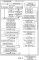
- a computing system 10 comprising, by way of non-limiting example, an input sensor 12, processor 14, and a memory 16 storing executable instructions 17 that, in response to execution by the processor 14, cause the processor 14 to collect input data 18 related to at least a portion of an object or an environment from the input sensor 12, execute a feature extractor 46 to extract features 48 for a plurality of data elements 20, 26, 32 of the input data 18, execute a clustering model 54 configured to cluster the plurality of data elements 20, 26, 32 of the input data 18 into a plurality of feature clusters 56 based on similarities 52 of the extracted features 48 to each other, label a plurality of target clusters 62 of the plurality of feature clusters 56 and a plurality of data elements 64 of the plurality of target clusters 62 with respective predetermined labels 58, generate a training dataset 72 including the plurality of data elements 64 of the plurality of target clusters 62, and train a machine learning model 66 using the training dataset 72 to predict a label 68
- the respective predetermined labels 58 of the plurality of target clusters 62 correspond to prediction labels 68 of the machine learning model 66 configured to recognize elements of the object or the environment.
- the object is all or a portion of an aeronautical or space vehicle such as an aircraft, rocket, or satellite
- the environment is an aeronautical or space environment in which such an aeronautical or space vehicle is manufactured or used.
- the computing system 10 comprises, by way of non-limiting example, a camera 12, processor 14, and a memory 16 storing executable instructions 17 that, in response to execution by the processor 14, cause the processor 14 to collect image data 18 related to at least a portion of an object or an environment from the camera 12, perform object detection to crop images 20, 26, 32 of the image data 18 to generate a plurality of cropped images 40 capturing detected objects, execute a feature extractor 46 to extract features 48 for a plurality of cropped images 40 of the image data 18, execute a clustering model 54 configured to cluster the plurality of cropped images 44 of the image data 18 into a plurality of feature clusters 56 based on similarities 52 of the extracted features 48 to each other, label a plurality of target clusters 62 of the plurality of feature clusters 56 and a plurality of cropped images 64 of the plurality of target clusters 62 with respective predetermined object labels 58, generate a training dataset 72 including the plurality of cropped images 64 of the plurality of target clusters
- Fig. 1 depicts a computing system 10 in which input data 18 from the input sensor 12 is inputted and used to train a machine learning model configured to detect objects in the images 20, 26, 32 of the input data 18.
- the input sensor 12 can be configured as a camera, such as an RGB or infrared camera, for example.
- visual data, including images, videos 22, and 3-D objects 28 are included in the input data 18 in the example of Fig.
- the present invention is not limited to raw visual data, and other types of input data 18 can be processed by the computing system 10, including raw text data, raw graph data, raw audio data, and raw 3-D documents or files, for example.
- the data elements 64 can be word tokens, and the features 48 can be token embeddings, among other options.
- the data elements 64 can be graph vectors, and the features 48 can be graph vector embeddings, node embeddings, and/or edge embeddings, which may be used together or separately for clustering the graph data and training a pre-trained model to predict graph elements.
- the data elements 64 can be audio chunks, and the features 48 can be audio chunk embeddings, among other options.
- the videos 22 of the input data 18 can be processed by a frame reducer 24 to generate reduced images 26 with reduced frames.
- a view augmentation algorithm 30 can process the 3-D objects 28 and generate stacked view images 32.
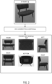
- Fig. 2 an example is depicted of a 3-D object 28 of a chair, which is processed by a view augmentation algorithm 30 to extract 2D stacked view images 32 depicting different views of the 3-D object 28.
- the view augmentation algorithm 30 rotates the 3-D object 28 on every axis in predetermined angle intervals when extracting the stacked view images 32 depicting the different views.
- the stacked view images 32 can be formatted as a tensor file.
- a region of interest extractor 34 receives the images 20 of the input data 18, the reduced images 26 generated by the frame reducer 24, and the stacked view images 32 generated by the view augmentation algorithm 30. The region of interest extractor 34 then extracts region of interest images 36.
- the region of interest extractor 34 can perform motion detection for the temporal data of the images 20, 26, 32 including time series data. Motion detection can be performed so that only a select number of images in the input data 18 is analyzed, without analyzing an entire set of the images 20, 26, 32 in the input data 18 data, thereby conserving computing resources.
- a structural similarity index measurement (SSIM) algorithm can be used to implement motion detection, in which motion is detected based on the images' pixel changes which are evaluated based on a similarity score between zero and one.
- the similarity score evaluates a similarity between the pixels of pairs of images from two different points in time. When the similarity score falls below a predetermined score threshold, so that the visual content (pixel values) between the pairs of images is sufficiently different from each other, then the system determines that motion has been detected.
- the pairs of images with similarity scores that exceed the predetermined score threshold are ignored by the region of interest extractor 34. Accordingly, the total number of images that are subsequently processed can be reduced, thereby reducing processing times and saving computing resources.
- a different similarity algorithm may be used instead of the SSIM algorithm, such as an algorithm that computes the Euclidean distance, Manhattan distance, Minkowski distance, Hausdorff distance, Jaccard distance, etc., between two regions of interest images 36.
- the region of interest images 36 that are extracted by the region of interest extractor 34 are subsequently processed by an object detector 28 comprising multiple convolutional neural network (CNN) layers 38a, which are configured to place bounding boxes over any detected objects.
- the classification layer of the CNN (the last layer of the CNN) can be omitted in the object detector 28 so that object classification is not performed by the multiple CNNs 38a.
- Fig. 3 an example is depicted of a region of interest image 36 of an aircraft skin in which a rivet is detected by the object detector 38. Accordingly, the object detector 38 places a bounding box 40a over the detected rivet and generates a cropped image 40 capturing the detected rivet.
- the bounding box 40a can have a coordinate over the image 36.
- the cropped images 40 are filtered based on aspect ratio and/or pixel size before the feature extractor 46 extracts the features 48 from the cropped images 40.
- the cropping filter 42 is configured to filter the cropped images 40 to only allow filtered cropped images 44 to be processed by the feature extractor 46.
- the cropped images 40 can be filtered by horizontal aspect ratio, which is the ratio of the width to the height of the cropped image 40, or filtered by vertical aspect ratio, which is the ratio of the height to the width of the cropped image 40.
- Cropped images 40 with horizontal aspect ratios above a predetermined threshold (2 pixels by 220 pixels, for example) can be filtered out, so that elongated cropped images 40 are not processed any further.
- cropped images 40 can be filtered by pixel size, so that croppings that are smaller than a predetermined number of pixels, such as 3 pixels, can be filtered out, so that extraneous cropped images 40 are not processed any further.
- a feature extractor 46 receives the filtered cropped images 44 as input and extracts features 48 or embeddings of the filtered cropped images 44.
- the extracted features 48 comprise feature vectors with multiple layers and attributes. Each of the multiple layers can have a normalized value between zero and one, for example.
- a similarity evaluator 50 then calculates pairwise similarity values 52 between the extracted features 48 of the filtered cropped images 44.
- the similarity values 52 can be calculated using a cosine similarity metrics function to determine cosine distance, for example.
- the cosine similarity metrics function has been found to produce superior results for visual data. Alternatively, in other scenarios other distance measures, such as Manhattan distance, Minkowski distance, Hausdorff distance, Jaccard distance, etc., could be utilized.
- a clustering model 54 receives the filtered cropped images 44, the extracted features 48 corresponding to the filtered cropped images 44, and the pairwise similarity values 52 as input, and performs clustering of the extracted features 48 in a latent space. Feature pairs with pairwise similarity values 52 that are greater than a predetermined threshold can be assigned into a cluster.
- the feature clusters 56 outputted by the clustering model 54 has a plurality of feature clusters 56 and images 44 of the plurality of feature clusters 56 which are labeled with respective predetermined labels 58.
- a clustering filter 60 filters out the feature clusters 56 further to output filtered clusters 62 and a smaller set of images 64 which are labeled with the respective predetermined labels 58.
- pairwise similarity values 52 can be performed using a hierarchical clustering method.
- a hierarchical clustering method can be used to organize the filtered cropped images 44 into a hierarchy 55 of filtered cropped images 44, in which the filtered cropped images 44 are linked to each other via linkages. Filtered cropped images 44 with average pairwise similarity values that are relatively higher are linked more closely together than clusters with average pairwise similarity values that are relatively lower.
- a given set of linkages is below a first predetermined height ratio threshold, within a first predetermined height ratio range, the filtered cropped images 44 associated with the given set of linkages are assigned into a first cluster 56a comprising images 44a of the sky.
- the hierarchy 55 of filtered cropped images 44 is analyzed to assign into a second cluster 56b a group of filtered cropped images 44 that are linked to each other with a given set of linkages that is within a second predetermined height ratio range, or below a second predetermined height ratio threshold that is higher than the second predetermined height ratio threshold.
- the second cluster 56b comprises images 44b of a runway.
- FIG. 6 an example of a third feature cluster 56c is depicted, in which images 44c of rivets are clustered together.
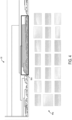
- FIG. 7 exemplary operations of the clustering filter 60 are described, in which outlier images among the images 44c in the third feature cluster 56c are identified and discarded from the third feature cluster 56c.
- the clustering filter 60 can implement an image hashing algorithm 47, in which a hash 49a-d for each respective image 44ca-cd is computed within a given cluster 56c.
- the image hashing algorithm 47 calculates a first hash 49a for the first image 44ca, a second hash 49b for the second image 44cb, a third hash 49c for the third image 44cc, and a fourth hash for the fourth image 44cd.
- the imaging hashing algorithm 47 is preferably a perceptual hashing algorithm, but other known hashing techniques can alternatively be implemented, including average hashing, wavelet hashing, or other known hashing techniques.
- One perceptual hashing algorithm that may be utilized in this implementation is the pHash algorithm, which uses a discrete cosine transform to extract the relevant channels from the image and compute the hash based on the 8 ⁇ 8 discrete cosine transform result.
- the computed hash outputted by the pHash algorithm is a vector of floating point values.
- pairwise distances between the hash for a given image and the hashes for the rest of the images in the given cluster are calculated.
- the lighter colored squares indicate relatively smaller distances between the pairs of hashes, while the darker colored squares indicate relatively greater distances between the pairs of hashes.
- the predetermined distance threshold can be set based on a distribution of distances. As one example, the predetermined distance threshold can be set as ⁇ ⁇ 3 ⁇ for a 95% confidence interval.
- the distance matrix 51 can preferably calculate the pairwise distances between the hashes 49a-d of the images 44ca-cd as XOR distances, in which an XOR operation is performed on binary values of the hashes of a pair of images, and the number of 1's in the result is calculated as the distance.
- other distances can alternatively be calculated, including Euclidean distances and Hamming distances. In the example of Fig.
- three of the images 44ca, 44cb, 44cc within the third feature cluster 56c are oval-shaped, and only one image 44cd within the third feature cluster 56c is rectangularly shaped.
- the distances between the hash 49d for the rectangularly shaped image 44cd and the hashes 49a-c for the other images 44ca-cc is relatively greater (as indicated by squares with darker colors) than the distances between pairs of hashes 49a-c among the oval-shaped images 44ca-cc which are relatively smaller (as indicated by squares with lighter colors).
- the pairwise distances between hashes 49a-c for the oval-shaped images 44ca-cc and the hash 49d for the rectangularly shaped image 44cd are greater than the pairwise distances among the hashes 49a-c of pairs of oval-shaped images 44ca-cc.
- the rectangularly shaped image 44cd can be easily identified within the given cluster 56c as an outlier image and subsequently discarded.
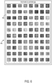
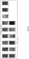
- filtered feature clusters 62 are shown, in which the clustering model 54 has labeled a plurality of target clusters 62 of the plurality of feature clusters 56 and images 64 of the plurality of target clusters 62 with respective predetermined labels 58, which are numerically labeled as ⁇ cluster 0', ⁇ cluster 1', and so forth in this example.
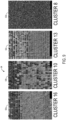
- Fig. 9 a magnified view of four of the feature clusters 62a-d is depicted, in which the images 64 of the plurality of target clusters 62 are more clearly visible.
- the filtered clusters 62 are inputted into a training dataset generator 70 to generate a training dataset 72 based on a standard training dataset format, which can be Yolo or Coco, for example.
- the training dataset generator 70 replaces the predetermined labels 58 of the filtered clusters 62 with predetermined labels 68 from a pre-trained model 66 by matching the clusters of the pre-trained model 66 with the filtered clusters 62 generated by the clustering model 54 using an inference algorithm.
- the generated training dataset 72 includes the filtered clusters 62 and images 64 from the filtered clusters 62 which are labeled with labels 68 from the pre-trained model 66.
- the pre-trained model 66 can be based on a convolutional neural network.
- a trainer 74 trains the pre-trained model 66 using the generated training dataset 72, performing hyper-parameter fine-tuning for all clusters included in the training dataset 72.
- the initially trained model 76 is then evaluated with an evaluator 78.
- the evaluated model 80 is then registered in a model registry 82 and then deployed as a final trained model 84 on a user's computing device for object detection. Accordingly, the training of the pre-trained model 66 can be automated with minimal to no human involvement in supervising the training process.
- the above-described computing system can be applied in quality inspections to detect features on an aircraft skin such as scratches, rivets, dents, cracks, etc.
- an object detector 38 configured to detect scratches on aircraft skin can generate cropped images 40 of scratches on the aircraft skin.
- Filtered cropped images 44 of the scratches can be inputted into a clustering model 54, and features 48 of the filtered cropped images 44 can be clustered into feature clusters 56, which are further filtered to generate a training dataset 72, which is used to train a pre-training machine learning model 66 to improve its performance in detecting scratches on images of aircraft skin.
- the above-described computing system can also be applied in manufacturing applications to detect other objects that can be manufactured by a given manufacturing process, for example.
- 3D objects 28 of various objects can be processed by the view augmentation algorithm 30 to generate stacked view images 32 of the various objects.
- the stacked view images 32 are cropped and filtered, and then features 48 are extracted to cluster the stacked view images 32 using the clustering model 54, the stacked view images 32 of objects with similar three-dimensional geometries would tend to cluster together.
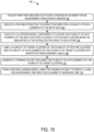
- Fig. 10 a flowchart is illustrated of a first computerized method 100 for training a machine learning model.
- the following description of the first computerized method 100 is provided with reference to the software and hardware components described above and shown in Figs. 1-3 . It will be appreciated that first computerized method 100 also can be performed in other contexts using other suitable hardware and software components.
- Step 102 is performed to collect input data related to at least a portion of an object or an environment from an input sensor.
- Step 104 is performed to execute a feature extractor to extract features for a plurality of data elements of the input data.
- Step 106 is performed to execute a clustering model configured to cluster the plurality of data elements of the input data into a plurality of feature clusters based on similarities of the extracted features to each other.
- Step 108 is performed to label a plurality of target clusters of the plurality of feature clusters and a plurality of data elements of the plurality of target clusters with respective predetermined labels.
- Step 110 is performed to generate a training dataset including the plurality of data elements of the plurality of target clusters.
- Step 112 is performed to train a machine learning model using the training dataset to predict a label for an inference time input data element at inference time.
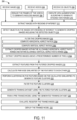
- FIG. 11 a flowchart is illustrated of a second computerized method 200 for training a machine learning model.
- the following description of the second computerized method 200 is provided with reference to the software and hardware components described above and shown in Figs. 1-3 . It will be appreciated that the second computerized method 200 also can be performed in other contexts using other suitable hardware and software components.
- images are received.
- videos are received.
- the frames of the videos are reduced to generate reduced images.
- 3-D objects are received.
- a view augmentation algorithm is executed on the 3-D objects to generate stacked view images.
- Step 212 images with regions of interest are extracted from the received images, reduced images, and stacked view images.
- objects are detected in the images with regions of interest to generate cropped images including the detected objects.
- the cropped images are filtered.
- Step 216 can include, by way of non-limiting example, step 216a of computing horizontal aspect ratios, step 216b of computing vertical aspect ratios, step 216c of extracting cropped images within an allowable horizontal aspect ratio range and within an allowable vertical aspect ratio range and/or step 216d of extracting cropped images above a predetermined number of pixels.
- features are extracted from the filtered cropped images.
- pairwise similarities of the features to each other are calculated.
- clustering is performed on the features based on the calculated similarities to generate feature clusters.
- the feature clusters are filtered.
- a training dataset is generated using the filtered feature clusters.
- a pre-trained model is trained using the generated training dataset.
- the training model is trained and registered in a model registry.
- the trained model is deployed on the user's computing device.
- the above-described system and method are configured to train a machine learning model by efficiently generating a diverse, specific, and accurate training dataset with reduced computing resources.
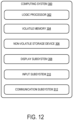
- Fig. 12 schematically shows a non-limiting embodiment of a computing system 300 that can enact one or more of the methods and processes described above.
- Computing system 300 is shown in simplified form.
- Computing system 300 can embody the computing system 10 illustrated in Fig. 1 .
- Computing system 300 can take the form of one or more personal computers, server computers, tablet computers, home-entertainment computers, network computing devices, gaming devices, mobile computing devices, mobile communication devices (e.g., smart phone), and/or other computing devices, and wearable computing devices such as smart wristwatches and head mounted augmented reality devices.
- Computing system 300 includes a logic processor 302, volatile memory 304, and a non-volatile storage device 306.
- Computing system 300 can optionally include a display subsystem 308, input subsystem 310, communication subsystem 312, and/or other components not shown in Fig. 12 .
- Logic processor 302 includes one or more physical devices configured to execute instructions.
- the logic processor can be configured to execute instructions that are part of one or more applications, programs, routines, libraries, objects, components, data structures, or other logical constructs. Such instructions can be implemented to perform a task, implement a data type, transform the state of one or more components, achieve a technical effect, or otherwise arrive at a desired result.
- the logic processor 302 can include one or more physical processors (hardware) configured to execute software instructions. Additionally or alternatively, the logic processor can include one or more hardware logic circuits or firmware devices configured to execute hardware-implemented logic or firmware instructions.
- Processors of the logic processor 302 can be single-core or multi-core, and the instructions executed thereon can be configured for sequential, parallel, and/or distributed processing. Individual components of the logic processor optionally can be distributed among two or more separate devices, which can be remotely located and/or configured for coordinated processing. Aspects of the logic processor can be virtualized and executed by remotely accessible, networked computing devices configured in a cloud-computing configuration. In such an example, these virtualized aspects are run on different physical logic processors of various different machines, it will be understood.
- Non-volatile storage device 306 includes one or more physical devices configured to hold instructions executable by the logic processors to implement the methods and processes described herein. When such methods and processes are implemented, the state of non-volatile storage device 306 can be transformed-e.g., to hold different data.
- Non-volatile storage device 306 can include physical devices that are removable and/or built in.
- Non-volatile storage device 306 can include optical memory (e.g., CD, DVD, HD-DVD, Blu-Ray Disc, etc.), semiconductor memory (e.g., ROM, EPROM, EEPROM, FLASH memory, etc.), and/or magnetic memory (e.g., hard-disk drive, floppy-disk drive, tape drive, MRAM, etc.), or other mass storage device technology.
- Non-volatile storage device 306 can include, by way of non-limiting example, nonvolatile, dynamic, static, read/write, read-only, sequential-access, location-addressable, file-addressable, and/or content-addressable devices. It will be appreciated that non-volatile storage device 306 is configured to hold instructions even when power is cut to the non-volatile storage device 306.
- Volatile memory 304 can include physical devices that include random access memory. Volatile memory 304 is typically utilized by logic processor 302 to temporarily store information during processing of software instructions. It will be appreciated that volatile memory 304 typically does not continue to store instructions when power is cut to the volatile memory 304.
- logic processor 302, volatile memory 304, and non-volatile storage device 306 can be integrated together into one or more hardware-logic components.
- hardware-logic components can include, by way of non-limiting example, field-programmable gate arrays (FPGAs), program- and application-specific integrated circuits (PASIC / ASICs), program- and application-specific standard products (PSSP / ASSPs), system-on-a-chip (SOC), and complex programmable logic devices (CPLDs), for example.
- FPGAs field-programmable gate arrays
- PASIC / ASICs program- and application-specific integrated circuits
- PSSP / ASSPs program- and application-specific standard products
- SOC system-on-a-chip
- CPLDs complex programmable logic devices
- module can be used to describe an aspect of computing system 300 typically implemented in software by a processor to perform a particular function using portions of volatile memory, which function involves transformative processing that specially configures the processor to perform the function.
- a module, program, or engine can be instantiated via logic processor 302 executing instructions held by non-volatile storage device 306, using portions of volatile memory 304.
- modules, programs, and/or engines can be instantiated from the same application, service, code block, object, library, routine, API, function, etc.
- the same module, program, and/or engine can be instantiated by different applications, services, code blocks, objects, routines, APIs, functions, etc.
- module can encompass individual or groups of executable files, data files, libraries, drivers, scripts, database records, etc.
- display subsystem 308 can be used to present a visual representation of data held by non-volatile storage device 306.
- the visual representation can take the form of a graphical user interface (GUI).
- GUI graphical user interface
- the state of display subsystem 308 can likewise be transformed to visually represent changes in the underlying data.
- Display subsystem 308 can include one or more display devices utilizing virtually any type of technology. Such display devices can be combined with logic processor 302, volatile memory 304, and/or non-volatile storage device 306 in a shared enclosure, or such display devices can be peripheral display devices.
- input subsystem 310 can comprise or interface with one or more user-input devices such as a keyboard, mouse, touch screen, or game controller.
- the input subsystem can comprise or interface with selected natural user input (NUI) componentry.
- NUI natural user input
- Such componentry can be integrated or peripheral, and the transduction and/or processing of input actions can be handled on- or off-board.
- NUI componentry can include a microphone for speech and/or voice recognition; an infrared, color, stereoscopic, and/or depth camera for machine vision and/or gesture recognition; a head tracker, eye tracker, accelerometer, and/or gyroscope for motion detection and/or intent recognition; as well as electric-field sensing componentry for assessing brain activity; and/or any other suitable sensor.
- communication subsystem 312 can be configured to communicatively couple various computing devices described herein with each other, and with other devices.
- Communication subsystem 312 can include wired and/or wireless communication devices compatible with one or more different communication protocols.
- the communication subsystem can be configured for communication via a wireless telephone network, or a wired or wireless local- or wide-area network, such as a HDMI over Wi-Fi connection.
- the communication subsystem can allow computing system 300 to send and/or receive messages to and/or from other devices via a network such as the Internet.
- a and/or B has the following OR truth table.
- a computing system comprising: an input sensor; a processor; and a memory storing executable instructions that, in response to execution by the processor cause the processor to: collect input data related to at least a portion of an object or an environment from the input sensor; execute a feature extractor to extract features for a plurality of data elements of the input data; execute a clustering model configured to cluster the plurality of data elements of the input data into a plurality of feature clusters based on similarities of the extracted features to each other; label a plurality of target clusters of the plurality of feature clusters and the plurality of data elements of the plurality of target clusters with respective predetermined labels; generate a training dataset including the plurality of data elements of the plurality of target clusters; and train a machine learning model using the training dataset to predict a label for an inference time input data element at inference time, wherein the respective predetermined labels of the plurality of target clusters correspond to prediction labels of the machine learning model configured to recognize elements of the object or the environment.
- an object detector comprising multiple convolutional neural networks is used to crop the images to generate cropped images capturing detected objects; and the feature extractor is executed to extract features from the cropped images.
- Clause 5 The computing system of claim 3, wherein the cropped images are filtered before the feature extractor extracts the features from the cropped images; and the cropped images are filtered based on aspect ratio and/or pixel size.
- Clause 6 The computing system of claim 1, wherein the data elements are clustered into the plurality of feature clusters by calculating pairwise similarity values between the extracted features of the data elements.
- Clause 7 The computing system of claim 6, wherein the similarity values are calculated using a cosine similarity metrics function.
- Clause 8 The computing system of claim 1, wherein the data elements are clustered into the plurality of feature clusters using a hierarchical clustering method.
- Clause 9 The computing system of claim 8, wherein the data elements are linked to each other via linkages; and when a given set of linkages is within a predetermined height ratio range, data elements associated with the given set of linkages are assigned into a target cluster of the plurality of target clusters.
- Clause 10 The computing system of claim 1, wherein the respective predetermined labels of the target clusters are replaced by the prediction labels of the machine learning model using an inference algorithm to generate the training dataset.
- a method comprising steps to: collect input data related to at least a portion of an object or an environment from an input sensor; execute a feature extractor to extract features for a plurality of data elements of the input data; execute a clustering model configured to cluster the plurality of data elements of the input data into a plurality of feature clusters based on similarities of the extracted features to each other; label a plurality of target clusters of the plurality of feature clusters and a plurality of data elements of the plurality of target clusters with respective predetermined labels; generate a training dataset including the plurality of data elements of the plurality of target clusters; and train a machine learning model using the training dataset to predict a label for an inference time input data element at inference time, wherein the respective predetermined labels of the plurality of target clusters correspond to prediction labels of the machine learning model configured to recognize elements of the object or the environment.
- Clause 13 The method of claim 12, wherein object detection is performed to crop the images to generate cropped images capturing detected objects; and features are extracted from the cropped images.
- Clause 14 The method of claim 13, wherein the input data includes 3-D objects; and a view augmentation algorithm is used to process the 3-D objects and generate stacked view images as the plurality of data elements.
- Clause 15 The method of claim 13, wherein the cropped images are filtered before the feature extractor extracts the features from the cropped images; and the cropped images are filtered based on aspect ratio and/or pixel size.
- Clause 16 The method of claim 11, wherein the data elements are clustered into the plurality of feature clusters by calculating pairwise similarity values between the extracted features of the data elements.
- Clause 18 The method of claim 11, wherein the data elements are clustered into the plurality of feature clusters using a hierarchical clustering method.
- a computing system comprising: a camera; a processor; and a memory storing executable instructions that, in response to execution by the processor cause the processor to: collect image data related to at least a portion of an object or an environment from the camera; perform object detection to crop images of the image data to generate a plurality of cropped images capturing detected objects; execute a feature extractor to extract features for the plurality of cropped images; execute a clustering model configured to cluster the plurality of cropped images of the image data into a plurality of feature clusters based on similarities of the extracted features to each other; label a plurality of target clusters of the plurality of feature clusters and a plurality of cropped images of the plurality of target clusters with respective predetermined object labels; generate a training dataset including the plurality of cropped images of the plurality of target clusters; and train an object detection machine learning model using the training dataset to predict an object label for an inference time image at inference time, wherein the respective predetermined object labels of the plurality of target clusters correspond to prediction
Landscapes
- Engineering & Computer Science (AREA)
- Theoretical Computer Science (AREA)
- Computer Vision & Pattern Recognition (AREA)
- Multimedia (AREA)
- General Physics & Mathematics (AREA)
- Physics & Mathematics (AREA)
- Evolutionary Computation (AREA)
- Artificial Intelligence (AREA)
- Medical Informatics (AREA)
- Software Systems (AREA)
- General Health & Medical Sciences (AREA)
- Databases & Information Systems (AREA)
- Computing Systems (AREA)
- Health & Medical Sciences (AREA)
- Image Analysis (AREA)
Abstract
A computing system is configured to collect input data related to at least a portion of an object or an environment from the input sensor, execute a feature extractor to extract features for data elements of the input data, execute a clustering model configured to cluster the data elements of the input data into feature clusters based on similarities of the extracted features to each other, label a target clusters of the feature clusters and data elements of the target clusters with respective predetermined labels, generate a training dataset including the data elements of the target clusters, and train a machine learning model using the training dataset to predict a label for an inference time input data element at inference time. The respective predetermined labels of the target clusters correspond to prediction labels of the machine learning model.
Description
- CROSS REFERENCE TO RELATED APPLICATIONSThis application claims priority to
U.S. Provisional Patent Application No. 63/481,151, entitled SYSTEM AND METHOD FOR TRAINING A MACHINE LEARNING MODEL, filed January 23, 2023 - The field of the present disclosure relates generally to machine learning systems and, more specifically, to systems and methods for training machine learning models.
- In varied applications, including autonomous vehicles, quality inspection, surveillance camera systems, security monitoring systems, logistics and asset tracking, and path finding and navigation systems, large sets of visual data are clustered for object detection. However, clustering visual data is challenging, and often utilizes humans who provide ground truth labels for the image data. Labeling of large-scale data sets of image data generally has to be done on an image-by-image basis, which is both costly and time consuming. Various challenges exist to training machine learning models to perform object detection and feature extraction in such image data. For example, training of a machine learning system can be frustrated if the image dataset is not (a) diverse (incorporating various views and angles of an object), (b) specific (which can be difficult if the object's visual representation changes over time or if different environmental conditions occur), and (c) accurate (which can be problematic due to unintended bias by human labelers, judgment of classes, and data mismatch). Errors and mistakes of these types in datasets, tied to human involvement, can result in false positives and/or negatives.
- In view of the above, a computing system is provided, comprising an input sensor, a processor, and a memory storing executable instructions that, in response to execution by the processor, cause the processor to collect input data related to at least a portion of an object or an environment from the input sensor, execute a feature extractor to extract features for a plurality of data elements of the input data, execute a clustering model configured to cluster the plurality of data elements of the input data into a plurality of feature clusters based on similarities of the extracted features to each other, label a plurality of target clusters of the plurality of feature clusters and a plurality of data elements of the plurality of target clusters with respective predetermined labels, generate a training dataset including the plurality of data elements of the plurality of target clusters, and train a machine learning model using the training dataset to predict a label for an inference time input data element at inference time. The respective predetermined labels of the plurality of target clusters correspond to prediction labels of the machine learning model configured to recognize elements of the object or the environment.
- The features, functions, and advantages that have been discussed can be achieved independently in various embodiments or can be combined in yet other embodiments further details of which can be seen with reference to the following description and drawings.
-
-
Fig. 1 illustrates a schematic view of a computing system according to an example embodiment of the present disclosure. -
Fig. 2 illustrates operations of the view augmentation algorithm of the computing system ofFig. 1 . -
Fig. 3 illustrates operations of the object detector of the computing system ofFig. 1 . -
Fig. 4 illustrates an exemplary first feature cluster generated by the computing system ofFig. 1 . -
Fig. 5 illustrates an exemplary second feature cluster generated by the computing system ofFig. 1 . -
Fig. 6 illustrates an exemplary third feature cluster generated by the computing system ofFig. 1 . -
Fig. 7 illustrates an exemplary operation of the clustering filter of the computing system ofFig. 1 . -
Fig. 8 illustrates some exemplary filtered feature clusters generated by the computing system ofFig. 1 . -
Fig. 9 illustrates a magnified view of some exemplary filtered feature clusters generated by the computing system ofFig. 1 . -
Fig. 10 is a flowchart of a first computerized method for training a machine learning model according to an example embodiment of the present disclosure. -
Fig. 11 is a flowchart of a second computerized method for training a machine learning model according to an example embodiment of the present disclosure. -
Fig. 12 shows an embodiment of an example computing environment of the present disclosure. - In view of the above issues, the present disclosure describes a system and method for training a machine learning model by efficiently generating a diverse, specific, and accurate training dataset with reduced computing resources. Such a system and method are described below in further detail.
- Referring to
Fig. 1 , an embodiment of acomputing system 10 is depicted, comprising, by way of non-limiting example, aninput sensor 12,processor 14, and amemory 16 storingexecutable instructions 17 that, in response to execution by theprocessor 14, cause theprocessor 14 to collectinput data 18 related to at least a portion of an object or an environment from theinput sensor 12, execute afeature extractor 46 to extractfeatures 48 for a plurality ofdata elements input data 18, execute a clustering model 54 configured to cluster the plurality ofdata elements input data 18 into a plurality of feature clusters 56 based onsimilarities 52 of the extractedfeatures 48 to each other, label a plurality of target clusters 62 of the plurality of feature clusters 56 and a plurality ofdata elements 64 of the plurality of target clusters 62 with respectivepredetermined labels 58, generate atraining dataset 72 including the plurality ofdata elements 64 of the plurality of target clusters 62, and train amachine learning model 66 using thetraining dataset 72 to predict alabel 68 for an inference time input data element at inference time. The respectivepredetermined labels 58 of the plurality of target clusters 62 correspond toprediction labels 68 of themachine learning model 66 configured to recognize elements of the object or the environment. In one particular example, the object is all or a portion of an aeronautical or space vehicle such as an aircraft, rocket, or satellite, and the environment is an aeronautical or space environment in which such an aeronautical or space vehicle is manufactured or used. - In configurations in which the
input data 18 is image data, thecomputing system 10 comprises, by way of non-limiting example, acamera 12,processor 14, and amemory 16 storingexecutable instructions 17 that, in response to execution by theprocessor 14, cause theprocessor 14 to collectimage data 18 related to at least a portion of an object or an environment from thecamera 12, perform object detection to cropimages image data 18 to generate a plurality of croppedimages 40 capturing detected objects, execute afeature extractor 46 to extractfeatures 48 for a plurality of croppedimages 40 of theimage data 18, execute a clustering model 54 configured to cluster the plurality of croppedimages 44 of theimage data 18 into a plurality of feature clusters 56 based onsimilarities 52 of the extractedfeatures 48 to each other, label a plurality of target clusters 62 of the plurality of feature clusters 56 and a plurality of croppedimages 64 of the plurality of target clusters 62 with respectivepredetermined object labels 58, generate atraining dataset 72 including the plurality of croppedimages 64 of the plurality of target clusters 62, and train an object detectionmachine learning model 66 using thetraining dataset 72 to predict anobject label 68 for an inference time image at inference time. The respectivepredetermined object labels 58 of the plurality of target clusters 62 correspond toprediction object labels 68 of the object detectionmachine learning model 66 configured to recognize elements of the object or the environment.Fig. 1 depicts acomputing system 10 in whichinput data 18 from theinput sensor 12 is inputted and used to train a machine learning model configured to detect objects in theimages input data 18. Theinput sensor 12 can be configured as a camera, such as an RGB or infrared camera, for example. Although visual data, including images,videos 22, and 3-D objects 28 are included in theinput data 18 in the example ofFig. 1 , it will be appreciated that the present invention is not limited to raw visual data, and other types ofinput data 18 can be processed by thecomputing system 10, including raw text data, raw graph data, raw audio data, and raw 3-D documents or files, for example. In examples in which theinput data 18 is raw text data, thedata elements 64 can be word tokens, and thefeatures 48 can be token embeddings, among other options. In examples in which theinput data 18 is graph data, thedata elements 64 can be graph vectors, and thefeatures 48 can be graph vector embeddings, node embeddings, and/or edge embeddings, which may be used together or separately for clustering the graph data and training a pre-trained model to predict graph elements. In examples in which theinput data 18 is raw audio data, thedata elements 64 can be audio chunks, and thefeatures 48 can be audio chunk embeddings, among other options. - The
videos 22 of theinput data 18 can be processed by aframe reducer 24 to generate reducedimages 26 with reduced frames. Aview augmentation algorithm 30 can process the 3-D objects 28 and generate stackedview images 32. Turning briefly toFig. 2 , an example is depicted of a 3-D object 28 of a chair, which is processed by aview augmentation algorithm 30 to extract 2D stackedview images 32 depicting different views of the 3-D object 28. Theview augmentation algorithm 30 rotates the 3-D object 28 on every axis in predetermined angle intervals when extracting the stackedview images 32 depicting the different views. The stackedview images 32 can be formatted as a tensor file. - Returning to
Fig. 1 , a region ofinterest extractor 34 receives theimages 20 of theinput data 18, the reducedimages 26 generated by theframe reducer 24, and the stackedview images 32 generated by theview augmentation algorithm 30. The region ofinterest extractor 34 then extracts region ofinterest images 36. For example, the region ofinterest extractor 34 can perform motion detection for the temporal data of theimages input data 18 is analyzed, without analyzing an entire set of theimages input data 18 data, thereby conserving computing resources. - In the region of
interest extractor 34, a structural similarity index measurement (SSIM) algorithm can be used to implement motion detection, in which motion is detected based on the images' pixel changes which are evaluated based on a similarity score between zero and one. The similarity score evaluates a similarity between the pixels of pairs of images from two different points in time. When the similarity score falls below a predetermined score threshold, so that the visual content (pixel values) between the pairs of images is sufficiently different from each other, then the system determines that motion has been detected. The pairs of images with similarity scores that exceed the predetermined score threshold are ignored by the region ofinterest extractor 34. Accordingly, the total number of images that are subsequently processed can be reduced, thereby reducing processing times and saving computing resources. Alternatively a different similarity algorithm may be used instead of the SSIM algorithm, such as an algorithm that computes the Euclidean distance, Manhattan distance, Minkowski distance, Hausdorff distance, Jaccard distance, etc., between two regions ofinterest images 36. - The region of
interest images 36 that are extracted by the region ofinterest extractor 34 are subsequently processed by anobject detector 28 comprising multiple convolutional neural network (CNN)layers 38a, which are configured to place bounding boxes over any detected objects. The classification layer of the CNN (the last layer of the CNN) can be omitted in theobject detector 28 so that object classification is not performed by themultiple CNNs 38a. Turning briefly toFig. 3 , an example is depicted of a region ofinterest image 36 of an aircraft skin in which a rivet is detected by theobject detector 38. Accordingly, theobject detector 38 places a boundingbox 40a over the detected rivet and generates a croppedimage 40 capturing the detected rivet. The boundingbox 40a can have a coordinate over theimage 36. - Returning to
Fig. 1 , thecropped images 40 are filtered based on aspect ratio and/or pixel size before thefeature extractor 46 extracts thefeatures 48 from thecropped images 40. Thecropping filter 42 is configured to filter thecropped images 40 to only allow filteredcropped images 44 to be processed by thefeature extractor 46. The croppedimages 40 can be filtered by horizontal aspect ratio, which is the ratio of the width to the height of the croppedimage 40, or filtered by vertical aspect ratio, which is the ratio of the height to the width of the croppedimage 40. Croppedimages 40 with horizontal aspect ratios above a predetermined threshold (2 pixels by 220 pixels, for example) can be filtered out, so that elongated croppedimages 40 are not processed any further. Additionally or alternatively, croppedimages 40 can be filtered by pixel size, so that croppings that are smaller than a predetermined number of pixels, such as 3 pixels, can be filtered out, so that extraneous croppedimages 40 are not processed any further. - A
feature extractor 46 receives the filtered croppedimages 44 as input and extracts features 48 or embeddings of the filtered croppedimages 44. The extracted features 48 comprise feature vectors with multiple layers and attributes. Each of the multiple layers can have a normalized value between zero and one, for example. Asimilarity evaluator 50 then calculates pairwise similarity values 52 between the extracted features 48 of the filtered croppedimages 44. The similarity values 52 can be calculated using a cosine similarity metrics function to determine cosine distance, for example. The cosine similarity metrics function has been found to produce superior results for visual data. Alternatively, in other scenarios other distance measures, such as Manhattan distance, Minkowski distance, Hausdorff distance, Jaccard distance, etc., could be utilized. - A clustering model 54 receives the filtered cropped
images 44, the extracted features 48 corresponding to the filtered croppedimages 44, and the pairwise similarity values 52 as input, and performs clustering of the extracted features 48 in a latent space. Feature pairs with pairwise similarity values 52 that are greater than a predetermined threshold can be assigned into a cluster. The feature clusters 56 outputted by the clustering model 54 has a plurality of feature clusters 56 andimages 44 of the plurality of feature clusters 56 which are labeled with respective predetermined labels 58. A clustering filter 60 filters out the feature clusters 56 further to output filtered clusters 62 and a smaller set ofimages 64 which are labeled with the respective predetermined labels 58. - The evaluation of pairwise similarity values 52 can be performed using a hierarchical clustering method. Turning to
Fig. 4 , a hierarchical clustering method can be used to organize the filtered croppedimages 44 into ahierarchy 55 of filtered croppedimages 44, in which the filtered croppedimages 44 are linked to each other via linkages. Filtered croppedimages 44 with average pairwise similarity values that are relatively higher are linked more closely together than clusters with average pairwise similarity values that are relatively lower. In the example ofFig. 4 , when a given set of linkages is below a first predetermined height ratio threshold, within a first predetermined height ratio range, the filtered croppedimages 44 associated with the given set of linkages are assigned into afirst cluster 56a comprising images 44a of the sky. - Turning to
Fig. 5 , thehierarchy 55 of filtered croppedimages 44 is analyzed to assign into asecond cluster 56b a group of filtered croppedimages 44 that are linked to each other with a given set of linkages that is within a second predetermined height ratio range, or below a second predetermined height ratio threshold that is higher than the second predetermined height ratio threshold. In the example ofFig. 5 , thesecond cluster 56b comprisesimages 44b of a runway. - Turning to
Fig. 6 , an example of athird feature cluster 56c is depicted, in whichimages 44c of rivets are clustered together. Turning toFig. 7 , exemplary operations of the clustering filter 60 are described, in which outlier images among theimages 44c in thethird feature cluster 56c are identified and discarded from thethird feature cluster 56c. The clustering filter 60 can implement animage hashing algorithm 47, in which ahash 49a-d for each respective image 44ca-cd is computed within a givencluster 56c. In this example, theimage hashing algorithm 47 calculates afirst hash 49a for the first image 44ca, asecond hash 49b for the second image 44cb, athird hash 49c for the third image 44cc, and a fourth hash for the fourth image 44cd. Theimaging hashing algorithm 47 is preferably a perceptual hashing algorithm, but other known hashing techniques can alternatively be implemented, including average hashing, wavelet hashing, or other known hashing techniques. One perceptual hashing algorithm that may be utilized in this implementation is the pHash algorithm, which uses a discrete cosine transform to extract the relevant channels from the image and compute the hash based on the 8×8 discrete cosine transform result. The computed hash outputted by the pHash algorithm is a vector of floating point values. - Using a
distance matrix 51, pairwise distances between the hash for a given image and the hashes for the rest of the images in the given cluster are calculated. In the graphical depiction of thedistance matrix 51 inFig. 7 , the lighter colored squares indicate relatively smaller distances between the pairs of hashes, while the darker colored squares indicate relatively greater distances between the pairs of hashes. After the pairwise distances between the hashes are calculated, pairs of images with pairwise distances which exceed a predetermined distance threshold are identified. When it is determined that an average pairwise distance between the hash for a given image and the hashes for the rest of the images in the given cluster exceed a predetermined distance threshold, then the given image is discarded from the given cluster. In other words, based on the identification of the pairs of images with pairwise distances which exceed the predetermined threshold, the outlier images are identified and discarded from the given cluster. - The predetermined distance threshold can be set based on a distribution of distances. As one example, the predetermined distance threshold can be set as µ ± 3σ for a 95% confidence interval. The
distance matrix 51 can preferably calculate the pairwise distances between thehashes 49a-d of the images 44ca-cd as XOR distances, in which an XOR operation is performed on binary values of the hashes of a pair of images, and the number of 1's in the result is calculated as the distance. However, other distances can alternatively be calculated, including Euclidean distances and Hamming distances. In the example ofFig. 6 , three of the images 44ca, 44cb, 44cc within thethird feature cluster 56c are oval-shaped, and only one image 44cd within thethird feature cluster 56c is rectangularly shaped. As shown in thedistance matrix 51, the distances between thehash 49d for the rectangularly shaped image 44cd and thehashes 49a-c for the other images 44ca-cc is relatively greater (as indicated by squares with darker colors) than the distances between pairs ofhashes 49a-c among the oval-shaped images 44ca-cc which are relatively smaller (as indicated by squares with lighter colors). In other words, the pairwise distances betweenhashes 49a-c for the oval-shaped images 44ca-cc and thehash 49d for the rectangularly shaped image 44cd are greater than the pairwise distances among thehashes 49a-c of pairs of oval-shaped images 44ca-cc. - Accordingly, the rectangularly shaped image 44cd can be easily identified within the given
cluster 56c as an outlier image and subsequently discarded. - Turning to
Fig. 8 , filtered feature clusters 62 are shown, in which the clustering model 54 has labeled a plurality of target clusters 62 of the plurality of feature clusters 56 andimages 64 of the plurality of target clusters 62 with respectivepredetermined labels 58, which are numerically labeled as `cluster 0', `cluster 1', and so forth in this example. Turning toFig. 9 , a magnified view of four of thefeature clusters 62a-d is depicted, in which theimages 64 of the plurality of target clusters 62 are more clearly visible. Returning toFig. 1 , the filtered clusters 62, including theimages 64 and the respectivepredetermined labels 58, are inputted into atraining dataset generator 70 to generate atraining dataset 72 based on a standard training dataset format, which can be Yolo or Coco, for example. Thetraining dataset generator 70 replaces the predetermined labels 58 of the filtered clusters 62 withpredetermined labels 68 from apre-trained model 66 by matching the clusters of thepre-trained model 66 with the filtered clusters 62 generated by the clustering model 54 using an inference algorithm. The generatedtraining dataset 72 includes the filtered clusters 62 andimages 64 from the filtered clusters 62 which are labeled withlabels 68 from thepre-trained model 66. Thepre-trained model 66 can be based on a convolutional neural network. - A
trainer 74 then trains thepre-trained model 66 using the generatedtraining dataset 72, performing hyper-parameter fine-tuning for all clusters included in thetraining dataset 72. The initially trainedmodel 76 is then evaluated with anevaluator 78. The evaluatedmodel 80 is then registered in amodel registry 82 and then deployed as a final trainedmodel 84 on a user's computing device for object detection. Accordingly, the training of thepre-trained model 66 can be automated with minimal to no human involvement in supervising the training process. - The above-described computing system can be applied in quality inspections to detect features on an aircraft skin such as scratches, rivets, dents, cracks, etc. For example, an
object detector 38 configured to detect scratches on aircraft skin can generate croppedimages 40 of scratches on the aircraft skin. Filtered croppedimages 44 of the scratches can be inputted into a clustering model 54, and features 48 of the filtered croppedimages 44 can be clustered into feature clusters 56, which are further filtered to generate atraining dataset 72, which is used to train a pre-trainingmachine learning model 66 to improve its performance in detecting scratches on images of aircraft skin. - The above-described computing system can also be applied in manufacturing applications to detect other objects that can be manufactured by a given manufacturing process, for example. For example, 3D objects 28 of various objects can be processed by the
view augmentation algorithm 30 to generatestacked view images 32 of the various objects. When thestacked view images 32 are cropped and filtered, and then features 48 are extracted to cluster thestacked view images 32 using the clustering model 54, thestacked view images 32 of objects with similar three-dimensional geometries would tend to cluster together. By identifying objects with similar three-dimensional geometries, the identification of objects that can be manufactured by a given manufacturing process can be facilitated while conserving computing resources. Turning toFig. 10 , a flowchart is illustrated of a firstcomputerized method 100 for training a machine learning model. The following description of the firstcomputerized method 100 is provided with reference to the software and hardware components described above and shown inFigs. 1-3 . It will be appreciated that firstcomputerized method 100 also can be performed in other contexts using other suitable hardware and software components. - Step 102 is performed to collect input data related to at least a portion of an object or an environment from an input sensor. Step 104 is performed to execute a feature extractor to extract features for a plurality of data elements of the input data. Step 106 is performed to execute a clustering model configured to cluster the plurality of data elements of the input data into a plurality of feature clusters based on similarities of the extracted features to each other. Step 108 is performed to label a plurality of target clusters of the plurality of feature clusters and a plurality of data elements of the plurality of target clusters with respective predetermined labels. Step 110 is performed to generate a training dataset including the plurality of data elements of the plurality of target clusters. Step 112 is performed to train a machine learning model using the training dataset to predict a label for an inference time input data element at inference time.
- Turning to
Fig. 11 , a flowchart is illustrated of a secondcomputerized method 200 for training a machine learning model. The following description of the secondcomputerized method 200 is provided with reference to the software and hardware components described above and shown inFigs. 1-3 . It will be appreciated that the secondcomputerized method 200 also can be performed in other contexts using other suitable hardware and software components. - At
step 202, images are received. Atstep 204, videos are received. Atstep 206, the frames of the videos are reduced to generate reduced images. Atstep 208, 3-D objects are received. Atstep 210, a view augmentation algorithm is executed on the 3-D objects to generate stacked view images. - At
step 212, images with regions of interest are extracted from the received images, reduced images, and stacked view images. Atstep 214, objects are detected in the images with regions of interest to generate cropped images including the detected objects. Atstep 216, the cropped images are filtered. Step 216 can include, by way of non-limiting example, step 216a of computing horizontal aspect ratios,step 216b of computing vertical aspect ratios,step 216c of extracting cropped images within an allowable horizontal aspect ratio range and within an allowable vertical aspect ratio range and/orstep 216d of extracting cropped images above a predetermined number of pixels. - At
step 218, features are extracted from the filtered cropped images. Atstep 220, pairwise similarities of the features to each other are calculated. At step 222, clustering is performed on the features based on the calculated similarities to generate feature clusters. At step 224, the feature clusters are filtered. At step 226, a training dataset is generated using the filtered feature clusters. At step 228, a pre-trained model is trained using the generated training dataset. Atstep 230, the training model is trained and registered in a model registry. Atstep 232, the trained model is deployed on the user's computing device. - The above-described system and method are configured to train a machine learning model by efficiently generating a diverse, specific, and accurate training dataset with reduced computing resources.
-
Fig. 12 schematically shows a non-limiting embodiment of acomputing system 300 that can enact one or more of the methods and processes described above.Computing system 300 is shown in simplified form.Computing system 300 can embody thecomputing system 10 illustrated inFig. 1 .Computing system 300 can take the form of one or more personal computers, server computers, tablet computers, home-entertainment computers, network computing devices, gaming devices, mobile computing devices, mobile communication devices (e.g., smart phone), and/or other computing devices, and wearable computing devices such as smart wristwatches and head mounted augmented reality devices. -
Computing system 300 includes alogic processor 302,volatile memory 304, and anon-volatile storage device 306.Computing system 300 can optionally include adisplay subsystem 308,input subsystem 310,communication subsystem 312, and/or other components not shown inFig. 12 . -
Logic processor 302 includes one or more physical devices configured to execute instructions. For example, the logic processor can be configured to execute instructions that are part of one or more applications, programs, routines, libraries, objects, components, data structures, or other logical constructs. Such instructions can be implemented to perform a task, implement a data type, transform the state of one or more components, achieve a technical effect, or otherwise arrive at a desired result. Thelogic processor 302 can include one or more physical processors (hardware) configured to execute software instructions. Additionally or alternatively, the logic processor can include one or more hardware logic circuits or firmware devices configured to execute hardware-implemented logic or firmware instructions. Processors of thelogic processor 302 can be single-core or multi-core, and the instructions executed thereon can be configured for sequential, parallel, and/or distributed processing. Individual components of the logic processor optionally can be distributed among two or more separate devices, which can be remotely located and/or configured for coordinated processing. Aspects of the logic processor can be virtualized and executed by remotely accessible, networked computing devices configured in a cloud-computing configuration. In such an example, these virtualized aspects are run on different physical logic processors of various different machines, it will be understood. -
Non-volatile storage device 306 includes one or more physical devices configured to hold instructions executable by the logic processors to implement the methods and processes described herein. When such methods and processes are implemented, the state ofnon-volatile storage device 306 can be transformed-e.g., to hold different data.Non-volatile storage device 306 can include physical devices that are removable and/or built in.Non-volatile storage device 306 can include optical memory (e.g., CD, DVD, HD-DVD, Blu-Ray Disc, etc.), semiconductor memory (e.g., ROM, EPROM, EEPROM, FLASH memory, etc.), and/or magnetic memory (e.g., hard-disk drive, floppy-disk drive, tape drive, MRAM, etc.), or other mass storage device technology.Non-volatile storage device 306 can include, by way of non-limiting example, nonvolatile, dynamic, static, read/write, read-only, sequential-access, location-addressable, file-addressable, and/or content-addressable devices. It will be appreciated thatnon-volatile storage device 306 is configured to hold instructions even when power is cut to thenon-volatile storage device 306. -
Volatile memory 304 can include physical devices that include random access memory.Volatile memory 304 is typically utilized bylogic processor 302 to temporarily store information during processing of software instructions. It will be appreciated thatvolatile memory 304 typically does not continue to store instructions when power is cut to thevolatile memory 304. - Aspects of
logic processor 302,volatile memory 304, andnon-volatile storage device 306 can be integrated together into one or more hardware-logic components. Such hardware-logic components can include, by way of non-limiting example, field-programmable gate arrays (FPGAs), program- and application-specific integrated circuits (PASIC / ASICs), program- and application-specific standard products (PSSP / ASSPs), system-on-a-chip (SOC), and complex programmable logic devices (CPLDs), for example. - The terms "module," "program," and "engine" can be used to describe an aspect of
computing system 300 typically implemented in software by a processor to perform a particular function using portions of volatile memory, which function involves transformative processing that specially configures the processor to perform the function. Thus, a module, program, or engine can be instantiated vialogic processor 302 executing instructions held bynon-volatile storage device 306, using portions ofvolatile memory 304. It will be understood that different modules, programs, and/or engines can be instantiated from the same application, service, code block, object, library, routine, API, function, etc. Likewise, the same module, program, and/or engine can be instantiated by different applications, services, code blocks, objects, routines, APIs, functions, etc. The terms "module," "program," and "engine" can encompass individual or groups of executable files, data files, libraries, drivers, scripts, database records, etc. - When included,
display subsystem 308 can be used to present a visual representation of data held bynon-volatile storage device 306. The visual representation can take the form of a graphical user interface (GUI). As the herein described methods and processes change the data held by the non-volatile storage device, and thus transform the state of the non-volatile storage device, the state ofdisplay subsystem 308 can likewise be transformed to visually represent changes in the underlying data.Display subsystem 308 can include one or more display devices utilizing virtually any type of technology. Such display devices can be combined withlogic processor 302,volatile memory 304, and/ornon-volatile storage device 306 in a shared enclosure, or such display devices can be peripheral display devices. - When included,
input subsystem 310 can comprise or interface with one or more user-input devices such as a keyboard, mouse, touch screen, or game controller. In some embodiments, the input subsystem can comprise or interface with selected natural user input (NUI) componentry. Such componentry can be integrated or peripheral, and the transduction and/or processing of input actions can be handled on- or off-board. Example NUI componentry can include a microphone for speech and/or voice recognition; an infrared, color, stereoscopic, and/or depth camera for machine vision and/or gesture recognition; a head tracker, eye tracker, accelerometer, and/or gyroscope for motion detection and/or intent recognition; as well as electric-field sensing componentry for assessing brain activity; and/or any other suitable sensor. - When included,
communication subsystem 312 can be configured to communicatively couple various computing devices described herein with each other, and with other devices.Communication subsystem 312 can include wired and/or wireless communication devices compatible with one or more different communication protocols. As non-limiting examples, the communication subsystem can be configured for communication via a wireless telephone network, or a wired or wireless local- or wide-area network, such as a HDMI over Wi-Fi connection. In some embodiments, the communication subsystem can allowcomputing system 300 to send and/or receive messages to and/or from other devices via a network such as the Internet. - It will be understood that the configurations and/or approaches described herein are exemplary in nature, and that these specific embodiments or examples are not to be considered in a limiting sense, because numerous variations are possible. The specific routines or methods described herein can represent one or more of any number of processing strategies. As such, various acts illustrated and/or described can be performed in the sequence illustrated and/or described, in other sequences, in parallel, or omitted. Likewise, the order of the above-described processes can be changed.
- It will be appreciated that "and/or" as used herein refers to the logical disjunction operation, and thus A and/or B has the following OR truth table.
A B A and/or B T T T T F T F T T F F F - To the extent that terms "includes," "including," "has," "contains," and variants thereof are used herein, such terms are intended to be inclusive in a manner similar to the term "comprises" as an open transition word without precluding any additional or other elements.
- Further, the disclosure comprises configurations according to the following clauses.
- Clause 1. A computing system comprising: an input sensor; a processor; and a memory storing executable instructions that, in response to execution by the processor cause the processor to: collect input data related to at least a portion of an object or an environment from the input sensor; execute a feature extractor to extract features for a plurality of data elements of the input data; execute a clustering model configured to cluster the plurality of data elements of the input data into a plurality of feature clusters based on similarities of the extracted features to each other; label a plurality of target clusters of the plurality of feature clusters and the plurality of data elements of the plurality of target clusters with respective predetermined labels; generate a training dataset including the plurality of data elements of the plurality of target clusters; and train a machine learning model using the training dataset to predict a label for an inference time input data element at inference time, wherein the respective predetermined labels of the plurality of target clusters correspond to prediction labels of the machine learning model configured to recognize elements of the object or the environment.
- Clause 2. The computing system of claim 1, wherein the input sensor is a camera; and the plurality of data elements are images.
- Clause 3. The computing system of claim 2, wherein an object detector comprising multiple convolutional neural networks is used to crop the images to generate cropped images capturing detected objects; and the feature extractor is executed to extract features from the cropped images.
- Clause 4. The computing system of claim 3, wherein a classification layer is omitted from the object detector.
- Clause 5. The computing system of claim 3, wherein the cropped images are filtered before the feature extractor extracts the features from the cropped images; and the cropped images are filtered based on aspect ratio and/or pixel size.
- Clause 6. The computing system of claim 1, wherein the data elements are clustered into the plurality of feature clusters by calculating pairwise similarity values between the extracted features of the data elements.
- Clause 7. The computing system of claim 6, wherein the similarity values are calculated using a cosine similarity metrics function.
- Clause 8. The computing system of claim 1, wherein the data elements are clustered into the plurality of feature clusters using a hierarchical clustering method.
- Clause 9. The computing system of claim 8, wherein the data elements are linked to each other via linkages; and when a given set of linkages is within a predetermined height ratio range, data elements associated with the given set of linkages are assigned into a target cluster of the plurality of target clusters.
-
Clause 10. The computing system of claim 1, wherein the respective predetermined labels of the target clusters are replaced by the prediction labels of the machine learning model using an inference algorithm to generate the training dataset. - Clause 11. A method comprising steps to: collect input data related to at least a portion of an object or an environment from an input sensor; execute a feature extractor to extract features for a plurality of data elements of the input data; execute a clustering model configured to cluster the plurality of data elements of the input data into a plurality of feature clusters based on similarities of the extracted features to each other; label a plurality of target clusters of the plurality of feature clusters and a plurality of data elements of the plurality of target clusters with respective predetermined labels; generate a training dataset including the plurality of data elements of the plurality of target clusters; and train a machine learning model using the training dataset to predict a label for an inference time input data element at inference time, wherein the respective predetermined labels of the plurality of target clusters correspond to prediction labels of the machine learning model configured to recognize elements of the object or the environment.
-
Clause 12. The method of claim 11, wherein the input sensor is a camera; and the plurality of data elements are images. - Clause 13. The method of
claim 12, wherein object detection is performed to crop the images to generate cropped images capturing detected objects; and features are extracted from the cropped images. -
Clause 14. The method of claim 13, wherein the input data includes 3-D objects; and a view augmentation algorithm is used to process the 3-D objects and generate stacked view images as the plurality of data elements. - Clause 15. The method of claim 13, wherein the cropped images are filtered before the feature extractor extracts the features from the cropped images; and the cropped images are filtered based on aspect ratio and/or pixel size.
-
Clause 16. The method of claim 11, wherein the data elements are clustered into the plurality of feature clusters by calculating pairwise similarity values between the extracted features of the data elements. -
Clause 17. The method ofclaim 16, wherein the similarity values are calculated using a cosine similarity metrics function. -
Clause 18. The method of claim 11, wherein the data elements are clustered into the plurality of feature clusters using a hierarchical clustering method. - Clause 19. The method of claim 11, wherein the respective predetermined labels of the target clusters are replaced by the prediction labels of the machine learning model using an inference algorithm to generate the training dataset.
-
Clause 20. A computing system comprising: a camera; a processor; and a memory storing executable instructions that, in response to execution by the processor cause the processor to: collect image data related to at least a portion of an object or an environment from the camera; perform object detection to crop images of the image data to generate a plurality of cropped images capturing detected objects; execute a feature extractor to extract features for the plurality of cropped images; execute a clustering model configured to cluster the plurality of cropped images of the image data into a plurality of feature clusters based on similarities of the extracted features to each other; label a plurality of target clusters of the plurality of feature clusters and a plurality of cropped images of the plurality of target clusters with respective predetermined object labels; generate a training dataset including the plurality of cropped images of the plurality of target clusters; and train an object detection machine learning model using the training dataset to predict an object label for an inference time image at inference time, wherein the respective predetermined object labels of the plurality of target clusters correspond to prediction object labels of the object detection machine learning model configured to recognize objects in images of the object or the environment.
Claims (15)
- A computing system (10) comprising:an input sensor (12);a processor (14); anda memory (16) storing executable instructions (17) that, in response to execution by the processor (14) cause the processor (14) to:collect input data (18) related to at least a portion of an object or an environment from the input sensor (12);execute a feature extractor (46) to extract features (48) for a plurality of data elements (20, 26, 32) of the input data (18);execute a clustering model (54) configured to cluster the plurality of data elements (20, 26, 32) of the input data (18) into a plurality of feature clusters (56) based on similarities of the extracted features (48) to each other;label a plurality of target clusters (62) of the plurality of feature clusters (56) and a plurality of data elements (64) of the plurality of target clusters (62) with respective predetermined labels (58);generate a training dataset (72) including the plurality of data elements (64) of the plurality of target clusters (62); andtrain a machine learning model (66) using the training dataset (72) to predict a label for an inference time input data (18) element at inference time, whereinthe respective predetermined labels (58) of the plurality of target clusters (62) correspond to prediction labels (68) of the machine learning model (66) configured to recognize elements of the object or the environment.
- The computing system (10) of claim 1, whereinthe input sensor (12) is a camera; andthe plurality of data elements (20, 26, 32) are images.
- The computing system (10) of claim 2, whereinan object detector (38) comprising multiple convolutional neural networks is used to crop the images to generate cropped images (40) capturing detected objects; andthe feature extractor (46) is executed to extract features (48) from the cropped images (40).
- The computing system (10) of claim 3, wherein a classification layer is omitted from the object detector (38).
- The computing system (10) of any one of the preceding claims, wherein the data elements (20, 26, 32) are clustered into the plurality of feature clusters (56) using a hierarchical clustering method, the data elements (20, 26, 32) being linked to each other via linkages; and
when a given set of linkages is within a predetermined height ratio range, data elements (20, 26, 32) associated with the given set of linkages are assigned into a target cluster (62) of the plurality of target clusters (62). - The computing system (10) of any one of the preceding claims, wherein the respective predetermined labels (58) of the target clusters (62) are replaced by the prediction labels (68) of the machine learning model (66) using an inference algorithm to generate the training dataset (72).
- A computer-implemented method (100, 200) comprising steps to:collect input data related to at least a portion of an object or an environment from an input sensor (102);execute a feature extractor to extract features for a plurality of data elements of the input data (104);execute a clustering model configured to cluster the plurality of data elements of the input data into a plurality of feature clusters based on similarities of the extracted features to each other (106);label a plurality of target clusters of the plurality of feature clusters and a plurality of data elements of the plurality of target clusters with respective predetermined labels (108);generate a training dataset including the plurality of data elements of the plurality of target clusters (110); andtrain a machine learning model using the training dataset to predict a label for an inference time input data element at inference time (112), whereinthe respective predetermined labels of the plurality of target clusters correspond to prediction labels of the machine learning model configured to recognize elements of the object or the environment.
- The computer-implemented method (100, 200) of claim 7, whereinthe input sensor is a camera; andthe plurality of data elements are images.
- The computer-implemented method (100, 200) of claim 8, further comprising a step ofdetecting objects in the images with regions of interest to generate cropped images capturing detected objects (214); andfeatures are extracted from the cropped images (218).
- The computer-implemented method (100, 200) of claim 9, whereinthe input data includes 3-D objects; anda view augmentation algorithm is used to process the 3-D objects and generate stacked view images as the plurality of data elements (210).
- The computer-implemented method (100, 200) of claim 9 or 10, further comprising a step offiltering the cropped images (216) before the feature extractor extracts the features from the cropped images (218); andthe cropped images are filtered based on aspect ratio and/or pixel size.
- The computer-implemented method (100, 200) of any one of claims 7 to 11, wherein the data elements are clustered into the plurality of feature clusters by calculating pairwise similarity values between the extracted features of the data elements (220).
- The computer-implemented method (100, 200) of claim 12, wherein the similarity values are calculated using a cosine similarity metrics function.
- The computer-implemented method (100, 200) of any one of claims 7 to 13, wherein the data elements are clustered into the plurality of feature clusters using a hierarchical clustering method.
- The computer-implemented method (100, 200) of any one of claims 7 to 14, wherein the respective predetermined labels of the target clusters are replaced by the prediction labels of the machine learning model using an inference algorithm to generate the training dataset.
Applications Claiming Priority (2)
| Application Number | Priority Date | Filing Date | Title |
|---|---|---|---|
| US202363481151P | 2023-01-23 | 2023-01-23 | |
| US18/183,030 US12597233B2 (en) | 2023-01-23 | 2023-03-13 | System and method for training a machine learning model |
Publications (1)
| Publication Number | Publication Date |
|---|---|
| EP4404147A1 true EP4404147A1 (en) | 2024-07-24 |
Family
ID=89223396
Family Applications (1)
| Application Number | Title | Priority Date | Filing Date |
|---|---|---|---|
| EP23217684.2A Pending EP4404147A1 (en) | 2023-01-23 | 2023-12-18 | System and method for training a machine learning model |
Country Status (2)
| Country | Link |
|---|---|
| US (1) | US12597233B2 (en) |
| EP (1) | EP4404147A1 (en) |
Families Citing this family (2)
| Publication number | Priority date | Publication date | Assignee | Title |
|---|---|---|---|---|
| US12608975B2 (en) * | 2023-01-05 | 2026-04-21 | Google Llc | Multi-scale model ensemble for classification of objects |
| EP4475043A1 (en) * | 2023-06-05 | 2024-12-11 | Schneider Electric Industries Sas | A method for selecting samples in a dataset to be labelled in a classification task, wherein the dataset comprises n samples belonging to k classes and a method for classifying a dataset |
Family Cites Families (9)
| Publication number | Priority date | Publication date | Assignee | Title |
|---|---|---|---|---|
| US11734910B2 (en) * | 2018-02-21 | 2023-08-22 | Robert Bosch Gmbh | Real-time object detection using depth sensors |
| US10810513B2 (en) * | 2018-10-25 | 2020-10-20 | The Boeing Company | Iterative clustering for machine learning model building |
| US11625557B2 (en) * | 2018-10-29 | 2023-04-11 | Hrl Laboratories, Llc | Process to learn new image classes without labels |
| US11068747B2 (en) * | 2019-09-27 | 2021-07-20 | Raytheon Company | Computer architecture for object detection using point-wise labels |
| US11379718B2 (en) * | 2019-12-10 | 2022-07-05 | International Business Machines Corporation | Ground truth quality for machine learning models |
| US20210264300A1 (en) * | 2020-02-21 | 2021-08-26 | CACI, Inc.- Federal | Systems and methods for labeling data |
| US11816841B2 (en) * | 2021-03-17 | 2023-11-14 | Huawei Technologies Co., Ltd. | Method and system for graph-based panoptic segmentation |
| US12406502B2 (en) * | 2021-09-28 | 2025-09-02 | The Hong Kong University Of Science And Technology | Enriched and discriminative convolutional neural network features for pedestrian re-identification and trajectory modeling |
| US20240232699A1 (en) * | 2023-01-05 | 2024-07-11 | Capital One Services, Llc | Enhanced data labeling for machine learning training |
-
2023
- 2023-03-13 US US18/183,030 patent/US12597233B2/en active Active
- 2023-12-18 EP EP23217684.2A patent/EP4404147A1/en active Pending
Non-Patent Citations (1)
| Title |
|---|
| KYLE HSU, SERGEY LEVINE, CHELSEA FINN: "Unsupervised learning via meta-learning", WORKSHOP ON META-LEARNING AT NEURIPS 2018, 8 December 2018 (2018-12-08), Montréal, Canada., pages 1 - 5, XP093160800, Retrieved from the Internet <URL:https://meta-learn.github.io/2018/papers/metalearn2018_paper15.pdf> [retrieved on 20240507] * |
Also Published As
| Publication number | Publication date |
|---|---|
| US20240249500A1 (en) | 2024-07-25 |
| US12597233B2 (en) | 2026-04-07 |
Similar Documents
| Publication | Publication Date | Title |
|---|---|---|
| US10943096B2 (en) | High-quality training data preparation for high-performance face recognition systems | |
| EP3332355B1 (en) | Business discovery from imagery | |
| US10176404B2 (en) | Recognition of a 3D modeled object from a 2D image | |
| US9218364B1 (en) | Monitoring an any-image labeling engine | |
| US10019622B2 (en) | Face alignment with shape regression | |
| US9275269B1 (en) | System, method and apparatus for facial recognition | |
| AU2018202767B2 (en) | Data structure and algorithm for tag less search and svg retrieval | |
| KR102140805B1 (en) | Neural network learning method and apparatus for object detection of satellite images | |
| US9037600B1 (en) | Any-image labeling engine | |
| EP3327617A2 (en) | Object detection in image data using depth segmentation | |
| US9934577B2 (en) | Digital image edge detection | |
| WO2019089578A1 (en) | Font identification from imagery | |
| US12597233B2 (en) | System and method for training a machine learning model | |
| CN106295613A (en) | A kind of unmanned plane target localization method and system | |
| US9129152B2 (en) | Exemplar-based feature weighting | |
| KR102284096B1 (en) | System and method for estimating subject image quality using visual saliency and a recording medium having computer readable program for executing the method | |
| US11908178B2 (en) | Verification of computer vision models | |
| US20240104913A1 (en) | Extracting features from sensor data | |
| EP4107651B1 (en) | Unknown object identification for robotic device | |
| KR20220085739A (en) | Method and apparatus of augmenting AI data | |
| WO2020022329A1 (en) | Object detection/recognition device, method, and program | |
| Sundaram et al. | FSSCaps-DetCountNet: fuzzy soft sets and CapsNet-based detection and counting network for monitoring animals from aerial images | |
| CN118378717A (en) | Systems and methods for training machine learning models | |
| Banda et al. | Large-scale region-based multimedia retrieval for solar images | |
| Lee et al. | SAM-Net: LiDAR depth inpainting for 3D static map generation |
Legal Events
| Date | Code | Title | Description |
|---|---|---|---|
| PUAI | Public reference made under article 153(3) epc to a published international application that has entered the european phase |
Free format text: ORIGINAL CODE: 0009012 |
|
| STAA | Information on the status of an ep patent application or granted ep patent |
Free format text: STATUS: THE APPLICATION HAS BEEN PUBLISHED |
|
| AK | Designated contracting states |
Kind code of ref document: A1 Designated state(s): AL AT BE BG CH CY CZ DE DK EE ES FI FR GB GR HR HU IE IS IT LI LT LU LV MC ME MK MT NL NO PL PT RO RS SE SI SK SM TR |
|
| STAA | Information on the status of an ep patent application or granted ep patent |
Free format text: STATUS: REQUEST FOR EXAMINATION WAS MADE |
|
| 17P | Request for examination filed |
Effective date: 20241209 |