EP4404027A1 - Hinge assembly and casing assembly for electronic device - Google Patents
Hinge assembly and casing assembly for electronic device Download PDFInfo
- Publication number
- EP4404027A1 EP4404027A1 EP23175991.1A EP23175991A EP4404027A1 EP 4404027 A1 EP4404027 A1 EP 4404027A1 EP 23175991 A EP23175991 A EP 23175991A EP 4404027 A1 EP4404027 A1 EP 4404027A1
- Authority
- EP
- European Patent Office
- Prior art keywords
- positioning structure
- positioning
- rotatable
- frame
- casing
- Prior art date
- Legal status (The legal status is an assumption and is not a legal conclusion. Google has not performed a legal analysis and makes no representation as to the accuracy of the status listed.)
- Granted
Links
Images





Classifications
-
- G—PHYSICS
- G06—COMPUTING OR CALCULATING; COUNTING
- G06F—ELECTRIC DIGITAL DATA PROCESSING
- G06F1/00—Details not covered by groups G06F3/00 - G06F13/00 and G06F21/00
- G06F1/16—Constructional details or arrangements
- G06F1/1613—Constructional details or arrangements for portable computers
- G06F1/1615—Constructional details or arrangements for portable computers with several enclosures having relative motions, each enclosure supporting at least one I/O or computing function
- G06F1/1622—Constructional details or arrangements for portable computers with several enclosures having relative motions, each enclosure supporting at least one I/O or computing function with enclosures rotating around an axis perpendicular to the plane they define or with ball-joint coupling, e.g. PDA with display enclosure orientation changeable between portrait and landscape by rotation with respect to a coplanar body enclosure
-
- G—PHYSICS
- G06—COMPUTING OR CALCULATING; COUNTING
- G06F—ELECTRIC DIGITAL DATA PROCESSING
- G06F1/00—Details not covered by groups G06F3/00 - G06F13/00 and G06F21/00
- G06F1/16—Constructional details or arrangements
- G06F1/1613—Constructional details or arrangements for portable computers
-
- G—PHYSICS
- G06—COMPUTING OR CALCULATING; COUNTING
- G06F—ELECTRIC DIGITAL DATA PROCESSING
- G06F1/00—Details not covered by groups G06F3/00 - G06F13/00 and G06F21/00
- G06F1/16—Constructional details or arrangements
- G06F1/1613—Constructional details or arrangements for portable computers
- G06F1/1615—Constructional details or arrangements for portable computers with several enclosures having relative motions, each enclosure supporting at least one I/O or computing function
- G06F1/1616—Constructional details or arrangements for portable computers with several enclosures having relative motions, each enclosure supporting at least one I/O or computing function with folding flat displays, e.g. laptop computers or notebooks having a clamshell configuration, with body parts pivoting to an open position around an axis parallel to the plane they define in closed position
- G06F1/162—Constructional details or arrangements for portable computers with several enclosures having relative motions, each enclosure supporting at least one I/O or computing function with folding flat displays, e.g. laptop computers or notebooks having a clamshell configuration, with body parts pivoting to an open position around an axis parallel to the plane they define in closed position changing, e.g. reversing, the face orientation of the screen with a two degrees of freedom mechanism, e.g. for folding into tablet PC like position or orienting towards the direction opposite to the user to show to a second user
-
- G—PHYSICS
- G06—COMPUTING OR CALCULATING; COUNTING
- G06F—ELECTRIC DIGITAL DATA PROCESSING
- G06F1/00—Details not covered by groups G06F3/00 - G06F13/00 and G06F21/00
- G06F1/16—Constructional details or arrangements
- G06F1/1613—Constructional details or arrangements for portable computers
- G06F1/1633—Constructional details or arrangements of portable computers not specific to the type of enclosures covered by groups G06F1/1615 - G06F1/1626
- G06F1/1675—Miscellaneous details related to the relative movement between the different enclosures or enclosure parts
- G06F1/1681—Details related solely to hinges
-
- H—ELECTRICITY
- H04—ELECTRIC COMMUNICATION TECHNIQUE
- H04M—TELEPHONIC COMMUNICATION
- H04M1/00—Substation equipment, e.g. for use by subscribers
- H04M1/02—Constructional features of telephone sets
- H04M1/0202—Portable telephone sets, e.g. cordless phones, mobile phones or bar type handsets
- H04M1/0206—Portable telephones comprising a plurality of mechanically joined movable body parts, e.g. hinged housings
- H04M1/0208—Portable telephones comprising a plurality of mechanically joined movable body parts, e.g. hinged housings characterized by the relative motions of the body parts
- H04M1/021—Portable telephones comprising a plurality of mechanically joined movable body parts, e.g. hinged housings characterized by the relative motions of the body parts using combined folding and rotation motions
- H04M1/0212—Portable telephones comprising a plurality of mechanically joined movable body parts, e.g. hinged housings characterized by the relative motions of the body parts using combined folding and rotation motions with a two degrees of freedom mechanism, i.e. folding around a first axis and rotating around a second axis perpendicular to the first
Definitions
- twistable notebook computers are developed.
- a monitor of the notebook computer is pivoted away from a host of the notebook computer (i.e., the notebook computer is opened)
- the monitor can be turned right or left relative to the host, such that the monitor can face the user in front of the notebook computer or face the left-hand or right hand side of the user in front of the notebook computer.
- the notebook manufacturer may provide a stopper fixed on a shaft located between the monitor and the host.
- the fixation strength of the stopper on the shaft is weak, such that after the monitor has been turned many times, the stopper may gradually be movable relative to the shaft, causing the stopper failure. Therefore, how to solve the aforementioned issue is one of the crucial topics in this field.
- the disclosure provides a hinge assembly and a casing assembly for an electronic device which are capable of maintaining the effect of preventing the monitor from being overly turned so as to prevent the wires from being damaged due to overly twisted.
- the hinge assembly includes a fixed frame, a shaft, a rotatable frame and a cover.
- the shaft is rotatably disposed on the fixed frame.
- the rotatable frame is fixed to the shaft, and the rotatable frame has a first positioning structure.
- the cover is at least partially located between the rotatable frame and the fixed frame and sleeved on the shaft.
- the fixed frame or the cover has at least one second positioning structure, and the first positioning structure and the at least one second positioning structure are cooperated with each other so as to limit a rotatable range of the rotatable frame.
- the casing assembly includes a first casing, a second casing and a hinge assembly.
- the hinge assembly includes a fixed frame, a shaft, a rotatable frame and a cover.
- the fixed frame is fixed to the first casing.
- the shaft is rotatably disposed on the fixed frame.
- the rotatable frame is fixed to the shaft and the second casing, and the rotatable frame has a first positioning structure.
- the cover is fixed to the first casing.
- the fixed frame or the cover has at least one second positioning structure, and the first positioning structure and the at least one second positioning structure are cooperated with each other so as to limit a rotatable range of the rotatable frame.
- the cover is fixed to the first casing, and the fixed frame or the cover has the second positioning structure to be cooperated with the first positioning structure of the rotatable frame, such that the rotatable range of the rotatable frame can be limited. Since the fixed frame and the cover is fixed to the first casing instead of the shaft, when the second positioning structure of the fixed frame or the cover is hit by the first positioning structure, the fixed frame or the cover firmly fixed to the first casing enables the second positioning structure to have sufficient strength to stop the first positioning structure. Therefore, the fixed frame or the cover can permanently provide the effect of stopping the rotatable frame so as to prevent the wires from being damaged due to excessive twist.
- FIG. 1 is a perspective view of an electronic device 100 including a casing assembly 1 according to one embodiment of the disclosure
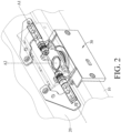
- FIG. 2 is a partial perspective view of the casing assembly 1 of the electronic device 100 according to the one embodiment of the disclosure
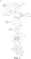
- FIG. 3 is an exploded view of a hinge assembly 30 in FIG. 2 .
- the casing assembly 1 of the electronic device 100 includes a first casing 10, a second casing 20 and a hinge assembly 30.
- the electronic device 100 is, for example, a notebook computer
- the first casing 10 is, for example, a casing of a host
- the second casing 20 is, for example, a casing of a monitor, but the disclosure is not limited thereto.
- an electronic device has two portions which are rotatable relative to each other, and the rotatable range between the two portions is required to be limited, such electronic device falls within the scope of the disclosure.
- the hinge assembly 30 includes a fixed frame 31, a shaft 32, a rotatable frame 33 and a cover 34.
- the hinge assembly 30 may further include a first washer 35, a plurality of second washers 36 and a positioning plate 37.
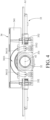
- FIG. 4 is a top view of the hinge assembly 30 in FIG. 3
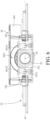
- FIG. 5 is a bottom view of the hinge assembly 30 in FIG. 3 .
- the fixed frame 31 is fixed to the first casing 10 via, for example, a fastener (not shown), such as a screw.
- the shaft 32 includes a pillar portion 321 and a flange portion 322.
- the flange portion 322 radially protrudes from the pillar portion 321.
- the pillar portion 321 of the shaft 32 is sequentially disposed through the first washer 35, the fixed frame 31 and the second washers 36, and the pillar portion 321 of the shaft 32 is rotatable relative to the fixed frame 31.
- a through hole 311 of the fixed frame 31 which the pillar portion 321 of the shaft 32 is disposed through is round hole, such that the fixed frame 31 is not fixed to the pillar portion 321 of the shaft 32, and thus the pillar portion 321 of the shaft 32 is rotatable relative to the fixed frame 31.
- first washer 35 and the second washers 36 of the hinge assembly 30 are not restricted in the disclosure and may be modified according to actual requirements.
- the positioning plate 37 is sleeved on one end of the pillar portion 321 of the shaft 32 and fixed to the pillar portion 321 of the shaft 32, such that the first washer 35, the fixed frame 31 and the second washers 36 are positioned between the flange portion 322 of the shaft 32 and the positioning plate 37.
- the positioning plate 37 is fixed to the pillar portion 321 of the shaft 32 via, for example, the cooperation of a non-round through hole 371 of the positioning plate 37 and the pillar portion 321 of the shaft 32 that match each other.
- the positioning plate 37 has an outer annular surface 372 and a curved notch 373 recessed from the outer annular surface 372.
- the fixed frame 31 has a positioning protrusion portion 312, and the positioning protrusion portion 312 is located in the curved notch 373.
- the rotatable frame 33 includes a base 331 and two rotatable components 332.
- the base 331 is sleeved on another end of the pillar portion 321 of the shaft 32, and the base 331 is fixed to the pillar portion 321 of the shaft 32.
- the base 331 is fixed to the pillar portion 321 of the shaft 32 via, for example, the cooperation of a non-round through hole 3311 of the base 331 and the pillar portion 321 of the shaft 32 that match each other.
- the rotatable components 332 are rotatably disposed on the base 331 and fixed to the second casing 20.
- a rotation axis A2 of the base 331 relative to the fixed frame 31 via the shaft 32 is perpendicular to a rotation axis A1 of the rotatable component 332 relative to the base 331.
- the second casing 20 can be turned relative to the first casing 10 about the axis A1 via the rotatable component 332.
- the second casing 20 of the monitor can be pivoted away from or close to the first casing 10 of the host.
- the second casing 20 can be turned relative to the first casing 10 about the axis A2 via the shaft 32.
- the second casing 20 of the monitor can be turned relative to the first casing 10 of the host for allowing the monitor facing toward the host or facing away from the host.
- the cover 34 is, for example, made of metal material.
- the cover 34 includes a horizontal plate 341 and a vertical plate 342.
- the horizontal plate 341 is fixed to the first casing 10 via, for example, a fastener (not shown), such as a screw.
- the horizontal plate 341 is sleeved on the shaft 32 and located between the base 331 of the rotatable frame 33 and the fixed frame 31.
- the vertical plate 342 stands on the horizontal plate 341 and fixed to the first casing 10 via, for example, a fastener, such as a screw.
- the vertical plate 342 may cover the fixed frame 31 and a part of the shaft 32. Note that the vertical plate 342 is an optional structure and may be omitted according to actual requirements.
- the base 331 of the rotatable frame 33 has a first positioning structure 3312.
- the first positioning structure 3312 is, for example, a protrusion.
- the first positioning structure 3312 is formed at a surface of the base 331 facing the horizontal plate 341.
- the horizontal plate 341 of the cover 34 has a second positioning structure 3411.
- the second positioning structure 3411 is, for example, a curved groove.
- the second positioning structure 3411 is formed at a surface of the horizontal plate 341 facing the base 331 of the rotatable frame 33.
- the first positioning structure 3312 is movably located in the second positioning structure 3411.
- the cooperation of two opposite inner surfaces 34111 and 34112 of the second positioning structure 3411 and the first positioning structure 3312 can limit a rotatable range of the shaft 32, and the cooperation of two opposite inner surfaces 3731 and 3732 of the curved notch 373 and the positioning protrusion portion 312 can also limit the rotatable range of the shaft 32.
- FIG. 6 is a top view of the hinge assembly 30 in FIG. 3 when the rotatable frame 33 of the hinge assembly 30 is rotated
- FIG. 7 is a bottom view of the hinge assembly 30 in FIG. 3 when the rotatable frame 33 of the hinge assembly 30 is rotated.
- the first positioning structure 3312 is in contact with the inner surface 34111 of the second positioning structure 3411, and the positioning protrusion portion 312 is in contact with the inner surface 3731 of the curved notch 373.
- the rotatable frame 33 can be rotated relative to the fixed frame 31 via the shaft 32 for moving the first positioning structure 3312 towards the inner surface 34112 of the second positioning structure 3411 and moving the inner surface 3732 of the curved notch 373 towards the positioning protrusion portion 312.
- the rotatable frame 33 is unable to be further rotated relative to the fixed frame 31 in the same direction.
- the rotatable frame 33 can be rotated relative to the fixed frame 31 via the shaft 32 for moving the first positioning structure 3312 towards the inner surface 34111 of the second positioning structure 3411 and moving the inner surface 3731 of the curved notch 373 towards the positioning protrusion portion 312.
- the rotatable frame 33 is unable to be further rotated relative to the fixed frame 31 in the same direction.
- the cooperation of the second positioning structure 3411 and the first positioning structure 3312 and the cooperation of the curved notch 373 and the positioning protrusion portion 312 can limit the rotatable range of the rotatable frame 33 for preventing wires connecting the host with the monitor from being damaged due to excessive twist.
- the cover 34 is fixed to the first casing 10, and the cover 34 has the second positioning structure 3411 to be cooperated with the first positioning structure 3312 of the rotatable frame 33 so as to limit the rotatable range of the rotatable frame 33. Since the cover 34 is fixed to the first casing 10 instead of the shaft 32, when the second positioning structure 3411 of the cover 34 is hit by the first positioning structure 3312, the cover 34 firmly fixed to the first casing 10 enables the second positioning structure 3411 to have sufficient strength to stop the first positioning structure 3312. Therefore, the cover 34 can almost permanently provide the effect of stopping the rotatable frame 33 so as to prevent the wires from being damaged due to excessive twist.
- the cooperation of the curved notch 373 of the positioning plate 37 and the positioning protrusion portion 312 of the fixed frame 31 can additionally help to limit the rotatable range of the rotatable frame 33.
- the positioning plate 37 and the positioning protrusion portion 312 of the fixed frame 31 are optional component and structure.
- the cover 34 made of metal material may have a stronger structural strength for permanently providing the effect of stopping the rotatable frame 33.
- the material of the cover 34 is not restricted to being metal material and may be modified to being another material having a sufficient structural strength, such as plastic material.
- the first positioning structure 3312 is a protrusion
- the second positioning structure 3411 is a groove
- the disclosure is not limited thereto; in some other embodiments, the first positioning structure may be a groove, and the second positioning structure may be a protrusion.
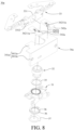
- FIG. 8 is an exploded view of a hinge assembly 30a according to another embodiment of the disclosure
- FIG. 9 is a top view of the hinge assembly 30a in FIG. 8 .
- the hinge assembly 30a of this embodiment is similar to the hinge assembly 30 with reference to FIGS. 1 to 7 .
- the hinge assembly 30a of this embodiment also includes a fixed frame 31, a shaft 32, a rotatable frame 33, a cover 34a, a first washer 35, a plurality of second washers 36 and a positioning plate 37.
- the main difference between the hinge assembly 30a and the hinge assembly 30 is the structure of the cover, and thus the following paragraphs mainly introduce the cover 34a of the hinge assembly 30a, and other components of the hinge assembly 30a can be referred to the previous paragraphs with reference to FIGS. 1 to 7 and will not be repeated introduced hereinafter.
- the cover 34a of the hinge assembly 30a includes a main part 341a and two mount parts 342a.
- the main part 341a is, for example, made of plastic material.
- the main part 341a includes a horizontal plate 3411a and a vertical plate 3412a.
- the horizontal plate 3411a is fixed to a first casing (e.g., the first casing 10 shown in FIG. 2 ), and the horizontal plate 3411a is located between the base 331 of the rotatable frame 33 and the fixed frame 31, and the vertical plate 3412a stands on the horizontal plate 3411a.
- the mount parts 342a are, for example, made of metal material.
- the mount parts 342a are mounted on the horizontal plate 3411a of the main part 341a.
- the mount parts 342a are located between the horizontal plate 3411a and the base 331 of the rotatable frame 33, and the two mount parts 342a are located at two opposite sides of the shaft 32.
- the first positioning structure 3312 of the base 331 of the rotatable frame 33 is, for example, a protrusion, and the first positioning structure 3312 is formed at a surface of the base 331 facing the two mount parts 342a.
- each of the mount parts 342a has a second positioning structure 3421a, and the second positioning structure 3421a is, for example, a positioning groove.
- the second positioning structures 3421a are respectively formed at surfaces of the mount parts 342a facing the base 331 of the rotatable frame 33.
- the first positioning structure 3312 is movable between two inner surfaces 34211a of the second positioning structures 3421a which are located opposite to each other. As a result, the cooperation of the first positioning structure 3312 and the second positioning structures 3421a can limit the rotatable range of the rotatable frame 33.
- the second positioning structures 3421a of the mount parts 342a do not form a continuous groove, such that, during the installation of the cover 34a, the rotatable frame 33 can be rotated to a position where the first positioning structure 3312 does not interfere with the mount parts 342a of the cover 34a for enabling the horizontal plate 3411a of the cover 34a can be directly sleeved on the shaft 32. Then, the rotatable frame 33 is rotated, such that the first positioning structure 3312 enters into the second positioning structure 3421a of one of the mount parts 342a.
- the cover 34a is not required to be turned to a certain angle for enabling the first positioning structure 3312 to enter into the continuous groove, thereby facilitating the installation of the cover 34a.
- the rotatable range of the rotatable frame 33 is limited by the cooperation of the first positioning structure 3312 (e.g., the protrusion) of the base 331 of the rotatable frame 33 and the second positioning structures 3421a (e.g., the positioning grooves) of the mount parts 342a of the cover 34a, but the disclosure is not limited thereto; in some other embodiments, the cover may not include the two mount parts, while the rotatable frame may further include two mount parts.
- the two mount parts are mounted on the base of the rotatable frame and each have a first positioning structure (e.g., the positioning groove), and the horizontal plate of the cover may have a second positioning structure (e.g., the protrusion).
- the cooperation of the first positioning structures of the mount parts of the rotatable frame and the second positioning structure of the horizontal plate of the cover may also limit the rotatable range of the rotatable frame.
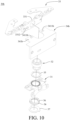
- FIG. 10 is an exploded view of a hinge assembly 30b according to still another embodiment of the disclosure
- FIG. 11 is a top view of the hinge assembly 30b in FIG. 10 .
- the hinge assembly 30b of this embodiment is similar to the hinge assembly 30 with reference to FIGS. 1 to 7 .
- the hinge assembly 30b of this embodiment also includes a fixed frame 31, a shaft 32, a rotatable frame 33, a cover 34b, a first washer 35, a plurality of second washers 36 and a positioning plate 37.
- the main difference between the hinge assembly 30b and the hinge assembly 30 is the structure of the cover, and thus the following paragraphs mainly introduce the cover 34b of the hinge assembly 30b, and other components of the hinge assembly 30b can be referred to the previous paragraphs with reference to FIGS. 1 to 7 and will not be repeated introduced hereinafter.
- a horizontal plate 341b of the cover 34b has two second positioning structures 3411b.
- the second positioning structures 3411b are, for example, stop blocks.
- the second positioning structures 3411b protrude from a surface of the horizontal plate 341b of the cover 34b facing the base 331 of the rotatable frame 33.
- the first positioning structure 3312 of the base 331 of the rotatable frame 33 is movable between the second positioning structures 3411b so as to limit the rotatable range of the rotatable frame 33.
- the rotatable range of the rotatable frame 33 is limited by the cooperation of the second positioning structures 3411b (e.g., the stop blocks) of the horizontal plate 341b of the cover 34b and the first positioning structure 3312 (e.g., the protrusion) of the base 331 of the rotatable frame 33, but the disclosure is not limited thereto; in some other embodiments, the base of the rotatable frame may have two first positioning structures (e.g., the stop blocks), and the horizontal plate of the cover may have a second positioning structure (e.g., the protrusion). As a result, the cooperation of the second positioning structure of the horizontal plate of the cover and the first positioning structures of the base of the rotatable frame may also limit the rotatable range of the rotatable frame.
- the second positioning structures 3411b e.g., the stop blocks
- the first positioning structure 3312 e.g., the protrusion
- the horizontal plate 341b of the cover 34b is not restricted to having the two second positioning structures 3411b (e.g., the stop blocks); in some other embodiments, the horizontal plate of the cover may not have the second positioning structures (e.g., the stop blocks). Instead, the fixed frame may have the two second positioning structures (e.g., the stop blocks).
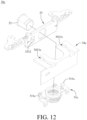
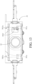
- FIGS. 12 and 13 FIG. 12 is an exploded view of a hinge assembly 30c according to yet another embodiment of the disclosure, and FIG. 13 is a top view of the hinge assembly 30c in FIG. 12 .
- the hinge assembly 30c of this embodiment is similar to the hinge assembly 30b with reference to FIGS. 10 and 11 , the main different between them is that the structures of the cover and fixed frame, and thus the following paragraphs mainly introduce a cover 34c and a fixed frame 31c of the hinge assembly 30c, and other components of the hinge assembly 30c will not be repeatedly introduced hereinafter.
- the cover 34c has two guide grooves 3411c, and the guide grooves 3411c are located around the shaft 32.
- the fixed frame 31c has two second positioning structures 311c (e.g., the stop blocks), and the second positioning structures 311c are respectively located in the guide grooves 3411c.
- the first positioning structure 3312 (e.g., the protrusion) of the rotatable frame 33 is movable between the guide grooves 3411c so as to be cooperated with the second positioning structures 311c of the fixed frame 31c for limiting the rotatable range of the rotatable frame 33.
- the rotatable range of the rotatable frame 33 is limited by the cooperation of the second positioning structures 311c (e.g., the stop blocks) of the fixed frame 31c and the first positioning structure 3312 (e.g., the protrusion) of the rotatable frame 33, but the disclosure is not limited thereto; in some other embodiments, the rotatable frame may have two first positioning structures (e.g., the stop blocks), and the fixed frame may have a second positioning structure (e.g., the protrusion). As a result, the cooperation of the second positioning structure of the fixed frame and the first positioning structures of the rotatable frame may also limit the rotatable range of the rotatable frame.
- the second positioning structures 311c e.g., the stop blocks
- the first positioning structure 3312 e.g., the protrusion
- the quantity and the type of the second positioning structures 311c of the fixed frame 31c are not restricted in the disclosure; in some other embodiments, the fixed frame may have single one second positioning structure, the second positioning structure may be a groove, and the guide grooves of the cover may be through holes.
- the first positioning structure (e.g., the protrusion) of the rotatable frame may be disposed through one of the guide grooves of the cover and movably located in the second positioning structure of the fixed frame, such that two opposite inner surfaces of the second positioning structure of the fixed frame can limit the rotatable range of the rotatable frame.
- the cover is fixed to the first casing, and the fixed frame or the cover has the second positioning structure to be cooperated with the first positioning structure of the rotatable frame, such that the rotatable range of the rotatable frame can be limited. Since the fixed frame and the cover is fixed to the first casing instead of the shaft, when the second positioning structure of the fixed frame or the cover is hit by the first positioning structure, the fixed frame or the cover firmly fixed to the first casing enables the second positioning structure to have sufficient strength to stop the first positioning structure. Therefore, the fixed frame or the cover can permanently provide the effect of stopping the rotatable frame so as to prevent the wires from being damaged due to excessive twist.
- the cooperation of the curved notch of the positioning plate and the positioning protrusion portion of the fixed frame can additionally help to limit the rotatable range of the rotatable frame.
Landscapes
- Engineering & Computer Science (AREA)
- Theoretical Computer Science (AREA)
- Computer Hardware Design (AREA)
- Physics & Mathematics (AREA)
- Human Computer Interaction (AREA)
- General Engineering & Computer Science (AREA)
- General Physics & Mathematics (AREA)
- Mathematical Physics (AREA)
- Signal Processing (AREA)
- Pivots And Pivotal Connections (AREA)
- Casings For Electric Apparatus (AREA)
Abstract
Description
- The disclosure relates to a hinge assembly and a casing assembly for electronic device including the same.
- As technology develops and progresses, twistable notebook computers are developed. In a twistable notebook computer, after a monitor of the notebook computer is pivoted away from a host of the notebook computer (i.e., the notebook computer is opened), the monitor can be turned right or left relative to the host, such that the monitor can face the user in front of the notebook computer or face the left-hand or right hand side of the user in front of the notebook computer.
- In order to prevent the monitor from being improperly closed and prevent wires connecting the monitor and the host from being damaged due to the excessive turn of the monitor relative to the host, the notebook manufacturer may provide a stopper fixed on a shaft located between the monitor and the host. However, the fixation strength of the stopper on the shaft is weak, such that after the monitor has been turned many times, the stopper may gradually be movable relative to the shaft, causing the stopper failure. Therefore, how to solve the aforementioned issue is one of the crucial topics in this field.
- The disclosure provides a hinge assembly and a casing assembly for an electronic device which are capable of maintaining the effect of preventing the monitor from being overly turned so as to prevent the wires from being damaged due to overly twisted.
- One embodiment of the disclosure provides a hinge assembly. The hinge assembly includes a fixed frame, a shaft, a rotatable frame and a cover. The shaft is rotatably disposed on the fixed frame. The rotatable frame is fixed to the shaft, and the rotatable frame has a first positioning structure. The cover is at least partially located between the rotatable frame and the fixed frame and sleeved on the shaft. The fixed frame or the cover has at least one second positioning structure, and the first positioning structure and the at least one second positioning structure are cooperated with each other so as to limit a rotatable range of the rotatable frame.
- Another embodiment of the disclosure provides a casing assembly for electronic device. The casing assembly includes a first casing, a second casing and a hinge assembly. The hinge assembly includes a fixed frame, a shaft, a rotatable frame and a cover. The fixed frame is fixed to the first casing. The shaft is rotatably disposed on the fixed frame. The rotatable frame is fixed to the shaft and the second casing, and the rotatable frame has a first positioning structure. The cover is fixed to the first casing. The fixed frame or the cover has at least one second positioning structure, and the first positioning structure and the at least one second positioning structure are cooperated with each other so as to limit a rotatable range of the rotatable frame.
- According to the hinge assembly and the casing assembly for the electronic device as described above, the cover is fixed to the first casing, and the fixed frame or the cover has the second positioning structure to be cooperated with the first positioning structure of the rotatable frame, such that the rotatable range of the rotatable frame can be limited. Since the fixed frame and the cover is fixed to the first casing instead of the shaft, when the second positioning structure of the fixed frame or the cover is hit by the first positioning structure, the fixed frame or the cover firmly fixed to the first casing enables the second positioning structure to have sufficient strength to stop the first positioning structure. Therefore, the fixed frame or the cover can permanently provide the effect of stopping the rotatable frame so as to prevent the wires from being damaged due to excessive twist.
- The present disclosure will become better understood from the detailed description given herein below and the accompanying drawings which are given by way of illustration only and thus are not intending to limit the present disclosure and wherein:
-
FIG. 1 is a perspective view of an electronic device including a casing assembly according to one embodiment of the disclosure; -
FIG. 2 is a partial perspective view of the casing assembly of the electronic device according to the one embodiment of the disclosure; -
FIG. 3 is an exploded view of a hinge assembly inFIG. 2 ; -
FIG. 4 is a top view of the hinge assembly inFIG. 3 ; -
FIG. 5 is a bottom view of the hinge assembly inFIG. 3 ; -
FIG. 6 is a top view of the hinge assembly inFIG. 3 when a rotatable frame of the hinge assembly is rotated; -
FIG. 7 is a bottom view of the hinge assembly inFIG. 3 when the rotatable frame of the hinge assembly is rotated; -
FIG. 8 is an exploded view of a hinge assembly according to another embodiment of the disclosure; -
FIG. 9 is a top view of the hinge assembly inFIG. 8 ; -
FIG. 10 is an exploded view of a hinge assembly according to still another embodiment of the disclosure; -
FIG. 11 is a top view of the hinge assembly inFIG. 10 ; -
FIG. 12 is an exploded view of a hinge assembly according to yet another embodiment of the disclosure; and -
FIG. 13 is a top view of the hinge assembly inFIG. 12 . - In the following detailed description, for purposes of explanation, numerous specific details are set forth in order to provide a thorough understanding of the disclosed embodiments. It will be apparent, however, that one or more embodiments may be practiced without these specific details. In other instances, well-known structures and devices are schematically shown in order to simplify the drawing.
- In addition, the terms used in the present disclosure, such as technical and scientific terms, have its own meanings and can be comprehended by those skilled in the art, unless the terms are additionally defined in the present disclosure. That is, the terms used in the following paragraphs should be read on the meaning commonly used in the related fields and will not be overly explained, unless the terms have a specific meaning in the present disclosure.
- Referring to
FIGS. 1 to 3 ,FIG. 1 is a perspective view of anelectronic device 100 including acasing assembly 1 according to one embodiment of the disclosure,FIG. 2 is a partial perspective view of thecasing assembly 1 of theelectronic device 100 according to the one embodiment of the disclosure, andFIG. 3 is an exploded view of ahinge assembly 30 inFIG. 2 . - In this embodiment, the
casing assembly 1 of theelectronic device 100 includes afirst casing 10, asecond casing 20 and ahinge assembly 30. Theelectronic device 100 is, for example, a notebook computer, thefirst casing 10 is, for example, a casing of a host, and thesecond casing 20 is, for example, a casing of a monitor, but the disclosure is not limited thereto. As long as an electronic device has two portions which are rotatable relative to each other, and the rotatable range between the two portions is required to be limited, such electronic device falls within the scope of the disclosure. - The
hinge assembly 30 includes afixed frame 31, ashaft 32, arotatable frame 33 and acover 34. In addition, thehinge assembly 30 may further include afirst washer 35, a plurality ofsecond washers 36 and apositioning plate 37. - Then, referring to
FIGS. 2 to 5 ,FIG. 4 is a top view of thehinge assembly 30 inFIG. 3 , andFIG. 5 is a bottom view of thehinge assembly 30 inFIG. 3 . - The
fixed frame 31 is fixed to thefirst casing 10 via, for example, a fastener (not shown), such as a screw. - The
shaft 32 includes a pillar portion 321 and a flange portion 322. The flange portion 322 radially protrudes from the pillar portion 321. The pillar portion 321 of theshaft 32 is sequentially disposed through thefirst washer 35, thefixed frame 31 and thesecond washers 36, and the pillar portion 321 of theshaft 32 is rotatable relative to thefixed frame 31. In this embodiment, athrough hole 311 of thefixed frame 31 which the pillar portion 321 of theshaft 32 is disposed through is round hole, such that thefixed frame 31 is not fixed to the pillar portion 321 of theshaft 32, and thus the pillar portion 321 of theshaft 32 is rotatable relative to thefixed frame 31. - Note that the quantities of the
first washer 35 and thesecond washers 36 of thehinge assembly 30 are not restricted in the disclosure and may be modified according to actual requirements. - The
positioning plate 37 is sleeved on one end of the pillar portion 321 of theshaft 32 and fixed to the pillar portion 321 of theshaft 32, such that thefirst washer 35, thefixed frame 31 and thesecond washers 36 are positioned between the flange portion 322 of theshaft 32 and thepositioning plate 37. In this embodiment, thepositioning plate 37 is fixed to the pillar portion 321 of theshaft 32 via, for example, the cooperation of a non-round throughhole 371 of thepositioning plate 37 and the pillar portion 321 of theshaft 32 that match each other. - In this embodiment, the
positioning plate 37 has an outerannular surface 372 and acurved notch 373 recessed from the outerannular surface 372. Thefixed frame 31 has apositioning protrusion portion 312, and thepositioning protrusion portion 312 is located in thecurved notch 373. - The
rotatable frame 33 includes abase 331 and tworotatable components 332. Thebase 331 is sleeved on another end of the pillar portion 321 of theshaft 32, and thebase 331 is fixed to the pillar portion 321 of theshaft 32. In this embodiment, thebase 331 is fixed to the pillar portion 321 of theshaft 32 via, for example, the cooperation of a non-round throughhole 3311 of thebase 331 and the pillar portion 321 of theshaft 32 that match each other. Therotatable components 332 are rotatably disposed on thebase 331 and fixed to thesecond casing 20. A rotation axis A2 of the base 331 relative to the fixedframe 31 via theshaft 32 is perpendicular to a rotation axis A1 of therotatable component 332 relative to thebase 331. As a result, thesecond casing 20 can be turned relative to thefirst casing 10 about the axis A1 via therotatable component 332. For example, thesecond casing 20 of the monitor can be pivoted away from or close to thefirst casing 10 of the host. Moreover, thesecond casing 20 can be turned relative to thefirst casing 10 about the axis A2 via theshaft 32. For example, thesecond casing 20 of the monitor can be turned relative to thefirst casing 10 of the host for allowing the monitor facing toward the host or facing away from the host. - The
cover 34 is, for example, made of metal material. Thecover 34 includes ahorizontal plate 341 and avertical plate 342. Thehorizontal plate 341 is fixed to thefirst casing 10 via, for example, a fastener (not shown), such as a screw. Thehorizontal plate 341 is sleeved on theshaft 32 and located between the base 331 of therotatable frame 33 and the fixedframe 31. Thevertical plate 342 stands on thehorizontal plate 341 and fixed to thefirst casing 10 via, for example, a fastener, such as a screw. Thevertical plate 342 may cover the fixedframe 31 and a part of theshaft 32. Note that thevertical plate 342 is an optional structure and may be omitted according to actual requirements. - In this embodiment, the
base 331 of therotatable frame 33 has afirst positioning structure 3312. Thefirst positioning structure 3312 is, for example, a protrusion. Thefirst positioning structure 3312 is formed at a surface of the base 331 facing thehorizontal plate 341. In addition, thehorizontal plate 341 of thecover 34 has asecond positioning structure 3411. Thesecond positioning structure 3411 is, for example, a curved groove. Thesecond positioning structure 3411 is formed at a surface of thehorizontal plate 341 facing thebase 331 of therotatable frame 33. Thefirst positioning structure 3312 is movably located in thesecond positioning structure 3411. - In this embodiment, the cooperation of two opposite
inner surfaces second positioning structure 3411 and thefirst positioning structure 3312 can limit a rotatable range of theshaft 32, and the cooperation of two oppositeinner surfaces curved notch 373 and thepositioning protrusion portion 312 can also limit the rotatable range of theshaft 32. - Specifically, referring to
FIGS. 4 to 7 ,FIG. 6 is a top view of thehinge assembly 30 inFIG. 3 when therotatable frame 33 of thehinge assembly 30 is rotated, andFIG. 7 is a bottom view of thehinge assembly 30 inFIG. 3 when therotatable frame 33 of thehinge assembly 30 is rotated. - As shown in
FIGS. 4 and5 , thefirst positioning structure 3312 is in contact with theinner surface 34111 of thesecond positioning structure 3411, and thepositioning protrusion portion 312 is in contact with theinner surface 3731 of thecurved notch 373. As shown inFIGS. 6 and7 , therotatable frame 33 can be rotated relative to the fixedframe 31 via theshaft 32 for moving thefirst positioning structure 3312 towards theinner surface 34112 of thesecond positioning structure 3411 and moving theinner surface 3732 of thecurved notch 373 towards the positioningprotrusion portion 312. Once thefirst positioning structure 3312 is in contact with theinner surface 34112 of thesecond positioning structure 3411, and theinner surface 3732 of thecurved notch 373 is in contact with thepositioning protrusion portion 312, therotatable frame 33 is unable to be further rotated relative to the fixedframe 31 in the same direction. - Similarly, the
rotatable frame 33 can be rotated relative to the fixedframe 31 via theshaft 32 for moving thefirst positioning structure 3312 towards theinner surface 34111 of thesecond positioning structure 3411 and moving theinner surface 3731 of thecurved notch 373 towards the positioningprotrusion portion 312. Once thefirst positioning structure 3312 is in contact with theinner surface 34111 of thesecond positioning structure 3411, and theinner surface 3731 of thecurved notch 373 is in contact with thepositioning protrusion portion 312, therotatable frame 33 is unable to be further rotated relative to the fixedframe 31 in the same direction. - As a result, the cooperation of the
second positioning structure 3411 and thefirst positioning structure 3312 and the cooperation of thecurved notch 373 and thepositioning protrusion portion 312 can limit the rotatable range of therotatable frame 33 for preventing wires connecting the host with the monitor from being damaged due to excessive twist. - In this embodiment, the
cover 34 is fixed to thefirst casing 10, and thecover 34 has thesecond positioning structure 3411 to be cooperated with thefirst positioning structure 3312 of therotatable frame 33 so as to limit the rotatable range of therotatable frame 33. Since thecover 34 is fixed to thefirst casing 10 instead of theshaft 32, when thesecond positioning structure 3411 of thecover 34 is hit by thefirst positioning structure 3312, thecover 34 firmly fixed to thefirst casing 10 enables thesecond positioning structure 3411 to have sufficient strength to stop thefirst positioning structure 3312. Therefore, thecover 34 can almost permanently provide the effect of stopping therotatable frame 33 so as to prevent the wires from being damaged due to excessive twist. - In addition, the cooperation of the
curved notch 373 of thepositioning plate 37 and thepositioning protrusion portion 312 of the fixedframe 31 can additionally help to limit the rotatable range of therotatable frame 33. Note that thepositioning plate 37 and thepositioning protrusion portion 312 of the fixedframe 31 are optional component and structure. When the cooperation of the first positioning structure of the rotatable frame and the second positioning structure of the cover are already capable of sufficiently limiting the rotatable range of the rotatable frame, the positioning plate and the positioning protrusion portion of the fixed frame can be omitted. - On the other hand, the
cover 34 made of metal material may have a stronger structural strength for permanently providing the effect of stopping therotatable frame 33. Note that the material of thecover 34 is not restricted to being metal material and may be modified to being another material having a sufficient structural strength, such as plastic material. - In this embodiment, the
first positioning structure 3312 is a protrusion, and thesecond positioning structure 3411 is a groove, but the disclosure is not limited thereto; in some other embodiments, the first positioning structure may be a groove, and the second positioning structure may be a protrusion. - Then, referring to
FIGS. 8 and9 ,FIG. 8 is an exploded view of ahinge assembly 30a according to another embodiment of the disclosure, andFIG. 9 is a top view of thehinge assembly 30a inFIG. 8 . - The
hinge assembly 30a of this embodiment is similar to thehinge assembly 30 with reference toFIGS. 1 to 7 . Thehinge assembly 30a of this embodiment also includes a fixedframe 31, ashaft 32, arotatable frame 33, acover 34a, afirst washer 35, a plurality ofsecond washers 36 and apositioning plate 37. The main difference between thehinge assembly 30a and thehinge assembly 30 is the structure of the cover, and thus the following paragraphs mainly introduce thecover 34a of thehinge assembly 30a, and other components of thehinge assembly 30a can be referred to the previous paragraphs with reference toFIGS. 1 to 7 and will not be repeated introduced hereinafter. - In this embodiment, the
cover 34a of thehinge assembly 30a includes amain part 341a and twomount parts 342a. Themain part 341a is, for example, made of plastic material. Themain part 341a includes ahorizontal plate 3411a and avertical plate 3412a. Thehorizontal plate 3411a is fixed to a first casing (e.g., thefirst casing 10 shown inFIG. 2 ), and thehorizontal plate 3411a is located between the base 331 of therotatable frame 33 and the fixedframe 31, and thevertical plate 3412a stands on thehorizontal plate 3411a. Themount parts 342a are, for example, made of metal material. Themount parts 342a are mounted on thehorizontal plate 3411a of themain part 341a. Themount parts 342a are located between thehorizontal plate 3411a and thebase 331 of therotatable frame 33, and the twomount parts 342a are located at two opposite sides of theshaft 32. - In this embodiment, the
first positioning structure 3312 of thebase 331 of therotatable frame 33 is, for example, a protrusion, and thefirst positioning structure 3312 is formed at a surface of the base 331 facing the twomount parts 342a. In addition, each of themount parts 342a has asecond positioning structure 3421a, and thesecond positioning structure 3421a is, for example, a positioning groove. Thesecond positioning structures 3421a are respectively formed at surfaces of themount parts 342a facing thebase 331 of therotatable frame 33. Thefirst positioning structure 3312 is movable between twoinner surfaces 34211a of thesecond positioning structures 3421a which are located opposite to each other. As a result, the cooperation of thefirst positioning structure 3312 and thesecond positioning structures 3421a can limit the rotatable range of therotatable frame 33. - In this embodiment, the
second positioning structures 3421a of themount parts 342a do not form a continuous groove, such that, during the installation of thecover 34a, therotatable frame 33 can be rotated to a position where thefirst positioning structure 3312 does not interfere with themount parts 342a of thecover 34a for enabling thehorizontal plate 3411a of thecover 34a can be directly sleeved on theshaft 32. Then, therotatable frame 33 is rotated, such that thefirst positioning structure 3312 enters into thesecond positioning structure 3421a of one of themount parts 342a. In other words, since thesecond positioning structures 3421a of themount parts 342a do not form a continuous groove, during the installation of thecover 34a, thecover 34a is not required to be turned to a certain angle for enabling thefirst positioning structure 3312 to enter into the continuous groove, thereby facilitating the installation of thecover 34a. - In this embodiment, the rotatable range of the
rotatable frame 33 is limited by the cooperation of the first positioning structure 3312 (e.g., the protrusion) of thebase 331 of therotatable frame 33 and thesecond positioning structures 3421a (e.g., the positioning grooves) of themount parts 342a of thecover 34a, but the disclosure is not limited thereto; in some other embodiments, the cover may not include the two mount parts, while the rotatable frame may further include two mount parts. The two mount parts are mounted on the base of the rotatable frame and each have a first positioning structure (e.g., the positioning groove), and the horizontal plate of the cover may have a second positioning structure (e.g., the protrusion). As a result, the cooperation of the first positioning structures of the mount parts of the rotatable frame and the second positioning structure of the horizontal plate of the cover may also limit the rotatable range of the rotatable frame. - Then, referring to
FIGS. 10 and11 ,FIG. 10 is an exploded view of ahinge assembly 30b according to still another embodiment of the disclosure, andFIG. 11 is a top view of thehinge assembly 30b inFIG. 10 . - The
hinge assembly 30b of this embodiment is similar to thehinge assembly 30 with reference toFIGS. 1 to 7 . Thehinge assembly 30b of this embodiment also includes a fixedframe 31, ashaft 32, arotatable frame 33, acover 34b, afirst washer 35, a plurality ofsecond washers 36 and apositioning plate 37. The main difference between thehinge assembly 30b and thehinge assembly 30 is the structure of the cover, and thus the following paragraphs mainly introduce thecover 34b of thehinge assembly 30b, and other components of thehinge assembly 30b can be referred to the previous paragraphs with reference toFIGS. 1 to 7 and will not be repeated introduced hereinafter. - In this embodiment, a
horizontal plate 341b of thecover 34b has twosecond positioning structures 3411b. Thesecond positioning structures 3411b are, for example, stop blocks. Thesecond positioning structures 3411b protrude from a surface of thehorizontal plate 341b of thecover 34b facing thebase 331 of therotatable frame 33. Thefirst positioning structure 3312 of thebase 331 of therotatable frame 33 is movable between thesecond positioning structures 3411b so as to limit the rotatable range of therotatable frame 33. - In this embodiment, the rotatable range of the
rotatable frame 33 is limited by the cooperation of thesecond positioning structures 3411b (e.g., the stop blocks) of thehorizontal plate 341b of thecover 34b and the first positioning structure 3312 (e.g., the protrusion) of thebase 331 of therotatable frame 33, but the disclosure is not limited thereto; in some other embodiments, the base of the rotatable frame may have two first positioning structures (e.g., the stop blocks), and the horizontal plate of the cover may have a second positioning structure (e.g., the protrusion). As a result, the cooperation of the second positioning structure of the horizontal plate of the cover and the first positioning structures of the base of the rotatable frame may also limit the rotatable range of the rotatable frame. - Note that the
horizontal plate 341b of thecover 34b is not restricted to having the twosecond positioning structures 3411b (e.g., the stop blocks); in some other embodiments, the horizontal plate of the cover may not have the second positioning structures (e.g., the stop blocks). Instead, the fixed frame may have the two second positioning structures (e.g., the stop blocks). For example, referring toFIGS. 12 and13 ,FIG. 12 is an exploded view of ahinge assembly 30c according to yet another embodiment of the disclosure, andFIG. 13 is a top view of thehinge assembly 30c inFIG. 12 . - The
hinge assembly 30c of this embodiment is similar to thehinge assembly 30b with reference toFIGS. 10 and11 , the main different between them is that the structures of the cover and fixed frame, and thus the following paragraphs mainly introduce acover 34c and a fixedframe 31c of thehinge assembly 30c, and other components of thehinge assembly 30c will not be repeatedly introduced hereinafter. - In this embodiment, the
cover 34c has twoguide grooves 3411c, and theguide grooves 3411c are located around theshaft 32. The fixedframe 31c has twosecond positioning structures 311c (e.g., the stop blocks), and thesecond positioning structures 311c are respectively located in theguide grooves 3411c. The first positioning structure 3312 (e.g., the protrusion) of therotatable frame 33 is movable between theguide grooves 3411c so as to be cooperated with thesecond positioning structures 311c of the fixedframe 31c for limiting the rotatable range of therotatable frame 33. - In this embodiment, the rotatable range of the
rotatable frame 33 is limited by the cooperation of thesecond positioning structures 311c (e.g., the stop blocks) of the fixedframe 31c and the first positioning structure 3312 (e.g., the protrusion) of therotatable frame 33, but the disclosure is not limited thereto; in some other embodiments, the rotatable frame may have two first positioning structures (e.g., the stop blocks), and the fixed frame may have a second positioning structure (e.g., the protrusion). As a result, the cooperation of the second positioning structure of the fixed frame and the first positioning structures of the rotatable frame may also limit the rotatable range of the rotatable frame. - In addition, the quantity and the type of the
second positioning structures 311c of the fixedframe 31c are not restricted in the disclosure; in some other embodiments, the fixed frame may have single one second positioning structure, the second positioning structure may be a groove, and the guide grooves of the cover may be through holes. As a result, the first positioning structure (e.g., the protrusion) of the rotatable frame may be disposed through one of the guide grooves of the cover and movably located in the second positioning structure of the fixed frame, such that two opposite inner surfaces of the second positioning structure of the fixed frame can limit the rotatable range of the rotatable frame. - According to the hinge assemblies and the casing assembly for the electronic device as described above, the cover is fixed to the first casing, and the fixed frame or the cover has the second positioning structure to be cooperated with the first positioning structure of the rotatable frame, such that the rotatable range of the rotatable frame can be limited. Since the fixed frame and the cover is fixed to the first casing instead of the shaft, when the second positioning structure of the fixed frame or the cover is hit by the first positioning structure, the fixed frame or the cover firmly fixed to the first casing enables the second positioning structure to have sufficient strength to stop the first positioning structure. Therefore, the fixed frame or the cover can permanently provide the effect of stopping the rotatable frame so as to prevent the wires from being damaged due to excessive twist.
- In addition, the cooperation of the curved notch of the positioning plate and the positioning protrusion portion of the fixed frame can additionally help to limit the rotatable range of the rotatable frame.
- It will be apparent to those skilled in the art that various modifications and variations can be made to the present disclosure. It is intended that the specification and examples be considered as exemplary embodiments only, with a scope of the disclosure being indicated by the following claims and their equivalents.
Claims (15)
- A hinge assembly (30, 30a, 30b, 30c), comprising:a fixed frame (31, 31c);a shaft (32), rotatably disposed on the fixed frame (31, 31c);a rotatable frame (33), fixed to the shaft (32), wherein the rotatable frame (33) has a first positioning structure (3312); anda cover (34, 34a, 34b, 34c), at least partially located between the rotatable frame (33) and the fixed frame (31, 31c) and sleeved on the shaft (32);wherein the fixed frame (31c) or the cover (34, 34a, 34b) has at least one second positioning structure (311c, 3411, 3411b, 3421a), and the first positioning structure (3312) and the at least one second positioning structure (311c, 3411, 3411b, 3421a) are cooperated with each other so as to limit a rotatable range of the rotatable frame (33).
- The hinge assembly (30, 30b) according to claim 1, wherein the cover (34, 34b) comprises a horizontal plate (341, 341b), the horizontal plate (341, 341b) is located between the rotatable frame (33) and the fixed frame (31), the first positioning structure (3312) is formed at a surface of the rotatable frame (33) facing the horizontal plate (341, 341b), and the at least one second positioning structure (3411, 3411b) is formed at a surface of the horizontal plate (341, 341b) facing the rotatable frame (33).
- The hinge assembly (30, 30a) according to claim 1, wherein the first positioning structure (3312) is a protrusion, the at least one second positioning structure (3411, 3421a) is a groove, and the first positioning structure (3312) is movably located in the at least one second positioning structure (3411, 3421a).
- The hinge assembly (30b, 30c) according to claim 1, wherein the first positioning structure (3312) is a protrusion, the at least one second positioning structure (3411b, 311c) is a stop block, the at least one second positioning structure (3411b, 311c) comprises two second positioning structures (3411b, 311c), and the first positioning structure (3312) is movable between the two second positioning structures (3411b, 311c).
- The hinge assembly (30c) according to claim 4, wherein the cover (34c) has two guide grooves (3411c), the two guide grooves (3411c) are located around of the shaft (32), the fixed frame (31c) has the two second positioning structures (311c), the two second positioning structures (311c) are respectively located in the guide grooves (3411c), the first positioning structure (3312) is movable between the two guide grooves (3411c) so as to be cooperated with the two second positioning structures (311c) for limiting the rotatable range of the rotatable frame (33).
- The hinge assembly (30, 30a, 30b) according to claim 1, further comprising a positioning plate (37), wherein the positioning plate (37) is sleeved on and fixed to the shaft (32), the positioning plate (37) has an outer annular surface (372) and a curved notch (373) recessed from the outer annular surface (372), the fixed frame (31) has a positioning protrusion portion (312), and the positioning protrusion portion (312) is located in the curved notch (373).
- A casing assembly (1) for electronic device (100), comprising:a first casing (10);a second casing (20); anda hinge assembly (30, 30a, 30b, 30c), comprising:a fixed frame (31, 31c), fixed to the first casing (10);a shaft (32), rotatably disposed on the fixed frame (31, 31c);a rotatable frame (33), fixed to the shaft (32) and the second casing (20), wherein the rotatable frame (33) has a first positioning structure (3312); anda cover (34, 34a, 34b, 34c), fixed to the first casing (10);wherein the fixed frame (31c) or the cover (34, 34a, 34b) has at least one second positioning structure (311c, 3411, 3411b, 3421a), and the first positioning structure (3312) and the at least one second positioning structure (311c, 3411, 3411b, 3421a) are cooperated with each other so as to limit a rotatable range of the rotatable frame (33).
- The casing assembly (1) according to claim 7, wherein the cover (34, 34b) comprises a horizontal plate (341, 341b) and a vertical plate (342), the horizontal plate (341, 341b) is fixed to the first casing (10), the vertical plate (342) stands on the horizontal plate (341, 341b), the horizontal plate (341, 341b) is located between the rotatable frame (33) and the fixed frame (31), the first positioning structure (3312) is formed at a surface of the rotatable frame (33) facing the horizontal plate (341, 341b), and the at least one second positioning structure (3411, 3411b) is formed at a surface of the horizontal plate (341, 341b) facing the rotatable frame (33).
- The casing assembly (1) according to claim 7, wherein the first positioning structure (3312) is a protrusion, the at least one second positioning structure (3411, 3421a) is a curved groove, and the first positioning structure (3312) is movably located in the at least one second positioning structure (3411, 3421a).
- The casing assembly (1) according to claim 7, wherein the cover (34, 34b, 34c) is made of metal material or plastic material.
- The casing assembly (1) according to claim 7, wherein the cover (34a) comprises a main part (341a) and two mount parts (342a), the main part (341a) is fixed to the first casing (10), the two mount parts (342a) are mounted on the main part (341a), the at least one second positioning structure (3421a) comprises two second positioning structures (3421a), the two second positioning structures (3421a) are respectively located at the two mount parts (342a), and the first positioning structure (3312) is movable between the two second positioning structures (3421a).
- The casing assembly (1) according to claim 11, wherein the main part (341a) of the cover (34a) comprises a horizontal plate (3411a) and a vertical plate (3412a), the horizontal plate (3411a) is fixed to the first casing (10), the vertical plate (3412a) stands on the horizontal plate (3411a), the horizontal plate (3411a) is located between the rotatable frame (33) and the fixed frame (31), the two mount parts (342a) are located between the horizontal plate (3411a) and the rotatable frame (33), the first positioning structure (3312) is formed at a surface of the rotatable frame (33) facing the two mount parts (342a), and the two second positioning structures (3421a) are respectively formed at surfaces of the two mount parts (342a) facing the rotatable frame (33).
- The casing assembly (1) according to claim 11, wherein the first positioning structure (3312) is a protrusion, and the two second positioning structures (3421a) are positioning grooves.
- The casing assembly (1) according to claim 11, wherein the main part (341a) is made of plastic material, and the two mount parts (342a) are made of metal material.
- The casing assembly (1) according to claim 7, wherein the rotatable frame (33) comprises a base (331) and two rotatable components (332), the base (331) is fixed to the shaft (32), the two rotatable components (332) are rotatably disposed on the base (331) and fixed to the second casing (20), and a rotation axis (A1) of the two rotatable components (332) relative to the base (331) is perpendicular to a rotation axis (A1) of the base (331) relative to the fixed frame (31) via the shaft (32).
Applications Claiming Priority (1)
| Application Number | Priority Date | Filing Date | Title |
|---|---|---|---|
| CN202310073077.0A CN118363426A (en) | 2023-01-18 | 2023-01-18 | Hinge assembly and casing assembly of electronic device |
Publications (2)
| Publication Number | Publication Date |
|---|---|
| EP4404027A1 true EP4404027A1 (en) | 2024-07-24 |
| EP4404027B1 EP4404027B1 (en) | 2025-01-29 |
Family
ID=86609545
Family Applications (1)
| Application Number | Title | Priority Date | Filing Date |
|---|---|---|---|
| EP23175991.1A Active EP4404027B1 (en) | 2023-01-18 | 2023-05-30 | Hinge assembly and casing assembly for electronic device |
Country Status (4)
| Country | Link |
|---|---|
| US (2) | US12468339B2 (en) |
| EP (1) | EP4404027B1 (en) |
| CN (1) | CN118363426A (en) |
| AU (1) | AU2023203389B2 (en) |
Families Citing this family (1)
| Publication number | Priority date | Publication date | Assignee | Title |
|---|---|---|---|---|
| USD1075747S1 (en) * | 2023-11-16 | 2025-05-20 | Super Laptop Computer Limited | Laptop |
Citations (3)
| Publication number | Priority date | Publication date | Assignee | Title |
|---|---|---|---|---|
| US20080078061A1 (en) * | 2006-07-14 | 2008-04-03 | Hon Hai Precision Industry Co., Ltd. | Hinge assembly for foldable electronic device |
| US20080120805A1 (en) * | 2006-11-28 | 2008-05-29 | Sinher Technology Inc. | Rotating hinge with an elevating structure |
| US20130162128A1 (en) * | 2011-12-23 | 2013-06-27 | Wistron Corporation | Biaxial pivoting mechanism and electronic device thereof |
Family Cites Families (12)
| Publication number | Priority date | Publication date | Assignee | Title |
|---|---|---|---|---|
| US7308733B2 (en) * | 2003-05-15 | 2007-12-18 | Lg Electronics Inc. | Swivel hinge assembly and electronic device having the same |
| US7133280B2 (en) * | 2004-03-22 | 2006-11-07 | Gateway Inc. | Multiaxial hinge assembly with rotational direction indicator |
| TWM279898U (en) * | 2005-06-21 | 2005-11-01 | Shin Zu Shing Co Ltd | Laptop computer screen rotating device |
| TWI323399B (en) | 2006-07-21 | 2010-04-11 | Hon Hai Prec Ind Co Ltd | Hinge structure |
| CN101625009B (en) | 2008-07-08 | 2012-07-18 | 鸿富锦精密工业(深圳)有限公司 | Hinge structure |
| TWI380767B (en) | 2008-09-05 | 2012-12-21 | Hon Hai Prec Ind Co Ltd | Hinge assembly |
| CN102840220A (en) | 2011-06-21 | 2012-12-26 | 鸿富锦精密工业(深圳)有限公司 | hinge structure |
| JP2018072934A (en) * | 2016-10-25 | 2018-05-10 | 富士通株式会社 | Terminal device |
| TWI688323B (en) | 2017-11-22 | 2020-03-11 | 仁寶電腦工業股份有限公司 | Dual axes hinge and electronic device |
| CN109654114B (en) | 2019-01-21 | 2024-05-28 | 昆山玮硕恒基智能科技股份有限公司 | Hinge linkage mechanism |
| TWI715440B (en) | 2020-02-13 | 2021-01-01 | 宏碁股份有限公司 | Hinge module and portable electronic device |
| TWM614529U (en) | 2021-04-23 | 2021-07-11 | 新日興股份有限公司 | Hinge and electronic device using the same |
-
2023
- 2023-01-18 CN CN202310073077.0A patent/CN118363426A/en active Pending
- 2023-05-02 US US18/142,084 patent/US12468339B2/en active Active
- 2023-05-30 EP EP23175991.1A patent/EP4404027B1/en active Active
- 2023-05-31 AU AU2023203389A patent/AU2023203389B2/en active Active
-
2025
- 2025-10-15 US US19/358,902 patent/US20260037027A1/en active Pending
Patent Citations (3)
| Publication number | Priority date | Publication date | Assignee | Title |
|---|---|---|---|---|
| US20080078061A1 (en) * | 2006-07-14 | 2008-04-03 | Hon Hai Precision Industry Co., Ltd. | Hinge assembly for foldable electronic device |
| US20080120805A1 (en) * | 2006-11-28 | 2008-05-29 | Sinher Technology Inc. | Rotating hinge with an elevating structure |
| US20130162128A1 (en) * | 2011-12-23 | 2013-06-27 | Wistron Corporation | Biaxial pivoting mechanism and electronic device thereof |
Also Published As
| Publication number | Publication date |
|---|---|
| CN118363426A (en) | 2024-07-19 |
| AU2023203389B2 (en) | 2025-05-22 |
| US12468339B2 (en) | 2025-11-11 |
| EP4404027B1 (en) | 2025-01-29 |
| US20240241540A1 (en) | 2024-07-18 |
| AU2023203389A1 (en) | 2024-08-01 |
| US20260037027A1 (en) | 2026-02-05 |
Similar Documents
| Publication | Publication Date | Title |
|---|---|---|
| US20260037027A1 (en) | Casing assembly for electronic device | |
| US6272006B1 (en) | Hinge device for a portable computer | |
| US6018847A (en) | Hinge axle device for a LCD monitor | |
| US20190155344A1 (en) | Dual-axle hinge and electronic device | |
| US20120192381A1 (en) | Hinge mechanism | |
| US20030097732A1 (en) | Hinge device | |
| CN100582505C (en) | hinge structure | |
| US8245355B2 (en) | Hinge assembly | |
| JPH04203517A (en) | Shaft pivoting device | |
| US10809772B1 (en) | Electronic device having hinge mechanism | |
| KR20000019637A (en) | Portable computer | |
| US8020255B2 (en) | Hinge | |
| US20060133020A1 (en) | Common pivot arrangement of portable computer | |
| US20090193624A1 (en) | Hinge | |
| KR100299435B1 (en) | Shaft rotating device | |
| KR19980027408A (en) | Portable computer | |
| US20130001378A1 (en) | Supporting apparatus for electronic device | |
| WO2015045131A1 (en) | Electronic apparatus and hinge unit | |
| EP4607314A1 (en) | Hinge device and electronic apparatus | |
| US8084689B2 (en) | Hinge assembly and electronic device using the same | |
| KR200173283Y1 (en) | Hinge device | |
| EP3904717A1 (en) | Universal joint assembly | |
| KR101382919B1 (en) | Hinge | |
| TWI838091B (en) | Hinge assembly and casing assembly for electronic device | |
| JP3225003B2 (en) | Case with cover |
Legal Events
| Date | Code | Title | Description |
|---|---|---|---|
| PUAI | Public reference made under article 153(3) epc to a published international application that has entered the european phase |
Free format text: ORIGINAL CODE: 0009012 |
|
| STAA | Information on the status of an ep patent application or granted ep patent |
Free format text: STATUS: EXAMINATION IS IN PROGRESS |
|
| 17P | Request for examination filed |
Effective date: 20240506 |
|
| AK | Designated contracting states |
Kind code of ref document: A1 Designated state(s): AL AT BE BG CH CY CZ DE DK EE ES FI FR GB GR HR HU IE IS IT LI LT LU LV MC ME MK MT NL NO PL PT RO RS SE SI SK SM TR |
|
| GRAP | Despatch of communication of intention to grant a patent |
Free format text: ORIGINAL CODE: EPIDOSNIGR1 |
|
| STAA | Information on the status of an ep patent application or granted ep patent |
Free format text: STATUS: GRANT OF PATENT IS INTENDED |
|
| GRAS | Grant fee paid |
Free format text: ORIGINAL CODE: EPIDOSNIGR3 |
|
| INTG | Intention to grant announced |
Effective date: 20241120 |
|
| GRAA | (expected) grant |
Free format text: ORIGINAL CODE: 0009210 |
|
| STAA | Information on the status of an ep patent application or granted ep patent |
Free format text: STATUS: THE PATENT HAS BEEN GRANTED |
|
| AK | Designated contracting states |
Kind code of ref document: B1 Designated state(s): AL AT BE BG CH CY CZ DE DK EE ES FI FR GB GR HR HU IE IS IT LI LT LU LV MC ME MK MT NL NO PL PT RO RS SE SI SK SM TR |
|
| REG | Reference to a national code |
Ref country code: GB Ref legal event code: FG4D |
|
| REG | Reference to a national code |
Ref country code: CH Ref legal event code: EP |
|
| REG | Reference to a national code |
Ref country code: DE Ref legal event code: R096 Ref document number: 602023001854 Country of ref document: DE |
|
| REG | Reference to a national code |
Ref country code: IE Ref legal event code: FG4D |
|
| REG | Reference to a national code |
Ref country code: NL Ref legal event code: MP Effective date: 20250129 |
|
| PG25 | Lapsed in a contracting state [announced via postgrant information from national office to epo] |
Ref country code: NL Free format text: LAPSE BECAUSE OF FAILURE TO SUBMIT A TRANSLATION OF THE DESCRIPTION OR TO PAY THE FEE WITHIN THE PRESCRIBED TIME-LIMIT Effective date: 20250129 |
|
| PG25 | Lapsed in a contracting state [announced via postgrant information from national office to epo] |
Ref country code: RS Free format text: LAPSE BECAUSE OF FAILURE TO SUBMIT A TRANSLATION OF THE DESCRIPTION OR TO PAY THE FEE WITHIN THE PRESCRIBED TIME-LIMIT Effective date: 20250429 |
|
| PG25 | Lapsed in a contracting state [announced via postgrant information from national office to epo] |
Ref country code: FI Free format text: LAPSE BECAUSE OF FAILURE TO SUBMIT A TRANSLATION OF THE DESCRIPTION OR TO PAY THE FEE WITHIN THE PRESCRIBED TIME-LIMIT Effective date: 20250129 |
|
| PG25 | Lapsed in a contracting state [announced via postgrant information from national office to epo] |
Ref country code: PL Free format text: LAPSE BECAUSE OF FAILURE TO SUBMIT A TRANSLATION OF THE DESCRIPTION OR TO PAY THE FEE WITHIN THE PRESCRIBED TIME-LIMIT Effective date: 20250129 |
|
| PGFP | Annual fee paid to national office [announced via postgrant information from national office to epo] |
Ref country code: DE Payment date: 20250402 Year of fee payment: 3 |
|
| PG25 | Lapsed in a contracting state [announced via postgrant information from national office to epo] |
Ref country code: ES Free format text: LAPSE BECAUSE OF FAILURE TO SUBMIT A TRANSLATION OF THE DESCRIPTION OR TO PAY THE FEE WITHIN THE PRESCRIBED TIME-LIMIT Effective date: 20250129 |
|
| REG | Reference to a national code |
Ref country code: LT Ref legal event code: MG9D |
|
| PG25 | Lapsed in a contracting state [announced via postgrant information from national office to epo] |
Ref country code: IS Free format text: LAPSE BECAUSE OF FAILURE TO SUBMIT A TRANSLATION OF THE DESCRIPTION OR TO PAY THE FEE WITHIN THE PRESCRIBED TIME-LIMIT Effective date: 20250529 Ref country code: NO Free format text: LAPSE BECAUSE OF FAILURE TO SUBMIT A TRANSLATION OF THE DESCRIPTION OR TO PAY THE FEE WITHIN THE PRESCRIBED TIME-LIMIT Effective date: 20250429 |
|
| PGFP | Annual fee paid to national office [announced via postgrant information from national office to epo] |
Ref country code: IT Payment date: 20250531 Year of fee payment: 3 |
|
| REG | Reference to a national code |
Ref country code: AT Ref legal event code: MK05 Ref document number: 1764079 Country of ref document: AT Kind code of ref document: T Effective date: 20250129 |
|
| PG25 | Lapsed in a contracting state [announced via postgrant information from national office to epo] |
Ref country code: HR Free format text: LAPSE BECAUSE OF FAILURE TO SUBMIT A TRANSLATION OF THE DESCRIPTION OR TO PAY THE FEE WITHIN THE PRESCRIBED TIME-LIMIT Effective date: 20250129 |
|
| PG25 | Lapsed in a contracting state [announced via postgrant information from national office to epo] |
Ref country code: PT Free format text: LAPSE BECAUSE OF FAILURE TO SUBMIT A TRANSLATION OF THE DESCRIPTION OR TO PAY THE FEE WITHIN THE PRESCRIBED TIME-LIMIT Effective date: 20250529 Ref country code: LV Free format text: LAPSE BECAUSE OF FAILURE TO SUBMIT A TRANSLATION OF THE DESCRIPTION OR TO PAY THE FEE WITHIN THE PRESCRIBED TIME-LIMIT Effective date: 20250129 |
|
| PGFP | Annual fee paid to national office [announced via postgrant information from national office to epo] |
Ref country code: FR Payment date: 20250401 Year of fee payment: 3 |
|
| PG25 | Lapsed in a contracting state [announced via postgrant information from national office to epo] |
Ref country code: BG Free format text: LAPSE BECAUSE OF FAILURE TO SUBMIT A TRANSLATION OF THE DESCRIPTION OR TO PAY THE FEE WITHIN THE PRESCRIBED TIME-LIMIT Effective date: 20250129 Ref country code: GR Free format text: LAPSE BECAUSE OF FAILURE TO SUBMIT A TRANSLATION OF THE DESCRIPTION OR TO PAY THE FEE WITHIN THE PRESCRIBED TIME-LIMIT Effective date: 20250430 |
|
| PG25 | Lapsed in a contracting state [announced via postgrant information from national office to epo] |
Ref country code: AT Free format text: LAPSE BECAUSE OF FAILURE TO SUBMIT A TRANSLATION OF THE DESCRIPTION OR TO PAY THE FEE WITHIN THE PRESCRIBED TIME-LIMIT Effective date: 20250129 |
|
| PG25 | Lapsed in a contracting state [announced via postgrant information from national office to epo] |
Ref country code: SE Free format text: LAPSE BECAUSE OF FAILURE TO SUBMIT A TRANSLATION OF THE DESCRIPTION OR TO PAY THE FEE WITHIN THE PRESCRIBED TIME-LIMIT Effective date: 20250129 |
|
| PG25 | Lapsed in a contracting state [announced via postgrant information from national office to epo] |
Ref country code: SM Free format text: LAPSE BECAUSE OF FAILURE TO SUBMIT A TRANSLATION OF THE DESCRIPTION OR TO PAY THE FEE WITHIN THE PRESCRIBED TIME-LIMIT Effective date: 20250129 |
|
| PG25 | Lapsed in a contracting state [announced via postgrant information from national office to epo] |
Ref country code: DK Free format text: LAPSE BECAUSE OF FAILURE TO SUBMIT A TRANSLATION OF THE DESCRIPTION OR TO PAY THE FEE WITHIN THE PRESCRIBED TIME-LIMIT Effective date: 20250129 |
|
| PG25 | Lapsed in a contracting state [announced via postgrant information from national office to epo] |
Ref country code: EE Free format text: LAPSE BECAUSE OF FAILURE TO SUBMIT A TRANSLATION OF THE DESCRIPTION OR TO PAY THE FEE WITHIN THE PRESCRIBED TIME-LIMIT Effective date: 20250129 Ref country code: CZ Free format text: LAPSE BECAUSE OF FAILURE TO SUBMIT A TRANSLATION OF THE DESCRIPTION OR TO PAY THE FEE WITHIN THE PRESCRIBED TIME-LIMIT Effective date: 20250129 |
|
| PG25 | Lapsed in a contracting state [announced via postgrant information from national office to epo] |
Ref country code: RO Free format text: LAPSE BECAUSE OF FAILURE TO SUBMIT A TRANSLATION OF THE DESCRIPTION OR TO PAY THE FEE WITHIN THE PRESCRIBED TIME-LIMIT Effective date: 20250129 |
|
| PG25 | Lapsed in a contracting state [announced via postgrant information from national office to epo] |
Ref country code: SK Free format text: LAPSE BECAUSE OF FAILURE TO SUBMIT A TRANSLATION OF THE DESCRIPTION OR TO PAY THE FEE WITHIN THE PRESCRIBED TIME-LIMIT Effective date: 20250129 |
|
| REG | Reference to a national code |
Ref country code: DE Ref legal event code: R097 Ref document number: 602023001854 Country of ref document: DE |
|
| PLBE | No opposition filed within time limit |
Free format text: ORIGINAL CODE: 0009261 |
|
| STAA | Information on the status of an ep patent application or granted ep patent |
Free format text: STATUS: NO OPPOSITION FILED WITHIN TIME LIMIT |
|
| 26N | No opposition filed |
Effective date: 20251030 |
|
| PG25 | Lapsed in a contracting state [announced via postgrant information from national office to epo] |
Ref country code: LU Free format text: LAPSE BECAUSE OF NON-PAYMENT OF DUE FEES Effective date: 20250530 |
|
| REG | Reference to a national code |
Ref country code: BE Ref legal event code: MM Effective date: 20250531 |
|
| PG25 | Lapsed in a contracting state [announced via postgrant information from national office to epo] |
Ref country code: MC Free format text: LAPSE BECAUSE OF FAILURE TO SUBMIT A TRANSLATION OF THE DESCRIPTION OR TO PAY THE FEE WITHIN THE PRESCRIBED TIME-LIMIT Effective date: 20250129 |
|
| PG25 | Lapsed in a contracting state [announced via postgrant information from national office to epo] |
Ref country code: IE Free format text: LAPSE BECAUSE OF NON-PAYMENT OF DUE FEES Effective date: 20250530 |
|
| PG25 | Lapsed in a contracting state [announced via postgrant information from national office to epo] |
Ref country code: BE Free format text: LAPSE BECAUSE OF NON-PAYMENT OF DUE FEES Effective date: 20250531 |