EP4403899A1 - Determination of structure fatigue properties - Google Patents
Determination of structure fatigue properties Download PDFInfo
- Publication number
- EP4403899A1 EP4403899A1 EP23213653.1A EP23213653A EP4403899A1 EP 4403899 A1 EP4403899 A1 EP 4403899A1 EP 23213653 A EP23213653 A EP 23213653A EP 4403899 A1 EP4403899 A1 EP 4403899A1
- Authority
- EP
- European Patent Office
- Prior art keywords
- crack
- adjustable
- cycles
- stimulus
- crack size
- Prior art date
- Legal status (The legal status is an assumption and is not a legal conclusion. Google has not performed a legal analysis and makes no representation as to the accuracy of the status listed.)
- Pending
Links
Images




Classifications
-
- G—PHYSICS
- G01—MEASURING; TESTING
- G01M—TESTING STATIC OR DYNAMIC BALANCE OF MACHINES OR STRUCTURES; TESTING OF STRUCTURES OR APPARATUS, NOT OTHERWISE PROVIDED FOR
- G01M5/00—Investigating the elasticity of structures, e.g. deflection of bridges or air-craft wings
- G01M5/0033—Investigating the elasticity of structures, e.g. deflection of bridges or air-craft wings by determining damage, crack or wear
-
- G—PHYSICS
- G01—MEASURING; TESTING
- G01N—INVESTIGATING OR ANALYSING MATERIALS BY DETERMINING THEIR CHEMICAL OR PHYSICAL PROPERTIES
- G01N3/00—Investigating strength properties of solid materials by application of mechanical stress
- G01N3/32—Investigating strength properties of solid materials by application of mechanical stress by applying repeated or pulsating forces
-
- G—PHYSICS
- G01—MEASURING; TESTING
- G01M—TESTING STATIC OR DYNAMIC BALANCE OF MACHINES OR STRUCTURES; TESTING OF STRUCTURES OR APPARATUS, NOT OTHERWISE PROVIDED FOR
- G01M5/00—Investigating the elasticity of structures, e.g. deflection of bridges or air-craft wings
- G01M5/0041—Investigating the elasticity of structures, e.g. deflection of bridges or air-craft wings by determining deflection or stress
- G01M5/005—Investigating the elasticity of structures, e.g. deflection of bridges or air-craft wings by determining deflection or stress by means of external apparatus, e.g. test benches or portable test systems
-
- G—PHYSICS
- G01—MEASURING; TESTING
- G01N—INVESTIGATING OR ANALYSING MATERIALS BY DETERMINING THEIR CHEMICAL OR PHYSICAL PROPERTIES
- G01N3/00—Investigating strength properties of solid materials by application of mechanical stress
- G01N3/02—Details
-
- G—PHYSICS
- G01—MEASURING; TESTING
- G01N—INVESTIGATING OR ANALYSING MATERIALS BY DETERMINING THEIR CHEMICAL OR PHYSICAL PROPERTIES
- G01N3/00—Investigating strength properties of solid materials by application of mechanical stress
- G01N3/02—Details
- G01N3/04—Chucks
-
- G—PHYSICS
- G01—MEASURING; TESTING
- G01N—INVESTIGATING OR ANALYSING MATERIALS BY DETERMINING THEIR CHEMICAL OR PHYSICAL PROPERTIES
- G01N3/00—Investigating strength properties of solid materials by application of mechanical stress
- G01N3/02—Details
- G01N3/06—Special adaptations of indicating or recording means
-
- G—PHYSICS
- G01—MEASURING; TESTING
- G01N—INVESTIGATING OR ANALYSING MATERIALS BY DETERMINING THEIR CHEMICAL OR PHYSICAL PROPERTIES
- G01N2203/00—Investigating strength properties of solid materials by application of mechanical stress
- G01N2203/0001—Type of application of the stress
- G01N2203/0005—Repeated or cyclic
-
- G—PHYSICS
- G01—MEASURING; TESTING
- G01N—INVESTIGATING OR ANALYSING MATERIALS BY DETERMINING THEIR CHEMICAL OR PHYSICAL PROPERTIES
- G01N2203/00—Investigating strength properties of solid materials by application of mechanical stress
- G01N2203/0058—Kind of property studied
- G01N2203/006—Crack, flaws, fracture or rupture
- G01N2203/0062—Crack or flaws
-
- G—PHYSICS
- G01—MEASURING; TESTING
- G01N—INVESTIGATING OR ANALYSING MATERIALS BY DETERMINING THEIR CHEMICAL OR PHYSICAL PROPERTIES
- G01N2203/00—Investigating strength properties of solid materials by application of mechanical stress
- G01N2203/0058—Kind of property studied
- G01N2203/006—Crack, flaws, fracture or rupture
- G01N2203/0062—Crack or flaws
- G01N2203/0064—Initiation of crack
-
- G—PHYSICS
- G01—MEASURING; TESTING
- G01N—INVESTIGATING OR ANALYSING MATERIALS BY DETERMINING THEIR CHEMICAL OR PHYSICAL PROPERTIES
- G01N2203/00—Investigating strength properties of solid materials by application of mechanical stress
- G01N2203/0058—Kind of property studied
- G01N2203/006—Crack, flaws, fracture or rupture
- G01N2203/0062—Crack or flaws
- G01N2203/0066—Propagation of crack
-
- G—PHYSICS
- G01—MEASURING; TESTING
- G01N—INVESTIGATING OR ANALYSING MATERIALS BY DETERMINING THEIR CHEMICAL OR PHYSICAL PROPERTIES
- G01N2203/00—Investigating strength properties of solid materials by application of mechanical stress
- G01N2203/0058—Kind of property studied
- G01N2203/006—Crack, flaws, fracture or rupture
- G01N2203/0067—Fracture or rupture
-
- G—PHYSICS
- G01—MEASURING; TESTING
- G01N—INVESTIGATING OR ANALYSING MATERIALS BY DETERMINING THEIR CHEMICAL OR PHYSICAL PROPERTIES
- G01N2203/00—Investigating strength properties of solid materials by application of mechanical stress
- G01N2203/0058—Kind of property studied
- G01N2203/0069—Fatigue, creep, strain-stress relations or elastic constants
- G01N2203/0073—Fatigue
-
- G—PHYSICS
- G01—MEASURING; TESTING
- G01N—INVESTIGATING OR ANALYSING MATERIALS BY DETERMINING THEIR CHEMICAL OR PHYSICAL PROPERTIES
- G01N2203/00—Investigating strength properties of solid materials by application of mechanical stress
- G01N2203/0058—Kind of property studied
- G01N2203/0069—Fatigue, creep, strain-stress relations or elastic constants
- G01N2203/0075—Strain-stress relations or elastic constants
Definitions
- the disclosure relates generally to structural testing, and in particular, to determining structure fatigue properties.
- Design approaches in composite structures generally account for fatigue damage in interlaminar domains (i.e., damage between plies, adhesive interfaces, co-bonded interfaces, co-cured interfaces, and combinations thereof). Verifying that the fatigue damage in an aircraft does not initiate and grow under cyclical loading involves lengthy testing. Historically, the airworthiness compliance and certification is achieved through physical testing with representative damage demonstrating that the damage does not grow under spectrum loads. Such physical testing is usually time consuming and expensive. As a result, identifying potential failure modes during design-test-certification building blocks is difficult.
- a method for determining fatigue properties of a structure includes mounting the structure in a load frame.
- the structure has a crack with a crack size.
- the method includes applying repeatedly an adjustable stimulus to the structure over a plurality of cycles.
- the adjustable stimulus is an adjustable load or an adjustable displacement applied to the structure.
- the method further includes storing the crack size at a start of the plurality of cycles, measuring a response of the structure subjected to the adjustable stimulus in each of the plurality of cycles, updating the crack size based on the response in each of the plurality of cycles, and updating the adjustable stimulus in each of the plurality of cycles.
- the adjustable stimulus as updated maintains a strain energy release rate approximately constant based on the crack size.
- the method includes calculating a growth rate of a crack propagation in the structure based on the response in each of the plurality of cycles, and storing the growth rate in a file.
- the method includes repeating the applying of the adjustable stimulus, the measuring of the response, the updating of the crack size, the updating of the adjustable stimulus, and the calculating of the growth rate at a plurality of different strain energy release rates.
- the method includes calculating a Paris Law behavior of the crack within the structure based on the growth rate at the plurality of different strain energy release rates.
- the load frame is operational to perform a Mode I test, a Mode II test, or a mixture of the Mode I test and the Mode II test.
- the updating of the adjustable stimulus includes lowering an amplitude of the adjustable stimulus as the crack size of the crack increases.
- the calculating of the growth rate of the crack propagation includes calculating a slope of a curve of the crack size as a function the plurality of cycles.
- the updating of the crack size in the structure includes calculating a new value of the crack size with an analytical technique based on a compliance calculation.
- the analytical technique is a linear elastic fracture mechanics technique or a nonlinear fracture mechanics technique.
- the crack size determined during the plurality of cycles is characterized by a lack of a manual measurement of the crack size by a test operator.
- a test system includes a load frame and a computer.
- the load frame is operational to apply repeatedly an adjustable stimulus to a structure over a plurality of cycles.
- the structure has a crack with a crack size, and the adjustable stimulus is an adjustable load or an adjustable displacement applied to the structure.
- the load frame is further operational to measure a response of the structure subjected to the adjustable stimulus in each of the plurality of cycles.
- the computer is coupled to the load frame and is operational to store the crack size at a start of the plurality of cycles, update the crack size based on the response in each of the plurality of cycles, and update the adjustable stimulus in each of the plurality of cycles.
- the adjustable stimulus as updated maintains a strain energy release rate approximately constant based on the crack size.
- the computer is further operational to calculate a growth rate of a crack propagation in the structure based on the response in each of the plurality of cycles, and store the growth rate in a file.
- the load frame and the computer are further operational to repeat the application of the adjustable stimulus, the measurement of the response, the update of the crack size, the update of the adjustable stimulus, and the calculation of the growth rate at a plurality of different strain energy release rates.
- the computer is further operational to calculate a Paris Law behavior of the crack within the structure based on the growth rate at the plurality of different strain energy release rates.
- the load frame is operational to perform a Mode I test, a Mode II test, or a mixture of the Mode I test and the Mode II test.
- the update of the adjustable stimulus includes to lower an amplitude of the adjustable stimulus as the crack size of the crack increases.
- the calculation of the growth rate of the crack propagation includes to calculate a slope of a curve of the crack size as a function the plurality of cycles.
- the update of the crack size in the structure includes to calculate a new value of the crack size with an analytical technique based on a compliance calculation.
- the analytical technique is a linear elastic fracture mechanics technique or a nonlinear fracture mechanics technique.
- the crack size determined during the plurality of cycles is characterized by a lack of a manual measurement of the crack size by a test operator.
- the structure is a composite structure that forms a part of an aircraft.
- a method for determining fatigue properties of a structure includes mounting the composite structure in a load frame.
- the composite structure has a crack with a crack size.
- the method includes initializing an adjustable stimulus exerted on the composite structure by the load frame based on the crack size and a strain energy release rate, and applying the adjustable stimulus to the composite structure in a current cycle of a plurality of cycles.
- the adjustable stimulus is an adjustable load or an adjustable displacement applied to the composite structure.
- the method further includes measuring a response of the composite structure in the current cycle, updating the crack size used in a next cycle of the plurality of cycles based on the response as measured in the current cycle and the adjustable stimulus used in the current cycle, and updating the adjustable stimulus used in the next cycle.
- the adjustable stimulus in the next cycle maintains the strain energy release rate approximately constant based on the crack size used in the next cycle.
- the method includes applying a plurality of different values of the adjustable stimulus over the plurality of cycles, calculating a growth rate of a crack propagation in the composite structure based on the response in each of the plurality of cycles, and storing the growth rate in a file.
- Embodiments of the present disclosure include a method and/or a test system for automatically determining fatigue properties of structures (e.g., composite structures).
- a feedback loop is used to automatically calculate a location of a crack tip of a crack in a structure under test resulting in a constant strain energy release rate loading/displacement.
- An automation load/displacement shedding process maintains the constant strain energy release rate loading/displacement as the crack grows.
- a structural analysis may use a virtual crack closure technique (VCCT) to simulate an interlaminar fatigue response from the composite structure coupons through large structural length scales (configured structure).
- the virtual crack closure technique is a numerical implementation of linear elastic fracture mechanics (LEFM) technique.
- the linear elastic fracture mechanics is modeled using a slow growth mathematical model where the delamination/disbond grows a finite distance "a" for each cycle N. The result is known as Paris Law crack propagation and is represented graphically as a slope da/dN.
- the equation governing da/dN growth is given as a function of strain energy release rate G, but is fixed for a given R-ratio (relationship between a maximum applied load/displacement and a minimum applied load/displacement).
- R-ratio relative relationship between a maximum applied load/displacement and a minimum applied load/displacement.
- Other types of fatigue/cyclic loadings may include, but are not limited to, constant amplitude, block amplitude, and random block amplitude
- the slope of the Paris Law involves testing of numerous coupons to generate the properties as inputs to the virtual crack closure technique analysis.
- the properties are modal based depending on the type of loading.
- the analysis may utilize Mode I (opening mode) and/or Mode II (sliding mode) crack growth rates.
- a test used to determine the property for the Mode I is a double cantilevered beam (DCB) test.
- the Paris Law behavior e.g., da/dN
- G is determined over a range of strain energy release rates G from an onset of crack growth (e.g., a first threshold) to rapid crack propagation (e.g., a second threshold).
- the double cantilevered beam test output data (e.g., load-displacement) is represented by the linear elastic fracture mechanics mathematical model.
- the linear elastic fracture mechanics Through the linear elastic fracture mechanics, the experimental response may be idealized to relate the force, displacement, and location of the crack.
- the closed form solution comes in many forms.
- w is a specimen width
- E is an E11 modulus
- t is a specimen thickness
- h is a half specimen thickness.
- the parameters w, E,t, and h are known properties.
- the parameters ⁇ 1 , ⁇ 2 , and ⁇ 3 are constants. By way of example, the constants may be 3.8, 3.78, and 1.0, respectively. Other values may be used based on the type of system being tested.
- the constants may be anchored accordingly to describe a material-specific response. Since force and displacement are related by compliance, and the compliance is a function of crack length, the crack length is determinable from the load frame during testing using the closed form solution. Therefore, the load/displacement is automatically adjusted as the crack grows to maintain a constant strain energy release rate G throughout a test.
- the closed form solution once calibrated, provides an accurate description of the relationship between the applied load, the displacement, the targeted strain energy release rate G value, and the location of the crack.
- the structure 100 (or coupon) may be a composite structure 100a formed from composite materials.
- the structure 100 may be formed from one or more metals.
- the structure 100 has a general bar shape with a first end 108 and a second end 110. The crack 102 is formed in the structure 100 at the first end 108.
- the crack 102 may have a crack size 104 (or crack length).
- a crack tip 106 is defined as an end of the crack 102 opposite the first end 108 of the structure 100.
- the crack size 104 may be referred to as an initial crack size 104a (or initial crack length).
- the crack size 104 grows to an updated crack size 104b having a new value 104c for the crack length.
- an adjustable stimulus e.g., an adjustable load or an adjustable displacement
- the response 112 is generally a bending of the structure 100 (e.g., bending up and down as illustrated).
- the adjustable stimulus 120 generally has an amplitude 122.
- the bending causes a crack propagation 116 of the crack 102 (e.g., right to left as illustrated) at a growth rate 114 for a constant strain energy release rate 118.
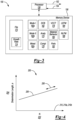
- the test system 140 generally includes a load frame 142 and a computer 150.
- the load frame 142 includes a camera 144 and multiple (e.g., two) end blocks 146a-146b.
- the test system 140 is operational to automatically exercise the structure 100 to cause an approximately constant strain energy release rate 118 due to the crack 102.
- the test system 140 may be characterized by an absence (or lack thereof) of a test operator 90 that controls the testing through manual adjustments of the adjustable stimulus and/or conducts manual measurements 92 of the crack size 104.
- a command signal 152 is generated by the computer 150 and presented to the load frame 142.
- the command signal 152 controls the adjustable stimulus 120 that the load frame 142 applies to the structure 100.
- the adjustable stimulus 120 may be an adjustable load 120a.
- the adjustable stimulus 120 may be an adjustable displacement 120b.
- the command signal 152 generally conveys information for the amplitude 122 of the adjustable stimulus 120.
- the camera 144 generates a measurement signal 154 received by the computer 150.
- the measurement signal 154 conveys the response 112 of the structure 100 to the adjustable stimulus 120.
- the load frame 142 implements an instrumented variable load frame.
- the load frame 142 is operational to apply repeatedly the adjustable stimulus 120 to the structure 100 over multiple cycles, and measure the response 112 of the structure 100 subjected to the adjustable stimulus 120 in each cycle.
- the adjustable stimulus 120 is controlled by the computer 150 through the command signal 152.
- the measured response 112 of the structure 100 to the adjustable stimulus 120 is presented in the measurement signal 154 from the load frame 142 to the computer 150.
- the camera 144 implements an optical camera.
- the camera 144 is operational to measure the response 112 of the structure 100 to the adjustable stimulus 120.
- the measured response 112 is transmitted to the computer 150 in the measurement signal 154.
- the end blocks 146a-146b implement temporary connections between the load frame 142 and the structure 100.
- the end blocks 146a-146b are secured to the structure 100 approximately at the first end 108 of the structure 100 on either side of the crack 102.
- the end blocks 146a-146b transfer the adjustable stimulus 120 from the load frame 142 to the structure 100 to expand the crack 102.
- the computer 150 implements one or more data processing computers.
- the computer 150 is connected to the load frame 142 and the camera 144. In embodiments with multiple computers 150, the individual computers 150 are coupled together to share data, memory space, and processing resources.
- the computer 150 may be operational to store configuration parameters used for testing the structure 100, execute software used to control the load frame 142, and execute software that analyzes the information received from the camera 144.
- the measurements received from the camera 144 are processed to determine the growth rate 114 of the crack 102. Data for the growth rate 114 is stored in a file.
- the growth rate 114 is generally suitable for analysis by one or more analytical techniques.
- the computer 150 may be configured by the software to perform one or more of a variety of tests on the structure 100.
- the tests may include, but are not limited to, a double cantilevered beam test and a fracture toughness testing in Mode I, Mode II (e.g., end notch flexure/edge notch flexure test), and various combinations of mixed Mode I/Mode II tests. Other tests may be implemented to meet the design criteria of a particular application.
- the computer 150 may be configured by the software to perform one or more of a variety of analysis techniques on the measurement data to determine fatigue properties of the structure 100.
- the analysis may include, but are not limited to, analytical techniques, compliance calculations, the virtual crack closure technique, material behavior analyses (e.g., closed form solution for crack growth), Paris Law behavior, linear elastic fracture mechanics technique, and nonlinear fracture mechanics technique.
- material behavior analyses e.g., closed form solution for crack growth
- Paris Law behavior e.g., Paris Law behavior
- linear elastic fracture mechanics technique e.g., linear elastic fracture mechanics technique
- nonlinear fracture mechanics technique e.g., nonlinear fracture mechanics technique.
- Other analysis techniques may be implemented to meet the design criteria of a particular application.
- the computer 150 may include one or more processors 156 (one shown) and one or more memory devices 158 (one shown).
- the processor 156 may generate the command signal 152 and receive the measurement signal 154.
- the processor 156 implements one or more processors within the computer 150.
- the processor 156 is in communication with the memory device 158 to exchange commands and data.
- the processor 156 is operational to execute the software tools used to control the load frame 142 via the command signal 152 and analyze the data measured received from the camera 144 in the measurement signal 154.
- the memory device 158 is in communication with the processor 156.
- the memory device 158 may implement a non-transitory storage medium and a transitory storage medium (e.g., random access memory, read-only memory, magnetic hard drives, solid-state drives, etc.).
- the non-transitory storage medium may hold one or more instructions (or software programs) executed by the processor 156 to perform the tests and analyze the measured data.
- the transitory storage medium may hold at least the file 170 that stores the calculated growth rate data 114 of the crack 102 ( FIG. 1 ).
- the software programs may include the Mode I test 160a, the Mode II test 160b, the mixture 160c of the Mode I test and the Mode II test, the double cantilevered beam test 162, the analytical technique 174, the compliance calculations 176, the virtual crack closure technique (VCCT) 178, and material behavior 180 based on a closed form solution for crack growth such as the Paris Law behavior 182, the linear elastic fracture mechanics (LEFM) technique 184, and the nonlinear fracture mechanics (NLFM) technique 186.
- Other software programs may be implemented to meet the design criteria of a particular application.
- other data analysis techniques may be energy-based techniques such as cohesive models, and crack band/traction-separation implementations of energy-based techniques.
- the double cantilever beam test is a test method for measuring Mode I fracture toughness of unidirectional composites.
- Mode II toughness a composite structure similar to is used and is loaded in a three-point bending configuration.
- the compliance reflects an ability to change a shape of the structure 100 when the adjustable stimulus 120 is applied.
- the compliance of a system is defined as the change in volume that occurs per unit change in the pressure of the system. In other words, the compliance is the ease with which an elastic structure stretches. In particular, the compliance is a measurement of the elastic resistance of the structure 100.
- the closed form solutions are based on the compliance calculations, and the unknown parameter being solved is the crack size 104.
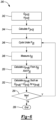
- the graph 200 includes an X-axis 202 and a Y-axis 204.
- the X-axis 202 indicates a number of cycles 210 (N) that the structure 100 is subjected to by the adjustable stimulus 120.
- the Y-axis 204 indicates a delamination length (a) (e.g., the crack length).
- a curve 206 represents the delamination length as a function of the number of cycles 210 for a constant strain energy release rate 118.
- a slope 208 of the curve 206 may be a constant.
- the slope 208 establishes a single point for da/dN, or Paris Law behavior, of the structure 100 at a particular strain energy release rate 118.
- Multiple da/dN points for multiple strain energy release rates 118 characterize an interlaminar fatigue property of a composite structure 100a. Due to the clean nature of the automated measurements, the da/dN behavior may be determined in less than the hundreds to thousands of cycles used in some existing techniques.
- the graph 220 includes an X-axis 222 and a Y-axis 224.
- the X-axis 222 indicates a rate of crack propagation (G max ) in units of kilojoules/meters 2 .
- the Y-axis 224 indicates the da/dN behavior of the structure 100 in units of millimeters/cycle.
- a curve 226 illustrates an example set of da/dN points (see FIG. 4 ) measured from a structure 100 at multiple strain energy release rates 118.
- the da/dN behavior is approximately inversely related to the number of cycles 210 (e.g., da/dN ⁇ 1/N).
- a first threshold 2208 the crack 102 ( FIG. 1 ) generally does not grow.
- a second threshold 230 the crack 102 propagates at an exponentially increasing rate.
- test method 240 for determining fatigue properties of a structure is shown in accordance with one or more exemplary embodiments.
- the test method (or process) 240 may be performed by the test system 140 on a structure 100.
- the test method 240 generally includes steps 242 to 256, as illustrated.
- the sequence of steps is shown as a representative example. Other step orders may be implemented to meet the criteria of a particular application.
- the method 240 starts by using the closed form solution to set a target stimulation.
- the adjustable stimulus 120 P [t-0]
- the adjustable stimulus 120 is calculated at the initial time.
- the adjustable stimulus 120 (P) is prescribed in the step 246.
- the response 112 e.g., displacement D [t]
- the closed form solution is used to calculate an updated crack size 104b (a [t+dt] ) from the displacement D [t] and the stimulus P [t] .
- a check is performed to determine if the next cycle 210b may be run. If more cycles 210 are appropriate, the method 240 returns to the step 246 for another cycle 210. If not, the testing ends in the step 256.
- the adjustable stimulus 120 is reduced (e.g., lowered) in accordance with the targeted strain energy release rate value G.
- the test data is subsequently used to determine the crack size 104 versus the cycle response, from which the slope of the curve is da/dN at the constant value G.
- Individual data points are extracted from each targeted strain energy release rate 118 and plotted to form the da/dN curve (e.g., curve 226 in FIG. 5 ).
- the slope of the curve 226 is the property entered into the virtual crack closure technique 178 as input data for the Paris Law behavior 182.
- the computer control replaces the test operator 90 ( FIG. 2 ) to measure the crack size 104.
- the approach also reduces scatter in the data points and so provides an improved fit for the Paris Law parameters using orders of magnitude fewer structures 100/test data points.
- the method (or process) 270 may be performed by the test system 140 on a structure 100.
- the test method 240 generally includes steps 272 to 300, as illustrated. The sequence of steps is shown as a representative example. Other step orders may be implemented to meet the criteria of a particular application.
- the structure 100 is mounted in the load frame 142.
- the computer 150 initializes the adjustable stimulus 120 exerted on the structure 100 by the load frame 142 based on the crack size 104 and the strain energy release rate 118 in the step 274 (same as step 242 in the method 240).
- the initial crack size 104a is stored in the memory device 158 in the step 276 at the start of the cycles 210.
- the adjustable stimulus 120 is applied to the structure 100 in an initial cycle 210 and is repeatedly applied over multiple cycles 210. During each cycle 210, the response 112 of the structure 100 is measured by the camera 144 in the step 280 and the measurement data presented to the computer 150.
- the computer 150 updates the crack size 104b used in a next cycle 210b based on the measured response 112 in the current cycle 210a and the adjustable stimulus 120 used in the current cycle 210a.
- the updating of the crack size 104b generally includes calculating a new value 104c of the crack size 104b with the analytical technique 174 based on the compliance calculation 176 in the step 284.
- the computer 150 updates the adjustable stimulus 120 to be used in the next cycle 210b.
- the adjustable stimulus 120 maintains the strain energy release rate 118 approximately constant based on updated the crack size 104b expected in the next cycle 210b.
- the updating of the adjustable stimulus 120 may be a lowering of the amplitude 122 of the adjustable stimulus 120 in the step 288 as the crack size 104 of the crack 102 increases.
- the adjustable stimulus 120 may be manually adjusted from time to time as the crack size 104 increases.
- the computer 150 calculates the growth rate 114 of the crack propagation 116 in the structure 100 based on the response 112 in each cycle 210.
- the different values of the adjustable stimulus 120 are applied in the subsequent cycles 210 to maintain the strain energy release rate 118 approximately constant.
- the computer 150 stores the growth rate 114 in the file 170.
- the application of the adjustable stimulus 120 to the structure 100, the measurement of the response 112, the update of the crack size 104b, the update of the adjustable stimulus 120, and the calculation of the growth rate 114 are repeated at multiple different strain energy release rates in the step 296.
- the slope of the da/dN curve is calculated in the step 298 as a function of the cycles 210.
- the Paris Law behavior of the crack 102 within the structure 100 is determined based on the growth rate 114 at the various different strain energy release rates 118. Other analysis techniques and subsequent behavior determinations may be implemented to meet the design criteria of a particular application.
- the aircraft 320 may include one or more structures 100 and/or one or more composite structure 100a.
- the aircraft 320 includes an airframe 322 with a plurality of systems 324 and an interior 326.
- Examples of the systems 324 include one or more of a propulsion system 328, an electrical system 330, a hydraulic system 332, and an environmental system 334.
- Various numbers of other systems may be included.
- an aerospace example is shown, the principles of the disclosure may be applied to other industries, such as the automotive industry.
- the test system 140 and associated methods includes a feedback loop that automatically calculates the location of the crack tip resulting in a constant strain energy release rate loading.
- the solution provides a constant G stimulus (e.g., loading or displacements). The solution ensures that as the crack advances, there is no change in the strain energy release rate. the constant strain energy release rate results in improved measurements of the da/dN behavior for a given approach.
- a test operator is not relied upon to measure the crack growth for each cycle. Due to the clean nature of the measurements, the testing may be reduced below millions of cycles to generate the da/dN response. The reduced number of cycles saves time, budget, and enables quicker decision making for analysis work.
- a single specimen may be used to generate multiple data points on the da/dN curves so fewer numbers of specimens are consumed to develop the constant G curves. Furthermore, the solution reduces the scatter associated with the da/dN curves enabling engineers to have confidence in the properties being measured.
- the solution may be applicable to other test methods for interlaminar testing, namely Mode II response, and mixed-Mode I/Mode II responses.
- the test system 140 and associated methods may be used to determine both interlaminar (e.g., ply) and intralaminar (e.g., laminate) constant G values using similar approaches. The underlying theory may be modified for the different cases, but the fracture mechanics and test approach may be similar.
Landscapes
- Physics & Mathematics (AREA)
- General Physics & Mathematics (AREA)
- General Health & Medical Sciences (AREA)
- Chemical & Material Sciences (AREA)
- Analytical Chemistry (AREA)
- Biochemistry (AREA)
- Life Sciences & Earth Sciences (AREA)
- Health & Medical Sciences (AREA)
- Immunology (AREA)
- Pathology (AREA)
- Engineering & Computer Science (AREA)
- Aviation & Aerospace Engineering (AREA)
- Investigating Strength Of Materials By Application Of Mechanical Stress (AREA)
- Testing Of Devices, Machine Parts, Or Other Structures Thereof (AREA)
Abstract
Description
- The disclosure relates generally to structural testing, and in particular, to determining structure fatigue properties.
- Design approaches in composite structures generally account for fatigue damage in interlaminar domains (i.e., damage between plies, adhesive interfaces, co-bonded interfaces, co-cured interfaces, and combinations thereof). Verifying that the fatigue damage in an aircraft does not initiate and grow under cyclical loading involves lengthy testing. Historically, the airworthiness compliance and certification is achieved through physical testing with representative damage demonstrating that the damage does not grow under spectrum loads. Such physical testing is usually time consuming and expensive. As a result, identifying potential failure modes during design-test-certification building blocks is difficult.
- Accordingly, those skilled in the art continue with research and development efforts in the field of simplifying structural fatigue property testing.
- A method for determining fatigue properties of a structure is provided herein. The method includes mounting the structure in a load frame. The structure has a crack with a crack size. The method includes applying repeatedly an adjustable stimulus to the structure over a plurality of cycles. The adjustable stimulus is an adjustable load or an adjustable displacement applied to the structure. The method further includes storing the crack size at a start of the plurality of cycles, measuring a response of the structure subjected to the adjustable stimulus in each of the plurality of cycles, updating the crack size based on the response in each of the plurality of cycles, and updating the adjustable stimulus in each of the plurality of cycles. The adjustable stimulus as updated maintains a strain energy release rate approximately constant based on the crack size. The method includes calculating a growth rate of a crack propagation in the structure based on the response in each of the plurality of cycles, and storing the growth rate in a file.
- In one or more embodiments, the method includes repeating the applying of the adjustable stimulus, the measuring of the response, the updating of the crack size, the updating of the adjustable stimulus, and the calculating of the growth rate at a plurality of different strain energy release rates.
- In one or more embodiments, the method includes calculating a Paris Law behavior of the crack within the structure based on the growth rate at the plurality of different strain energy release rates.
- In one or more embodiments of the method, the load frame is operational to perform a Mode I test, a Mode II test, or a mixture of the Mode I test and the Mode II test.
- In one or more embodiments of the method, the updating of the adjustable stimulus includes lowering an amplitude of the adjustable stimulus as the crack size of the crack increases.
- In one or more embodiments of the method, the calculating of the growth rate of the crack propagation includes calculating a slope of a curve of the crack size as a function the plurality of cycles.
- In one or more embodiments of the method, the updating of the crack size in the structure includes calculating a new value of the crack size with an analytical technique based on a compliance calculation.
- In one or more embodiments of the method, the analytical technique is a linear elastic fracture mechanics technique or a nonlinear fracture mechanics technique.
- In one or more embodiments of the method, the crack size determined during the plurality of cycles is characterized by a lack of a manual measurement of the crack size by a test operator.
- A test system is provided herein. The test system includes a load frame and a computer. The load frame is operational to apply repeatedly an adjustable stimulus to a structure over a plurality of cycles. The structure has a crack with a crack size, and the adjustable stimulus is an adjustable load or an adjustable displacement applied to the structure. The load frame is further operational to measure a response of the structure subjected to the adjustable stimulus in each of the plurality of cycles. The computer is coupled to the load frame and is operational to store the crack size at a start of the plurality of cycles, update the crack size based on the response in each of the plurality of cycles, and update the adjustable stimulus in each of the plurality of cycles. The adjustable stimulus as updated maintains a strain energy release rate approximately constant based on the crack size. The computer is further operational to calculate a growth rate of a crack propagation in the structure based on the response in each of the plurality of cycles, and store the growth rate in a file.
- In one or more embodiments of the test system, the load frame and the computer are further operational to repeat the application of the adjustable stimulus, the measurement of the response, the update of the crack size, the update of the adjustable stimulus, and the calculation of the growth rate at a plurality of different strain energy release rates.
- In one or more embodiments of the test system, the computer is further operational to calculate a Paris Law behavior of the crack within the structure based on the growth rate at the plurality of different strain energy release rates.
- In one or more embodiments of the test system, the load frame is operational to perform a Mode I test, a Mode II test, or a mixture of the Mode I test and the Mode II test.
- In one or more embodiments of the test system, the update of the adjustable stimulus includes to lower an amplitude of the adjustable stimulus as the crack size of the crack increases.
- In one or more embodiments to the test system, the calculation of the growth rate of the crack propagation includes to calculate a slope of a curve of the crack size as a function the plurality of cycles.
- In one or more embodiments of the test system, the update of the crack size in the structure includes to calculate a new value of the crack size with an analytical technique based on a compliance calculation.
- In one or more embodiments of the test system, the analytical technique is a linear elastic fracture mechanics technique or a nonlinear fracture mechanics technique.
- In one or more embodiments of the test system, the crack size determined during the plurality of cycles is characterized by a lack of a manual measurement of the crack size by a test operator.
- In one or more embodiments of the test system, the structure is a composite structure that forms a part of an aircraft.
- A method for determining fatigue properties of a structure is provided herein. The method includes mounting the composite structure in a load frame. The composite structure has a crack with a crack size. The method includes initializing an adjustable stimulus exerted on the composite structure by the load frame based on the crack size and a strain energy release rate, and applying the adjustable stimulus to the composite structure in a current cycle of a plurality of cycles. The adjustable stimulus is an adjustable load or an adjustable displacement applied to the composite structure. The method further includes measuring a response of the composite structure in the current cycle, updating the crack size used in a next cycle of the plurality of cycles based on the response as measured in the current cycle and the adjustable stimulus used in the current cycle, and updating the adjustable stimulus used in the next cycle. The adjustable stimulus in the next cycle maintains the strain energy release rate approximately constant based on the crack size used in the next cycle. The method includes applying a plurality of different values of the adjustable stimulus over the plurality of cycles, calculating a growth rate of a crack propagation in the composite structure based on the response in each of the plurality of cycles, and storing the growth rate in a file.
- The above features and advantages, and other features and advantages of the present disclosure are readily apparent from the following detailed description of the best modes for carrying out the disclosure when taken in connection with the accompanying drawings.
-
-
FIG. 1 is a schematic diagram of a structure under test in accordance with one or more exemplary embodiments. -
FIG. 2 is a schematic diagram of a test system in accordance with one or more exemplary embodiments. -
FIG. 3 is a schematic diagram of a computer in the test system in accordance with one or more exemplary embodiments. -
FIG. 4 is a graph of a delamination length as a function of cycles in accordance with one or more exemplary embodiments. -
FIG. 5 is a graph of Paris law behavior in accordance with one or more exemplary embodiments. -
FIG. 6 is a flow diagram of a test method for determining fatigue properties of the structure in accordance with one or more exemplary embodiments. -
FIG. 7 is a flow diagram of a detailed method for determining the fatigue properties of the structure in accordance with one or more exemplary embodiments. -
FIG. 8 is a schematic diagram of components of an aircraft in accordance with one or more exemplary embodiments. - Embodiments of the present disclosure include a method and/or a test system for automatically determining fatigue properties of structures (e.g., composite structures). A feedback loop is used to automatically calculate a location of a crack tip of a crack in a structure under test resulting in a constant strain energy release rate loading/displacement. An automation load/displacement shedding process maintains the constant strain energy release rate loading/displacement as the crack grows.
- A structural analysis may use a virtual crack closure technique (VCCT) to simulate an interlaminar fatigue response from the composite structure coupons through large structural length scales (configured structure). The virtual crack closure technique is a numerical implementation of linear elastic fracture mechanics (LEFM) technique. The linear elastic fracture mechanics is modeled using a slow growth mathematical model where the delamination/disbond grows a finite distance "a" for each cycle N. The result is known as Paris Law crack propagation and is represented graphically as a slope da/dN. The equation governing da/dN growth is given as a function of strain energy release rate G, but is fixed for a given R-ratio (relationship between a maximum applied load/displacement and a minimum applied load/displacement). A similar approach is used for energy-based cohesive methods. Other types of fatigue/cyclic loadings may include, but are not limited to, constant amplitude, block amplitude, and random block amplitude (from less complex up to full spectrum complexity).
- The slope of the Paris Law involves testing of numerous coupons to generate the properties as inputs to the virtual crack closure technique analysis. For composite structures, the properties are modal based depending on the type of loading. The analysis may utilize Mode I (opening mode) and/or Mode II (sliding mode) crack growth rates. A test used to determine the property for the Mode I is a double cantilevered beam (DCB) test. The Paris Law behavior (e.g., da/dN) is determined over a range of strain energy release rates G from an onset of crack growth (e.g., a first threshold) to rapid crack propagation (e.g., a second threshold).
- The double cantilevered beam test output data (e.g., load-displacement) is represented by the linear elastic fracture mechanics mathematical model. Through the linear elastic fracture mechanics, the experimental response may be idealized to relate the force, displacement, and location of the crack. The closed form solution comes in many forms. An example closed form solution is provided by equation 1 as follows:

- Where w is a specimen width, E is an E11 modulus, t is a specimen thickness, and h is a half specimen thickness. The parameters w, E,t, and h are known properties. The parameters α1, α2, and α3 are constants. By way of example, the constants may be 3.8, 3.78, and 1.0, respectively. Other values may be used based on the type of system being tested.
- By running a static test, the constants may be anchored accordingly to describe a material-specific response. Since force and displacement are related by compliance, and the compliance is a function of crack length, the crack length is determinable from the load frame during testing using the closed form solution. Therefore, the load/displacement is automatically adjusted as the crack grows to maintain a constant strain energy release rate G throughout a test. The closed form solution, once calibrated, provides an accurate description of the relationship between the applied load, the displacement, the targeted strain energy release rate G value, and the location of the crack.
- Referring to
FIG. 1 , a schematic diagram of anexample structure 100 under test is shown in accordance with one or more exemplary embodiments. In various embodiments, the structure 100 (or coupon) may be a composite structure 100a formed from composite materials. In other embodiments, thestructure 100 may be formed from one or more metals. Thestructure 100 has a general bar shape with afirst end 108 and asecond end 110. Thecrack 102 is formed in thestructure 100 at thefirst end 108. - The
crack 102 may have a crack size 104 (or crack length). Acrack tip 106 is defined as an end of thecrack 102 opposite thefirst end 108 of thestructure 100. Before testing begins, the crack size 104 may be referred to as an initial crack size 104a (or initial crack length). As the testing proceeds, the crack size 104 grows to an updated crack size 104b having a new value 104c for the crack length. - With the
second end 110 of thestructure 100 secured to a load frame, an adjustable stimulus (e.g., an adjustable load or an adjustable displacement) applied at thefirst end 108 of thestructure 100 causes aresponse 112 of thestructure 100. Theresponse 112 is generally a bending of the structure 100 (e.g., bending up and down as illustrated). The adjustable stimulus 120 generally has an amplitude 122. The bending causes a crack propagation 116 of the crack 102 (e.g., right to left as illustrated) at agrowth rate 114 for a constant strainenergy release rate 118. - Referring to
FIG. 2 , a schematic diagram of an example implementation of atest system 140 is shown in accordance with one or more exemplary embodiments. Thetest system 140 generally includes aload frame 142 and acomputer 150. Theload frame 142 includes acamera 144 and multiple (e.g., two)end blocks 146a-146b. Thetest system 140 is operational to automatically exercise thestructure 100 to cause an approximately constant strainenergy release rate 118 due to thecrack 102. Thetest system 140 may be characterized by an absence (or lack thereof) of atest operator 90 that controls the testing through manual adjustments of the adjustable stimulus and/or conducts manual measurements 92 of the crack size 104. - A
command signal 152 is generated by thecomputer 150 and presented to theload frame 142. Thecommand signal 152 controls the adjustable stimulus 120 that theload frame 142 applies to thestructure 100. In various embodiments, the adjustable stimulus 120 may be anadjustable load 120a. In other embodiments, the adjustable stimulus 120 may be anadjustable displacement 120b. Thecommand signal 152 generally conveys information for the amplitude 122 of the adjustable stimulus 120. Thecamera 144 generates ameasurement signal 154 received by thecomputer 150. Themeasurement signal 154 conveys theresponse 112 of thestructure 100 to the adjustable stimulus 120. - The
load frame 142 implements an instrumented variable load frame. Theload frame 142 is operational to apply repeatedly the adjustable stimulus 120 to thestructure 100 over multiple cycles, and measure theresponse 112 of thestructure 100 subjected to the adjustable stimulus 120 in each cycle. The adjustable stimulus 120 is controlled by thecomputer 150 through thecommand signal 152. The measuredresponse 112 of thestructure 100 to the adjustable stimulus 120 is presented in themeasurement signal 154 from theload frame 142 to thecomputer 150. - The
camera 144 implements an optical camera. Thecamera 144 is operational to measure theresponse 112 of thestructure 100 to the adjustable stimulus 120. The measuredresponse 112 is transmitted to thecomputer 150 in themeasurement signal 154. - The end blocks 146a-146b implement temporary connections between the
load frame 142 and thestructure 100. The end blocks 146a-146b are secured to thestructure 100 approximately at thefirst end 108 of thestructure 100 on either side of thecrack 102. The end blocks 146a-146b transfer the adjustable stimulus 120 from theload frame 142 to thestructure 100 to expand thecrack 102. - The
computer 150 implements one or more data processing computers. Thecomputer 150 is connected to theload frame 142 and thecamera 144. In embodiments withmultiple computers 150, theindividual computers 150 are coupled together to share data, memory space, and processing resources. Thecomputer 150 may be operational to store configuration parameters used for testing thestructure 100, execute software used to control theload frame 142, and execute software that analyzes the information received from thecamera 144. The measurements received from thecamera 144 are processed to determine thegrowth rate 114 of thecrack 102. Data for thegrowth rate 114 is stored in a file. Thegrowth rate 114 is generally suitable for analysis by one or more analytical techniques. - In various embodiments, the
computer 150 may be configured by the software to perform one or more of a variety of tests on thestructure 100. The tests may include, but are not limited to, a double cantilevered beam test and a fracture toughness testing in Mode I, Mode II (e.g., end notch flexure/edge notch flexure test), and various combinations of mixed Mode I/Mode II tests. Other tests may be implemented to meet the design criteria of a particular application. In some embodiments, thecomputer 150 may be configured by the software to perform one or more of a variety of analysis techniques on the measurement data to determine fatigue properties of thestructure 100. The analysis may include, but are not limited to, analytical techniques, compliance calculations, the virtual crack closure technique, material behavior analyses (e.g., closed form solution for crack growth), Paris Law behavior, linear elastic fracture mechanics technique, and nonlinear fracture mechanics technique. Other analysis techniques may be implemented to meet the design criteria of a particular application. - Referring to
FIG. 3 , a schematic diagram of an example implementation of thecomputer 150 is shown in accordance with one or more exemplary embodiments. Thecomputer 150 may include one or more processors 156 (one shown) and one or more memory devices 158 (one shown). Theprocessor 156 may generate thecommand signal 152 and receive themeasurement signal 154. - The
processor 156 implements one or more processors within thecomputer 150. Theprocessor 156 is in communication with thememory device 158 to exchange commands and data. Theprocessor 156 is operational to execute the software tools used to control theload frame 142 via thecommand signal 152 and analyze the data measured received from thecamera 144 in themeasurement signal 154. - The
memory device 158 is in communication with theprocessor 156. Thememory device 158 may implement a non-transitory storage medium and a transitory storage medium (e.g., random access memory, read-only memory, magnetic hard drives, solid-state drives, etc.). The non-transitory storage medium may hold one or more instructions (or software programs) executed by theprocessor 156 to perform the tests and analyze the measured data. The transitory storage medium may hold at least thefile 170 that stores the calculatedgrowth rate data 114 of the crack 102 (FIG. 1 ). The software programs may include the Mode I test 160a, theMode II test 160b, themixture 160c of the Mode I test and the Mode II test, the doublecantilevered beam test 162, theanalytical technique 174, thecompliance calculations 176, the virtual crack closure technique (VCCT) 178, andmaterial behavior 180 based on a closed form solution for crack growth such as theParis Law behavior 182, the linear elastic fracture mechanics (LEFM)technique 184, and the nonlinear fracture mechanics (NLFM)technique 186. Other software programs may be implemented to meet the design criteria of a particular application. For example, other data analysis techniques may be energy-based techniques such as cohesive models, and crack band/traction-separation implementations of energy-based techniques. - The double cantilever beam test is a test method for measuring Mode I fracture toughness of unidirectional composites. For Mode II toughness, a composite structure similar to is used and is loaded in a three-point bending configuration.
- The compliance reflects an ability to change a shape of the
structure 100 when the adjustable stimulus 120 is applied. The compliance of a system is defined as the change in volume that occurs per unit change in the pressure of the system. In other words, the compliance is the ease with which an elastic structure stretches. In particular, the compliance is a measurement of the elastic resistance of thestructure 100. The closed form solutions are based on the compliance calculations, and the unknown parameter being solved is the crack size 104. - Referring to
FIG. 4 , agraph 200 of an example delamination length as a function of cycles is shown in accordance with one or more exemplary embodiments. Thegraph 200 includes anX-axis 202 and a Y-axis 204. TheX-axis 202 indicates a number of cycles 210 (N) that thestructure 100 is subjected to by the adjustable stimulus 120. The Y-axis 204 indicates a delamination length (a) (e.g., the crack length). - A
curve 206 represents the delamination length as a function of the number of cycles 210 for a constant strainenergy release rate 118. Ideally, aslope 208 of thecurve 206 may be a constant. Theslope 208 establishes a single point for da/dN, or Paris Law behavior, of thestructure 100 at a particular strainenergy release rate 118. Multiple da/dN points for multiple strainenergy release rates 118 characterize an interlaminar fatigue property of a composite structure 100a. Due to the clean nature of the automated measurements, the da/dN behavior may be determined in less than the hundreds to thousands of cycles used in some existing techniques. - Referring to
FIG. 5 , agraph 220 of an example implementation of Paris law behavior is shown in accordance with one or more exemplary embodiments. Thegraph 220 includes anX-axis 222 and a Y-axis 224. TheX-axis 222 indicates a rate of crack propagation (Gmax) in units of kilojoules/meters2. The Y-axis 224 indicates the da/dN behavior of thestructure 100 in units of millimeters/cycle. - A
curve 226 illustrates an example set of da/dN points (seeFIG. 4 ) measured from astructure 100 at multiple strain energy release rates 118. The da/dN behavior is approximately inversely related to the number of cycles 210 (e.g., da/dN ~ 1/N). Below afirst threshold 228, the crack 102 (FIG. 1 ) generally does not grow. Above asecond threshold 230, thecrack 102 propagates at an exponentially increasing rate. Between thefirst threshold 228 and thesecond threshold 230, thecrack 102 generally propagates at a constant rate. The constant rate may be expressed by equation 2 as follows:

- Where C and m are characteristics of the structure material.
- Referring to
FIG. 6 , a flow diagram of anexample test method 240 for determining fatigue properties of a structure is shown in accordance with one or more exemplary embodiments. The test method (or process) 240 may be performed by thetest system 140 on astructure 100. Thetest method 240 generally includessteps 242 to 256, as illustrated. The sequence of steps is shown as a representative example. Other step orders may be implemented to meet the criteria of a particular application. - Referring to
FIG. 6 andFIG. 1 , themethod 240 starts by using the closed form solution to set a target stimulation. The stimulation is used in thestep 242 to calculate the constant value G[t-0] for the strainenergy release rate 118 and an initial crack size 104a (a[t=0]) at an initial time for the cycling target of interest. In thestep 244, the adjustable stimulus 120 (P[t-0]) is calculated at the initial time. For each cycle 210 (dt), the adjustable stimulus 120 (P) is prescribed in thestep 246. The response 112 (e.g., displacement D[t]) is measured in thestep 248 from theload frame 142 in a current cycle 210a. In thestep 250, the closed form solution is used to calculate an updated crack size 104b (a[t+dt]) from the displacement D[t] and the stimulus P[t]. In thestep 252, the updated stimulus P[t+dt] in a next cycle 210b is solved for in the closed form solution to ensure that the G value is constant (e.g., G[t+dt] = G[t-0] at the crack length a[t+dt]) during the testing. Therefore, the testing may be automated instead of manual. In thestep 254, a check is performed to determine if the next cycle 210b may be run. If more cycles 210 are appropriate, themethod 240 returns to thestep 246 for another cycle 210. If not, the testing ends in thestep 256. - As the
crack 102 grows, the adjustable stimulus 120 is reduced (e.g., lowered) in accordance with the targeted strain energy release rate value G. In various embodiments, the test data is subsequently used to determine the crack size 104 versus the cycle response, from which the slope of the curve is da/dN at the constant value G. Individual data points are extracted from each targeted strainenergy release rate 118 and plotted to form the da/dN curve (e.g.,curve 226 inFIG. 5 ). The slope of thecurve 226 is the property entered into the virtualcrack closure technique 178 as input data for theParis Law behavior 182. The computer control replaces the test operator 90 (FIG. 2 ) to measure the crack size 104. The approach also reduces scatter in the data points and so provides an improved fit for the Paris Law parameters using orders of magnitudefewer structures 100/test data points. - Referring to
FIG. 7 , a flow diagram of an exampledetailed method 270 for determining fatigue properties of a structure is shown in accordance with one or more exemplary embodiments. The method (or process) 270 may be performed by thetest system 140 on astructure 100. Thetest method 240 generally includessteps 272 to 300, as illustrated. The sequence of steps is shown as a representative example. Other step orders may be implemented to meet the criteria of a particular application. - Referring to
FIG. 1 ,FIG. 3 , andFIG. 7 , in thestep 272 thestructure 100 is mounted in theload frame 142. Thecomputer 150 initializes the adjustable stimulus 120 exerted on thestructure 100 by theload frame 142 based on the crack size 104 and the strainenergy release rate 118 in the step 274 (same asstep 242 in the method 240). The initial crack size 104a is stored in thememory device 158 in thestep 276 at the start of the cycles 210. - In the
step 278, the adjustable stimulus 120 is applied to thestructure 100 in an initial cycle 210 and is repeatedly applied over multiple cycles 210. During each cycle 210, theresponse 112 of thestructure 100 is measured by thecamera 144 in thestep 280 and the measurement data presented to thecomputer 150. - In the
step 282, thecomputer 150 updates the crack size 104b used in a next cycle 210b based on the measuredresponse 112 in the current cycle 210a and the adjustable stimulus 120 used in the current cycle 210a. The updating of the crack size 104b generally includes calculating a new value 104c of the crack size 104b with theanalytical technique 174 based on thecompliance calculation 176 in thestep 284. - In the
step 286, thecomputer 150 updates the adjustable stimulus 120 to be used in the next cycle 210b. The adjustable stimulus 120, as updated, maintains the strainenergy release rate 118 approximately constant based on updated the crack size 104b expected in the next cycle 210b. The updating of the adjustable stimulus 120 may be a lowering of the amplitude 122 of the adjustable stimulus 120 in thestep 288 as the crack size 104 of thecrack 102 increases. In various embodiments, the adjustable stimulus 120 may be manually adjusted from time to time as the crack size 104 increases. Thecomputer 150 calculates thegrowth rate 114 of the crack propagation 116 in thestructure 100 based on theresponse 112 in each cycle 210. In thestep 292, the different values of the adjustable stimulus 120 are applied in the subsequent cycles 210 to maintain the strainenergy release rate 118 approximately constant. - In the
step 294, thecomputer 150 stores thegrowth rate 114 in thefile 170. The application of the adjustable stimulus 120 to thestructure 100, the measurement of theresponse 112, the update of the crack size 104b, the update of the adjustable stimulus 120, and the calculation of thegrowth rate 114 are repeated at multiple different strain energy release rates in thestep 296. - For a Paris Law analysis, the slope of the da/dN curve is calculated in the
step 298 as a function of the cycles 210. In thestep 300, the Paris Law behavior of thecrack 102 within thestructure 100 is determined based on thegrowth rate 114 at the various different strain energy release rates 118. Other analysis techniques and subsequent behavior determinations may be implemented to meet the design criteria of a particular application. - Referring to
FIG. 8 , a schematic diagram of example components of anaircraft 320 is shown in accordance with one or more exemplary embodiments. Theaircraft 320 may include one ormore structures 100 and/or one or more composite structure 100a. Theaircraft 320 includes anairframe 322 with a plurality ofsystems 324 and an interior 326. Examples of thesystems 324 include one or more of apropulsion system 328, anelectrical system 330, ahydraulic system 332, and anenvironmental system 334. Various numbers of other systems may be included. Although an aerospace example is shown, the principles of the disclosure may be applied to other industries, such as the automotive industry. - The
test system 140 and associated methods includes a feedback loop that automatically calculates the location of the crack tip resulting in a constant strain energy release rate loading. The solution provides a constant G stimulus (e.g., loading or displacements). The solution ensures that as the crack advances, there is no change in the strain energy release rate. the constant strain energy release rate results in improved measurements of the da/dN behavior for a given approach. A test operator is not relied upon to measure the crack growth for each cycle. Due to the clean nature of the measurements, the testing may be reduced below millions of cycles to generate the da/dN response. The reduced number of cycles saves time, budget, and enables quicker decision making for analysis work. A single specimen may be used to generate multiple data points on the da/dN curves so fewer numbers of specimens are consumed to develop the constant G curves. Furthermore, the solution reduces the scatter associated with the da/dN curves enabling engineers to have confidence in the properties being measured. The solution may be applicable to other test methods for interlaminar testing, namely Mode II response, and mixed-Mode I/Mode II responses. In various embodiments, thetest system 140 and associated methods may be used to determine both interlaminar (e.g., ply) and intralaminar (e.g., laminate) constant G values using similar approaches. The underlying theory may be modified for the different cases, but the fracture mechanics and test approach may be similar. - This disclosure is susceptible of embodiments in many different forms. Representative embodiments of the disclosure are shown in the drawings and are herein described in detail with the understanding that these embodiments are provided as an exemplification of the disclosed principles, not limitations of the broad aspects of the disclosure. To that extent, elements and limitations that are described, for example, in the Abstract, Background, Summary, and Detailed Description sections, but not explicitly set forth in the claims, should not be incorporated into the claims, singly or collectively, by implication, inference, or otherwise.
- For purposes of the present detailed description, unless specifically disclaimed, the singular includes the plural and vice versa. The words "and" and "or" shall be both conjunctive and disjunctive. The words "any" and "all" shall both mean "any and all", and the words "including," "containing," "comprising," "having," and the like shall each mean "including without limitation." Moreover, words of approximation such as "about," "almost," "substantially," "approximately," and "generally," may be used herein in the sense of "at, near, or nearly at," or "within 0-5% of," or "within acceptable manufacturing tolerances," or other logical combinations thereof. Referring to the drawings, wherein like reference numbers refer to like components.
- The detailed description and the drawings or FIGS. are supportive and descriptive of the disclosure, but the scope of the disclosure is defined solely by the claims.
- Furthermore, the present disclosure comprises aspects according to the following clauses.
- Clause 1. A method for determining fatigue properties of a structure, the method comprising:
- mounting the structure in a load frame, wherein the structure has a crack with a crack size;
- applying repeatedly an adjustable stimulus to the structure over a plurality of cycles, wherein the adjustable stimulus is an adjustable load or an adjustable displacement applied to the structure;
- storing the crack size at a start of the plurality of cycles;
- measuring a response of the structure subjected to the adjustable stimulus in each of the plurality of cycles;
- updating the crack size based on the response in each of the plurality of cycles;
- updating the adjustable stimulus in each of the plurality of cycles, wherein the adjustable stimulus as updated maintains a strain energy release rate approximately constant based on the crack size;
- calculating a growth rate of a crack propagation in the structure based on the response in each of the plurality of cycles; and
- storing the growth rate in a file.
- Clause 2. The method according to clause 1, further comprising:
repeating the applying of the adjustable stimulus, the measuring of the response, the updating of the crack size, the updating of the adjustable stimulus, and the calculating of the growth rate at a plurality of different strain energy release rates. - Clause 3. The method according to clause 2, further comprising:
calculating a Paris Law behavior of the crack within the structure based on the growth rate at the plurality of different strain energy release rates. - Clause 4. The method according to clause 1, wherein the load frame is operational to perform a Mode I test, a Mode II test, or a mixture of the Mode I test and the Mode II test.
- Clause 5. The method according to clause 1, wherein the updating of the adjustable stimulus comprises:
lowering an amplitude of the adjustable stimulus as the crack size of the crack increases. - Clause 6. The method according to clause 5, wherein the calculating of the growth rate of the crack propagation comprises:
calculating a slope of a curve of the crack size as a function the plurality of cycles. - Clause 7. The method according to clause 1, wherein the updating of the crack size in the structure comprises:
calculating a new value of the crack size with an analytical technique based on a compliance calculation. - Clause 8. The method according to clause 7, wherein the analytical technique is a linear elastic fracture mechanics technique or a nonlinear fracture mechanics technique.
- Clause 9. The method according to clause 7, wherein the crack size determined during the plurality of cycles is characterized by a lack of a manual measurement of the crack size by a test operator.
- Clause 10. A test system comprising:
- a load frame operational to:
- apply repeatedly an adjustable stimulus to a structure over a plurality of cycles, wherein the structure has a crack with a crack size, and the adjustable stimulus is an adjustable load or an adjustable displacement applied to the structure; and
- measure a response of the structure subjected to the adjustable stimulus in each of the plurality of cycles; and
- a computer coupled to the load frame and operational to:
store the crack size at a start of the plurality of cycles; - update the crack size based on the response in each of the plurality of cycles;
- update the adjustable stimulus in each of the plurality of cycles, wherein the adjustable stimulus as updated maintains a strain energy release rate approximately constant based on the crack size;
- calculate a growth rate of a crack propagation in the structure based on the response in each of the plurality of cycles; and
- store the growth rate in a file.
- a load frame operational to:
- Clause 11. The test system according to clause 10, wherein the load frame and the computer are further operational to:
repeat the application of the adjustable stimulus, the measurement of the response, the update of the crack size, the update of the adjustable stimulus, and the calculation of the growth rate at a plurality of different strain energy release rates. - Clause 12. The test system according to clause 11, wherein the computer is further operational to:
calculate a Paris Law behavior of the crack within the structure based on the growth rate at the plurality of different strain energy release rates. - Clause 13. The test system according to clause 10, wherein the load frame is operational to perform a Mode I test, a Mode II test, or a mixture of the Mode I test and the Mode II test.
- Clause 14. The test system according to clause 10, wherein the update of the adjustable stimulus comprises:
lower an amplitude of the adjustable stimulus as the crack size of the crack increases. - Clause 15. The test system according to clause 14, wherein the calculation of the growth rate of the crack propagation comprises:
calculate a slope of a curve of the crack size as a function the plurality of cycles. - Clause 16. The test system according to clause 10, wherein the update of the crack size in the structure comprises:
calculate a new value of the crack size with an analytical technique based on a compliance calculation. - Clause 17. The test system according to clause 16, wherein the analytical technique is a linear elastic fracture mechanics technique or a nonlinear fracture mechanics technique.
- Clause 18. The test system according to clause 16, wherein the crack size determined during the plurality of cycles is characterized by a lack of a manual measurement of the crack size by a test operator.
- Clause 19. The test system according to clause 10, wherein the structure is a composite structure that forms a part of an aircraft.
- 20. A method for determining fatigue properties in a composite structure, the method comprising:
- mounting the composite structure in a load frame, wherein the composite structure has a crack with a crack size;
- initializing an adjustable stimulus exerted on the composite structure by the load frame based on the crack size and a strain energy release rate;
- applying the adjustable stimulus to the composite structure in a current cycle of a plurality of cycles, wherein the adjustable stimulus is an adjustable load or an adjustable displacement applied to the composite structure;
- measuring a response of the composite structure in the current cycle;
- updating the crack size used in a next cycle of the plurality of cycles based on the response as measured in the current cycle and the adjustable stimulus used in the current cycle;
- updating the adjustable stimulus used in the next cycle, wherein the adjustable stimulus in the next cycle maintains the strain energy release rate approximately constant based on the crack size used in the next cycle;
- applying a plurality of different values of the adjustable stimulus over the plurality of cycles;
- calculating a growth rate of a crack propagation in the composite structure based on the response in each of the plurality of cycles; and
- storing the growth rate in a file.
Claims (15)
- A method (270) for determining fatigue properties of a structure (100), the method comprising:mounting (272) the structure (100) in a load frame (142), wherein the structure (100) has a crack (102) with a crack size (104);applying (278) repeatedly an adjustable stimulus (120) to the structure (100) over a plurality of cycles (210), wherein the adjustable stimulus (120) is an adjustable load (120a) or an adjustable displacement (120b) applied to the structure (100);storing (276) the crack size (104) at a start of the plurality of cycles (210);measuring (280) a response (112) of the structure (100) subjected to the adjustable stimulus (120) in each of the plurality of cycles (210);updating (282) the crack size (104) based on the response (112) in each of the plurality of cycles (210);updating (286) the adjustable stimulus (120) in each of the plurality of cycles (210), wherein the adjustable stimulus (120) as updated maintains a strain energy release rate (118) approximately constant based on the crack size (104);calculating (290) a growth rate (114) of a crack propagation (116) in the structure (100) based on the response (112) in each of the plurality of cycles (210); andstoring (294) the growth rate (114) in a file (170).
- The method (270) according to claim 1, further comprising:
repeating (296) the applying (278) of the adjustable stimulus (120), the measuring (280) of the response (112), the updating (282) of the crack size (104), the updating (286) of the adjustable stimulus (120), and the calculating (290) of the growth rate (114) at a plurality of different strain energy release rates (118). - The method (270) according to claim 2, further comprising:
calculating (300) a Paris Law behavior (182) of the crack (102) within the structure (100) based on the growth rate (114) at the plurality of different strain energy release rates (118). - The method (270) according to any one of the preceding claims, wherein the load frame (142) is operational to perform a Mode I test (160a), a Mode II test (160b), or a mixture (160c) of the Mode I test (160a) and the Mode II test (160b).
- The method (270) according to any one of the preceding claims, wherein the updating (286) of the adjustable stimulus (120) comprises:
lowering (288) an amplitude (122) of the adjustable stimulus (120) as the crack size (104) of the crack (102) increases. - The method (270) according to any one of the preceding claims, wherein the calculating (290) of the growth rate (114) of the crack propagation (116) comprises:
calculating (298) a slope (208) of a curve (206) of the crack size (104) as a function the plurality of cycles (210). - The method (270) according to any one of the preceding claims, wherein the updating (282) of the crack size (104) in the structure (100) comprises:
calculating (284) a new value (104c) of the crack size (104) with an analytical technique (174) based on a compliance calculation (176). - The method (270) according to claim 7, wherein the analytical technique (174) is a linear elastic fracture mechanics technique (184) or a nonlinear fracture mechanics technique (186).
- The method (270) according to claim 7, wherein the crack size (104) determined during the plurality of cycles (210) is characterized by a lack of a manual measurement (92) of the crack size (104) by a test operator (90).
- A test system (140) comprising:a load frame (142) operational to:apply repeatedly an adjustable stimulus (120) to a structure (100) over a plurality of cycles (210), wherein the structure (100) has a crack (102) with a crack size (104), and the adjustable stimulus (120) is an adjustable load (120a) or an adjustable displacement (120b) applied to the structure (100); andmeasure a response (112) of the structure (100) subjected to the adjustable stimulus (120) in each of the plurality of cycles (210); anda computer (142) coupled to the load frame (142) and operational to:store the crack size (104) at a start of the plurality of cycles (210);update the crack size (104) based on the response (112) in each of the plurality of cycles (210);update the adjustable stimulus (120) in each of the plurality of cycles (210), wherein the adjustable stimulus (120) as updated maintains a strain energy release rate (118) approximately constant based on the crack size (104);calculate a growth rate (114) of a crack propagation (116) in the structure (100) based on the response (112) in each of the plurality of cycles (210); and store the growth rate (114) in a file (170).
- The test system (140) according to claim 10, wherein the load frame (142) and the computer (150) are further operational to:
repeat the application of the adjustable stimulus (120), the measurement of the response (112), the update of the crack size (104), the update of the adjustable stimulus (120), and the calculation of the growth rate (114) at a plurality of different strain energy release rates (118). - The test system (140) according to any one of claims 10-11, wherein the computer (142) is further operational to:
calculate a Paris Law behavior (182) of the crack (102) within the structure (100) based on the growth rate (114) at the plurality of different strain energy release rates (118). - The test system (140) according to any one of claims 10-12, wherein the load frame (142) is operational to perform a Mode I test (160a), a Mode II test (160b), or a mixture (160c) of the Mode I test (160a) and the Mode II test (160b).
- The test system (140) according to any one of claims 10-13, wherein the update of the adjustable stimulus (120) comprises:
lower an amplitude (122) of the adjustable stimulus (120) as the crack size (104) of the crack (102) increases. - The test system (140) according to any one of claims 10-14, wherein the calculation of the growth rate (114) of the crack propagation (116) comprises:
calculate a slope (208) of a curve (206) of the crack size (104) as a function the plurality of cycles (210).
Applications Claiming Priority (1)
| Application Number | Priority Date | Filing Date | Title |
|---|---|---|---|
| US18/155,448 US12523564B2 (en) | 2023-01-17 | 2023-01-17 | Determination of structure fatigue properties |
Publications (1)
| Publication Number | Publication Date |
|---|---|
| EP4403899A1 true EP4403899A1 (en) | 2024-07-24 |
Family
ID=89073188
Family Applications (1)
| Application Number | Title | Priority Date | Filing Date |
|---|---|---|---|
| EP23213653.1A Pending EP4403899A1 (en) | 2023-01-17 | 2023-12-01 | Determination of structure fatigue properties |
Country Status (4)
| Country | Link |
|---|---|
| US (1) | US12523564B2 (en) |
| EP (1) | EP4403899A1 (en) |
| JP (1) | JP2024105193A (en) |
| CN (1) | CN118362434A (en) |
Family Cites Families (1)
| Publication number | Priority date | Publication date | Assignee | Title |
|---|---|---|---|---|
| US11965860B2 (en) * | 2020-12-04 | 2024-04-23 | Northeastern University | Test system for hard rock breaking by microwave intelligent loading based on true triaxial stress |
-
2023
- 2023-01-17 US US18/155,448 patent/US12523564B2/en active Active
- 2023-12-01 EP EP23213653.1A patent/EP4403899A1/en active Pending
- 2023-12-18 CN CN202311748341.2A patent/CN118362434A/en active Pending
-
2024
- 2024-01-16 JP JP2024004882A patent/JP2024105193A/en active Pending
Non-Patent Citations (2)
| Title |
|---|
| G. ZAMBELIS: "A new approach in testing fatigue fracture mechanics properties in asymmetrical bonded composite/metal assemblies", COMPOSITES PART B, vol. 158, 1 February 2019 (2019-02-01), AMSTERDAM, NL, pages 390 - 399, XP093152359, ISSN: 1359-8368, DOI: 10.1016/j.compositesb.2018.09.073 * |
| MANCA MARCELLO ET AL: "G-control fatigue testing for cyclic crack propagation in composite structures", ENGINEERING FRACTURE MECHANICS, ELSEVIER, AMSTERDAM, NL, vol. 149, 2 July 2015 (2015-07-02), pages 375 - 386, XP029338575, ISSN: 0013-7944, DOI: 10.1016/J.ENGFRACMECH.2015.06.059 * |
Also Published As
| Publication number | Publication date |
|---|---|
| CN118362434A (en) | 2024-07-19 |
| US20240241009A1 (en) | 2024-07-18 |
| JP2024105193A (en) | 2024-08-06 |
| US12523564B2 (en) | 2026-01-13 |
Similar Documents
| Publication | Publication Date | Title |
|---|---|---|
| Yang et al. | A stiffness degradation model for graphite/epoxy laminates | |
| Rybicki et al. | An energy release rate approach for stable crack growth in the free-edge delamination problem | |
| US6634236B2 (en) | Method and article of manufacture for estimating material failure due to crack formation and growth | |
| Saeedifar et al. | Delamination analysis in composite laminates by means of acoustic emission and bi-linear/tri-linear cohesive zone modeling | |
| Allegri et al. | A new semi-empirical model for stress ratio effect on mode II fatigue delamination growth | |
| Brod et al. | Numerical modeling and experimental validation of fatigue damage in Cross-Ply CFRP composites under inhomogeneous stress states | |
| US20150057988A1 (en) | Method for Identifying Stochastic Information of Heterogeneous Materials | |
| Yao et al. | Physics-informed machine learning for loading history dependent fatigue delamination of composite laminates | |
| Zhang et al. | Sensitivity analysis of inverse algorithms for damage detection in composites | |
| FAWAZ | Equivalent initial flaw size testing and analysis of transport aircraft skin splices | |
| CN115683638A (en) | Turbine blade life evaluation method and system based on material micro damage evolution | |
| Liu et al. | Degradation analysis on high-cycle bending fatigue for woven SiC/SiC composites based on Wiener process model | |
| Renart et al. | Mode I fatigue behaviour and fracture of adhesively-bonded fibre-reinforced polymer (FRP) composite joints for structural repairs | |
| Tao et al. | Reconstruction and prediction of Mode-I cohesive law using artificial neural network | |
| US12523564B2 (en) | Determination of structure fatigue properties | |
| CN114186461B (en) | Multiaxial fatigue life prediction method | |
| Koutsourelakis et al. | Effect of material uncertainties on fatigue life calculations of aircraft fuselages: a cohesive element model | |
| Baber et al. | Objective determination of peridynamic material parameters for fiber-reinforced composites with shear nonlinearity–Part 2: strength properties and strain rate dependence | |
| Han et al. | Modeling of fatigue damage evolution and life prediction of aluminum adhesive joints subjected to hygrothermal aging | |
| Shi et al. | Fracture of delaminated unidirectional composite beams | |
| Sofge | Structural health monitoring using neural network based vibrational system identification | |
| Turbin et al. | Cyclic damage quantification in composite materials using discrete damage mechanics | |
| Gallagher et al. | Developing normalized crack growth curves for tracking damage in aircraft | |
| Jones et al. | Observations on fatigue crack growth in a range of materials | |
| Deepthi et al. | Recent trends in elastic-plastic analysis using elastic solutions |
Legal Events
| Date | Code | Title | Description |
|---|---|---|---|
| PUAI | Public reference made under article 153(3) epc to a published international application that has entered the european phase |
Free format text: ORIGINAL CODE: 0009012 |
|
| STAA | Information on the status of an ep patent application or granted ep patent |
Free format text: STATUS: THE APPLICATION HAS BEEN PUBLISHED |
|
| AK | Designated contracting states |
Kind code of ref document: A1 Designated state(s): AL AT BE BG CH CY CZ DE DK EE ES FI FR GB GR HR HU IE IS IT LI LT LU LV MC ME MK MT NL NO PL PT RO RS SE SI SK SM TR |
|
| STAA | Information on the status of an ep patent application or granted ep patent |
Free format text: STATUS: REQUEST FOR EXAMINATION WAS MADE |
|
| 17P | Request for examination filed |
Effective date: 20250123 |
|
| STAA | Information on the status of an ep patent application or granted ep patent |
Free format text: STATUS: EXAMINATION IS IN PROGRESS |
|
| 17Q | First examination report despatched |
Effective date: 20260313 |