EP4403803A1 - Sealing device and manufacturing method therefor - Google Patents
Sealing device and manufacturing method therefor Download PDFInfo
- Publication number
- EP4403803A1 EP4403803A1 EP22868795.0A EP22868795A EP4403803A1 EP 4403803 A1 EP4403803 A1 EP 4403803A1 EP 22868795 A EP22868795 A EP 22868795A EP 4403803 A1 EP4403803 A1 EP 4403803A1
- Authority
- EP
- European Patent Office
- Prior art keywords
- seal lip
- sealing device
- annular member
- oil retainer
- foamed layer
- Prior art date
- Legal status (The legal status is an assumption and is not a legal conclusion. Google has not performed a legal analysis and makes no representation as to the accuracy of the status listed.)
- Pending
Links
Images
Classifications
-
- F—MECHANICAL ENGINEERING; LIGHTING; HEATING; WEAPONS; BLASTING
- F16—ENGINEERING ELEMENTS AND UNITS; GENERAL MEASURES FOR PRODUCING AND MAINTAINING EFFECTIVE FUNCTIONING OF MACHINES OR INSTALLATIONS; THERMAL INSULATION IN GENERAL
- F16J—PISTONS; CYLINDERS; SEALINGS
- F16J15/00—Sealings
- F16J15/16—Sealings between relatively-moving surfaces
- F16J15/32—Sealings between relatively-moving surfaces with elastic sealings, e.g. O-rings
- F16J15/3284—Sealings between relatively-moving surfaces with elastic sealings, e.g. O-rings characterised by their structure; Selection of materials
-
- B—PERFORMING OPERATIONS; TRANSPORTING
- B29—WORKING OF PLASTICS; WORKING OF SUBSTANCES IN A PLASTIC STATE IN GENERAL
- B29C—SHAPING OR JOINING OF PLASTICS; SHAPING OF MATERIAL IN A PLASTIC STATE, NOT OTHERWISE PROVIDED FOR; AFTER-TREATMENT OF THE SHAPED PRODUCTS, e.g. REPAIRING
- B29C44/00—Shaping by internal pressure generated in the material, e.g. swelling or foaming ; Producing porous or cellular expanded plastics articles
- B29C44/02—Shaping by internal pressure generated in the material, e.g. swelling or foaming ; Producing porous or cellular expanded plastics articles for articles of definite length, i.e. discrete articles
- B29C44/04—Shaping by internal pressure generated in the material, e.g. swelling or foaming ; Producing porous or cellular expanded plastics articles for articles of definite length, i.e. discrete articles consisting of at least two parts of chemically or physically different materials, e.g. having different densities
- B29C44/0461—Shaping by internal pressure generated in the material, e.g. swelling or foaming ; Producing porous or cellular expanded plastics articles for articles of definite length, i.e. discrete articles consisting of at least two parts of chemically or physically different materials, e.g. having different densities by having different chemical compositions in different places, e.g. having different concentrations of foaming agent, feeding one composition after the other
-
- B—PERFORMING OPERATIONS; TRANSPORTING
- B29—WORKING OF PLASTICS; WORKING OF SUBSTANCES IN A PLASTIC STATE IN GENERAL
- B29C—SHAPING OR JOINING OF PLASTICS; SHAPING OF MATERIAL IN A PLASTIC STATE, NOT OTHERWISE PROVIDED FOR; AFTER-TREATMENT OF THE SHAPED PRODUCTS, e.g. REPAIRING
- B29C44/00—Shaping by internal pressure generated in the material, e.g. swelling or foaming ; Producing porous or cellular expanded plastics articles
- B29C44/02—Shaping by internal pressure generated in the material, e.g. swelling or foaming ; Producing porous or cellular expanded plastics articles for articles of definite length, i.e. discrete articles
- B29C44/04—Shaping by internal pressure generated in the material, e.g. swelling or foaming ; Producing porous or cellular expanded plastics articles for articles of definite length, i.e. discrete articles consisting of at least two parts of chemically or physically different materials, e.g. having different densities
- B29C44/06—Making multilayered articles
-
- B—PERFORMING OPERATIONS; TRANSPORTING
- B29—WORKING OF PLASTICS; WORKING OF SUBSTANCES IN A PLASTIC STATE IN GENERAL
- B29C—SHAPING OR JOINING OF PLASTICS; SHAPING OF MATERIAL IN A PLASTIC STATE, NOT OTHERWISE PROVIDED FOR; AFTER-TREATMENT OF THE SHAPED PRODUCTS, e.g. REPAIRING
- B29C44/00—Shaping by internal pressure generated in the material, e.g. swelling or foaming ; Producing porous or cellular expanded plastics articles
- B29C44/02—Shaping by internal pressure generated in the material, e.g. swelling or foaming ; Producing porous or cellular expanded plastics articles for articles of definite length, i.e. discrete articles
- B29C44/12—Incorporating or moulding on preformed parts, e.g. inserts or reinforcements
-
- B—PERFORMING OPERATIONS; TRANSPORTING
- B29—WORKING OF PLASTICS; WORKING OF SUBSTANCES IN A PLASTIC STATE IN GENERAL
- B29C—SHAPING OR JOINING OF PLASTICS; SHAPING OF MATERIAL IN A PLASTIC STATE, NOT OTHERWISE PROVIDED FOR; AFTER-TREATMENT OF THE SHAPED PRODUCTS, e.g. REPAIRING
- B29C44/00—Shaping by internal pressure generated in the material, e.g. swelling or foaming ; Producing porous or cellular expanded plastics articles
- B29C44/02—Shaping by internal pressure generated in the material, e.g. swelling or foaming ; Producing porous or cellular expanded plastics articles for articles of definite length, i.e. discrete articles
- B29C44/12—Incorporating or moulding on preformed parts, e.g. inserts or reinforcements
- B29C44/1271—Incorporating or moulding on preformed parts, e.g. inserts or reinforcements the preformed parts being partially covered
-
- F—MECHANICAL ENGINEERING; LIGHTING; HEATING; WEAPONS; BLASTING
- F16—ENGINEERING ELEMENTS AND UNITS; GENERAL MEASURES FOR PRODUCING AND MAINTAINING EFFECTIVE FUNCTIONING OF MACHINES OR INSTALLATIONS; THERMAL INSULATION IN GENERAL
- F16J—PISTONS; CYLINDERS; SEALINGS
- F16J15/00—Sealings
- F16J15/16—Sealings between relatively-moving surfaces
- F16J15/32—Sealings between relatively-moving surfaces with elastic sealings, e.g. O-rings
- F16J15/3204—Sealings between relatively-moving surfaces with elastic sealings, e.g. O-rings with at least one lip
-
- F—MECHANICAL ENGINEERING; LIGHTING; HEATING; WEAPONS; BLASTING
- F16—ENGINEERING ELEMENTS AND UNITS; GENERAL MEASURES FOR PRODUCING AND MAINTAINING EFFECTIVE FUNCTIONING OF MACHINES OR INSTALLATIONS; THERMAL INSULATION IN GENERAL
- F16J—PISTONS; CYLINDERS; SEALINGS
- F16J15/00—Sealings
- F16J15/16—Sealings between relatively-moving surfaces
- F16J15/32—Sealings between relatively-moving surfaces with elastic sealings, e.g. O-rings
- F16J15/3204—Sealings between relatively-moving surfaces with elastic sealings, e.g. O-rings with at least one lip
- F16J15/3232—Sealings between relatively-moving surfaces with elastic sealings, e.g. O-rings with at least one lip having two or more lips
-
- F—MECHANICAL ENGINEERING; LIGHTING; HEATING; WEAPONS; BLASTING
- F16—ENGINEERING ELEMENTS AND UNITS; GENERAL MEASURES FOR PRODUCING AND MAINTAINING EFFECTIVE FUNCTIONING OF MACHINES OR INSTALLATIONS; THERMAL INSULATION IN GENERAL
- F16J—PISTONS; CYLINDERS; SEALINGS
- F16J15/00—Sealings
- F16J15/16—Sealings between relatively-moving surfaces
- F16J15/32—Sealings between relatively-moving surfaces with elastic sealings, e.g. O-rings
- F16J15/3204—Sealings between relatively-moving surfaces with elastic sealings, e.g. O-rings with at least one lip
- F16J15/3232—Sealings between relatively-moving surfaces with elastic sealings, e.g. O-rings with at least one lip having two or more lips
- F16J15/3236—Sealings between relatively-moving surfaces with elastic sealings, e.g. O-rings with at least one lip having two or more lips with at least one lip for each surface, e.g. U-cup packings
-
- F—MECHANICAL ENGINEERING; LIGHTING; HEATING; WEAPONS; BLASTING
- F16—ENGINEERING ELEMENTS AND UNITS; GENERAL MEASURES FOR PRODUCING AND MAINTAINING EFFECTIVE FUNCTIONING OF MACHINES OR INSTALLATIONS; THERMAL INSULATION IN GENERAL
- F16J—PISTONS; CYLINDERS; SEALINGS
- F16J15/00—Sealings
- F16J15/16—Sealings between relatively-moving surfaces
- F16J15/32—Sealings between relatively-moving surfaces with elastic sealings, e.g. O-rings
- F16J15/324—Arrangements for lubrication or cooling of the sealing itself
-
- F—MECHANICAL ENGINEERING; LIGHTING; HEATING; WEAPONS; BLASTING
- F16—ENGINEERING ELEMENTS AND UNITS; GENERAL MEASURES FOR PRODUCING AND MAINTAINING EFFECTIVE FUNCTIONING OF MACHINES OR INSTALLATIONS; THERMAL INSULATION IN GENERAL
- F16J—PISTONS; CYLINDERS; SEALINGS
- F16J15/00—Sealings
- F16J15/16—Sealings between relatively-moving surfaces
- F16J15/32—Sealings between relatively-moving surfaces with elastic sealings, e.g. O-rings
- F16J15/3244—Sealings between relatively-moving surfaces with elastic sealings, e.g. O-rings with hydrodynamic pumping action
-
- F—MECHANICAL ENGINEERING; LIGHTING; HEATING; WEAPONS; BLASTING
- F16—ENGINEERING ELEMENTS AND UNITS; GENERAL MEASURES FOR PRODUCING AND MAINTAINING EFFECTIVE FUNCTIONING OF MACHINES OR INSTALLATIONS; THERMAL INSULATION IN GENERAL
- F16J—PISTONS; CYLINDERS; SEALINGS
- F16J15/00—Sealings
- F16J15/16—Sealings between relatively-moving surfaces
- F16J15/32—Sealings between relatively-moving surfaces with elastic sealings, e.g. O-rings
- F16J15/3248—Sealings between relatively-moving surfaces with elastic sealings, e.g. O-rings provided with casings or supports
- F16J15/3252—Sealings between relatively-moving surfaces with elastic sealings, e.g. O-rings provided with casings or supports with rigid casings or supports
- F16J15/3256—Sealings between relatively-moving surfaces with elastic sealings, e.g. O-rings provided with casings or supports with rigid casings or supports comprising two casing or support elements, one attached to each surface, e.g. cartridge or cassette seals
- F16J15/3264—Sealings between relatively-moving surfaces with elastic sealings, e.g. O-rings provided with casings or supports with rigid casings or supports comprising two casing or support elements, one attached to each surface, e.g. cartridge or cassette seals the elements being separable from each other
-
- F—MECHANICAL ENGINEERING; LIGHTING; HEATING; WEAPONS; BLASTING
- F16—ENGINEERING ELEMENTS AND UNITS; GENERAL MEASURES FOR PRODUCING AND MAINTAINING EFFECTIVE FUNCTIONING OF MACHINES OR INSTALLATIONS; THERMAL INSULATION IN GENERAL
- F16J—PISTONS; CYLINDERS; SEALINGS
- F16J15/00—Sealings
- F16J15/16—Sealings between relatively-moving surfaces
- F16J15/32—Sealings between relatively-moving surfaces with elastic sealings, e.g. O-rings
- F16J15/3268—Mounting of sealing rings
-
- B—PERFORMING OPERATIONS; TRANSPORTING
- B29—WORKING OF PLASTICS; WORKING OF SUBSTANCES IN A PLASTIC STATE IN GENERAL
- B29L—INDEXING SCHEME ASSOCIATED WITH SUBCLASS B29C, RELATING TO PARTICULAR ARTICLES
- B29L2031/00—Other particular articles
- B29L2031/001—Profiled members, e.g. beams, sections
- B29L2031/003—Profiled members, e.g. beams, sections having a profiled transverse cross-section
- B29L2031/005—Profiled members, e.g. beams, sections having a profiled transverse cross-section for making window frames
- B29L2031/006—Profiled members, e.g. beams, sections having a profiled transverse cross-section for making window frames and provided with a sealing element
Definitions
- the present invention relates to the technical field of sealing.
- the present invention relates to a sealing device for dynamic sealing and a manufacturing method for the sealing device.
- Sealing devices are needed to be installed in rotating components of many machines. Especially, in the field of wheel bearings of vehicles, dynamic sealing with high sealing performance and low friction torque are required.
- These sealing devices are usually in anza annular shape and comprise rigid annular members and elastic seal bodies.
- the rigid annular members are made of metal materials, so as to be fixed to the rotating components on radial outer sides in a tight fit (or known as interference fit) manner.
- the elastic seal bodies are fixed to the rigid annular members and extend out to form one or more seal lips. Wear-resistant materials, such as polytetrafluoroethylene (PTFE), are coated on surfaces of the seal lips.
- PTFE polytetrafluoroethylene
- the coated wear-resistant coatings are prone to fall off from the surfaces of the seal lips, causing the reduced working efficiency and the lowered sealing performance of the bearings. Therefore, how to bond the wear-resistant coatings and the seal lips reliably and stably is very important for the working efficiency of the bearings and the safety of entire vehicles.
- the present invention provides a sealing device and a manufacturing method therefor.
- embodiments of the present invention provide a sealing device, comprising an annular elastic seal body and a rigid annular member, wherein the elastic seal body is fixed to the rigid annular member, the elastic seal body comprises a base and at least one seal lip, and the seal lip extends from the base in a direction away from the base; and the seal lip comprises a foamed layer formed on a surface thereof, the foamed layer has a plurality of foam structures, and the seal lip further comprises a wear-resistant coating formed on the foamed layer.
- the sealing device further comprises an oil retainer; the oil retainer and the rigid annular member are disposed oppositely in an axial direction, and the oil retainer and the rigid annular member are relatively rotatable around a rotation axis; and one end, away from the base, of the seal lip is in sealing fit with the oil retainer.
- the rigid annular member comprises an annular member axial segment and an annular member radial segment
- the oil retainer comprises an oil retainer axial segment and an oil retainer radial segment
- the annular member axial segment and the oil retainer axial segment are disposed oppositely in a radial direction
- the annular member radial segment and the oil retainer radial segment are disposed oppositely in the axial direction
- the rigid annular member and the oil retainer form a chamber structure.
- the seal lip comprises a main seal lip and a centrifugal seal lip; and the main seal lip is in sealing fit with the oil retainer axial segment, and the centrifugal seal lip is in sealing fit with the oil retainer radial segment.
- the foam structures are convex structures protruding from the surface of the seal lip; or the foam structures are hole structures recessed in the surface of the seal lip.
- the seal lip and the foamed layer are integrally formed.
- the base and the seal lip are integrally formed.
- the wear-resistant coating is made of polytetrafluoroethylene (PTFE) materials.
- PTFE polytetrafluoroethylene
- the elastic seal body is made of rubber materials.
- embodiments of the present invention provide a manufacturing method for a sealing device, wherein the sealing device comprises an annular elastic seal body and a rigid annular member, wherein the elastic seal body is fixed to the rigid annular member, the elastic seal body comprises a base and at least one seal lip, and the seal lip extends from the base in a direction away from the base; the seal lip comprises a foamed layer formed on a surface thereof, the foamed layer has a plurality of foam structures, and the seal lip further comprises a wear-resistant coating formed on the foamed layer; and the method comprises: vulcanizing the elastic seal body, wherein the surface of the seal lip is foamed by spraying a foaming agent on an inner surface of a mold, thereby forming the foamed layer; and forming the wear-resistant coating by applying a wear-resistant paint on the foamed layer.
- foamed rubber thus has characteristics of soft porous or multi-foam structures; when a wear-resistant paint is applied on the foamed layer, such soft porous or multi-foam structures can absorb and store wear-resistant materials to enable two materials to well mix and permeate, thereby greatly improving the binding performance between the elastic seal body and the wear-resistant coating, and further making the binding between the elastic seal body and the wear-resistant coating more stable and reliable, so as to guarantee that the sealing device has a better sealing performance, a lower friction torque, and a longer service life.
- a sealing device is used for sealing between various rotating components that need to be sealed.
- it can be installed between an outer ring and an inner ring of a bearing, or installed between a bearing and a rotating shaft.
- the sealing device can seal, for example, lubricating oil and the like inside, and block contaminants such as muddy water outside.
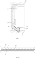
- FIG. 1 shows a partial sectional view of the sealing device according to the embodiment.
- the sealing device is in an annular shape as a whole. Shown in FIG. 1 is a representative part of a section passing through a central axis of the annular shape.
- the sealing device is installed in an annular space between two sealed parts.
- the two sealed parts may be, for example, an outer ring 10 and an inner ring 20 of a bearing.
- the outer ring 10 and the inner ring 20 are basically arranged around a common rotation axis and can relatively rotate around the rotation axis, wherein the outer ring 10 is located on a radial outer side of the inner ring 20.
- the central axis of the sealing device is arranged basically coincident with the rotation axis of the bearing.
- the sealing device may comprise a rigid annular member 30 and an annular elastic seal body 40.
- the rigid annular member 30 and the elastic seal body 40 are coaxially disposed around the rotation axis.
- the elastic seal body 40 is fixed to the rigid annular member 30.
- the rigid annular member 30 may be made of plastic materials.
- the plastic materials here may be various plastics having suitable mechanical properties, for example, PA 66.
- the plastic materials have sufficient stiffness to provide structural supporting for the elastic seal body 40; and on the other hand, the plastic materials are low-cost and easy to process, for example, various required shapes can be conveniently formed through injection molding.
- the rigid annular member 30 may also be made of metal materials.
- the rigid annular member 30 may be fixed to a radial inner side of the outer ring 10 in, for example, an interference fit manner, thereby being able to rotate together with the outer ring 10 relative to the inner ring 20.
- the elastic seal body 40 may be made of elastic materials such as rubber.
- the elastic seal body 40 comprises a base 41 and at least one seal lip 42.
- the seal lip 42 extends from the base 41 in a direction away from the base 41.
- the seal lip 42 of the elastic seal body 40 is an annular structure around the rotation axis.
- the base 41 and the seal lip 42 may be integrally formed.
- one seal lip 42 is schematically shown. In an installed state, the seal lip 42 extends toward the inner ring 20 on the radial inner side and contacts an outer surface of the inner ring 20 to form sealing fit.
- the elastic seal body 40 together with the rigid annular member 30 fixed thereto may rotate along with the outer ring 10 relative to the inner ring 20, thereby enabling the sealing device to dynamically seal an annular gap between the outer ring 10 and the inner ring 20.
- the seal lip 42 further comprises a foamed layer 43 formed on a surface thereof, and the foamed layer 43 has a plurality of foam structures 431.
- a foaming agent is sprayed to an inner surface of a vulcanization mold to form a plurality of foam structures 431 on the surface of the seal lip 42, thereby forming the foamed layer 43.
- the seal lip 42 and the foamed layer 43 may be integrally formed.
- FIG. 2A shows a partial sectional view of the seal lip 42 according to an embodiment of the present invention.
- the foam structures 431 are convex structures protruding from the surface of the seal lip 42. It should be understood that FIG. 2A only exemplarily shows that the plurality of foam structures 431 are distributed on the surface of the seal lip 42; and the plurality of foam structures 431 may be of unequal size, and the plurality of foam structures 431 may be unevenly and randomly distributed on the surface of the seal lip 42.
- FIG. 2B shows a partial sectional view of the seal lip 42 according to another embodiment of the present invention.
- the foam structures 431 are hole structures recessed in the surface of the seal lip 42. It should be understood that FIG. 2B only exemplarily shows that the plurality of foam structures 431 are distributed on the surface of the seal lip 42; and the plurality of foam structures 431 may be of unequal size, and the plurality of foam structures 431 may be unevenly and randomly distributed on the surface of the seal lip 42.
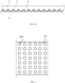
- FIG. 3 shows a partial top view of the foamed layer 43 according to an embodiment of the present invention.
- the plurality of foam structures 431 are distributed on the surface of the seal lip 42 to form the foamed layer 43. It should be understood that FIG. 3 only exemplarily shows that the plurality of foam structures 431 are distributed on the surface of the seal lip 42; and the plurality of foam structures 431 may be of unequal size, and the plurality of foam structures 431 may be unevenly and randomly distributed on the surface of the seal lip 42.
- the seal lip 42 further comprises a wear-resistant coating 44 formed on the foamed layer 43.
- a wear-resistant paint is applied on the foamed layer 43 to form the wear-resistant coating 44.
- the wear-resistant paint may be polytetrafluoroethylene (PTFE).
- PTFE polytetrafluoroethylene
- the PTFE has good wear resistance and can reduce the friction coefficient and friction torque on the surface of the seal lip 42 and improve the sealing performance of the sealing device.
- a portion of the wear-resistant coating 44 is among a plurality of foam structures 431 being convex structures, or, in another embodiment as shown in FIG. 2B , a portion of the wear-resistant coating 44 enters a plurality of foam structures 431 being hole structures, enabling the wear-resistant paint and the surface of the seal lip 42 to fully mix and permeate, thereby greatly improving the binding performance between the elastic seal body and the wear-resistant coating, and further making the binding between the elastic seal body and the wear-resistant coating more stable and reliable.
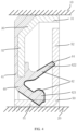
- FIG. 4 shows a partial sectional view of a sealing device according to another embodiment of the present invention.
- the sealing device may further comprise an oil retainer 50.
- the oil retainer 50 may be fixed to a radial outer side of the inner ring 20 in, for example, an interference fit manner, the oil retainer 50 and the rigid annular member 30 are substantially disposed oppositely in an axial direction, and the oil retainer 50 is rotatable around the rotation axis relative to the rigid annular member 30.
- the oil retainer 50 may be made of rigid materials, such as plastic materials or metal materials.
- the plastic materials here may also be various plastics having suitable mechanical properties, for example, PA 66.
- one end, away from the base 41, of the seal lip 42 may be in sealing fit with the oil retainer 50.
- the rigid annular member 30 comprises an annular member axial segment 31 generally extending along the axial direction and an annular member radial segment 32 generally extending along the radial direction, wherein the annular member axial segment 31 is used for fixing the rigid annular member 30 to the radial inner side of the outer ring 10, and the annular member radial segment 32 is used for fixing the base 41 of the elastic seal body 40.
- the oil retainer 50 comprises an oil retainer axial segment 51 generally extending along the axial direction and an oil retainer radial segment 52 generally extending along the radial direction, wherein the oil retainer axial segment 51 is used for fixing the oil retainer 50 to the radial outer side of the inner ring 20.
- annular member axial segment 31 and the oil retainer axial segment 51 are disposed oppositely in the radial direction
- the annular member radial segment 32 and the oil retainer radial segment 52 are disposed oppositely in the axial direction
- rigid annular member 30 and the oil retainer 50 form a chamber structure.
- one end, away from the base 41, of the at least one seal lip 42 may be in sealing fit with the oil retainer axial segment 51 and/or the oil retainer radial segment 52.
- the seal lip 42 comprises a main seal lip 421 and a centrifugal seal lip 422; and the main seal lip 421 is in sealing fit with the oil retainer axial segment 51, and the centrifugal seal lip 422 is in sealing fit with the oil retainer radial segment 52.
- the elastic seal body 40 may also have more or less seal lips, and these seal lips may also have different extending directions.
- a manufacturing method for a sealing device is used for manufacturing the sealing device as described above.
- the method comprises:
- the foaming agent may be an organic foaming agent such as azodicarbonamide (AC), p-toluenesulfonhydrazide (TSH), or an inorganic foaming agent such as sodium bicarbonate.
- organic foaming agent such as azodicarbonamide (AC), p-toluenesulfonhydrazide (TSH), or an inorganic foaming agent such as sodium bicarbonate.
- the elastic seal body 40 By vulcanizing the elastic seal body 40 made of rubber materials, the elastic seal body 40 can have higher elasticity, heat resistance and tensile strength, and can be insoluble in organic solvents; and by spraying the foaming agent on the inner surface of the mold, the elastic seal body 40 may be softer and have a plurality of foam structures 431, and thus further absorb and store wear-resistant materials, enabling two materials to well mix and permeate, thereby greatly improving the binding performance between the elastic seal body and wear-resistant coating, and further making the binding between the elastic seal body and the wear-resistant coating more stable and reliable, so as to guarantee that the sealing device has a better sealing performance, a lower friction torque, and a longer service life.
- the present invention aims to improve the wear-resistant coating on the surface of the seal lip in the sealing device and the manufacturing method for the sealing device. Therefore, the technical solutions of the present invention may be applied to various sealing devices and are not limited to particular components of specific sealing devices shown in the embodiments.
- the above improvements may be made to all of the seal lips, or to only one or some of the seal lips; and for each seal lip, the above improvements may be made to the entire surface of the seal lip, or to a partial surface of the seal lip, for example, the portions, in contact with the sealed part or the oil retainer 50, of the surface of the seal lip.
- the present invention may also be applied to other sealing devices which are in a non-annular structure and used for dynamic sealing.
Landscapes
- Engineering & Computer Science (AREA)
- General Engineering & Computer Science (AREA)
- Mechanical Engineering (AREA)
- Physics & Mathematics (AREA)
- Fluid Mechanics (AREA)
- Sealing With Elastic Sealing Lips (AREA)
Abstract
Description
- The present invention relates to the technical field of sealing. In particular, the present invention relates to a sealing device for dynamic sealing and a manufacturing method for the sealing device.
- Sealing devices are needed to be installed in rotating components of many machines. Especially, in the field of wheel bearings of vehicles, dynamic sealing with high sealing performance and low friction torque are required. These sealing devices are usually in anza annular shape and comprise rigid annular members and elastic seal bodies. The rigid annular members are made of metal materials, so as to be fixed to the rotating components on radial outer sides in a tight fit (or known as interference fit) manner. The elastic seal bodies are fixed to the rigid annular members and extend out to form one or more seal lips. Wear-resistant materials, such as polytetrafluoroethylene (PTFE), are coated on surfaces of the seal lips.
- In the working process of bearings, the coated wear-resistant coatings are prone to fall off from the surfaces of the seal lips, causing the reduced working efficiency and the lowered sealing performance of the bearings. Therefore, how to bond the wear-resistant coatings and the seal lips reliably and stably is very important for the working efficiency of the bearings and the safety of entire vehicles.
- In order to solve the above technical problems, the present invention provides a sealing device and a manufacturing method therefor.
- In a first aspect, embodiments of the present invention provide a sealing device, comprising an annular elastic seal body and a rigid annular member, wherein the elastic seal body is fixed to the rigid annular member, the elastic seal body comprises a base and at least one seal lip, and the seal lip extends from the base in a direction away from the base; and the seal lip comprises a foamed layer formed on a surface thereof, the foamed layer has a plurality of foam structures, and the seal lip further comprises a wear-resistant coating formed on the foamed layer.
- According to one embodiment of the present invention, the sealing device further comprises an oil retainer; the oil retainer and the rigid annular member are disposed oppositely in an axial direction, and the oil retainer and the rigid annular member are relatively rotatable around a rotation axis; and one end, away from the base, of the seal lip is in sealing fit with the oil retainer.
- According to one embodiment of the present invention, the rigid annular member comprises an annular member axial segment and an annular member radial segment, and the oil retainer comprises an oil retainer axial segment and an oil retainer radial segment; and the annular member axial segment and the oil retainer axial segment are disposed oppositely in a radial direction, the annular member radial segment and the oil retainer radial segment are disposed oppositely in the axial direction, and the rigid annular member and the oil retainer form a chamber structure.
- According to one embodiment of the present invention, the seal lip comprises a main seal lip and a centrifugal seal lip; and the main seal lip is in sealing fit with the oil retainer axial segment, and the centrifugal seal lip is in sealing fit with the oil retainer radial segment.
- According to one embodiment of the present invention, the foam structures are convex structures protruding from the surface of the seal lip; or the foam structures are hole structures recessed in the surface of the seal lip.
- According to one embodiment of the present invention, the seal lip and the foamed layer are integrally formed.
- According to one embodiment of the present invention, the base and the seal lip are integrally formed.
- According to one embodiment of the present invention, the wear-resistant coating is made of polytetrafluoroethylene (PTFE) materials.
- According to one embodiment of the present invention, the elastic seal body is made of rubber materials.
- In a second aspect, embodiments of the present invention provide a manufacturing method for a sealing device, wherein the sealing device comprises an annular elastic seal body and a rigid annular member, wherein the elastic seal body is fixed to the rigid annular member, the elastic seal body comprises a base and at least one seal lip, and the seal lip extends from the base in a direction away from the base; the seal lip comprises a foamed layer formed on a surface thereof, the foamed layer has a plurality of foam structures, and the seal lip further comprises a wear-resistant coating formed on the foamed layer; and the method comprises: vulcanizing the elastic seal body, wherein the surface of the seal lip is foamed by spraying a foaming agent on an inner surface of a mold, thereby forming the foamed layer; and forming the wear-resistant coating by applying a wear-resistant paint on the foamed layer.
- According to the sealing device and the manufacturing method therefor provided by the embodiments of the present invention, by means of vulcanizing the elastic seal body, wherein the surface of the seal lip is foamed by spraying the foaming agent to the surface of the mold, thereby forming the foamed layer, foamed rubber thus has characteristics of soft porous or multi-foam structures; when a wear-resistant paint is applied on the foamed layer, such soft porous or multi-foam structures can absorb and store wear-resistant materials to enable two materials to well mix and permeate, thereby greatly improving the binding performance between the elastic seal body and the wear-resistant coating, and further making the binding between the elastic seal body and the wear-resistant coating more stable and reliable, so as to guarantee that the sealing device has a better sealing performance, a lower friction torque, and a longer service life.
- In order to explain the technical solutions of the embodiments of the present invention more clearly, the accompanying drawings needed to be used in the description of the embodiments of the present invention will be briefly introduced below. Obviously, the accompanying drawings in the following description are only some embodiments of the present invention, and for those of ordinary skill in the art, other accompanying drawings can also be obtained based on these accompanying drawings without exerting creative efforts.
-
FIG. 1 shows a partial sectional view of a sealing device according to an embodiment of the present invention; -
FIG. 2A shows a partial sectional view of a seal lip according to an embodiment of the present invention; -
FIG. 2B shows a partial sectional view of a seal lip according to another embodiment of the present invention; -
FIG. 3 shows a partial top view of a foamed layer according to an embodiment of the present invention; and -
FIG. 4 shows a partial sectional view of a sealing device according to another embodiment of the present invention. - In order to make purposes, technical solutions and advantages of the embodiments of the present disclosure clearer, the technical solutions of the embodiments of the present disclosure will be clearly and completely described below in conjunction with the accompanying drawings of the embodiments of the present disclosure. Obviously, the described embodiments are some, but not all, of the embodiments of the present invention. Based on the described embodiments of the present invention, all other embodiments obtained by those of ordinary skill in the art fall within the scope of protection of the present invention.
- According to an embodiment of the present invention, provided is a sealing device. Such sealing device is used for sealing between various rotating components that need to be sealed. For example, it can be installed between an outer ring and an inner ring of a bearing, or installed between a bearing and a rotating shaft. The sealing device can seal, for example, lubricating oil and the like inside, and block contaminants such as muddy water outside.
-
FIG. 1 shows a partial sectional view of the sealing device according to the embodiment. The sealing device is in an annular shape as a whole. Shown inFIG. 1 is a representative part of a section passing through a central axis of the annular shape. As shown inFIG. 1 , the sealing device is installed in an annular space between two sealed parts. In the present embodiment, the two sealed parts may be, for example, anouter ring 10 and aninner ring 20 of a bearing. Theouter ring 10 and theinner ring 20 are basically arranged around a common rotation axis and can relatively rotate around the rotation axis, wherein theouter ring 10 is located on a radial outer side of theinner ring 20. The central axis of the sealing device is arranged basically coincident with the rotation axis of the bearing. - As shown in
FIG. 1 , the sealing device may comprise a rigidannular member 30 and an annularelastic seal body 40. The rigidannular member 30 and theelastic seal body 40 are coaxially disposed around the rotation axis. Theelastic seal body 40 is fixed to the rigidannular member 30. - The rigid
annular member 30 may be made of plastic materials. The plastic materials here may be various plastics having suitable mechanical properties, for example, PA 66. On one hand, the plastic materials have sufficient stiffness to provide structural supporting for theelastic seal body 40; and on the other hand, the plastic materials are low-cost and easy to process, for example, various required shapes can be conveniently formed through injection molding. Furthermore, the rigidannular member 30 may also be made of metal materials. In the present embodiment, the rigidannular member 30 may be fixed to a radial inner side of theouter ring 10 in, for example, an interference fit manner, thereby being able to rotate together with theouter ring 10 relative to theinner ring 20. - The
elastic seal body 40 may be made of elastic materials such as rubber. Theelastic seal body 40 comprises abase 41 and at least oneseal lip 42. Theseal lip 42 extends from thebase 41 in a direction away from thebase 41. Theseal lip 42 of theelastic seal body 40 is an annular structure around the rotation axis. Thebase 41 and theseal lip 42 may be integrally formed. In the embodiment shown inFIG. 1 , oneseal lip 42 is schematically shown. In an installed state, theseal lip 42 extends toward theinner ring 20 on the radial inner side and contacts an outer surface of theinner ring 20 to form sealing fit. Theelastic seal body 40 together with the rigidannular member 30 fixed thereto may rotate along with theouter ring 10 relative to theinner ring 20, thereby enabling the sealing device to dynamically seal an annular gap between theouter ring 10 and theinner ring 20. - Further, in conjunction with
FIG. 1 to FIG. 3 , theseal lip 42 further comprises a foamedlayer 43 formed on a surface thereof, and the foamedlayer 43 has a plurality offoam structures 431. In the process of vulcanizing theelastic seal body 40, a foaming agent is sprayed to an inner surface of a vulcanization mold to form a plurality offoam structures 431 on the surface of theseal lip 42, thereby forming the foamedlayer 43. Theseal lip 42 and the foamedlayer 43 may be integrally formed. - Specifically,
FIG. 2A shows a partial sectional view of theseal lip 42 according to an embodiment of the present invention. Thefoam structures 431 are convex structures protruding from the surface of theseal lip 42. It should be understood thatFIG. 2A only exemplarily shows that the plurality offoam structures 431 are distributed on the surface of theseal lip 42; and the plurality offoam structures 431 may be of unequal size, and the plurality offoam structures 431 may be unevenly and randomly distributed on the surface of theseal lip 42. -
FIG. 2B shows a partial sectional view of theseal lip 42 according to another embodiment of the present invention. Thefoam structures 431 are hole structures recessed in the surface of theseal lip 42. It should be understood thatFIG. 2B only exemplarily shows that the plurality offoam structures 431 are distributed on the surface of theseal lip 42; and the plurality offoam structures 431 may be of unequal size, and the plurality offoam structures 431 may be unevenly and randomly distributed on the surface of theseal lip 42. -
FIG. 3 shows a partial top view of the foamedlayer 43 according to an embodiment of the present invention. The plurality offoam structures 431 are distributed on the surface of theseal lip 42 to form the foamedlayer 43. It should be understood thatFIG. 3 only exemplarily shows that the plurality offoam structures 431 are distributed on the surface of theseal lip 42; and the plurality offoam structures 431 may be of unequal size, and the plurality offoam structures 431 may be unevenly and randomly distributed on the surface of theseal lip 42. - Further, referring to
FIG. 2A andFIG. 2B , theseal lip 42 further comprises a wear-resistant coating 44 formed on the foamedlayer 43. A wear-resistant paint is applied on the foamedlayer 43 to form the wear-resistant coating 44. The wear-resistant paint may be polytetrafluoroethylene (PTFE). The PTFE has good wear resistance and can reduce the friction coefficient and friction torque on the surface of theseal lip 42 and improve the sealing performance of the sealing device. - In the embodiment as shown in
FIG. 2A , a portion of the wear-resistant coating 44 is among a plurality offoam structures 431 being convex structures, or, in another embodiment as shown inFIG. 2B , a portion of the wear-resistant coating 44 enters a plurality offoam structures 431 being hole structures, enabling the wear-resistant paint and the surface of theseal lip 42 to fully mix and permeate, thereby greatly improving the binding performance between the elastic seal body and the wear-resistant coating, and further making the binding between the elastic seal body and the wear-resistant coating more stable and reliable. - Optionally,
FIG. 4 shows a partial sectional view of a sealing device according to another embodiment of the present invention. The sealing device may further comprise anoil retainer 50. Theoil retainer 50 may be fixed to a radial outer side of theinner ring 20 in, for example, an interference fit manner, theoil retainer 50 and the rigidannular member 30 are substantially disposed oppositely in an axial direction, and theoil retainer 50 is rotatable around the rotation axis relative to the rigidannular member 30. Theoil retainer 50 may be made of rigid materials, such as plastic materials or metal materials. The plastic materials here may also be various plastics having suitable mechanical properties, for example, PA 66. In addition, one end, away from thebase 41, of theseal lip 42 may be in sealing fit with theoil retainer 50. - Further, the rigid
annular member 30 comprises an annular memberaxial segment 31 generally extending along the axial direction and an annularmember radial segment 32 generally extending along the radial direction, wherein the annular memberaxial segment 31 is used for fixing the rigidannular member 30 to the radial inner side of theouter ring 10, and the annularmember radial segment 32 is used for fixing thebase 41 of theelastic seal body 40. Theoil retainer 50 comprises an oil retaineraxial segment 51 generally extending along the axial direction and an oilretainer radial segment 52 generally extending along the radial direction, wherein the oil retaineraxial segment 51 is used for fixing theoil retainer 50 to the radial outer side of theinner ring 20. The annular memberaxial segment 31 and the oil retaineraxial segment 51 are disposed oppositely in the radial direction, the annularmember radial segment 32 and the oilretainer radial segment 52 are disposed oppositely in the axial direction, and the rigidannular member 30 and theoil retainer 50 form a chamber structure. - In addition, one end, away from the
base 41, of the at least oneseal lip 42 may be in sealing fit with the oil retaineraxial segment 51 and/or the oilretainer radial segment 52. In the present embodiment, as shown inFIG. 4 , theseal lip 42 comprises amain seal lip 421 and acentrifugal seal lip 422; and themain seal lip 421 is in sealing fit with the oil retaineraxial segment 51, and thecentrifugal seal lip 422 is in sealing fit with the oilretainer radial segment 52. However, this is only illustrative, theelastic seal body 40 may also have more or less seal lips, and these seal lips may also have different extending directions. - According to an embodiment of the present invention, provided is a manufacturing method for a sealing device. The method is used for manufacturing the sealing device as described above. The method comprises:
- vulcanizing the
elastic seal body 40, wherein a surface of aseal lip 42 is foamed by spraying a foaming agent on an inner surface of a mold, thereby forming a foamedlayer 43; and - applying a wear-resistant paint on the foamed
layer 43 to form the wear-resistant coating 44. - The foaming agent may be an organic foaming agent such as azodicarbonamide (AC), p-toluenesulfonhydrazide (TSH), or an inorganic foaming agent such as sodium bicarbonate.
- By vulcanizing the
elastic seal body 40 made of rubber materials, theelastic seal body 40 can have higher elasticity, heat resistance and tensile strength, and can be insoluble in organic solvents; and by spraying the foaming agent on the inner surface of the mold, theelastic seal body 40 may be softer and have a plurality offoam structures 431, and thus further absorb and store wear-resistant materials, enabling two materials to well mix and permeate, thereby greatly improving the binding performance between the elastic seal body and wear-resistant coating, and further making the binding between the elastic seal body and the wear-resistant coating more stable and reliable, so as to guarantee that the sealing device has a better sealing performance, a lower friction torque, and a longer service life. - It should be noted that the present invention aims to improve the wear-resistant coating on the surface of the seal lip in the sealing device and the manufacturing method for the sealing device. Therefore, the technical solutions of the present invention may be applied to various sealing devices and are not limited to particular components of specific sealing devices shown in the embodiments. For a sealing device having a plurality of seal lips, the above improvements may be made to all of the seal lips, or to only one or some of the seal lips; and for each seal lip, the above improvements may be made to the entire surface of the seal lip, or to a partial surface of the seal lip, for example, the portions, in contact with the sealed part or the
oil retainer 50, of the surface of the seal lip. In addition, the present invention may also be applied to other sealing devices which are in a non-annular structure and used for dynamic sealing. - Although possible embodiments have been described illustratively in the above description, it should be understood that there are still a large number of embodiment variations through combinations of all known technical features and embodiments as well as those are readily apparent to those skilled in the art. In addition, it should be further understood that the exemplary embodiments are just examples and shall not in any way limit the scope of protection, application and construction of the present invention. The foregoing description is more intended to provide those skilled in the art with a technical guide for converting at least one exemplary embodiment, in which various changes, especially changes in the functions and structures of the components, can be made as long as they do not depart from the scope of protection of the claims.
-
- 10
- Outer ring
- 20
- Inner ring
- 30
- Rigid annular member
- 31
- Annular member axial segment
- 32
- Annular member radial segment
- 40
- Elastic seal body
- 41
- Base
- 42
- Seal lip
- 421
- Main seal lip
- 422
- Centrifugal seal lip
- 43
- Foamed layer
- 431
- Foam structure
- 44
- Wear-resistant coating
- 50
- Oil retainer
- 51
- Oil retainer axial segment
- 52
- Oil retainer radial segment
Claims (10)
- A sealing device, comprising an annular elastic seal body (40) and a rigid annular member (30), the elastic seal body (40) being fixed to the rigid annular member (30), whereinthe elastic seal body (40) comprises a base (41) and at least one seal lip (42), the seal lip (42) extends from the base (41) in a direction away from the base (41); andthe seal lip (42) comprises a foamed layer (43) formed on a surface thereof, the foamed layer (43) has a plurality of foam structures (431), and the seal lip (42) further comprises a wear-resistant coating (44) formed on the foamed layer (43).
- The sealing device according to Claim 1, wherein the sealing device further comprises an oil retainer (50);the oil retainer (50) and the rigid annular member (30) are disposed oppositely in an axial direction, and the oil retainer (50) and the rigid annular member (30) are relatively rotatable around a rotation axis; andone end, away from the base (41), of the seal lip (42) is in sealing fit with the oil retainer.
- The sealing device according to Claim 2, whereinthe rigid annular member (30) comprises an annular member axial segment (31) and an annular member radial segment (32), and the oil retainer (50) comprises an oil retainer axial segment (51) and an oil retainer radial segment (52); andthe annular member axial segment (31) and the oil retainer axial segment (51) are disposed oppositely in a radial direction, the annular member radial segment (32) and the oil retainer radial segment (52) are disposed oppositely in the axial direction, and the rigid annular member (30) and the oil retainer (50) form a chamber structure.
- The sealing device according to Claim 3, whereinthe seal lip (42) comprises a main seal lip (421) and a centrifugal seal lip (422); andthe main seal lip (421) is in sealing fit with the oil retainer axial segment (51), and the centrifugal seal lip (422) is in sealing fit with the oil retainer radial segment (52).
- The sealing device according to Claim 1, whereinthe foam structures (431) are convex structures protruding from the surface of the seal lip (42); orthe foam structures (431) are hole structures recessed in the surface of the seal lip (42).
- The sealing device according to Claim 1, wherein the seal lip (42) and the foamed layer (43) are integrally formed.
- The sealing device according to Claim 1, wherein the base (41) and the seal lip (42) are integrally formed.
- The sealing device according to Claim 1, wherein the wear-resistant coating (44) is made of polytetrafluoroethylene (PTFE) materials.
- The sealing device according to Claim 1, wherein the elastic seal body (40) is made of rubber materials.
- A manufacturing method for a sealing device, wherein the sealing device comprises an annular elastic seal body (40) and a rigid annular member (30), the elastic seal body (40) is fixed to the rigid annular member (30), the elastic seal body (40) comprises a base (41) and at least one seal lip (42), and the seal lip (42) extends from the base (41) in a direction away from the base (41); and the seal lip comprises a foamed layer (43) formed on a surface thereof, the foamed layer (43) has a plurality of foam structures (431), and the seal lip further comprises a wear-resistant coating (44) formed on the foamed layer (43); the method comprises:vulcanizing the elastic seal body (40), wherein the surface of the seal lip is foamed by spraying a foaming agent on an inner surface of a mold, thereby forming the foamed layer (43); andforming the wear-resistant coating (44) by applying a wear-resistant paint on the foamed layer (43).
Applications Claiming Priority (2)
| Application Number | Priority Date | Filing Date | Title |
|---|---|---|---|
| CN202111085416.4A CN115823256A (en) | 2021-09-16 | 2021-09-16 | Sealing device and manufacturing method thereof |
| PCT/CN2022/103066 WO2023040418A1 (en) | 2021-09-16 | 2022-06-30 | Sealing device and manufacturing method therefor |
Publications (2)
| Publication Number | Publication Date |
|---|---|
| EP4403803A1 true EP4403803A1 (en) | 2024-07-24 |
| EP4403803A4 EP4403803A4 (en) | 2025-07-09 |
Family
ID=85515002
Family Applications (1)
| Application Number | Title | Priority Date | Filing Date |
|---|---|---|---|
| EP22868795.0A Pending EP4403803A4 (en) | 2021-09-16 | 2022-06-30 | SEALING DEVICE AND MANUFACTURING METHOD THEREFOR |
Country Status (5)
| Country | Link |
|---|---|
| US (1) | US20240426378A1 (en) |
| EP (1) | EP4403803A4 (en) |
| KR (1) | KR20240042025A (en) |
| CN (1) | CN115823256A (en) |
| WO (1) | WO2023040418A1 (en) |
Family Cites Families (14)
| Publication number | Priority date | Publication date | Assignee | Title |
|---|---|---|---|---|
| US3521890A (en) * | 1968-10-07 | 1970-07-28 | Thiokol Chemical Corp | Quick change lip seal cartridge device |
| JPH0249429B2 (en) * | 1982-04-30 | 1990-10-30 | Nitto Denko Corp | SHIIRUZAI |
| AU5426200A (en) * | 1999-06-18 | 2001-01-09 | Nok Corporation | Lip-type high-pressure seal |
| JP4408559B2 (en) * | 2000-12-19 | 2010-02-03 | 西川ゴム工業株式会社 | Weatherstrip manufacturing method |
| DE10246398A1 (en) * | 2002-10-04 | 2004-04-29 | Ina-Schaeffler Kg | Shaft lip seal |
| US20080100003A1 (en) * | 2006-10-30 | 2008-05-01 | Dennis R Vance | Biased wall seals for extension unit |
| DE102008039805A1 (en) * | 2008-08-19 | 2010-02-25 | Kaco Gmbh + Co. Kg | Sealing ring i.e. radial shaft seal ring, has sealing lip with rear conveying device for medium to be sealed, and coating applied on sealing part for forming rear conveying device, which is provided at side that is turned away from medium |
| WO2012152808A1 (en) * | 2011-05-12 | 2012-11-15 | Aktiebolaget Skf | Texturized seal |
| WO2012168354A1 (en) * | 2011-06-07 | 2012-12-13 | Aktiebolaget Skf | Improved seal |
| DE102014012290A1 (en) * | 2014-08-22 | 2016-02-25 | Carl Freudenberg Kg | Sealing ring and its use |
| JP2018112235A (en) * | 2017-01-11 | 2018-07-19 | Ntn株式会社 | Linear ball bearing |
| CN207864626U (en) * | 2017-11-29 | 2018-09-14 | 舍弗勒技术股份两合公司 | Seal and seal assembly |
| CN110307341A (en) * | 2019-06-25 | 2019-10-08 | 舍弗勒技术股份两合公司 | Sealing means |
| CN214999393U (en) * | 2021-06-28 | 2021-12-03 | 厦门裕成祥工贸有限公司 | Anti-corrosion rubber Y-shaped rubber pad |
-
2021
- 2021-09-16 CN CN202111085416.4A patent/CN115823256A/en active Pending
-
2022
- 2022-06-30 US US18/684,865 patent/US20240426378A1/en active Pending
- 2022-06-30 EP EP22868795.0A patent/EP4403803A4/en active Pending
- 2022-06-30 WO PCT/CN2022/103066 patent/WO2023040418A1/en not_active Ceased
- 2022-06-30 KR KR1020247007383A patent/KR20240042025A/en active Pending
Also Published As
| Publication number | Publication date |
|---|---|
| CN115823256A (en) | 2023-03-21 |
| KR20240042025A (en) | 2024-04-01 |
| US20240426378A1 (en) | 2024-12-26 |
| WO2023040418A1 (en) | 2023-03-23 |
| EP4403803A4 (en) | 2025-07-09 |
Similar Documents
| Publication | Publication Date | Title |
|---|---|---|
| US7448807B2 (en) | Seal | |
| US6213476B1 (en) | Bi-modulus composite seal and its method of manufacture | |
| US20100066030A1 (en) | Hermetic sealing device | |
| WO2008024152A2 (en) | Spherical roller bearing sealing assembly | |
| US20130101242A1 (en) | Seal arrangement | |
| EP4403803A1 (en) | Sealing device and manufacturing method therefor | |
| CN214197001U (en) | Combined bearing | |
| CN101026322A (en) | Lubricant retention assembly | |
| CN114673791A (en) | Sealing means | |
| US10428868B2 (en) | Ball bearing assembly | |
| RU2693394C1 (en) | Hinge of equal angular speeds with direct fastening of driving gear | |
| JP2009250285A (en) | Roller bearing and one-way clutch | |
| CN105042082A (en) | Self-sealing full-polytetrafluoroethylene oil seal with monitoring function | |
| JP7527930B2 (en) | Sealing device | |
| KR102536974B1 (en) | Wheel bearing having improved sealing structure | |
| CN202091516U (en) | Oil seal of automobile hub | |
| CN114165524A (en) | Conducting ring | |
| KR20250120383A (en) | Wheel bearing units, especially for automotive use | |
| CN222277212U (en) | Four-point contact release bearing unit | |
| CN120384961A (en) | Sealing device, manufacturing method thereof, and bearing device | |
| JPH09144761A (en) | Ball bearing, and pulley and fan provided with the ball bearing | |
| CN117062993A (en) | Seal assemblies and rolling bearings including such assemblies | |
| CN217234120U (en) | Double-row ball three-layer sealed agricultural machinery bearing unit | |
| US20240416678A1 (en) | Vehicular wheel bearing comprising sealing device having internal pressure discharging portion | |
| CN121322535A (en) | Sealing assembly for joint bearing |
Legal Events
| Date | Code | Title | Description |
|---|---|---|---|
| STAA | Information on the status of an ep patent application or granted ep patent |
Free format text: STATUS: THE INTERNATIONAL PUBLICATION HAS BEEN MADE |
|
| PUAI | Public reference made under article 153(3) epc to a published international application that has entered the european phase |
Free format text: ORIGINAL CODE: 0009012 |
|
| STAA | Information on the status of an ep patent application or granted ep patent |
Free format text: STATUS: REQUEST FOR EXAMINATION WAS MADE |
|
| 17P | Request for examination filed |
Effective date: 20240416 |
|
| AK | Designated contracting states |
Kind code of ref document: A1 Designated state(s): AL AT BE BG CH CY CZ DE DK EE ES FI FR GB GR HR HU IE IS IT LI LT LU LV MC MK MT NL NO PL PT RO RS SE SI SK SM TR |
|
| DAV | Request for validation of the european patent (deleted) | ||
| DAX | Request for extension of the european patent (deleted) | ||
| A4 | Supplementary search report drawn up and despatched |
Effective date: 20250610 |
|
| RIC1 | Information provided on ipc code assigned before grant |
Ipc: F16J 15/3204 20160101ALI20250603BHEP Ipc: F16J 15/324 20160101ALI20250603BHEP Ipc: F16J 15/3236 20160101ALI20250603BHEP Ipc: F16J 15/3244 20160101ALI20250603BHEP Ipc: F16J 15/3264 20160101ALI20250603BHEP Ipc: B29L 31/00 20060101ALI20250603BHEP Ipc: B29C 44/04 20060101ALI20250603BHEP Ipc: B29C 44/12 20060101ALI20250603BHEP Ipc: B29C 44/06 20060101ALI20250603BHEP Ipc: F16J 15/3268 20160101ALI20250603BHEP Ipc: F16J 15/3284 20160101ALI20250603BHEP Ipc: F16J 15/3232 20160101AFI20250603BHEP |