EP4403757A1 - Radiator control system for a work vehicle and control method for a work vehicle - Google Patents
Radiator control system for a work vehicle and control method for a work vehicle Download PDFInfo
- Publication number
- EP4403757A1 EP4403757A1 EP24152250.7A EP24152250A EP4403757A1 EP 4403757 A1 EP4403757 A1 EP 4403757A1 EP 24152250 A EP24152250 A EP 24152250A EP 4403757 A1 EP4403757 A1 EP 4403757A1
- Authority
- EP
- European Patent Office
- Prior art keywords
- temperature
- work vehicle
- time interval
- fan
- cleaning time
- Prior art date
- Legal status (The legal status is an assumption and is not a legal conclusion. Google has not performed a legal analysis and makes no representation as to the accuracy of the status listed.)
- Pending
Links
Images

Classifications
-
- F—MECHANICAL ENGINEERING; LIGHTING; HEATING; WEAPONS; BLASTING
- F01—MACHINES OR ENGINES IN GENERAL; ENGINE PLANTS IN GENERAL; STEAM ENGINES
- F01P—COOLING OF MACHINES OR ENGINES IN GENERAL; COOLING OF INTERNAL-COMBUSTION ENGINES
- F01P7/00—Controlling of coolant flow
- F01P7/02—Controlling of coolant flow the coolant being cooling-air
- F01P7/06—Controlling of coolant flow the coolant being cooling-air by varying blade pitch
-
- F—MECHANICAL ENGINEERING; LIGHTING; HEATING; WEAPONS; BLASTING
- F01—MACHINES OR ENGINES IN GENERAL; ENGINE PLANTS IN GENERAL; STEAM ENGINES
- F01P—COOLING OF MACHINES OR ENGINES IN GENERAL; COOLING OF INTERNAL-COMBUSTION ENGINES
- F01P11/00—Component parts, details, or accessories not provided for in, or of interest apart from, groups F01P1/00 - F01P9/00
- F01P11/06—Cleaning; Combating corrosion
-
- F—MECHANICAL ENGINEERING; LIGHTING; HEATING; WEAPONS; BLASTING
- F01—MACHINES OR ENGINES IN GENERAL; ENGINE PLANTS IN GENERAL; STEAM ENGINES
- F01P—COOLING OF MACHINES OR ENGINES IN GENERAL; COOLING OF INTERNAL-COMBUSTION ENGINES
- F01P3/00—Liquid cooling
- F01P3/20—Cooling circuits not specific to a single part of engine or machine
-
- F—MECHANICAL ENGINEERING; LIGHTING; HEATING; WEAPONS; BLASTING
- F01—MACHINES OR ENGINES IN GENERAL; ENGINE PLANTS IN GENERAL; STEAM ENGINES
- F01P—COOLING OF MACHINES OR ENGINES IN GENERAL; COOLING OF INTERNAL-COMBUSTION ENGINES
- F01P7/00—Controlling of coolant flow
- F01P7/02—Controlling of coolant flow the coolant being cooling-air
- F01P7/08—Controlling of coolant flow the coolant being cooling-air by cutting in or out of pumps
-
- F—MECHANICAL ENGINEERING; LIGHTING; HEATING; WEAPONS; BLASTING
- F01—MACHINES OR ENGINES IN GENERAL; ENGINE PLANTS IN GENERAL; STEAM ENGINES
- F01P—COOLING OF MACHINES OR ENGINES IN GENERAL; COOLING OF INTERNAL-COMBUSTION ENGINES
- F01P5/00—Pumping cooling-air or liquid coolants
- F01P5/02—Pumping cooling-air; Arrangements of cooling-air pumps, e.g. fans or blowers
- F01P5/04—Pump-driving arrangements
- F01P5/043—Pump reversing arrangements
Definitions
- the present invention concerns a control system for a work vehicle, preferably an agricultural vehicle, such as a tractor.
- the present invention also relates to a work vehicle comprising a control system and to a control method for a work vehicle.
- Work vehicles are known to comprise one or more radiators, which allow certain parts (e.g., the engine and/or the transmission) of the work vehicles to be cooled down.
- the radiators comprise a bundle of tubes, which are internally crossed by a coolant and possibly equipped with fins.
- the tubes are impinged externally by an air flow due, by way of example, to the relative motion between the work vehicle and the air surrounding it, or the action of a fan positioned in proximity to the radiator(s).
- the airflow absorbs heat from the coolant flowing inside the tubes.
- the radiators of work vehicles are often exposed to the accumulation of contaminants (dust, debris, mud%) due to the working conditions they are subjected to. Such accumulation may result in a reduced thermal exchange between the coolant and the airflow and may cause overheating of the parts of the vehicle to be cooled.
- the fan of the work vehicles may be adapted to generate and orient a forced cleaning airflow towards the radiator.
- the forced airflow allows cleaning of the parts of the radiator that are exposed to the contaminants and the regions adjacent thereto.
- the cleaning operations of the radiators are performed automatically and regularly at predetermined time intervals and for a predetermined duration.
- the cleaning operations are controlled by the user. Therefore, there is a risk that the radiator is either cleaned too frequently or not cleaned frequently enough.
- the heat exchange efficiency of the radiator may be significantly affected by forced airflow from the fan. It is therefore of paramount importance that cleaning operations do not last so long as to risk overheating of the vehicle components.
- numeral 10 indicates a work vehicle, in particular an agricultural vehicle such as a tractor.
- cooling system 15 adapted to cool down one or more portions of the vehicle.
- cooling system 15 is adapted to cool down motor means 13 and/or transmission 14.
- Cooling system 15 in turn comprises a radiator 20 and a not-shown circuit, which fluidly connects the portion(s) of the vehicle to be cooled to radiator 20 and within which a coolant flows.
- radiator 20 comprises a bundle of tubes adapted to be internally crossed by the coolant flowing in the circuit and possibly equipped with fins.
- the tubes are adapted to be impinged externally by an air flow that absorbs heat from the coolant flowing within the tubes.
- the airflow may be due to the relative motion between work vehicle 10 and the air by which it is surrounded.
- Work vehicle 1 further comprises a fan 21 adapted to generate an air flow directed towards radiator 20 to perform a cleaning operation of radiator 20 ( Figure 1 ).
- fan 21 comprises a hub rotatable about a rotational axis thereof and a plurality of blades, which are constrained to the hub and extend trasversally to the rotational axis.
- the blades are articulated on the hub so as to be able to vary their orientation with respect to the hub and adjust their respective pitch angles.
- fan 21 is a variable-pitch fan and is adapted to vary the direction of the airflow directed towards radiator 20. More specifically, by varying the direction of the airflow, debris and contaminants may be removed from different portions of radiator 20. Alternatively, the same operation can be executed with a change of the rotation direction of fan 21.
- work vehicle 1 comprises a temperature sensor 22 adapted to periodically detect a temperature T of at least a portion of work vehicle 10.
- temperature sensor 22 is adapted to detect a temperature of motor means 13 or transmission 14.
- Work vehicle 10 further comprises a control system 1 configured to automatically control the cleaning operation of radiator 20.
- Control system 1 comprises, in turn, a control unit 2 operatively connected to temperature sensor 22 and fan 21.
- Control unit 2 is configured to activate fan 21, i.e., to command fan 21 to perform the cleaning operation of radiator 20, as a function of the detected temperature T.
- control unit 2 is also configured to command a variation of the pitch angle of the blades or rotation direction of fan 21, in order to vary the direction of the airflow generated by fan 21.
- control unit 2 is configured to command fan 21 to perform the cleaning operation of radiator 20 for a cleaning time interval, the duration of which is dependent on temperature T.
- control unit 2 is configured to activate fan 21 for a cleaning time interval having a duration equal at most to a first value D1.
- Temperature threshold T1 is the temperature above which the component to be cooled is considered to be in an overheated condition.
- the temperature threshold T1 is calculated by multiplying the temperature above which the component to be cooled is in the overheated condition by a safety factor.
- control unit 2 may be configured to activate fan 21 for a cleaning time interval of shorter duration than first value D1.
- control unit 2 is configured to deactivate fan 21, i.e. to disable cleaning operations of radiator 20.
- control unit 2 is configured to activate fan 21 for a cleaning time interval having a duration equal at most to a second value D2.
- the second value D2 is lower than or equal to the first value D1 and is set such that temperature T at the end of the cleaning time interval is equal to or lower than the temperature T detected at the start of the cleaning time interval.
- control unit 2 may be configured to activate fan 21 for a cleaning time interval of shorter duration than second value D2.
- second value D2 varies as a function of the detected temperature T. In further detail, the lower the detected temperature T, the greater the corresponding second value D2.
- Control system 1 further comprises a memory 3, which is adapted to store a relation holding between the detected temperature T and the preferred duration of the cleaning time interval.
- control unit 2 is configured to command fan 21 according to the relation stored in memory 3.
- the relation is stored in memory 3 in the form of tables and/or graphs that associate several temperature values with respective optimal durations of the cleaning interval.
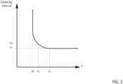
- Figure 2 shows the relation in the form of a graph having a preferred trend.
- the graph is a branch of an equilateral hyperbola in a Cartesian plane wherein the abscissa axis represents the values of detected temperature T and the ordinate axis represents the corresponding values D1 or D2 of cleaning time interval.
- Control system 1 further comprises a human-machine interface 4 operatively connected to control unit 2 ( Figure 1 ).
- the human-machine interface 4 is configured to receive, in use, a user's command to enable or disable the automatic cleaning operation of radiator 20.
- Human-machine interface 4 may be further configured to receive, in use, a user's command to manually trigger a cleaning operation of radiator 20.
- control unit 2 is configured to send an alert signal to human-machine interface 4 to warn the user that the components of work vehicle 1 to be cooled are close to the overheated condition, based on detected temperature T.
- control system 1 The operation of control system 1 according to the present invention is described in the following.
- temperature sensor 22 periodically detects temperature T. If the user has enabled the automatic cleaning operation of radiator 20, control unit 2 activates fan 21 as a function of the detected temperature T.
- control unit 2 activates fan 21 for a cleaning time interval having a duration equal at most to first value D1.
- control unit 2 completely disables cleaning operations of radiator 20.
- control unit 2 activates fan 21 for a cleaning time interval having a duration equal at most to second value D2.
- 10' denotes a work vehicle according to a second embodiment of the present invention.
- Work vehicle 10' is similar to work vehicle 10 and will be described hereinafter only insofar as it differs from the latter; equal or equivalent parts of work vehicles 10, 10' will be marked, where possible, by the same reference numerals.
- Work vehicle 10' differs from work vehicle 10 in that it comprises a control system 1' and two temperature sensors 22', 23', which are respectively adapted to detect the temperature T of motor means 13 and transmission 14.
- temperature sensor 22' is adapted to detect the temperature of a portion of motor means 13 or of a region of work vehicle 10 in proximity to motor means 13 or a mean temperature of motor means 13;
- temperature sensor 23' is adapted to detect the temperature of a portion of transmission 14 or of a region of work vehicle 10 in proximity to transmission 14 or a mean temperature of transmission 14.
- Control system 1' differs from control system 1 in that control unit 2 is configured to determine a first optimal duration of the cleaning time interval based on temperature T detected by temperature sensor 22' and a second optimal duration of the cleaning time interval based on temperature T detected by temperature sensor 23'. Control unit 2 is further configured to activate fan 21 for a cleaning time interval having a duration equal to the minimum of the first and second optimal durations.
- control unit 2 is configured to determine the first and the second optimal durations on the basis of the relation stored in memory 3. In further detail, control unit 2 is configured to compare each of the temperatures T detected by temperature sensors 22', 23' with temperature thresholds T1 and T0 and to associate the detected temperatures T with respective values of the cleaning time interval according to the relation.
- memory 3 is configured to store:
- control unit 2 is configured to determine the first and the second optimal durations on the basis of the respective first and second relations stored in memory 3. According to the not-shown embodiment, control unit 2 is further configured to activate fan 21 for a cleaning time interval having a duration equal to the minimum of the first and second optimal durations.
- control system 1' The operation of control system 1' according to the present invention is described in the following.
- temperature sensors 22', 23' periodically detect respective temperatures T. If the user has enabled the automatic cleaning operation of radiator 20, control unit 2 activates fan 21 as a function of the detected temperatures T.
- control unit 2 determines the first optimal duration of the cleaning time interval based on temperature T detected by temperature sensor 22' and the second optimal duration of the cleaning time interval based on temperature T detected by temperature sensor 23'. Control unit 2 then activates fan 21 for a cleaning time interval having a duration equal to the minimum of the first and second optimal durations.
- control system 1, 1' and the method of control of work vehicle 10; 10' according to the invention are apparent.
- control unit 2 is configured to command fan 21 to perform the cleaning operation based on detected temperature(s) T and for a cleaning time interval, the duration of which is dependent on detected temperature(s) T, the cleaning operations of radiator 20 can be efficiently and automatically carried out.
- control unit 2 is configured to deactivate fan 21 when temperature T is equal to or lower than temperature threshold T0, the automatic cleaning operation of radiator 20 is automatically disabled when the risk of work vehicle components overheating due to the accumulation of contaminants on radiator 20 is minimal.
- control system 1; 1', work vehicle 10; 10' and the method of control of work vehicle 10; 10' which do not extend beyond the scope of protection defined by the claims.
- temperature sensors 22, 23 may be adapted to detect the temperature of an engine coolant, an engine oil and/or a transmission oil.
Landscapes
- Engineering & Computer Science (AREA)
- Chemical & Material Sciences (AREA)
- Combustion & Propulsion (AREA)
- Mechanical Engineering (AREA)
- General Engineering & Computer Science (AREA)
- Cooling, Air Intake And Gas Exhaust, And Fuel Tank Arrangements In Propulsion Units (AREA)
Abstract
Description
- The present invention concerns a control system for a work vehicle, preferably an agricultural vehicle, such as a tractor. The present invention also relates to a work vehicle comprising a control system and to a control method for a work vehicle.
- Work vehicles are known to comprise one or more radiators, which allow certain parts (e.g., the engine and/or the transmission) of the work vehicles to be cooled down.
- In general, the radiators comprise a bundle of tubes, which are internally crossed by a coolant and possibly equipped with fins. During operation, the tubes are impinged externally by an air flow due, by way of example, to the relative motion between the work vehicle and the air surrounding it, or the action of a fan positioned in proximity to the radiator(s). The airflow absorbs heat from the coolant flowing inside the tubes.
- The radiators of work vehicles, particularly agricultural vehicles, are often exposed to the accumulation of contaminants (dust, debris, mud...) due to the working conditions they are subjected to. Such accumulation may result in a reduced thermal exchange between the coolant and the airflow and may cause overheating of the parts of the vehicle to be cooled.
- In light of this, the fan of the work vehicles may be adapted to generate and orient a forced cleaning airflow towards the radiator. The forced airflow allows cleaning of the parts of the radiator that are exposed to the contaminants and the regions adjacent thereto.
- In known work vehicles, the cleaning operations of the radiators are performed automatically and regularly at predetermined time intervals and for a predetermined duration. Alternatively, the cleaning operations are controlled by the user. Therefore, there is a risk that the radiator is either cleaned too frequently or not cleaned frequently enough.
- Furthermore, during the cleaning operation of the radiator, the heat exchange efficiency of the radiator may be significantly affected by forced airflow from the fan. It is therefore of paramount importance that cleaning operations do not last so long as to risk overheating of the vehicle components.
- Therefore, there is a need within the industry for a control system for a work vehicle allowing the cleaning operation of the radiator to be efficiently and automatically carried out.
- The aforementioned aim is reached by a control system for a work vehicle and by a control method for a work vehicle, as claimed in the appended independent claims.
- Preferred embodiments of the invention are realized according to the claims dependent or related to the above independent claims.
- For a better understanding of the present invention, two preferred embodiments are described in the following, by way of a non-limiting example, with reference to the attached drawings wherein:
-
Figure 1 is a lateral view of a work vehicle according to a first embodiment of the present invention, comprising a schematic representation of a control system; -
Figure 2 is a plot illustrating the duration of a cleaning interval commanded by the control system ofFigure 1 as a function of a detected temperature; -
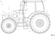
Figure 3 a lateral view of a work vehicle according to a second embodiment of the present invention, comprising a schematic representation of a control system. - With reference to
figure 1 ,numeral 10 indicates a work vehicle, in particular an agricultural vehicle such as a tractor. -
Work vehicle 10 comprises amain body 11, a plurality ofwheels 12, which are rotatable relative tomain body 11 about respective rotational axes and motor means 13 (e.g., a thermal engine and/or an electric motor) adapted to rotatewheels 12 about their respective rotational axes.Work vehicle 10 further comprises a transmission 14 (only schematically shown), which operatively connects motor means 13 towheels 12. - Furthermore,
work vehicle 10 comprises acooling system 15 adapted to cool down one or more portions of the vehicle. By way of example,cooling system 15 is adapted to cool down motor means 13 and/ortransmission 14.Cooling system 15 in turn comprises aradiator 20 and a not-shown circuit, which fluidly connects the portion(s) of the vehicle to be cooled toradiator 20 and within which a coolant flows. - In detail,
radiator 20 comprises a bundle of tubes adapted to be internally crossed by the coolant flowing in the circuit and possibly equipped with fins. The tubes are adapted to be impinged externally by an air flow that absorbs heat from the coolant flowing within the tubes. In further detail, the airflow may be due to the relative motion betweenwork vehicle 10 and the air by which it is surrounded. -
Work vehicle 1 further comprises afan 21 adapted to generate an air flow directed towardsradiator 20 to perform a cleaning operation of radiator 20 (Figure 1 ). - In detail,
fan 21 comprises a hub rotatable about a rotational axis thereof and a plurality of blades, which are constrained to the hub and extend trasversally to the rotational axis. Preferably, the blades are articulated on the hub so as to be able to vary their orientation with respect to the hub and adjust their respective pitch angles. In other words,fan 21 is a variable-pitch fan and is adapted to vary the direction of the airflow directed towardsradiator 20. More specifically, by varying the direction of the airflow, debris and contaminants may be removed from different portions ofradiator 20. Alternatively, the same operation can be executed with a change of the rotation direction offan 21. - In addition,
work vehicle 1 comprises atemperature sensor 22 adapted to periodically detect a temperature T of at least a portion ofwork vehicle 10. In detail,temperature sensor 22 is adapted to detect a temperature of motor means 13 ortransmission 14. -
Work vehicle 10 further comprises acontrol system 1 configured to automatically control the cleaning operation ofradiator 20.Control system 1 comprises, in turn, acontrol unit 2 operatively connected totemperature sensor 22 andfan 21.Control unit 2 is configured to activatefan 21, i.e., to commandfan 21 to perform the cleaning operation ofradiator 20, as a function of the detected temperature T. Preferably,control unit 2 is also configured to command a variation of the pitch angle of the blades or rotation direction offan 21, in order to vary the direction of the airflow generated byfan 21. - Advantageously,
control unit 2 is configured to commandfan 21 to perform the cleaning operation ofradiator 20 for a cleaning time interval, the duration of which is dependent on temperature T. - In particular, if the detected temperature T is equal to or greater than a temperature threshold T1,
control unit 2 is configured to activatefan 21 for a cleaning time interval having a duration equal at most to a first value D1. Temperature threshold T1 is the temperature above which the component to be cooled is considered to be in an overheated condition. Alternatively, the temperature threshold T1 is calculated by multiplying the temperature above which the component to be cooled is in the overheated condition by a safety factor. - The first value D1 is set such that temperature T at the end of the cleaning time interval is equal to or lower than temperature threshold T1. Specifically, first value D1 is chosen so that temperature T detected at the end of the cleaning time interval of duration D1 is not greater than the temperature T measured at the start of the cleaning time interval.
- More specifically, if the detected temperature T is equal to or greater than temperature threshold T1,
control unit 2 may be configured to activatefan 21 for a cleaning time interval of shorter duration than first value D1. - If the detected temperature T is equal to or lower than a temperature threshold T0, which is lower than temperature threshold T1,
control unit 2 is configured to deactivatefan 21, i.e. to disable cleaning operations ofradiator 20. - If the detected temperature T is greater than temperature threshold T0 and lower than temperature threshold T1,
control unit 2 is configured to activatefan 21 for a cleaning time interval having a duration equal at most to a second value D2. The second value D2 is lower than or equal to the first value D1 and is set such that temperature T at the end of the cleaning time interval is equal to or lower than the temperature T detected at the start of the cleaning time interval. - More specifically, if the detected temperature T is greater than temperature threshold T0 and lower than temperature threshold T1,
control unit 2 may be configured to activatefan 21 for a cleaning time interval of shorter duration than second value D2. - In detail, second value D2 varies as a function of the detected temperature T. In further detail, the lower the detected temperature T, the greater the corresponding second value D2.
-
Control system 1 further comprises amemory 3, which is adapted to store a relation holding between the detected temperature T and the preferred duration of the cleaning time interval. In particular,control unit 2 is configured to commandfan 21 according to the relation stored inmemory 3. - The relation is stored in
memory 3 in the form of tables and/or graphs that associate several temperature values with respective optimal durations of the cleaning interval. -
Figure 2 shows the relation in the form of a graph having a preferred trend. In particular, the graph is a branch of an equilateral hyperbola in a Cartesian plane wherein the abscissa axis represents the values of detected temperature T and the ordinate axis represents the corresponding values D1 or D2 of cleaning time interval. -
Control system 1 further comprises a human-machine interface 4 operatively connected to control unit 2 (Figure 1 ). The human-machine interface 4 is configured to receive, in use, a user's command to enable or disable the automatic cleaning operation ofradiator 20. Human-machine interface 4 may be further configured to receive, in use, a user's command to manually trigger a cleaning operation ofradiator 20. - Preferably,
control unit 2 is configured to send an alert signal to human-machine interface 4 to warn the user that the components ofwork vehicle 1 to be cooled are close to the overheated condition, based on detected temperature T. - The operation of
control system 1 according to the present invention is described in the following. - In use,
temperature sensor 22 periodically detects temperature T. If the user has enabled the automatic cleaning operation ofradiator 20,control unit 2 activatesfan 21 as a function of the detected temperature T. - In detail, if the detected temperature T is equal to or greater than temperature threshold T1,
control unit 2 activatesfan 21 for a cleaning time interval having a duration equal at most to first value D1. - If the detected temperature T is equal to or lower than temperature threshold
T0 control unit 2 completely disables cleaning operations ofradiator 20. - If the detected temperature T is greater than temperature threshold T0 and lower than temperature threshold T1,
control unit 2 activatesfan 21 for a cleaning time interval having a duration equal at most to second value D2. - With reference to
Figure 3 , 10' denotes a work vehicle according to a second embodiment of the present invention. Work vehicle 10' is similar to workvehicle 10 and will be described hereinafter only insofar as it differs from the latter; equal or equivalent parts ofwork vehicles 10, 10' will be marked, where possible, by the same reference numerals. - Work vehicle 10' differs from
work vehicle 10 in that it comprises a control system 1' and two temperature sensors 22', 23', which are respectively adapted to detect the temperature T of motor means 13 andtransmission 14. In further detail, temperature sensor 22' is adapted to detect the temperature of a portion of motor means 13 or of a region ofwork vehicle 10 in proximity to motor means 13 or a mean temperature of motor means 13; temperature sensor 23' is adapted to detect the temperature of a portion oftransmission 14 or of a region ofwork vehicle 10 in proximity totransmission 14 or a mean temperature oftransmission 14. - Control system 1' differs from
control system 1 in thatcontrol unit 2 is configured to determine a first optimal duration of the cleaning time interval based on temperature T detected by temperature sensor 22' and a second optimal duration of the cleaning time interval based on temperature T detected by temperature sensor 23'.Control unit 2 is further configured to activatefan 21 for a cleaning time interval having a duration equal to the minimum of the first and second optimal durations. - In detail,
control unit 2 is configured to determine the first and the second optimal durations on the basis of the relation stored inmemory 3. In further detail,control unit 2 is configured to compare each of the temperatures T detected by temperature sensors 22', 23' with temperature thresholds T1 and T0 and to associate the detected temperatures T with respective values of the cleaning time interval according to the relation. - According to a not-shown embodiment,
memory 3 is configured to store: - a first relation, which associates several temperature values of the temperature T detected by temperature sensor 22' with respective first optimal durations of the cleaning time interval;
- a second relation, which associates several temperature values of the temperature T detected by temperature sensor 23' with respective second optimal durations of the cleaning time interval.
- According to this not-shown embodiment,
control unit 2 is configured to determine the first and the second optimal durations on the basis of the respective first and second relations stored inmemory 3. According to the not-shown embodiment,control unit 2 is further configured to activatefan 21 for a cleaning time interval having a duration equal to the minimum of the first and second optimal durations. - The operation of control system 1' according to the present invention is described in the following.
- In use, temperature sensors 22', 23' periodically detect respective temperatures T. If the user has enabled the automatic cleaning operation of
radiator 20,control unit 2 activatesfan 21 as a function of the detected temperatures T. - In detail,
control unit 2 determines the first optimal duration of the cleaning time interval based on temperature T detected by temperature sensor 22' and the second optimal duration of the cleaning time interval based on temperature T detected by temperature sensor 23'.Control unit 2 then activatesfan 21 for a cleaning time interval having a duration equal to the minimum of the first and second optimal durations. - In view of the foregoing, the advantages of
control system 1, 1' and the method of control ofwork vehicle 10; 10' according to the invention are apparent. - In detail, since
control unit 2 is configured to commandfan 21 to perform the cleaning operation based on detected temperature(s) T and for a cleaning time interval, the duration of which is dependent on detected temperature(s) T, the cleaning operations ofradiator 20 can be efficiently and automatically carried out. - Since the optimal duration of the cleaning interval is calculated according to a predetermined relation, cleaning operations do not last so long as to risk overheating of the vehicle components.
- Since
control unit 2 is configured to deactivatefan 21 when temperature T is equal to or lower than temperature threshold T0, the automatic cleaning operation ofradiator 20 is automatically disabled when the risk of work vehicle components overheating due to the accumulation of contaminants onradiator 20 is minimal. - It is clear that modifications can be made to control
system 1; 1',work vehicle 10; 10' and the method of control ofwork vehicle 10; 10' which do not extend beyond the scope of protection defined by the claims. - In particular,
work vehicle 10; 10' might comprise more than oneradiator 20 and/or more than twotemperature sensors 22, 23. - Alternatively or in addition,
temperature sensors 22, 23 may be adapted to detect the temperature of an engine coolant, an engine oil and/or a transmission oil.
Claims (14)
- Control system for a work vehicle (10; 10'); said work vehicle (10; 10') comprising:- a radiator (20);- a fan (21) adapted to generate an air flow directed towards said radiator (20) to perform, in use, a cleaning operation of said radiator (20);- at least one temperature sensor (22; 22', 23') adapted to detect a temperature (T) of a portion of said work vehicle (10) ;said control system (1; 1') comprising a control unit (2) adapted to be operatively connected to said at least one temperature sensor (22; 22', 23') and said fan (21);wherein said control unit (2) is configured to command said fan (21) to perform, in use, said cleaning operation based on said temperature (T) and for a cleaning time interval, the duration of which is dependent on said temperature (T).
- Control system according to claim 1, wherein said control unit (2) is configured to activate said fan (21) for said cleaning time interval having a duration equal at most to a first value (D1) when, in use, said temperature (T) is equal to or greater than a first temperature threshold (T1);
wherein said first value (D1) is set such that said temperature (T) at the end of said cleaning time interval is equal to or lower than said first temperature threshold (T1). - Control system according to claim 2, wherein said control unit (2) is configured to deactivate said fan (21) when, in use, said temperature (T) is equal to or lower than a second temperature threshold (T0); said second temperature threshold (T0) being lower than said first temperature threshold (T1).
- Control system according to claim 3, wherein said control unit (2) is configured to activate said fan (21) for said cleaning time interval having a duration equal at most to a second value (D2) when, in use, said temperature (T) is greater than said second temperature threshold (T0) and lower than said first temperature threshold (T1);wherein said second value (D2) is set such that said temperature (T) detected, in use, at the end of said cleaning time interval is equal to or lower than said temperature (T) detected, in use, at the start of said cleaning time interval;wherein said second value (D2) is lower than or equal to said first value (D1).
- Control system according to claim 4, said second value (D2) is variable as a function of said temperature (T);
wherein the lower said temperature (T), the greater said second value (D2). - Control system according to any one of the foregoing claims, comprising a memory (3) adapted to store a relation holding between said temperature (T) and the duration of said cleaning time interval.
- Control system according to claim 6, wherein a graph of said relation is a branch of an equilateral hyperbola in a Cartesian plane with one of the two Cartesian axes representing said temperature (T) and the other one of the two Cartesian axes representing said first and second values (D1, D2) .
- Control system according to any one of the foregoing claims, comprising a human-machine interface (4) operatively connected to said control unit (2);
said human-machine interface (4) being configured to receive, in use, a user's command to enable or disable the operation of said fan (21). - Control system according to any one of the foregoing claims, wherein said work vehicle (10; 10') comprises a first temperature sensor (22') and a second temperature sensor (23'), said first and second temperature sensors (22', 23') being adapted to detect respective temperatures (T) of respective portions of said work vehicle (10');said control unit (2) being configured to determine a first duration of said cleaning time interval based on said temperature (T) detected by said first temperature sensor (22') and a second duration of said cleaning time interval based on said temperature (T) detected by said second temperature sensor (23');said control unit (2) being further configured to activate said fan (21) for a cleaning time interval having a duration equal to the minimum of said first and second durations.
- Work vehicle (10; 10') comprising:- a radiator (20);- a fan (21) adapted to generate an air flow directed towards said radiator (20) to perform, in use, a cleaning operation of said radiator (20);- at least one temperature sensor (22; 22', 23') adapted to detect a temperature (T) of a portion of said work vehicle (10); and- a control system (1; 1') according to any one of the foregoing claims.
- Work vehicle according to claim 10, wherein said fan (21) is a variable-pitch fan.
- Work vehicle according to claim 10 or 11, comprising:- a first temperature sensor (22') and a second temperature sensor (23'); said first and second temperature sensors (22', 23') being adapted to detect respective temperatures (T) of respective portions of said work vehicle (10'); and- a control system (1') according to claim 9.
- Method of control of a work vehicle (10), comprising the steps of:i) detecting a temperature (T) of at least a portion of said work vehicle (10) by a temperature sensor (22; 22', 23') of said work vehicle (10);ii) commanding a cleaning operation of a radiator (20) of said work vehicle (10) based on said temperature (T) detected at said step i); said cleaning operation being performed by generating an air flow directed towards said radiator (20) by means of a fan (21) of said work vehicle (1);wherein said cleaning operation is performed for a cleaning time interval, the duration of which is dependent on said temperature (T).
- Method of control according to claim 13, wherein said cleaning time interval has a duration equal at most to a first value (D1) when said temperature (T) is equal to or greater than a first temperature threshold (T1); said first value (D1) being set such that said temperature (T) at the end of said cleaning time interval is equal to or lower than said first temperature threshold (T1);
wherein said cleaning time interval has a duration equal at most to a second value (D2) when said temperature (T) is greater than a second temperature threshold (T0) and lower than said first temperature threshold (T1); said second temperature threshold (T0) being lower than said first temperature threshold (T1); wherein said second value (D2) is set such that said temperature (T) detected at the end of said cleaning time interval is equal to or lower than said temperature (T) detected at the start of said cleaning time interval; wherein said second value (D2) is lower than or equal to said first value (D1).
Applications Claiming Priority (1)
| Application Number | Priority Date | Filing Date | Title |
|---|---|---|---|
| IT102023000000582A IT202300000582A1 (en) | 2023-01-17 | 2023-01-17 | RADIATOR CONTROL SYSTEM FOR A WORK VEHICLE AND CONTROL METHOD FOR A WORK VEHICLE |
Publications (1)
| Publication Number | Publication Date |
|---|---|
| EP4403757A1 true EP4403757A1 (en) | 2024-07-24 |
Family
ID=85685671
Family Applications (1)
| Application Number | Title | Priority Date | Filing Date |
|---|---|---|---|
| EP24152250.7A Pending EP4403757A1 (en) | 2023-01-17 | 2024-01-16 | Radiator control system for a work vehicle and control method for a work vehicle |
Country Status (2)
| Country | Link |
|---|---|
| EP (1) | EP4403757A1 (en) |
| IT (1) | IT202300000582A1 (en) |
Citations (3)
| Publication number | Priority date | Publication date | Assignee | Title |
|---|---|---|---|---|
| EP1696112A1 (en) * | 2005-02-25 | 2006-08-30 | Jtekt HPI | Method and system for controlling the reversing of the direction of rotation of a hydraulic motor |
| EP3236040A1 (en) * | 2016-04-11 | 2017-10-25 | Deere & Company | Air cleaning arrangement for a work vehicle |
| EP3575568A1 (en) * | 2017-09-26 | 2019-12-04 | Hitachi Construction Machinery Co., Ltd. | Work vehicle |
-
2023
- 2023-01-17 IT IT102023000000582A patent/IT202300000582A1/en unknown
-
2024
- 2024-01-16 EP EP24152250.7A patent/EP4403757A1/en active Pending
Patent Citations (3)
| Publication number | Priority date | Publication date | Assignee | Title |
|---|---|---|---|---|
| EP1696112A1 (en) * | 2005-02-25 | 2006-08-30 | Jtekt HPI | Method and system for controlling the reversing of the direction of rotation of a hydraulic motor |
| EP3236040A1 (en) * | 2016-04-11 | 2017-10-25 | Deere & Company | Air cleaning arrangement for a work vehicle |
| EP3575568A1 (en) * | 2017-09-26 | 2019-12-04 | Hitachi Construction Machinery Co., Ltd. | Work vehicle |
Also Published As
| Publication number | Publication date |
|---|---|
| IT202300000582A1 (en) | 2024-07-17 |
Similar Documents
| Publication | Publication Date | Title |
|---|---|---|
| CN110549840B (en) | An electric drive engineering machinery cooling system and its control method and control device | |
| US5889376A (en) | Motor driving apparatus | |
| US6655326B2 (en) | ECU temperature control | |
| EP3077639B1 (en) | Vehicle cooling system | |
| US7631618B2 (en) | Damage protected motor vehicle fan | |
| US11181034B2 (en) | Cooling system | |
| US5564899A (en) | Engine cooling system with blade angle controllable cooling fan | |
| CN112031919B (en) | Engine cooling control method with double alarm functions | |
| EP2943664B1 (en) | Control of cooling fan based on electrical current | |
| US20200130096A1 (en) | Methods and apparatus for multi-directional fan | |
| JPH11117799A (en) | Engine cooling system failure detection device | |
| KR102925006B1 (en) | Combine having turning direction cooling fan | |
| KR100730825B1 (en) | Cooling fan motor driving device of construction equipment | |
| IT202300000582A1 (en) | RADIATOR CONTROL SYSTEM FOR A WORK VEHICLE AND CONTROL METHOD FOR A WORK VEHICLE | |
| CN118926652A (en) | Electric welding machine control method, electric welding machine control device and electric welding machine | |
| CN208380686U (en) | Engine-cooling system and vehicle | |
| JPH10259726A (en) | Hydraulic fan drive system | |
| CN107842416B (en) | A kind of truck is cooling with noise balance control system and control method | |
| JP2017100702A (en) | Control apparatus and control method for vehicular compressor | |
| KR200329885Y1 (en) | Radiator debris removal device | |
| SE1050432A1 (en) | Cooling and heating systems | |
| JP4337212B2 (en) | Cooling device for liquid-cooled internal combustion engine | |
| JP4478069B2 (en) | Fan clutch control device | |
| CN121105669A (en) | A self-cleaning method and system for vehicle cooling systems and new energy vehicles | |
| KR200235613Y1 (en) | Motor cooling device using thermoelectric element |
Legal Events
| Date | Code | Title | Description |
|---|---|---|---|
| PUAI | Public reference made under article 153(3) epc to a published international application that has entered the european phase |
Free format text: ORIGINAL CODE: 0009012 |
|
| STAA | Information on the status of an ep patent application or granted ep patent |
Free format text: STATUS: THE APPLICATION HAS BEEN PUBLISHED |
|
| AK | Designated contracting states |
Kind code of ref document: A1 Designated state(s): AL AT BE BG CH CY CZ DE DK EE ES FI FR GB GR HR HU IE IS IT LI LT LU LV MC ME MK MT NL NO PL PT RO RS SE SI SK SM TR |
|
| STAA | Information on the status of an ep patent application or granted ep patent |
Free format text: STATUS: REQUEST FOR EXAMINATION WAS MADE |
|
| 17P | Request for examination filed |
Effective date: 20250124 |
|
| STAA | Information on the status of an ep patent application or granted ep patent |
Free format text: STATUS: EXAMINATION IS IN PROGRESS |
|
| 17Q | First examination report despatched |
Effective date: 20250917 |
|
| GRAP | Despatch of communication of intention to grant a patent |
Free format text: ORIGINAL CODE: EPIDOSNIGR1 |
|
| STAA | Information on the status of an ep patent application or granted ep patent |
Free format text: STATUS: GRANT OF PATENT IS INTENDED |
|
| INTG | Intention to grant announced |
Effective date: 20260626 |