EP4403747A1 - Turbine nozzle with dust tolerant impingement cooling - Google Patents
Turbine nozzle with dust tolerant impingement cooling Download PDFInfo
- Publication number
- EP4403747A1 EP4403747A1 EP23220212.7A EP23220212A EP4403747A1 EP 4403747 A1 EP4403747 A1 EP 4403747A1 EP 23220212 A EP23220212 A EP 23220212A EP 4403747 A1 EP4403747 A1 EP 4403747A1
- Authority
- EP
- European Patent Office
- Prior art keywords
- apertures
- surface portion
- wall
- tube
- turbine vane
- Prior art date
- Legal status (The legal status is an assumption and is not a legal conclusion. Google has not performed a legal analysis and makes no representation as to the accuracy of the status listed.)
- Pending
Links
Images






Classifications
-
- F—MECHANICAL ENGINEERING; LIGHTING; HEATING; WEAPONS; BLASTING
- F01—MACHINES OR ENGINES IN GENERAL; ENGINE PLANTS IN GENERAL; STEAM ENGINES
- F01D—NON-POSITIVE DISPLACEMENT MACHINES OR ENGINES, e.g. STEAM TURBINES
- F01D5/00—Blades; Blade-carrying members; Heating, heat-insulating, cooling or antivibration means on the blades or the members
- F01D5/12—Blades
- F01D5/14—Form or construction
- F01D5/18—Hollow blades, i.e. blades with cooling or heating channels or cavities; Heating, heat-insulating or cooling means on blades
- F01D5/186—Film cooling
-
- F—MECHANICAL ENGINEERING; LIGHTING; HEATING; WEAPONS; BLASTING
- F01—MACHINES OR ENGINES IN GENERAL; ENGINE PLANTS IN GENERAL; STEAM ENGINES
- F01D—NON-POSITIVE DISPLACEMENT MACHINES OR ENGINES, e.g. STEAM TURBINES
- F01D5/00—Blades; Blade-carrying members; Heating, heat-insulating, cooling or antivibration means on the blades or the members
- F01D5/12—Blades
- F01D5/14—Form or construction
- F01D5/18—Hollow blades, i.e. blades with cooling or heating channels or cavities; Heating, heat-insulating or cooling means on blades
- F01D5/187—Convection cooling
- F01D5/188—Convection cooling with an insert in the blade cavity to guide the cooling fluid, e.g. forming a separation wall
- F01D5/189—Convection cooling with an insert in the blade cavity to guide the cooling fluid, e.g. forming a separation wall the insert having a tubular cross-section, e.g. airfoil shape
-
- F—MECHANICAL ENGINEERING; LIGHTING; HEATING; WEAPONS; BLASTING
- F01—MACHINES OR ENGINES IN GENERAL; ENGINE PLANTS IN GENERAL; STEAM ENGINES
- F01D—NON-POSITIVE DISPLACEMENT MACHINES OR ENGINES, e.g. STEAM TURBINES
- F01D9/00—Stators
- F01D9/02—Nozzles; Nozzle boxes; Stator blades; Guide conduits, e.g. individual nozzles
- F01D9/04—Nozzles; Nozzle boxes; Stator blades; Guide conduits, e.g. individual nozzles forming ring or sector
- F01D9/041—Nozzles; Nozzle boxes; Stator blades; Guide conduits, e.g. individual nozzles forming ring or sector using blades
-
- F—MECHANICAL ENGINEERING; LIGHTING; HEATING; WEAPONS; BLASTING
- F01—MACHINES OR ENGINES IN GENERAL; ENGINE PLANTS IN GENERAL; STEAM ENGINES
- F01D—NON-POSITIVE DISPLACEMENT MACHINES OR ENGINES, e.g. STEAM TURBINES
- F01D9/00—Stators
- F01D9/06—Fluid supply conduits to nozzles or the like
- F01D9/065—Fluid supply or removal conduits traversing the working fluid flow, e.g. for lubrication-, cooling-, or sealing fluids
-
- F—MECHANICAL ENGINEERING; LIGHTING; HEATING; WEAPONS; BLASTING
- F01—MACHINES OR ENGINES IN GENERAL; ENGINE PLANTS IN GENERAL; STEAM ENGINES
- F01D—NON-POSITIVE DISPLACEMENT MACHINES OR ENGINES, e.g. STEAM TURBINES
- F01D5/00—Blades; Blade-carrying members; Heating, heat-insulating, cooling or antivibration means on the blades or the members
- F01D5/12—Blades
- F01D5/14—Form or construction
- F01D5/18—Hollow blades, i.e. blades with cooling or heating channels or cavities; Heating, heat-insulating or cooling means on blades
- F01D5/187—Convection cooling
-
- F—MECHANICAL ENGINEERING; LIGHTING; HEATING; WEAPONS; BLASTING
- F05—INDEXING SCHEMES RELATING TO ENGINES OR PUMPS IN VARIOUS SUBCLASSES OF CLASSES F01-F04
- F05D—INDEXING SCHEME FOR ASPECTS RELATING TO NON-POSITIVE-DISPLACEMENT MACHINES OR ENGINES, GAS-TURBINES OR JET-PROPULSION PLANTS
- F05D2250/00—Geometry
- F05D2250/30—Arrangement of components
- F05D2250/31—Arrangement of components according to the direction of their main axis or their axis of rotation
- F05D2250/311—Arrangement of components according to the direction of their main axis or their axis of rotation the axes being in line
-
- F—MECHANICAL ENGINEERING; LIGHTING; HEATING; WEAPONS; BLASTING
- F05—INDEXING SCHEMES RELATING TO ENGINES OR PUMPS IN VARIOUS SUBCLASSES OF CLASSES F01-F04
- F05D—INDEXING SCHEME FOR ASPECTS RELATING TO NON-POSITIVE-DISPLACEMENT MACHINES OR ENGINES, GAS-TURBINES OR JET-PROPULSION PLANTS
- F05D2250/00—Geometry
- F05D2250/30—Arrangement of components
- F05D2250/31—Arrangement of components according to the direction of their main axis or their axis of rotation
- F05D2250/312—Arrangement of components according to the direction of their main axis or their axis of rotation the axes being parallel to each other
-
- F—MECHANICAL ENGINEERING; LIGHTING; HEATING; WEAPONS; BLASTING
- F05—INDEXING SCHEMES RELATING TO ENGINES OR PUMPS IN VARIOUS SUBCLASSES OF CLASSES F01-F04
- F05D—INDEXING SCHEME FOR ASPECTS RELATING TO NON-POSITIVE-DISPLACEMENT MACHINES OR ENGINES, GAS-TURBINES OR JET-PROPULSION PLANTS
- F05D2250/00—Geometry
- F05D2250/50—Inlet or outlet
- F05D2250/52—Outlet
-
- F—MECHANICAL ENGINEERING; LIGHTING; HEATING; WEAPONS; BLASTING
- F05—INDEXING SCHEMES RELATING TO ENGINES OR PUMPS IN VARIOUS SUBCLASSES OF CLASSES F01-F04
- F05D—INDEXING SCHEME FOR ASPECTS RELATING TO NON-POSITIVE-DISPLACEMENT MACHINES OR ENGINES, GAS-TURBINES OR JET-PROPULSION PLANTS
- F05D2250/00—Geometry
- F05D2250/70—Shape
- F05D2250/71—Shape curved
- F05D2250/711—Shape curved convex
-
- F—MECHANICAL ENGINEERING; LIGHTING; HEATING; WEAPONS; BLASTING
- F05—INDEXING SCHEMES RELATING TO ENGINES OR PUMPS IN VARIOUS SUBCLASSES OF CLASSES F01-F04
- F05D—INDEXING SCHEME FOR ASPECTS RELATING TO NON-POSITIVE-DISPLACEMENT MACHINES OR ENGINES, GAS-TURBINES OR JET-PROPULSION PLANTS
- F05D2250/00—Geometry
- F05D2250/70—Shape
- F05D2250/71—Shape curved
- F05D2250/712—Shape curved concave
-
- F—MECHANICAL ENGINEERING; LIGHTING; HEATING; WEAPONS; BLASTING
- F05—INDEXING SCHEMES RELATING TO ENGINES OR PUMPS IN VARIOUS SUBCLASSES OF CLASSES F01-F04
- F05D—INDEXING SCHEME FOR ASPECTS RELATING TO NON-POSITIVE-DISPLACEMENT MACHINES OR ENGINES, GAS-TURBINES OR JET-PROPULSION PLANTS
- F05D2260/00—Function
- F05D2260/20—Heat transfer, e.g. cooling
- F05D2260/201—Heat transfer, e.g. cooling by impingement of a fluid
Definitions
- the present disclosure generally relates to gas turbine engines, and more particularly relates to a turbine nozzle associated with a turbine of a gas turbine engine having a turbine vane airfoil with dust tolerant impingement cooling.
- Gas turbine engines may be employed to power various devices.
- a gas turbine engine may be employed to power a mobile platform, such as an aircraft.
- the gas turbine engine may ingest fine sand and dust particles during operation. These ingested fine sand and dust particles may pass through portions of the gas turbine engine and may accumulate in stagnation regions of cooling circuits within turbine components, such as the airfoils of a turbine vane associated with a turbine nozzle.
- the accumulation of the fine sand and dust particles in the stagnation regions of the cooling circuits in the turbine components, such as the airfoil, may impede the cooling of the airfoil, which in turn, may reduce the life of the airfoil and the turbine nozzle leading to increased repair costs and downtime for the gas turbine engine.
- a turbine vane airfoil for a turbine nozzle.
- the turbine vane airfoil includes an airfoil defining a chamber proximate a surface, and an impingement tube configured to be disposed in the chamber and configured to receive a cooling fluid.
- the impingement tube includes a first wall that is spaced apart from a second wall.
- the first wall defines a plurality of first apertures, and each of the plurality of first apertures has a first upstream surface portion opposite a first downstream surface portion in a flow direction of the cooling fluid into the impingement tube.
- the second wall defines a plurality of second apertures, and each of the plurality of second apertures has a second upstream surface portion opposite a second downstream surface portion.
- At least one of the plurality of first apertures has a first dimension between the first upstream surface portion and the first downstream surface portion that is greater than a second dimension between the second upstream surface portion and the second downstream surface portion of at least one of the plurality of second apertures.
- Each of the plurality of first apertures cooperate with a respective one of the plurality of second apertures to direct the cooling fluid onto the surface, and the first downstream surface portion of at least one of the plurality of first apertures includes a first point that is collinear with a second point of the second downstream surface portion of the respective one of the plurality of second apertures along a line, and the line is substantially parallel to a first centerline of the at least one of the plurality of first apertures.
- the at least one of the plurality of second apertures includes a second centerline, the first centerline is offset from the second centerline and the first centerline is substantially parallel to the second centerline.
- Each of the plurality of first apertures has a first geometry that is the same as a second geometry of each of the plurality of second apertures.
- Each of the plurality of first apertures has a first geometry that is different than a second geometry of each of the plurality of second apertures.
- At least one of the plurality of first apertures includes at least one convex surface.
- the at least one convex surface is defined at the first upstream surface portion.
- the at least one convex surface is defined at the first downstream surface portion.
- the at least one convex surface includes a pair of convex surfaces, with a first one of the pair of convex surfaces defined at the first upstream surface portion and a second one of the pair of convex surfaces defined at the first downstream surface portion.
- At least one of the plurality of first apertures includes at least one concave surface.
- the at least one concave surface is defined at the first upstream surface portion.
- At least one of the plurality of first apertures further comprises a pair of opposing sidewalls defined by a pair of arcuate surfaces.
- At least one of the plurality of first apertures further comprises a pair of opposing sidewalls defined by a pair of concave surfaces.
- the first upstream surface portion is defined by at least a concave surface and a convex surface.
- the first wall is an inner wall of the impingement tube
- the second wall is an outer wall of the impingement tube
- the second wall is positioned between the first wall and the surface.
- the surface is opposite a leading edge of the airfoil.
- the impingement tube includes a first tube body that includes the first wall, a second tube body that includes the second wall, the first tube body defines a plenum configured to receive the cooling fluid into the impingement tube, and the first tube body is coupled to the second tube body such that a tube chamber is defined between at least a portion of the first tube body and the second tube body.
- the turbine nozzle includes a turbine vane airfoil including an airfoil defining a chamber proximate a surface, and an impingement tube configured to be disposed in the chamber.
- the impingement tube includes a first tube body including a first wall and a second tube body including a second wall.
- the first tube body defines a plenum configured to receive a cooling fluid.
- the first wall is spaced apart from the second wall, and the first wall defines a plurality of first apertures. Each of the plurality of first apertures has a first upstream surface portion opposite a first downstream surface portion in a flow direction of the cooling fluid into the first tube body.
- the second wall defines a plurality of second apertures, and each of the plurality of second apertures has a second upstream surface portion opposite a second downstream surface portion. At least one of the plurality of first apertures has a first dimension between the first upstream surface portion and the first downstream surface portion that is greater than a second dimension between the second upstream surface portion and the second downstream surface portion of at least one of the plurality of second apertures. Each of the plurality of first apertures cooperate with a respective one of the plurality of second apertures to direct the cooling fluid onto the surface.
- the first downstream surface portion of at least one of the plurality of first apertures includes a first point that is collinear with a second point of the second downstream surface portion of the respective one of the plurality of second apertures along a line and the line is substantially parallel to a first centerline of the at least one of the plurality of first apertures.
- the at least one of the plurality of second apertures includes a second centerline, the first centerline is offset from the second centerline and the first centerline is substantially parallel to the second centerline.
- Each of the plurality of first apertures has a first geometry that is different than a second geometry of each of the plurality of second apertures.
- the first wall is an inner wall of the impingement tube
- the second wall is an outer wall of the impingement tube
- the second wall is positioned between the first wall and the surface
- the surface is opposite a leading edge of the airfoil.
- the term “axial” refers to a direction that is generally parallel to or coincident with an axis of rotation, axis of symmetry, or centerline of a component or components.
- the "axial" direction may refer to the direction that generally extends in parallel to the centerline between the opposite ends or faces.
- the term “axial” may be utilized with respect to components that are not cylindrical (or otherwise radially symmetric).
- the "axial" direction for a rectangular housing containing a rotating shaft may be viewed as a direction that is generally parallel to or coincident with the rotational axis of the shaft.
- radially may refer to a direction or a relationship of components with respect to a line extending outward from a shared centerline, axis, or similar reference, for example in a plane of a cylinder or disc that is perpendicular to the centerline or axis.
- components may be viewed as “radially” aligned even though one or both of the components may not be cylindrical (or otherwise radially symmetric).
- axial and radial (and any derivatives) may encompass directional relationships that are other than precisely aligned with (e.g., oblique to) the true axial and radial dimensions, provided the relationship is predominately in the respective nominal axial or radial direction.
- the term “substantially” denotes within 10% to account for manufacturing tolerances.
- the gas turbine engine 100 includes a turbine nozzle 200 ( FIG. 1A ), which has at least one turbine vane system or turbine vane airfoil 202 with dust tolerant impingement cooling.
- a turbine nozzle 200 FIG. 1A
- the turbine vane airfoil 202 By providing the turbine vane airfoil 202 with dust tolerant impingement cooling, the accumulation of fine sand and dust particles within the turbine vane airfoil 202 is reduced, which improves a life of the turbine nozzle 200.
- turbine nozzle 200 and the turbine vane airfoil 202 are illustrated and described herein as being used with the gas turbine engine 100, which can be included with an auxiliary power unit, the turbine nozzle 200 and/or the turbine vane airfoil 202 can be employed with various types of engines, including, but not limited to, turbofan, turboprop, turboshaft, and turbojet engines, whether deployed onboard an aircraft, watercraft, or ground vehicle (e.g., a tank), included within industrial power generators, or utilized within another platform or application.
- the gas turbine engine 100 is employed within an aircraft 99.
- the gas turbine engine 100 includes a fan section 12, a compressor section 14, a combustor section 16, a turbine section 18, and an exhaust section 10.
- the fan section 12 includes a fan 22 mounted on a rotor 24 that draws air into the gas turbine engine 100 and accelerates it. A fraction of the accelerated air exhausted from the fan 22 is directed through an outer (or first) bypass duct 26 and the remaining fraction of air exhausted from the fan 22 is directed into the compressor section 14.
- the outer bypass duct 26 is generally defined by an inner casing 28 and an outer casing 30.
- the compressor section 14 includes an intermediate pressure compressor 32 and a high pressure compressor 34. However, in other embodiments, the number of compressors in the compressor section 14 may vary.
- the intermediate pressure compressor 32 and the high pressure compressor 34 sequentially raise the pressure of the air and direct a majority of the high pressure air into the combustor section 16.
- a fraction of the compressed air bypasses the combustor section 16 and is used to cool, among other components, turbine blades in the turbine section 18.
- the high pressure air is mixed with fuel, which is combusted.
- the high-temperature combustion air is directed into the turbine section 18.
- the turbine section 18 includes three turbines disposed in axial flow series, namely, a high pressure turbine 104, an intermediate pressure turbine 40, and a low pressure turbine 42.
- the number of turbines, and/or the configurations thereof, may vary.
- the high-temperature air from the combustor section 16 is directed through the turbine nozzle 200 and expands through and rotates each turbine 104, 40, and 42.
- each drives equipment in the gas turbine engine 100 via concentrically disposed shafts or spools.
- the high pressure turbine 104 drives the high pressure compressor 34 via a high pressure shaft 44
- the intermediate pressure turbine 40 drives the intermediate pressure compressor 32 via an intermediate pressure shaft 46
- the low pressure turbine 42 drives the fan 22 via a low pressure shaft 48.
- the gas turbine engine 100 includes the turbine nozzle 200, as illustrated in accordance with an exemplary embodiment.
- the turbine nozzle 200 is a high pressure turbine nozzle.
- the illustrated portion of the gas turbine engine 100 further includes a downstream or outlet end of the combustor 102, the high pressure turbine 104, a surrounding turbine case 106, and a turbine shroud 108.
- the turbine nozzle 200, the outlet end of the combustor 102, the high pressure turbine 104, the turbine case 106 and the turbine shroud 108 are each generally axisymmetric about the centerline or rotational axis of the gas turbine engine 100, which is parallel to the X-axis identified by the coordinate legend 110.
- a core gas flow path 112 extends through the illustrated portions of the gas turbine engine 100 and is defined by the combustor 102, the turbine nozzle 200, the high pressure turbine 104, and the turbine shroud 108.
- combustive gasses are discharged from the combustor 102 and progress along the core gas flow path 112.
- the turbine nozzle 200 is positioned immediately downstream of the combustor 102 and upstream of the high pressure turbine 104.
- the turbine nozzle 200 receives the hot, combustive gas flow discharged by the combustor 102.
- the turbine nozzle 200 meters, accelerates, and turns the combustive gas flow toward a plurality of turbine blades 114 associated with the high pressure turbine 104.
- the combustive gas flow drives rotation of the high pressure turbine 104 and non-illustrated shaft or shafts associated with the gas turbine engine 100. This, in turn, drives the rotation of other non-illustrated components (e.g., a fan or compressor rotor) associated with the gas turbine engine 100 and provides power output, which may be extracted from the gas turbine engine 100 in different forms.
- non-illustrated components e.g., a fan or compressor rotor
- the turbine nozzle 200 includes an outer annular endwall 204 and an inner annular endwall 206, which are substantially concentric and radially spaced.
- the outer and inner annular endwalls 204, 206 bound inner and outer peripheries of the portion of the core gas flow path 112, which extends through the turbine nozzle 200.
- the turbine nozzle 200 also includes a number of the turbine vane airfoils 202, one of which can be seen in the cross-section of FIG. 1A .
- the turbine vane airfoils 202 are arranged in an annular array, which is located between the annular endwalls 204, 206.
- Each of the turbine vane airfoils 202 extends between the annular endwalls 204, 206 in a different radial direction similar to the spokes of a wheel; the term "radial direction” defined herein as a direction extending perpendicular to the centerline of the turbine nozzle 200 and the centerline or rotational axis of the gas turbine engine 100.
- the turbine vane airfoil 202 shown in FIG. 1A extends in a radial direction, which corresponds to the Y-axis of the coordinate legend 110.
- the axial direction is a direction perpendicular to the radial direction and parallel to the centerline of the turbine nozzle 200, and the axial direction corresponds to the X-axis of the coordinate legend 110.
- the Z-axis is perpendicular to the Y-axis and the X-axis.
- the turbine vane airfoil 202 is shown in a flattened or meridional state in the cross-sectional schematic of FIG. 1A .
- the turbine vane airfoil 202 includes an airfoil 208 and an impingement tube 210.
- the impingement tube 210 provides dust tolerant impingement cooling for the airfoil 208 of the turbine vane airfoil 202, and thus, the turbine nozzle 200.
- the airfoil 208 includes an internal chamber 212 ( FIG. 2 ), and the impingement tube 210 is inserted into the internal chamber 212 of the airfoil 208.
- Similar or identical impingement tubes are likewise inserted into the other non-illustrated airfoils 208 of turbine vane airfoils 202 associated with the turbine nozzle 200, which may be similar or identical to the illustrated turbine vane airfoil 202.
- the turbine nozzle 200 contains multiple impingement tubes 210, which are collectively arranged in an annular array that is substantially concentric with the centerline of the turbine nozzle 200.
- the following description will focus primarily on the illustrated turbine vane airfoil 202 shown in FIGS. 1A and 2 , and the illustrated impingement tube 210 shown in FIGS. 1A-8 ; however, the following description is equally applicable to the other non-illustrated impingement tubes and turbine vane airfoils included within the turbine nozzle 200.
- the impingement tube 210 is used to cool the airfoil 208 of the turbine vane airfoil 202 during operation of the gas turbine engine 100.
- the impingement tube 210 supports enhanced convective heat removal targeted at a leading edge portion 214 of the airfoil 208, which is primarily impinged by the combustive gas flow discharged from combustor 102 (represented by arrows 216).
- a secondary flow system directs relatively cool airflow or cooling fluid 220 into an outboard portion 218 of the impingement tube 210.
- a flow direction of the cooling fluid 220 into the impingement tube 210 is in the radial direction.
- the cooling fluid 220 flows through the impingement tube 210 and exits the impingement tube 210 to provide cooling to the leading edge portion 214 of the airfoil 208 ( FIG. 2A ).
- the impingement tube 210 directs cooling impingement jets against an interior surface or surface 222 of the leading edge portion 214 of the airfoil 208.
- the surface 222 is opposite a leading edge 224 of the airfoil 208.
- An exemplary cooling impingement jet is represented by arrow 226 in FIG. 2 .
- the cooling fluid 220 is conducted along an interior 228 of the airfoil 208 and exits the airfoil 208 through a trailing outlet 230, as further indicated in FIG. 2B by arrow 232.
- the cooling fluid 220 may additionally exit via film holes 234.
- the interior 228 of the airfoil 208 may include flow directing structures 236, such as ribs, pins, etc. to assist in directing the cooling airflow to the trailing outlet 230.
- the trailing outlet 230 is defined at a trailing edge 238 of the airfoil 208.
- the trailing edge 238 is substantially opposite the leading edge 224 in a chordwise direction or the axial direction.
- a tip 240 of the airfoil 208 is coupled to the outer annular endwall 204, and a root 242 of the airfoil 208 is coupled to the inner annular endwall 206.
- the tip 240 is opposite the root 242 in a spanwise direction or the radial direction.
- the impingement tube 210 may be shaped and dimensioned such that a peripheral clearance 250 is provided between impingement tube 210, the surface 222 and the interior 228 of the airfoil 208.
- the peripheral clearance 250 allows the cooling air to flow around the impingement tube 210 and along the interior 228 of the airfoil 208 for additional convective cooling ( FIG. 2B ).
- the impingement tube 210 may be coupled to the internal chamber 212 via a press fit, for example, however, the impingement tube 210 may be coupled to the airfoil 208 in another manner, such as by bonding, welding or with fasteners.
- the impingement tube 210 may include a peripheral flange 252 or other peripheral projections, such as one or more tabs, which extend from outboard portion 218 of the impingement tube 210.
- the peripheral flange 252 may seat against a mating surface 256 defined by an exterior 204a of the outer annular endwall 204 to further couple the impingement tube 210 to the airfoil 208.
- the impingement tube 210 is shown in greater detail.
- the impingement tube 210 is a double-wall impingement tube, and includes an inner, first tube body 300 and an outer, second tube body 302.
- the impingement tube 210 is composed of metal or metal alloy, and is cast, formed, and machined, additively manufactured via direct metal laser sintering (DMLS), etc.
- the first tube body 300 and the second tube body 302 are integrally formed via additive manufacturing, including, but not limited to DMLS, but it should be noted that the first tube body 300 and the second tube body 302 may be formed discretely and coupled together via welding, adhesives, press-fit, mechanical fasteners, etc.
- the impingement tube 210 is shown and described herein as being discretely formed or separate from the airfoil 208, in other embodiments, the impingement tube 210 may be integrally formed with, one-piece or monolithic with the airfoil 208.
- the first tube body 300 is an inner tube of the impingement tube 210
- the second tube body 302 is an outer tube of the impingement tube 210.
- the second tube body 302 is positioned between the first tube body 300 and the surface 222 ( FIG. 2 ).
- the first tube body 300 includes a first body end 310 opposite a second body end 312 in the radial direction.
- a plurality of first walls 314 couple or interconnect the first body end 310 with the second body end 312 to define a substantially elongated hollow tube.
- the first body end 310 is at the outboard portion 218 of the impingement tube 210, and the second body end 312 is proximate an inboard end 258 of the airfoil 208 ( FIG. 2 ).
- the first body end 310 is open about its perimeter to enable the secondary cooling flow to enter into the first tube body 300 and flow to the second body end 312.
- the first body end 310 is an upstream end of the first tube body 300
- the second body end 312 is a downstream end of the first tube body 300 in a flow direction of the cooling fluid 220.
- the first body end 310 is integrally formed with the second tube body 302, while the second body end 312 is spaced apart from and uncoupled from the second tube body 302 to define a tube chamber 316 between the first tube body 300 and the second tube body 302.
- the tube chamber 316 enables cooling flow to still supply some cooling air to the respective second apertures 360 of the second tube body 302 to cool the interior surface 222 of the leading edge 224.
- the second body end 312 is closed at its perimeter or defines a planar surface 318, which encloses or interconnects the first walls 314 at the second body end 312 and directs the cooling fluid toward the first walls 314.
- the first walls 314 extend about the perimeter of the first tube body 300 and enclose the perimeter of the first tube body 300 to define a tube plenum 315.
- the first walls 314 are each substantially planar or flat, but in certain examples, one or more of the first walls 314 may be curved or arcuate to correspond with a shape of the internal chamber 212 of the airfoil 208 ( FIG. 2B ).
- One or more of the first walls 314 defines a plurality of first apertures 320.
- the first tube body 300 is illustrated with one first wall 314 defining the first apertures 320, but it should be understood that each first wall 314 of the first tube body 300 may define the first apertures 320.
- the first wall 314 defines seven first apertures 320 that are spaced apart along the first wall 314, however, the first wall 314 may define any number of first apertures 320 from about one to about 30.
- Each of the first apertures 320 has a first upstream surface portion 322 opposite a first downstream surface portion 324 in the flow direction of the cooling fluid 220 into the impingement tube 210.
- each of the first apertures 320 has a first geometry, which is circular.
- Each of the first apertures 320 also has a first dimension 326 defined between the first upstream surface portion 322 and the first downstream surface portion 324.
- the first dimension 326 is a first diameter.
- the first dimension 326 is about 0.020 inches (in.) to about 0.100 inches (in.), however, the first dimension 326 may vary based on a length of the first tube body 300 in the radial direction.
- each of the first apertures 320 also has a first centerline C1.
- the first centerline C1 is substantially parallel to the axial direction.
- the first downstream surface portion 324 of at least one of the first apertures 320 also includes a first point P1.
- the first point P1 is defined at an exterior surface 328 of the first wall 314 that defines the first apertures 320.
- the exterior surface 328 faces the second tube body 302.
- the exterior surface 328 is opposite an interior surface 330 of the first tube body 300.
- the interior surface 330 is disposed within the tube plenum 315.
- the second tube body 302 includes a third body end 350 opposite a fourth body end 352 in the radial direction.
- a plurality of second walls 354 couple or interconnect the third body end 350 with the fourth body end 352 to define a substantially elongated hollow tube.
- the third body end 350 is at the outboard portion 218 of the impingement tube 210, and the fourth body end 352 is at the inboard end 258 of the airfoil 208 ( FIG. 2 ).
- the third body end 350 interconnects the second tube body 302 to the first body end 310.
- the third body end 350 is closed such that the cooling fluid within the tube chamber 316 is inhibited from exiting through the third body end 350.
- the third body end 350 is an upstream end of the second tube body 302, and the fourth body end 352 is a downstream end of the second tube body 302 in the flow direction of the cooling fluid 220 into the impingement tube 210.
- the fourth body end 352 is closed at is perimeter or defines a planar surface 356, which encloses or interconnects the second walls 354 at the fourth body end 352.
- the second walls 354 extend about the perimeter of the second tube body 302 and enclose the perimeter of the second tube body 302 to surround the tube chamber 316.
- the tube chamber 316 is defined between the first tube body 300 and the second tube body 302 so as to extend between the walls 314, 354, the second body end 312 and the fourth body end 352.
- the second walls 354 are spaced apart from the first walls 314.
- the first walls 314 form an inner wall of the impingement tube 210, while the second walls 354 form an outer wall of the impingement tube 210.
- the second walls 354 are each substantially planar or flat, but in certain examples, one or more of the second walls 354 may be curved or arcuate to correspond with a shape of the internal chamber 212 of the airfoil 208 ( FIG. 2 ).
- One or more of the second walls 354 defines a plurality of second apertures 360.
- the second tube body 302 is illustrated with one second wall 354 defining the second apertures 360, but it should be understood that each second wall 354 of the second tube body 302 may define the second apertures 360.
- the second wall 354 is positioned between the first wall 314 and the surface 222 ( FIG. 2 ).
- the second wall 354 defines seven second apertures 360 that are spaced apart along the second wall 354, however, the second wall 354 may define any number of second apertures 360 from about one to about 30 that corresponds with the number of first apertures 320.
- Each of the second apertures 360 has a second upstream surface portion 362 opposite a second downstream surface portion 364 in the flow direction of the cooling fluid 220 into the impingement tube 210.
- each of the second apertures 360 has a second geometry, which is circular.
- Each of the second apertures 360 also has a second dimension 366 defined between the second upstream surface portion 362 and the second downstream surface portion 364.
- the second dimension 366 is a second diameter.
- the second dimension 366 is about 0.015 inches (in.) to about 0.075 inches (in.), however, the second dimension 366 may vary based on a length of the second tube body 302 in the radial direction.
- the first dimension 326 is different, and greater than, the second dimension 366.
- each of the second apertures 360 also has a second centerline C2.
- the second centerline C2 is substantially parallel to the axial direction.
- the first centerline C1 is offset from or not collinear with the second centerline C2, but the second centerline C2 is substantially parallel to the first centerline C1.
- the second downstream surface portion 364 of at least one of the second apertures 360 also includes a second point P2.
- the second point P2 is defined at an interior surface 368 of the second wall 354 that defines the second apertures 360.
- the interior surface 368 faces the first tube body 300, and is opposite an exterior surface 370 of the second tube body 302.
- the exterior surface 370 faces the surface 222 of the leading edge 224 ( FIG. 2 ).
- Each of the first apertures 320 cooperate with a respective one of the second apertures 360 to direct the cooling fluid 220 onto the surface 222 ( FIG. 2 ).
- FIG. 5 a detail view of a portion of the impingement tube 210 is shown.
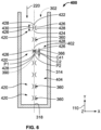
- the first point P1 of each of the first apertures 320 is collinear with the second point P2 of the respective one of the second apertures 360 along a line 390.
- Each line 390 is substantially parallel to the first centerline C1 of the respective one of the first apertures 320, and is substantially parallel to the second centerline C2 of the respective one of the second apertures 360.
- the fine sand and dust particles are aligned to pass through the second apertures 360, which reduces the accumulation of the particles or particulates (fine sand and dust) within the impingement tube 210.
- a lensing affect is created as the flow through the first apertures 320 is not concentrated along the centerline C1, but rather, is concentrated along the first downstream surface portion 324, as shown in FIG. 5 .
- the larger first dimension 326 of the first apertures 320 acts to accelerate and align particles, such as fine sand and dust, which directs the particles out of the impingement tube 210, thereby reducing a plugging of the impingement tube 210 or an accumulation of the particles within the impingement tube 210.
- the acceleration of the cooling fluid 220 by the first apertures 320 increases a velocity of the cooling fluid 220, which further reduces the accumulation of fine sand and dust particles within the impingement tube 210.
- each of the first apertures 320 is the same. It should be noted that in other examples, each of the first apertures 320 may have a different geometry or dimension. In addition, in certain embodiments, one or more of the first apertures 320 may have flow directing channels to reduce a stagnation region defined proximate the first upstream surface portion 322. In this regard, with reference to FIGS. 5A and 5B , each of the first apertures 320 may include a respective flow guide 378 and/or the interior surface 330 of the first tube body 300 may define a respective projection 380. Each of the flow guides 378 extend into each of the first apertures 320 ( FIG.
- the projections 380 extend outwardly from the interior surface 330 proximate the first downstream surface portion 324 of the respective first aperture 320 and project above the first downstream surface portion 324 to inhibit buildup at a stagnation point defined proximate the first downstream surface portion 324.
- the projections 380 also help funnel or guide the cooling flow into the respective first apertures 320 with minimal particulate accumulation on the interior surface 330 of the first tube body 300 proximate the first upstream surface portion 322 and first downstream surface portion 324.
- first apertures 320 and the second apertures 360 are described in FIGS. 1-5 as having the same geometry, in other embodiments, the first apertures 320 may have a different geometry than the second apertures 360 to direct the cooling fluid onto the surface 222 ( FIG. 1 ).
- a first wall 404 of a first tube body 402 associated with an impingement tube 400 is shown.
- the impingement tube 400 includes components that are substantially similar to or the same as the impingement tube 210 discussed with regard to FIGS. 1-5B , the same reference numerals will be used to denote the same or similar features.
- the first wall 404 defines a plurality of first apertures 420.
- the first wall 404 defines seven first apertures 420 that are spaced apart along the first wall 404, however, the first wall 404 may define any number of first apertures 420 from about one to about 30.
- Each of the first apertures 420 has a first upstream surface portion 422 opposite a first downstream surface portion 424 in the flow direction of the cooling fluid 220 into the impingement tube 400.
- each of the first apertures 420 has a second geometry, which includes a pair of concave surfaces 426 and a pair of convex surfaces 428.
- the concave surfaces 426 are opposite each other, and interconnected by a respective one of the convex surfaces 428.
- each of the first apertures 420 has a first geometry that is different than the second geometry of each of the second apertures 360.
- Each of the first apertures 420 also has a first dimension 430 defined between the first upstream surface portion 422 and the first downstream surface portion 424.
- the first dimension 430 is a distance, which is the same as the first dimension 326.
- Each of the first apertures 420 also has a first centerline C41.
- the first centerline C41 is substantially parallel to the axial direction.
- the first centerline C41 is offset from or non-collinear with the second centerline C2.
- the first downstream surface portion 424 of at least one of the first apertures 420 also includes the first point P1.
- Each of the first apertures 420 cooperate with a respective one of the second apertures 360 to direct the cooling fluid onto the surface 222 ( FIG. 2 ).
- the first point P1 of each of the first apertures 420 is collinear with the second point P2 of the respective one of the second apertures 360 along the line 390.
- Each line 390 is substantially parallel to the first centerline C41 of the respective one of the first apertures 420, and is substantially parallel to the second centerline C2 of the respective one of the second apertures 360.
- the shape of the first apertures 420 reduces a stagnation region associated with the circular first apertures 320.
- the concave surfaces 426 also assist in accelerating the flow through the first apertures 420 and in directing the flow through the respective second apertures 360 with minimal particulate accumulation on the surfaces of the apertures 420, 360.
- first apertures 320 and the second apertures 360 are described in FIGS. 1-5 as having the same geometry, in other embodiments, the first apertures 320 may have a different geometry than the second apertures 360 to direct the cooling fluid onto the surface 222 ( FIG. 1 ).
- a first wall 504 of a first tube body 502 associated with an impingement tube 500 is shown.
- the impingement tube 500 includes components that are substantially similar to or the same as the impingement tube 210 discussed with regard to FIGS. 1-5B , the same reference numerals will be used to denote the same or similar features.
- the first wall 504 defines a plurality of first apertures 520.
- the first wall 504 defines seven first apertures 520 that are spaced apart along the first wall 504, however, the first wall 504 may define any number of first apertures 520 from about one to about 30.
- Each of the first apertures 520 has a first upstream surface portion 522 opposite a first downstream surface portion 524 in the flow direction of the cooling fluid 220 into the impingement tube 500.
- each of the first apertures 520 has a second geometry, which includes a first concave surface 526, a first convex surface 528, a first arcuate surface 530, a second convex surface 532, a second arcuate surface 534 and a third convex surface 536.
- the first concave surface 526 is defined along the first upstream surface portion 522.
- the first concave surface 526 is interconnected with the first convex surface 528 and the third convex surface 536.
- the first convex surface 528 is defined along the first upstream surface portion 522.
- the first convex surface 528 interconnects the first concave surface 526 and the first arcuate surface 530.
- the first arcuate surface 530 defines a sidewall of each of the first apertures 520, and interconnects the first upstream surface portion 522 with the first downstream surface portion 524.
- the first arcuate surface 530 interconnects the first convex surface 528 and the second convex surface 532.
- the second convex surface 532 is defined along the first downstream surface portion 524.
- the second arcuate surface 534 defines another sidewall of each of the first apertures 520, and interconnects the first downstream surface portion 524 with the first upstream surface portion 522.
- the second arcuate surface 534 interconnects the second convex surface 532 and the third convex surface 536.
- the first arcuate surface 530 and the second arcuate surface 534 are opposite and form opposing sidewalls of each of the first apertures 520.
- the third convex surface 536 interconnects the second arcuate surface 534 and the first concave surface 526.
- the third convex surface 536 is defined along the first upstream surface portion 522.
- each of the first apertures 520 has a first geometry that is different than the second geometry of each of the second apertures 360.
- Each of the first apertures 520 also has a first dimension 540 defined between the first concave surface 526 of the first upstream surface portion 522 and the second convex surface 532 of the first downstream surface portion 524.
- the first dimension 540 is a distance, which is the same as the first dimension 326.
- Each of the first apertures 520 also has a first centerline C51.
- the first centerline C51 is substantially parallel to the axial direction.
- the first centerline C51 is offset from or non-collinear with the second centerline C2.
- the first downstream surface portion 524 of at least one of the first apertures 520 also includes the first point P1.
- Each of the first apertures 520 cooperate with a respective one of the second apertures 360 to direct the cooling fluid onto the surface 222 ( FIG. 2 ).
- the first point P1 of each of the first apertures 520 is collinear with the second point P2 of the respective one of the second apertures 360 along the line 390.
- Each line 390 is substantially parallel to the first centerline C51 of the respective one of the first apertures 520, and is substantially parallel to the second centerline C2 of the respective one of the second apertures 360.
- the shape of the first apertures 520 reduces a stagnation region associated with the circular first apertures 320 and the convex surfaces 528, 532, 536 assist in accelerating the flow through the first apertures 520 and into the respective second apertures 360.
- the result is that the combination of convex and concave surfaces in the first apertures 520 assist in accelerating the flow through the first apertures 520 and in directing the flow through the respective second apertures 360 with minimal particulate accumulation on the surfaces of the apertures 520, 360.
- first apertures 320 and the second apertures 360 are described in FIGS. 1-5 as having the same geometry, in other embodiments, the first apertures 320 may have a different geometry than the second apertures 360 to direct the cooling fluid onto the surface 222 ( FIG. 1 ).
- a first wall 604 of a first tube body 602 associated with an impingement tube 600 is shown.
- the impingement tube 600 includes components that are substantially similar to or the same as the impingement tube 210 discussed with regard to FIGS. 1-5B , the same reference numerals will be used to denote the same or similar features.
- the first wall 604 defines a plurality of first apertures 620.
- the first wall 604 defines seven first apertures 620 that are spaced apart along the first wall 604, however, the first wall 604 may define any number of first apertures 620 from about one to about 30.
- Each of the first apertures 620 has a first upstream surface portion 622 opposite a first downstream surface portion 624 in the flow direction of the cooling fluid 220 into the impingement tube 600.
- each of the first apertures 620 has a second geometry, which includes a first concave surface 626, a first convex surface 628, a second concave surface 630, a second convex surface 632, a third concave surface 634 and a third convex surface 636.
- the first concave surface 626 is defined along the first upstream surface portion 622.
- the first concave surface 626 is interconnected with the first convex surface 628 and the third convex surface 636.
- the first convex surface 628 is defined along the first upstream surface portion 622.
- the first convex surface 628 interconnects the first concave surface 626 and the second concave surface 630.
- the second concave surface 630 defines a sidewall of each of the first apertures 620, and interconnects the first upstream surface portion 622 with the first downstream surface portion 624.
- the second concave surface 630 interconnects the first convex surface 628 and the second convex surface 632.
- the second convex surface 632 is defined along the first downstream surface portion 624.
- the third concave surface 634 defines another sidewall of each of the first apertures 620, and interconnects the first downstream surface portion 624 with the first upstream surface portion 622.
- the second concave surface 630 and the third concave surface 634 are opposite and form opposing sidewalls of each of the first apertures 620.
- each of the first apertures 620 has a first geometry that is different than the second geometry of each of the second apertures 360.
- Each of the first apertures 620 also has a first dimension 640 defined between the first concave surface 626 of the first upstream surface portion 622 and the second convex surface 632 of the first downstream surface portion 624.
- the first dimension 640 is a distance, which is the same as the first dimension 326.
- Each of the first apertures 620 also has a first centerline C61.
- the first centerline C61 is substantially parallel to the axial direction.
- the first centerline C61 is offset from or non-collinear with the second centerline C2.
- the first downstream surface portion 624 of at least one of the first apertures 620 also includes the first point P1.
- Each of the first apertures 620 cooperate with a respective one of the second apertures 360 to direct the cooling fluid onto the surface 222 ( FIG. 2 ).
- the first point P1 of each of the first apertures 620 is collinear with the second point P2 of the respective one of the second apertures 360 along the line 390.
- Each line 390 is substantially parallel to the first centerline C61 of the respective one of the first apertures 620, and is substantially parallel to the second centerline C2 of the respective one of the second apertures 360.
- the shape of the first apertures 620 reduces a stagnation region associated with the circular first apertures 320 and the concave surfaces 630, 634 assist in accelerating the flow through the first apertures 620 and into the respective second apertures 360.
- the result is that the combination of convex and concave surfaces in the first apertures 620 assist in accelerating the flow through the first apertures 620 and in directing the flow through the respective second apertures 360 with minimal particulate accumulation on the surfaces of the apertures 620, 360.
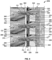
- first apertures 320, 420, 520, 620 have been illustrated herein as having the same hole shape defined along the respective first wall 314, 404, 504, 604, in other embodiments, a first wall may include a variety of hole shapes, such as a combination of one or more of the first apertures 320, 420, 520, 620.
- first apertures 320, 420, 520, 620 and the second apertures 360 have been described and illustrated herein as having the same first dimension 326, 430, 540, 640, in other embodiments, one or more of the first apertures 320, 420, 520, 620 and the second apertures 360 may have a different dimension along the respective wall 314, 404, 504, 604, 354 such that on the respective wall 314, 404, 504, 604, 354 one or more of the first apertures 320, 420, 520, 620 and the second apertures 360 may be larger or smaller than another one of the first apertures 320, 420, 520, 620 and the second apertures 360.
- first apertures 320, 420, 520, 620 and the second apertures 360 are substantially evenly spaced along the respective wall 314, 404, 504, 604, 354, in other embodiments, the first apertures 320, 420, 520, 620 and/or the second apertures 360 may be unevenly spaced.
- the impingement tube 210, 400, 500, 600 is formed with the respective first apertures 320, 420, 520, 620 and the second apertures 360, via additive manufacturing, for example.
- the impingement tube 210, 400, 500, 600 is coupled to the internal chamber 212 such that the second wall 354 is positioned adjacent to or proximate the surface 222.
- the turbine vane airfoil 202 is coupled to the outer annular endwall 204 and the inner annular endwall 206. This process is repeated for the remaining turbine vane airfoils 202 associated with the turbine nozzle 200.
- the turbine nozzle 200 is coupled to the gas turbine engine 100.
- the hot combustive gases 116 from the combustor 102 flow through the core gas flow path 112 defined in part by the airfoils 208 of the turbine nozzle 200.
- the cooling fluid 220 flows from the secondary source into the tube plenum 315 defined by the first tube body 300 of the impingement tube 210, 400, 500, 600.
- the cooling fluid 220 which may include fine sand and dust particles, flows through the first apertures 320, 420, 520, 620.
- the shape of the first apertures 420, 520, 620 further accelerates the cooling fluid 220 as it flows through the first apertures 420, 520, 620.
- the cooling fluid 220 exits the first apertures 320, 420, 520, 620 and flows through the second apertures 360.
- the second apertures 360 direct the cooling fluid 220 as impingement jets onto the surface 222, thereby cooling the surface 222.
- the cooling fluid 220 flows within the interior 228 of the airfoil 208 to the trailing outlet 230.
- the accumulation of fine sand and dust particles within the impingement tube 210, 400, 500, 600 is reduced, which ensures that the first apertures 320, 420, 520, 620 and the second apertures 360 remain clear or unclogged, thereby improving the cooling function of the impingement tube 210, 400, 500, 600.
- the life of the turbine vane airfoil 202 and thus, the turbine nozzle 200 is improved, which reduces a downtime associated with the maintenance and/or repair of the gas turbine engine 100.
Landscapes
- Engineering & Computer Science (AREA)
- Mechanical Engineering (AREA)
- General Engineering & Computer Science (AREA)
- Physics & Mathematics (AREA)
- Fluid Mechanics (AREA)
- Turbine Rotor Nozzle Sealing (AREA)
Abstract
Description
- The present disclosure generally relates to gas turbine engines, and more particularly relates to a turbine nozzle associated with a turbine of a gas turbine engine having a turbine vane airfoil with dust tolerant impingement cooling.
- Gas turbine engines may be employed to power various devices. For example, a gas turbine engine may be employed to power a mobile platform, such as an aircraft. In certain operating environments, such as desert operating environments, the gas turbine engine may ingest fine sand and dust particles during operation. These ingested fine sand and dust particles may pass through portions of the gas turbine engine and may accumulate in stagnation regions of cooling circuits within turbine components, such as the airfoils of a turbine vane associated with a turbine nozzle. The accumulation of the fine sand and dust particles in the stagnation regions of the cooling circuits in the turbine components, such as the airfoil, may impede the cooling of the airfoil, which in turn, may reduce the life of the airfoil and the turbine nozzle leading to increased repair costs and downtime for the gas turbine engine.
- Accordingly, it is desirable to provide a turbine nozzle with dust tolerant impingement cooling, which reduces the accumulation of fine sand and dust particles within turbine vane airfoils associated with the turbine nozzle, thereby increasing cooling of the turbine vane airfoils and the life of the turbine nozzle. Furthermore, other desirable features and characteristics of the present invention will become apparent from the subsequent detailed description and the appended claims, taken in conjunction with the accompanying drawings and the foregoing technical field and background.
- According to various embodiments, provided is a turbine vane airfoil for a turbine nozzle. The turbine vane airfoil includes an airfoil defining a chamber proximate a surface, and an impingement tube configured to be disposed in the chamber and configured to receive a cooling fluid. The impingement tube includes a first wall that is spaced apart from a second wall. The first wall defines a plurality of first apertures, and each of the plurality of first apertures has a first upstream surface portion opposite a first downstream surface portion in a flow direction of the cooling fluid into the impingement tube. The second wall defines a plurality of second apertures, and each of the plurality of second apertures has a second upstream surface portion opposite a second downstream surface portion. At least one of the plurality of first apertures has a first dimension between the first upstream surface portion and the first downstream surface portion that is greater than a second dimension between the second upstream surface portion and the second downstream surface portion of at least one of the plurality of second apertures. Each of the plurality of first apertures cooperate with a respective one of the plurality of second apertures to direct the cooling fluid onto the surface, and the first downstream surface portion of at least one of the plurality of first apertures includes a first point that is collinear with a second point of the second downstream surface portion of the respective one of the plurality of second apertures along a line, and the line is substantially parallel to a first centerline of the at least one of the plurality of first apertures.
- The at least one of the plurality of second apertures includes a second centerline, the first centerline is offset from the second centerline and the first centerline is substantially parallel to the second centerline. Each of the plurality of first apertures has a first geometry that is the same as a second geometry of each of the plurality of second apertures. Each of the plurality of first apertures has a first geometry that is different than a second geometry of each of the plurality of second apertures. At least one of the plurality of first apertures includes at least one convex surface. The at least one convex surface is defined at the first upstream surface portion. The at least one convex surface is defined at the first downstream surface portion. The at least one convex surface includes a pair of convex surfaces, with a first one of the pair of convex surfaces defined at the first upstream surface portion and a second one of the pair of convex surfaces defined at the first downstream surface portion. At least one of the plurality of first apertures includes at least one concave surface. The at least one concave surface is defined at the first upstream surface portion. At least one of the plurality of first apertures further comprises a pair of opposing sidewalls defined by a pair of arcuate surfaces. At least one of the plurality of first apertures further comprises a pair of opposing sidewalls defined by a pair of concave surfaces. The first upstream surface portion is defined by at least a concave surface and a convex surface. The first wall is an inner wall of the impingement tube, the second wall is an outer wall of the impingement tube, and the second wall is positioned between the first wall and the surface. The surface is opposite a leading edge of the airfoil. The impingement tube includes a first tube body that includes the first wall, a second tube body that includes the second wall, the first tube body defines a plenum configured to receive the cooling fluid into the impingement tube, and the first tube body is coupled to the second tube body such that a tube chamber is defined between at least a portion of the first tube body and the second tube body.
- Further provided is a turbine nozzle. The turbine nozzle includes a turbine vane airfoil including an airfoil defining a chamber proximate a surface, and an impingement tube configured to be disposed in the chamber. The impingement tube includes a first tube body including a first wall and a second tube body including a second wall. The first tube body defines a plenum configured to receive a cooling fluid. The first wall is spaced apart from the second wall, and the first wall defines a plurality of first apertures. Each of the plurality of first apertures has a first upstream surface portion opposite a first downstream surface portion in a flow direction of the cooling fluid into the first tube body. The second wall defines a plurality of second apertures, and each of the plurality of second apertures has a second upstream surface portion opposite a second downstream surface portion. At least one of the plurality of first apertures has a first dimension between the first upstream surface portion and the first downstream surface portion that is greater than a second dimension between the second upstream surface portion and the second downstream surface portion of at least one of the plurality of second apertures. Each of the plurality of first apertures cooperate with a respective one of the plurality of second apertures to direct the cooling fluid onto the surface. The first downstream surface portion of at least one of the plurality of first apertures includes a first point that is collinear with a second point of the second downstream surface portion of the respective one of the plurality of second apertures along a line and the line is substantially parallel to a first centerline of the at least one of the plurality of first apertures.
- The at least one of the plurality of second apertures includes a second centerline, the first centerline is offset from the second centerline and the first centerline is substantially parallel to the second centerline. Each of the plurality of first apertures has a first geometry that is different than a second geometry of each of the plurality of second apertures. The first wall is an inner wall of the impingement tube, the second wall is an outer wall of the impingement tube, the second wall is positioned between the first wall and the surface, and the surface is opposite a leading edge of the airfoil.
- The exemplary embodiments will hereinafter be described in conjunction with the following drawing figures, wherein like numerals denote like elements, and wherein:
-
FIG. 1 is a schematic cross-sectional illustration of a gas turbine engine, which includes an exemplary high pressure turbine nozzle with dust tolerant impingement cooling in accordance with the various teachings of the present disclosure; -
FIG. 1A is a schematic cross-sectional illustration of a portion of a turbine section of the gas turbine engine, taken at 1A ofFIG. 1 , which includes the exemplary high pressure turbine nozzle with a turbine vane airfoil having dust tolerant impingement cooling in accordance with the various teachings of the present disclosure; -
FIG. 2 is a cross-sectional view of the turbine vane airfoil ofFIG. 1A , taken at line 2-2 ofFIG. 1A , which illustrates an impingement tube associated with the turbine vane airfoil that provides dust tolerant impingement cooling for the turbine vane airfoil, and thus, the turbine nozzle; -
FIG. 2A is a front perspective view of the turbine vane airfoil including the impingement tube; -
FIG. 2B is a cross-sectional view, taken alongline 2B-2B ofFIG. 1A , which illustrates the turbine vane airfoil including the impingement tube; -
FIG. 3 is a detail cross-sectional view of the impingement tube ofFIG. 2 taken at 3 onFIG. 2 ; -
FIG. 4 is a cross-sectional view of the impingement tube ofFIG. 3 , taken at line 4-4 ofFIG. 3 , which illustrates an exemplary arrangement of a plurality of first apertures and a plurality of second apertures; -
FIG. 5 is a detail environmental cross-sectional view of the impingement tube ofFIG. 3 taken at 5 onFIG. 3 , which illustrates a flow of a cooling fluid through the plurality of first apertures and the plurality of second apertures; -
FIG. 5A is a detail environmental cross-sectional view of the impingement tube ofFIG. 3 taken from the perspective of 5 onFIG. 3 , which illustrates the flow of a cooling fluid through the plurality of first apertures and the plurality of second apertures in an example where each of the plurality of first apertures include a flow guide and a projection; -
FIG. 5B is a cross-sectional view of the impingement tube ofFIG. 3 , taken from the perspective of line 4-4 ofFIG. 3 , which illustrates the plurality of first apertures and the plurality of second apertures in the example where each of the plurality of first apertures include the flow guide and the projection; -
FIG. 6 is a cross-sectional view of another exemplary impingement tube, taken from the perspective of line 4-4 ofFIG. 3 , which illustrates another exemplary arrangement of a plurality of first apertures and the plurality of second apertures; -
FIG. 7 is a cross-sectional view of another exemplary impingement tube, taken from the perspective of line 4-4 ofFIG. 3 , which illustrates another exemplary arrangement of a plurality of first apertures and the plurality of second apertures; and -
FIG. 8 is a cross-sectional view of another exemplary impingement tube, taken from the perspective of line 4-4 ofFIG. 3 , which illustrates another exemplary arrangement of a plurality of first apertures and the plurality of second apertures. - The following detailed description is merely exemplary in nature and is not intended to limit the application and uses. Furthermore, there is no intention to be bound by any expressed or implied theory presented in the preceding technical field, background, brief summary or the following detailed description. In addition, those skilled in the art will appreciate that embodiments of the present disclosure may be practiced in conjunction with any type of component for a gas turbine engine that would benefit from dust tolerant impingement cooling and that the turbine vane airfoils associated with the turbine nozzle are merely one exemplary embodiment according to the present disclosure. Moreover, while the turbine nozzle is described herein as being used with a gas turbine engine onboard a mobile platform, such as a bus, motorcycle, train, motor vehicle, marine vessel, aircraft, rotorcraft and the like, the various teachings of the present disclosure can be used with a gas turbine engine on a stationary platform. Further, it should be noted that many alternative or additional functional relationships or physical connections may be present in an embodiment of the present disclosure. In addition, while the figures shown herein depict an example with certain arrangements of elements, additional intervening elements, devices, features, or components may be present in an actual embodiment. It should also be understood that the drawings are merely illustrative and may not be drawn to scale.
- As used herein, the term "axial" refers to a direction that is generally parallel to or coincident with an axis of rotation, axis of symmetry, or centerline of a component or components. For example, in a cylinder or disc with a centerline and generally circular ends or opposing faces, the "axial" direction may refer to the direction that generally extends in parallel to the centerline between the opposite ends or faces. In certain instances, the term "axial" may be utilized with respect to components that are not cylindrical (or otherwise radially symmetric). For example, the "axial" direction for a rectangular housing containing a rotating shaft may be viewed as a direction that is generally parallel to or coincident with the rotational axis of the shaft. Furthermore, the term "radially" as used herein may refer to a direction or a relationship of components with respect to a line extending outward from a shared centerline, axis, or similar reference, for example in a plane of a cylinder or disc that is perpendicular to the centerline or axis. In certain instances, components may be viewed as "radially" aligned even though one or both of the components may not be cylindrical (or otherwise radially symmetric). Furthermore, the terms "axial" and "radial" (and any derivatives) may encompass directional relationships that are other than precisely aligned with (e.g., oblique to) the true axial and radial dimensions, provided the relationship is predominately in the respective nominal axial or radial direction. As used herein, the term "substantially" denotes within 10% to account for manufacturing tolerances.
- With reference to
FIG. 1 , a partial, cross-sectional view of an exemplarygas turbine engine 100 is shown with the remaining portion of thegas turbine engine 100 being axisymmetric about alongitudinal axis 140, which also comprises an axis of rotation for thegas turbine engine 100. As will be discussed herein, thegas turbine engine 100 includes a turbine nozzle 200 (FIG. 1A ), which has at least one turbine vane system orturbine vane airfoil 202 with dust tolerant impingement cooling. By providing theturbine vane airfoil 202 with dust tolerant impingement cooling, the accumulation of fine sand and dust particles within theturbine vane airfoil 202 is reduced, which improves a life of theturbine nozzle 200. It should be noted that while theturbine nozzle 200 and theturbine vane airfoil 202 are illustrated and described herein as being used with thegas turbine engine 100, which can be included with an auxiliary power unit, theturbine nozzle 200 and/or theturbine vane airfoil 202 can be employed with various types of engines, including, but not limited to, turbofan, turboprop, turboshaft, and turbojet engines, whether deployed onboard an aircraft, watercraft, or ground vehicle (e.g., a tank), included within industrial power generators, or utilized within another platform or application. In this example, thegas turbine engine 100 is employed within anaircraft 99. - In the example shown in
FIG. 1 , thegas turbine engine 100 includes afan section 12, acompressor section 14, acombustor section 16, aturbine section 18, and anexhaust section 10. Thefan section 12 includes afan 22 mounted on arotor 24 that draws air into thegas turbine engine 100 and accelerates it. A fraction of the accelerated air exhausted from thefan 22 is directed through an outer (or first)bypass duct 26 and the remaining fraction of air exhausted from thefan 22 is directed into thecompressor section 14. Theouter bypass duct 26 is generally defined by aninner casing 28 and anouter casing 30. In the embodiment ofFIG. 1 , thecompressor section 14 includes anintermediate pressure compressor 32 and ahigh pressure compressor 34. However, in other embodiments, the number of compressors in thecompressor section 14 may vary. In the depicted embodiment, theintermediate pressure compressor 32 and thehigh pressure compressor 34 sequentially raise the pressure of the air and direct a majority of the high pressure air into thecombustor section 16. A fraction of the compressed air bypasses thecombustor section 16 and is used to cool, among other components, turbine blades in theturbine section 18. - In the
combustor section 16, which includes acombustor 102, the high pressure air is mixed with fuel, which is combusted. The high-temperature combustion air is directed into theturbine section 18. In this example, theturbine section 18 includes three turbines disposed in axial flow series, namely, ahigh pressure turbine 104, anintermediate pressure turbine 40, and alow pressure turbine 42. However, it will be appreciated that the number of turbines, and/or the configurations thereof, may vary. In this embodiment, the high-temperature air from thecombustor section 16 is directed through theturbine nozzle 200 and expands through and rotates eachturbine turbines gas turbine engine 100 via concentrically disposed shafts or spools. In one example, thehigh pressure turbine 104 drives thehigh pressure compressor 34 via ahigh pressure shaft 44, theintermediate pressure turbine 40 drives theintermediate pressure compressor 32 via anintermediate pressure shaft 46, and thelow pressure turbine 42 drives thefan 22 via alow pressure shaft 48. - With reference to
FIG. 1A , a portion of theturbine section 18 is shown in greater detail. In this example, thegas turbine engine 100 includes theturbine nozzle 200, as illustrated in accordance with an exemplary embodiment. In this example, theturbine nozzle 200 is a high pressure turbine nozzle. In addition to theturbine nozzle 200, the illustrated portion of thegas turbine engine 100 further includes a downstream or outlet end of thecombustor 102, thehigh pressure turbine 104, a surroundingturbine case 106, and aturbine shroud 108. Theturbine nozzle 200, the outlet end of thecombustor 102, thehigh pressure turbine 104, theturbine case 106 and theturbine shroud 108 are each generally axisymmetric about the centerline or rotational axis of thegas turbine engine 100, which is parallel to the X-axis identified by the coordinatelegend 110. A coregas flow path 112 extends through the illustrated portions of thegas turbine engine 100 and is defined by thecombustor 102, theturbine nozzle 200, thehigh pressure turbine 104, and theturbine shroud 108. During operation of thegas turbine engine 100, combustive gasses are discharged from thecombustor 102 and progress along the coregas flow path 112. Theturbine nozzle 200 is positioned immediately downstream of thecombustor 102 and upstream of thehigh pressure turbine 104. Theturbine nozzle 200 receives the hot, combustive gas flow discharged by thecombustor 102. Theturbine nozzle 200 meters, accelerates, and turns the combustive gas flow toward a plurality ofturbine blades 114 associated with thehigh pressure turbine 104. After exiting theturbine nozzle 200, the combustive gas flow drives rotation of thehigh pressure turbine 104 and non-illustrated shaft or shafts associated with thegas turbine engine 100. This, in turn, drives the rotation of other non-illustrated components (e.g., a fan or compressor rotor) associated with thegas turbine engine 100 and provides power output, which may be extracted from thegas turbine engine 100 in different forms. - The
turbine nozzle 200 includes an outerannular endwall 204 and an innerannular endwall 206, which are substantially concentric and radially spaced. The outer and innerannular endwalls gas flow path 112, which extends through theturbine nozzle 200. Theturbine nozzle 200 also includes a number of theturbine vane airfoils 202, one of which can be seen in the cross-section ofFIG. 1A . Theturbine vane airfoils 202 are arranged in an annular array, which is located between theannular endwalls turbine vane airfoils 202 extends between theannular endwalls turbine nozzle 200 and the centerline or rotational axis of thegas turbine engine 100. Thus, theturbine vane airfoil 202 shown inFIG. 1A extends in a radial direction, which corresponds to the Y-axis of the coordinatelegend 110. The axial direction is a direction perpendicular to the radial direction and parallel to the centerline of theturbine nozzle 200, and the axial direction corresponds to the X-axis of the coordinatelegend 110. The Z-axis is perpendicular to the Y-axis and the X-axis. Theturbine vane airfoil 202 is shown in a flattened or meridional state in the cross-sectional schematic ofFIG. 1A . - As shown in phantom in
FIG. 1 , theturbine vane airfoil 202 includes anairfoil 208 and animpingement tube 210. As will be discussed, theimpingement tube 210 provides dust tolerant impingement cooling for theairfoil 208 of theturbine vane airfoil 202, and thus, theturbine nozzle 200. In this example, theairfoil 208 includes an internal chamber 212 (FIG. 2 ), and theimpingement tube 210 is inserted into theinternal chamber 212 of theairfoil 208. Similar or identical impingement tubes are likewise inserted into the othernon-illustrated airfoils 208 ofturbine vane airfoils 202 associated with theturbine nozzle 200, which may be similar or identical to the illustratedturbine vane airfoil 202. Thus, theturbine nozzle 200 containsmultiple impingement tubes 210, which are collectively arranged in an annular array that is substantially concentric with the centerline of theturbine nozzle 200. For simplicity, the following description will focus primarily on the illustratedturbine vane airfoil 202 shown inFIGS. 1A and2 , and the illustratedimpingement tube 210 shown inFIGS. 1A-8 ; however, the following description is equally applicable to the other non-illustrated impingement tubes and turbine vane airfoils included within theturbine nozzle 200. - Referring to
FIGS. 1A and2 , theimpingement tube 210 is used to cool theairfoil 208 of theturbine vane airfoil 202 during operation of thegas turbine engine 100. Theimpingement tube 210 supports enhanced convective heat removal targeted at aleading edge portion 214 of theairfoil 208, which is primarily impinged by the combustive gas flow discharged from combustor 102 (represented by arrows 216). During operation of thegas turbine engine 100, a secondary flow system directs relatively cool airflow or cooling fluid 220 into anoutboard portion 218 of theimpingement tube 210. Thus, generally, a flow direction of the coolingfluid 220 into theimpingement tube 210 is in the radial direction. The cooling fluid 220 flows through theimpingement tube 210 and exits theimpingement tube 210 to provide cooling to theleading edge portion 214 of the airfoil 208 (FIG. 2A ). With continued reference toFIG. 2A , when theimpingement tube 210 is positioned within theairfoil 208, theimpingement tube 210 directs cooling impingement jets against an interior surface orsurface 222 of theleading edge portion 214 of theairfoil 208. Thesurface 222 is opposite aleading edge 224 of theairfoil 208. An exemplary cooling impingement jet is represented byarrow 226 inFIG. 2 . - With reference to
FIG. 2B , after impingement against thesurface 222 of theleading edge portion 214 of theairfoil 208, the coolingfluid 220 is conducted along an interior 228 of theairfoil 208 and exits theairfoil 208 through a trailingoutlet 230, as further indicated inFIG. 2B byarrow 232. In various embodiments, the coolingfluid 220 may additionally exit via film holes 234. With reference toFIG. 2 , theinterior 228 of theairfoil 208 may includeflow directing structures 236, such as ribs, pins, etc. to assist in directing the cooling airflow to the trailingoutlet 230. The trailingoutlet 230 is defined at a trailingedge 238 of theairfoil 208. The trailingedge 238 is substantially opposite theleading edge 224 in a chordwise direction or the axial direction. Atip 240 of theairfoil 208 is coupled to the outerannular endwall 204, and aroot 242 of theairfoil 208 is coupled to the innerannular endwall 206. Thetip 240 is opposite theroot 242 in a spanwise direction or the radial direction. - Generally, the
impingement tube 210 may be shaped and dimensioned such that aperipheral clearance 250 is provided betweenimpingement tube 210, thesurface 222 and theinterior 228 of theairfoil 208. Theperipheral clearance 250 allows the cooling air to flow around theimpingement tube 210 and along theinterior 228 of theairfoil 208 for additional convective cooling (FIG. 2B ). Theimpingement tube 210 may be coupled to theinternal chamber 212 via a press fit, for example, however, theimpingement tube 210 may be coupled to theairfoil 208 in another manner, such as by bonding, welding or with fasteners. In certain embodiments, theimpingement tube 210 may include aperipheral flange 252 or other peripheral projections, such as one or more tabs, which extend fromoutboard portion 218 of theimpingement tube 210. When theimpingement tube 210 is coupled to and inserted into theairfoil 208, theperipheral flange 252 may seat against amating surface 256 defined by an exterior 204a of the outerannular endwall 204 to further couple theimpingement tube 210 to theairfoil 208. - With reference to
FIG. 3 , theimpingement tube 210 is shown in greater detail. In this example, theimpingement tube 210 is a double-wall impingement tube, and includes an inner,first tube body 300 and an outer,second tube body 302. In one example, theimpingement tube 210 is composed of metal or metal alloy, and is cast, formed, and machined, additively manufactured via direct metal laser sintering (DMLS), etc. In this example, thefirst tube body 300 and thesecond tube body 302 are integrally formed via additive manufacturing, including, but not limited to DMLS, but it should be noted that thefirst tube body 300 and thesecond tube body 302 may be formed discretely and coupled together via welding, adhesives, press-fit, mechanical fasteners, etc. In addition, it should be noted that while theimpingement tube 210 is shown and described herein as being discretely formed or separate from theairfoil 208, in other embodiments, theimpingement tube 210 may be integrally formed with, one-piece or monolithic with theairfoil 208. Thefirst tube body 300 is an inner tube of theimpingement tube 210, while thesecond tube body 302 is an outer tube of theimpingement tube 210. Thesecond tube body 302 is positioned between thefirst tube body 300 and the surface 222 (FIG. 2 ). - The
first tube body 300 includes afirst body end 310 opposite asecond body end 312 in the radial direction. A plurality offirst walls 314 couple or interconnect thefirst body end 310 with thesecond body end 312 to define a substantially elongated hollow tube. Thefirst body end 310 is at theoutboard portion 218 of theimpingement tube 210, and thesecond body end 312 is proximate aninboard end 258 of the airfoil 208 (FIG. 2 ). Thefirst body end 310 is open about its perimeter to enable the secondary cooling flow to enter into thefirst tube body 300 and flow to thesecond body end 312. Thus, thefirst body end 310 is an upstream end of thefirst tube body 300, and thesecond body end 312 is a downstream end of thefirst tube body 300 in a flow direction of the coolingfluid 220. In this example, thefirst body end 310 is integrally formed with thesecond tube body 302, while thesecond body end 312 is spaced apart from and uncoupled from thesecond tube body 302 to define atube chamber 316 between thefirst tube body 300 and thesecond tube body 302. In the event that one or more of thefirst apertures 320 of thefirst tube body 300 plug with particulates, such as fine sand and/or dust, thetube chamber 316 enables cooling flow to still supply some cooling air to the respectivesecond apertures 360 of thesecond tube body 302 to cool theinterior surface 222 of theleading edge 224. Thesecond body end 312 is closed at its perimeter or defines aplanar surface 318, which encloses or interconnects thefirst walls 314 at thesecond body end 312 and directs the cooling fluid toward thefirst walls 314. - The
first walls 314 extend about the perimeter of thefirst tube body 300 and enclose the perimeter of thefirst tube body 300 to define atube plenum 315. Thefirst walls 314 are each substantially planar or flat, but in certain examples, one or more of thefirst walls 314 may be curved or arcuate to correspond with a shape of theinternal chamber 212 of the airfoil 208 (FIG. 2B ). One or more of thefirst walls 314 defines a plurality offirst apertures 320. In this example, thefirst tube body 300 is illustrated with onefirst wall 314 defining thefirst apertures 320, but it should be understood that eachfirst wall 314 of thefirst tube body 300 may define thefirst apertures 320. In one example, thefirst wall 314 defines sevenfirst apertures 320 that are spaced apart along thefirst wall 314, however, thefirst wall 314 may define any number offirst apertures 320 from about one to about 30. Each of thefirst apertures 320 has a firstupstream surface portion 322 opposite a firstdownstream surface portion 324 in the flow direction of the coolingfluid 220 into theimpingement tube 210. - With reference to
FIG. 4 , each of thefirst apertures 320 has a first geometry, which is circular. Each of thefirst apertures 320 also has afirst dimension 326 defined between the firstupstream surface portion 322 and the firstdownstream surface portion 324. In this example, thefirst dimension 326 is a first diameter. Thefirst dimension 326 is about 0.020 inches (in.) to about 0.100 inches (in.), however, thefirst dimension 326 may vary based on a length of thefirst tube body 300 in the radial direction. With reference back toFIG. 3 , each of thefirst apertures 320 also has a first centerline C1. The first centerline C1 is substantially parallel to the axial direction. The firstdownstream surface portion 324 of at least one of thefirst apertures 320 also includes a first point P1. In this example, the first point P1 is defined at anexterior surface 328 of thefirst wall 314 that defines thefirst apertures 320. Theexterior surface 328 faces thesecond tube body 302. Theexterior surface 328 is opposite aninterior surface 330 of thefirst tube body 300. Theinterior surface 330 is disposed within thetube plenum 315. - The
second tube body 302 includes athird body end 350 opposite afourth body end 352 in the radial direction. A plurality ofsecond walls 354 couple or interconnect thethird body end 350 with thefourth body end 352 to define a substantially elongated hollow tube. Thethird body end 350 is at theoutboard portion 218 of theimpingement tube 210, and thefourth body end 352 is at theinboard end 258 of the airfoil 208 (FIG. 2 ). Thethird body end 350 interconnects thesecond tube body 302 to thefirst body end 310. Thethird body end 350 is closed such that the cooling fluid within thetube chamber 316 is inhibited from exiting through thethird body end 350. Thethird body end 350 is an upstream end of thesecond tube body 302, and thefourth body end 352 is a downstream end of thesecond tube body 302 in the flow direction of the coolingfluid 220 into theimpingement tube 210. Thefourth body end 352 is closed at is perimeter or defines aplanar surface 356, which encloses or interconnects thesecond walls 354 at thefourth body end 352. - The
second walls 354 extend about the perimeter of thesecond tube body 302 and enclose the perimeter of thesecond tube body 302 to surround thetube chamber 316. Thetube chamber 316 is defined between thefirst tube body 300 and thesecond tube body 302 so as to extend between thewalls second body end 312 and thefourth body end 352. Thus, thesecond walls 354 are spaced apart from thefirst walls 314. Thefirst walls 314 form an inner wall of theimpingement tube 210, while thesecond walls 354 form an outer wall of theimpingement tube 210. Thesecond walls 354 are each substantially planar or flat, but in certain examples, one or more of thesecond walls 354 may be curved or arcuate to correspond with a shape of theinternal chamber 212 of the airfoil 208 (FIG. 2 ). One or more of thesecond walls 354 defines a plurality ofsecond apertures 360. In this example, thesecond tube body 302 is illustrated with onesecond wall 354 defining thesecond apertures 360, but it should be understood that eachsecond wall 354 of thesecond tube body 302 may define thesecond apertures 360. Thesecond wall 354 is positioned between thefirst wall 314 and the surface 222 (FIG. 2 ). In one example, thesecond wall 354 defines sevensecond apertures 360 that are spaced apart along thesecond wall 354, however, thesecond wall 354 may define any number ofsecond apertures 360 from about one to about 30 that corresponds with the number offirst apertures 320. Each of thesecond apertures 360 has a secondupstream surface portion 362 opposite a seconddownstream surface portion 364 in the flow direction of the coolingfluid 220 into theimpingement tube 210. - With reference to
FIG. 4 , in this example, each of thesecond apertures 360 has a second geometry, which is circular. Each of thesecond apertures 360 also has asecond dimension 366 defined between the secondupstream surface portion 362 and the seconddownstream surface portion 364. In this example, thesecond dimension 366 is a second diameter. Thesecond dimension 366 is about 0.015 inches (in.) to about 0.075 inches (in.), however, thesecond dimension 366 may vary based on a length of thesecond tube body 302 in the radial direction. In this example, thefirst dimension 326 is different, and greater than, thesecond dimension 366. - With reference back to
FIG. 3 , each of thesecond apertures 360 also has a second centerline C2. The second centerline C2 is substantially parallel to the axial direction. The first centerline C1 is offset from or not collinear with the second centerline C2, but the second centerline C2 is substantially parallel to the first centerline C1. The seconddownstream surface portion 364 of at least one of thesecond apertures 360 also includes a second point P2. In this example, the second point P2 is defined at aninterior surface 368 of thesecond wall 354 that defines thesecond apertures 360. Theinterior surface 368 faces thefirst tube body 300, and is opposite anexterior surface 370 of thesecond tube body 302. Theexterior surface 370 faces thesurface 222 of the leading edge 224 (FIG. 2 ). - Each of the
first apertures 320 cooperate with a respective one of thesecond apertures 360 to direct the coolingfluid 220 onto the surface 222 (FIG. 2 ). With reference toFIG. 5 , a detail view of a portion of theimpingement tube 210 is shown. The first point P1 of each of thefirst apertures 320 is collinear with the second point P2 of the respective one of thesecond apertures 360 along aline 390. Eachline 390 is substantially parallel to the first centerline C1 of the respective one of thefirst apertures 320, and is substantially parallel to the second centerline C2 of the respective one of thesecond apertures 360. By aligning the points P1, P2 collinear along theline 390, the fine sand and dust particles are aligned to pass through thesecond apertures 360, which reduces the accumulation of the particles or particulates (fine sand and dust) within theimpingement tube 210. In addition, by aligning the points P1, P2 collinear along theline 390, a lensing affect is created as the flow through thefirst apertures 320 is not concentrated along the centerline C1, but rather, is concentrated along the firstdownstream surface portion 324, as shown inFIG. 5 . In addition, the largerfirst dimension 326 of thefirst apertures 320 acts to accelerate and align particles, such as fine sand and dust, which directs the particles out of theimpingement tube 210, thereby reducing a plugging of theimpingement tube 210 or an accumulation of the particles within theimpingement tube 210. In addition, the acceleration of the coolingfluid 220 by thefirst apertures 320 increases a velocity of the coolingfluid 220, which further reduces the accumulation of fine sand and dust particles within theimpingement tube 210. Larger fine sand and dust particles that cannot maintain alignment with the flow of the coolingfluid 220 through thefirst apertures 320 and thesecond apertures 360 bounce off thesurface 318 and are deflected through thefirst apertures 320 and thesecond apertures 360, which further reduces the accumulation within theimpingement tube 210. By aligning the points P1, P2 collinear along theline 390, particulates are less likely to stick on the entrance of thesecond apertures 360 at the secondupstream surface portion 362 or on the seconddownstream surface portion 364. Less accumulation of particulates results in more robust impingement cooling of theinterior surface 222. - In this example, each of the
first apertures 320 is the same. It should be noted that in other examples, each of thefirst apertures 320 may have a different geometry or dimension. In addition, in certain embodiments, one or more of thefirst apertures 320 may have flow directing channels to reduce a stagnation region defined proximate the firstupstream surface portion 322. In this regard, with reference toFIGS. 5A and5B , each of thefirst apertures 320 may include arespective flow guide 378 and/or theinterior surface 330 of thefirst tube body 300 may define arespective projection 380. Each of the flow guides 378 extend into each of the first apertures 320 (FIG. 5B ) and cooperate with the respectivefirst aperture 320 to taper each of thefirst apertures 320 from theinterior surface 330 to theexterior surface 328 of thefirst wall 314. The taper defined by the flow guides 378 substantially eliminates a stagnation region within the respectivefirst aperture 320, while also directing the flow into the respectivesecond aperture 360. Theprojections 380 extend outwardly from theinterior surface 330 proximate the firstdownstream surface portion 324 of the respectivefirst aperture 320 and project above the firstdownstream surface portion 324 to inhibit buildup at a stagnation point defined proximate the firstdownstream surface portion 324. Theprojections 380 also help funnel or guide the cooling flow into the respectivefirst apertures 320 with minimal particulate accumulation on theinterior surface 330 of thefirst tube body 300 proximate the firstupstream surface portion 322 and firstdownstream surface portion 324. - Further, while the
first apertures 320 and thesecond apertures 360 are described inFIGS. 1-5 as having the same geometry, in other embodiments, thefirst apertures 320 may have a different geometry than thesecond apertures 360 to direct the cooling fluid onto the surface 222 (FIG. 1 ). For example, with reference toFIG. 6 , afirst wall 404 of afirst tube body 402 associated with animpingement tube 400 is shown. As theimpingement tube 400 includes components that are substantially similar to or the same as theimpingement tube 210 discussed with regard toFIGS. 1-5B , the same reference numerals will be used to denote the same or similar features. Thefirst wall 404 defines a plurality offirst apertures 420. In one example, thefirst wall 404 defines sevenfirst apertures 420 that are spaced apart along thefirst wall 404, however, thefirst wall 404 may define any number offirst apertures 420 from about one to about 30. Each of thefirst apertures 420 has a firstupstream surface portion 422 opposite a firstdownstream surface portion 424 in the flow direction of the coolingfluid 220 into theimpingement tube 400. - In this example, each of the
first apertures 420 has a second geometry, which includes a pair ofconcave surfaces 426 and a pair ofconvex surfaces 428. Theconcave surfaces 426 are opposite each other, and interconnected by a respective one of the convex surfaces 428. Thus, in this example, each of thefirst apertures 420 has a first geometry that is different than the second geometry of each of thesecond apertures 360. Each of thefirst apertures 420 also has afirst dimension 430 defined between the firstupstream surface portion 422 and the firstdownstream surface portion 424. In this example, thefirst dimension 430 is a distance, which is the same as thefirst dimension 326. Each of thefirst apertures 420 also has a first centerline C41. The first centerline C41 is substantially parallel to the axial direction. The first centerline C41 is offset from or non-collinear with the second centerline C2. The firstdownstream surface portion 424 of at least one of thefirst apertures 420 also includes the first point P1. - Each of the
first apertures 420 cooperate with a respective one of thesecond apertures 360 to direct the cooling fluid onto the surface 222 (FIG. 2 ). The first point P1 of each of thefirst apertures 420 is collinear with the second point P2 of the respective one of thesecond apertures 360 along theline 390. Eachline 390 is substantially parallel to the first centerline C41 of the respective one of thefirst apertures 420, and is substantially parallel to the second centerline C2 of the respective one of thesecond apertures 360. By aligning the points P1, P2 collinear along theline 390, the fine sand and dust particles are aligned to pass through thesecond apertures 360, which reduces the accumulation of the particles (fine sand and dust) within theimpingement tube 400. By shaping thefirst apertures 420 to include theconcave surfaces 426, the shape of thefirst apertures 420 reduces a stagnation region associated with the circularfirst apertures 320. Theconcave surfaces 426 also assist in accelerating the flow through thefirst apertures 420 and in directing the flow through the respectivesecond apertures 360 with minimal particulate accumulation on the surfaces of theapertures - In addition, while the
first apertures 320 and thesecond apertures 360 are described inFIGS. 1-5 as having the same geometry, in other embodiments, thefirst apertures 320 may have a different geometry than thesecond apertures 360 to direct the cooling fluid onto the surface 222 (FIG. 1 ). For example, with reference toFIG. 7 , afirst wall 504 of afirst tube body 502 associated with animpingement tube 500 is shown. As theimpingement tube 500 includes components that are substantially similar to or the same as theimpingement tube 210 discussed with regard toFIGS. 1-5B , the same reference numerals will be used to denote the same or similar features. Thefirst wall 504 defines a plurality offirst apertures 520. In one example, thefirst wall 504 defines sevenfirst apertures 520 that are spaced apart along thefirst wall 504, however, thefirst wall 504 may define any number offirst apertures 520 from about one to about 30. Each of thefirst apertures 520 has a firstupstream surface portion 522 opposite a firstdownstream surface portion 524 in the flow direction of the coolingfluid 220 into theimpingement tube 500. - In this example, each of the
first apertures 520 has a second geometry, which includes a firstconcave surface 526, a firstconvex surface 528, a firstarcuate surface 530, a secondconvex surface 532, a secondarcuate surface 534 and a thirdconvex surface 536. The firstconcave surface 526 is defined along the firstupstream surface portion 522. The firstconcave surface 526 is interconnected with the firstconvex surface 528 and the thirdconvex surface 536. The firstconvex surface 528 is defined along the firstupstream surface portion 522. The firstconvex surface 528 interconnects the firstconcave surface 526 and the firstarcuate surface 530. The firstarcuate surface 530 defines a sidewall of each of thefirst apertures 520, and interconnects the firstupstream surface portion 522 with the firstdownstream surface portion 524. The firstarcuate surface 530 interconnects the firstconvex surface 528 and the secondconvex surface 532. The secondconvex surface 532 is defined along the firstdownstream surface portion 524. The secondarcuate surface 534 defines another sidewall of each of thefirst apertures 520, and interconnects the firstdownstream surface portion 524 with the firstupstream surface portion 522. The secondarcuate surface 534 interconnects the secondconvex surface 532 and the thirdconvex surface 536. The firstarcuate surface 530 and the secondarcuate surface 534 are opposite and form opposing sidewalls of each of thefirst apertures 520. The thirdconvex surface 536 interconnects the secondarcuate surface 534 and the firstconcave surface 526. The thirdconvex surface 536 is defined along the firstupstream surface portion 522. Thus, in this example, each of thefirst apertures 520 has a first geometry that is different than the second geometry of each of thesecond apertures 360. Each of thefirst apertures 520 also has afirst dimension 540 defined between the firstconcave surface 526 of the firstupstream surface portion 522 and the secondconvex surface 532 of the firstdownstream surface portion 524. In this example, thefirst dimension 540 is a distance, which is the same as thefirst dimension 326. Each of thefirst apertures 520 also has a first centerline C51. The first centerline C51 is substantially parallel to the axial direction. The first centerline C51 is offset from or non-collinear with the second centerline C2. The firstdownstream surface portion 524 of at least one of thefirst apertures 520 also includes the first point P1. - Each of the
first apertures 520 cooperate with a respective one of thesecond apertures 360 to direct the cooling fluid onto the surface 222 (FIG. 2 ). The first point P1 of each of thefirst apertures 520 is collinear with the second point P2 of the respective one of thesecond apertures 360 along theline 390. Eachline 390 is substantially parallel to the first centerline C51 of the respective one of thefirst apertures 520, and is substantially parallel to the second centerline C2 of the respective one of thesecond apertures 360. By aligning the points P1, P2 collinear along theline 390, the fine sand and dust particles are aligned to pass through thesecond apertures 360, which reduces the accumulation of the particles (fine sand and dust) within theimpingement tube 500. By shaping thefirst apertures 520 to include theconvex surfaces first apertures 520 reduces a stagnation region associated with the circularfirst apertures 320 and theconvex surfaces first apertures 520 and into the respectivesecond apertures 360. The result is that the combination of convex and concave surfaces in thefirst apertures 520 assist in accelerating the flow through thefirst apertures 520 and in directing the flow through the respectivesecond apertures 360 with minimal particulate accumulation on the surfaces of theapertures - While the
first apertures 320 and thesecond apertures 360 are described inFIGS. 1-5 as having the same geometry, in other embodiments, thefirst apertures 320 may have a different geometry than thesecond apertures 360 to direct the cooling fluid onto the surface 222 (FIG. 1 ). For example, with reference toFIG. 8 , afirst wall 604 of afirst tube body 602 associated with animpingement tube 600 is shown. As theimpingement tube 600 includes components that are substantially similar to or the same as theimpingement tube 210 discussed with regard toFIGS. 1-5B , the same reference numerals will be used to denote the same or similar features. Thefirst wall 604 defines a plurality offirst apertures 620. In one example, thefirst wall 604 defines sevenfirst apertures 620 that are spaced apart along thefirst wall 604, however, thefirst wall 604 may define any number offirst apertures 620 from about one to about 30. Each of thefirst apertures 620 has a firstupstream surface portion 622 opposite a firstdownstream surface portion 624 in the flow direction of the coolingfluid 220 into theimpingement tube 600. - In this example, each of the
first apertures 620 has a second geometry, which includes a firstconcave surface 626, a firstconvex surface 628, a secondconcave surface 630, a secondconvex surface 632, a thirdconcave surface 634 and a thirdconvex surface 636. The firstconcave surface 626 is defined along the firstupstream surface portion 622. The firstconcave surface 626 is interconnected with the firstconvex surface 628 and the thirdconvex surface 636. The firstconvex surface 628 is defined along the firstupstream surface portion 622. The firstconvex surface 628 interconnects the firstconcave surface 626 and the secondconcave surface 630. The secondconcave surface 630 defines a sidewall of each of thefirst apertures 620, and interconnects the firstupstream surface portion 622 with the firstdownstream surface portion 624. The secondconcave surface 630 interconnects the firstconvex surface 628 and the secondconvex surface 632. The secondconvex surface 632 is defined along the firstdownstream surface portion 624. The thirdconcave surface 634 defines another sidewall of each of thefirst apertures 620, and interconnects the firstdownstream surface portion 624 with the firstupstream surface portion 622. The secondconcave surface 630 and the thirdconcave surface 634 are opposite and form opposing sidewalls of each of thefirst apertures 620. The thirdconcave surface 634 interconnects the secondconvex surface 632 and the thirdconvex surface 636. The thirdconvex surface 636 interconnects the thirdconcave surface 634 and the firstconcave surface 626. The thirdconvex surface 636 is defined along the firstupstream surface portion 622. Thus, in this example, each of thefirst apertures 620 has a first geometry that is different than the second geometry of each of thesecond apertures 360. Each of thefirst apertures 620 also has afirst dimension 640 defined between the firstconcave surface 626 of the firstupstream surface portion 622 and the secondconvex surface 632 of the firstdownstream surface portion 624. In this example, thefirst dimension 640 is a distance, which is the same as thefirst dimension 326. Each of thefirst apertures 620 also has a first centerline C61. The first centerline C61 is substantially parallel to the axial direction. The first centerline C61 is offset from or non-collinear with the second centerline C2. The firstdownstream surface portion 624 of at least one of thefirst apertures 620 also includes the first point P1. - Each of the
first apertures 620 cooperate with a respective one of thesecond apertures 360 to direct the cooling fluid onto the surface 222 (FIG. 2 ). The first point P1 of each of thefirst apertures 620 is collinear with the second point P2 of the respective one of thesecond apertures 360 along theline 390. Eachline 390 is substantially parallel to the first centerline C61 of the respective one of thefirst apertures 620, and is substantially parallel to the second centerline C2 of the respective one of thesecond apertures 360. By aligning the points P1, P2 collinear along theline 390, the fine sand and dust particles are aligned to pass through thesecond apertures 360, which reduces the accumulation of the particles (fine sand and dust) within theimpingement tube 600. By shaping thefirst apertures 620 to include theconcave surfaces first apertures 620 reduces a stagnation region associated with the circularfirst apertures 320 and theconcave surfaces first apertures 620 and into the respectivesecond apertures 360. The result is that the combination of convex and concave surfaces in thefirst apertures 620 assist in accelerating the flow through thefirst apertures 620 and in directing the flow through the respectivesecond apertures 360 with minimal particulate accumulation on the surfaces of theapertures - In addition, it should be noted that while the
first apertures first wall first apertures first apertures second apertures 360 have been described and illustrated herein as having the samefirst dimension first apertures second apertures 360 may have a different dimension along therespective wall respective wall first apertures second apertures 360 may be larger or smaller than another one of thefirst apertures second apertures 360. In addition, while thefirst apertures second apertures 360 are substantially evenly spaced along therespective wall first apertures second apertures 360 may be unevenly spaced. - In one example, in order to assemble the
turbine nozzle 200, with reference toFIGS. 2-4 and6-8 , theimpingement tube first apertures second apertures 360, via additive manufacturing, for example. With theturbine vane airfoil 202 formed with theinternal chamber 212, theimpingement tube internal chamber 212 such that thesecond wall 354 is positioned adjacent to or proximate thesurface 222. Theturbine vane airfoil 202 is coupled to the outerannular endwall 204 and the innerannular endwall 206. This process is repeated for the remainingturbine vane airfoils 202 associated with theturbine nozzle 200. - With the
turbine nozzle 200 assembled, theturbine nozzle 200 is coupled to thegas turbine engine 100. During operation of thegas turbine engine 100, the hot combustive gases 116 from thecombustor 102 flow through the coregas flow path 112 defined in part by theairfoils 208 of theturbine nozzle 200. The cooling fluid 220 flows from the secondary source into thetube plenum 315 defined by thefirst tube body 300 of theimpingement tube fluid 220, which may include fine sand and dust particles, flows through thefirst apertures first apertures first apertures first apertures second apertures 360. Thesecond apertures 360 direct the cooling fluid 220 as impingement jets onto thesurface 222, thereby cooling thesurface 222. The cooling fluid 220 flows within theinterior 228 of theairfoil 208 to the trailingoutlet 230. - Due to the alignment of the first
downstream surface portion downstream surface portion 364 along theline 390, the accumulation of fine sand and dust particles within theimpingement tube first apertures second apertures 360 remain clear or unclogged, thereby improving the cooling function of theimpingement tube impingement tube turbine vane airfoil 202 and thus, theturbine nozzle 200, is improved, which reduces a downtime associated with the maintenance and/or repair of thegas turbine engine 100. - In this document, relational terms such as first and second, and the like may be used solely to distinguish one entity or action from another entity or action without necessarily requiring or implying any actual such relationship or order between such entities or actions. Numerical ordinals such as "first," "second," "third," etc. simply denote different singles of a plurality and do not imply any order or sequence unless specifically defined by the claim language. The sequence of the text in any of the claims does not imply that process steps must be performed in a temporal or logical order according to such sequence unless it is specifically defined by the language of the claim. The process steps may be interchanged in any order without departing from the scope of the invention as long as such an interchange does not contradict the claim language and is not logically nonsensical.
- While at least one exemplary embodiment has been presented in the foregoing detailed description, it should be appreciated that a vast number of variations exist. It should also be appreciated that the exemplary embodiment or exemplary embodiments are only examples, and are not intended to limit the scope, applicability, or configuration of the disclosure in any way. Rather, the foregoing detailed description will provide those skilled in the art with a convenient road map for implementing the exemplary embodiment or exemplary embodiments. It should be understood that various changes can be made in the function and arrangement of elements without departing from the scope of the disclosure as set forth in the appended claims and the legal equivalents thereof.
Claims (15)
- A turbine vane airfoil for a turbine nozzle, comprising:an airfoil defining a chamber proximate a surface; andan impingement tube configured to be disposed in the chamber and configured to receive a cooling fluid, the impingement tube including a first wall that is spaced apart from a second wall, the first wall defining a plurality of first apertures, each of the plurality of first apertures having a first upstream surface portion opposite a first downstream surface portion in a flow direction of the cooling fluid into the impingement tube, the second wall defining a plurality of second apertures, each of the plurality of second apertures having a second upstream surface portion opposite a second downstream surface portion, at least one of the plurality of first apertures having a first dimension between the first upstream surface portion and the first downstream surface portion that is greater than a second dimension between the second upstream surface portion and the second downstream surface portion of at least one of the plurality of second apertures, each of the plurality of first apertures cooperate with a respective one of the plurality of second apertures to direct the cooling fluid onto the surface, the first downstream surface portion of at least one of the plurality of first apertures includes a first point that is collinear with a second point of the second downstream surface portion of the respective one of the plurality of second apertures along a line and the line is substantially parallel to a first centerline of the at least one of the plurality of first apertures.
- The turbine vane airfoil of any one of the preceding claims, wherein the at least one of the plurality of second apertures includes a second centerline, the first centerline is offset from the second centerline and the first centerline is substantially parallel to the second centerline.
- The turbine vane airfoil of any one of Claims 1 or 2, wherein each of the plurality of first apertures has a first geometry that is the same as a second geometry of each of the plurality of second apertures.
- The turbine vane airfoil of any one of Claims 1 or 2, wherein each of the plurality of first apertures has a first geometry that is different than a second geometry of each of the plurality of second apertures.
- The turbine vane airfoil of Claim 4, wherein at least one of the plurality of first apertures includes at least one convex surface.
- The turbine vane airfoil of Claim 5, wherein the at least one convex surface is defined at the first upstream surface portion or the at least one convex surface is defined at the first downstream surface portion.
- The turbine vane airfoil of Claim 5, wherein the at least one convex surface includes a pair of convex surfaces, with a first one of the pair of convex surfaces defined at the first upstream surface portion and a second one of the pair of convex surfaces defined at the first downstream surface portion.
- The turbine vane airfoil of Claim 4, wherein at least one of the plurality of first apertures includes at least one concave surface.
- The turbine vane airfoil of Claim 8, wherein the at least one concave surface is defined at the first upstream surface portion.
- The turbine vane airfoil of Claim 4, wherein at least one of the plurality of first apertures further comprises a pair of opposing sidewalls defined by a pair of arcuate surfaces.
- The turbine vane airfoil of Claim 4, wherein at least one of the plurality of first apertures further comprises a pair of opposing sidewalls defined by a pair of concave surfaces.
- The turbine vane airfoil of any one of the preceding claims, wherein the first upstream surface portion is defined by at least a concave surface and a convex surface.
- The turbine vane airfoil of any one of the preceding claims, wherein the first wall is an inner wall of the impingement tube, the second wall is an outer wall of the impingement tube, the second wall is positioned between the first wall and the surface, and the surface is opposite a leading edge of the airfoil.
- The turbine vane airfoil of any one of the preceding claims, wherein the impingement tube further comprises a first tube body that includes the first wall, a second tube body that includes the second wall, the first tube body defines a plenum configured to receive the cooling fluid into the impingement tube, and the first tube body is coupled to the second tube body such that a tube chamber is defined between at least a portion of the first tube body and the second tube body.
- A turbine nozzle, comprising:
the turbine vane airfoil of Claim 1.
Applications Claiming Priority (1)
| Application Number | Priority Date | Filing Date | Title |
|---|---|---|---|
| US18/155,144 US11846203B1 (en) | 2023-01-17 | 2023-01-17 | Turbine nozzle with dust tolerant impingement cooling |
Publications (1)
| Publication Number | Publication Date |
|---|---|
| EP4403747A1 true EP4403747A1 (en) | 2024-07-24 |
Family
ID=89171012
Family Applications (1)
| Application Number | Title | Priority Date | Filing Date |
|---|---|---|---|
| EP23220212.7A Pending EP4403747A1 (en) | 2023-01-17 | 2023-12-26 | Turbine nozzle with dust tolerant impingement cooling |
Country Status (2)
| Country | Link |
|---|---|
| US (1) | US11846203B1 (en) |
| EP (1) | EP4403747A1 (en) |
Families Citing this family (1)
| Publication number | Priority date | Publication date | Assignee | Title |
|---|---|---|---|---|
| WO2025227348A1 (en) * | 2024-04-30 | 2025-11-06 | 臧宝华 | Heat exchange blade |
Citations (3)
| Publication number | Priority date | Publication date | Assignee | Title |
|---|---|---|---|---|
| US20180230836A1 (en) * | 2017-02-15 | 2018-08-16 | Rolls-Royce Plc | Stator vane section |
| EP3647544A1 (en) * | 2018-11-01 | 2020-05-06 | United Technologies Corporation | Cooled gas turbine guide vane airfoil |
| EP3656986A1 (en) * | 2018-11-23 | 2020-05-27 | United Technologies Corporation | Airfoil, corresponding baffle assembly and gas turbine engine |
Family Cites Families (11)
| Publication number | Priority date | Publication date | Assignee | Title |
|---|---|---|---|---|
| US7837441B2 (en) | 2007-02-16 | 2010-11-23 | United Technologies Corporation | Impingement skin core cooling for gas turbine engine blade |
| GB0811391D0 (en) | 2008-06-23 | 2008-07-30 | Rolls Royce Plc | A rotor blade |
| US8161752B2 (en) | 2008-11-20 | 2012-04-24 | Honeywell International Inc. | Combustors with inserts between dual wall liners |
| RU2530685C2 (en) | 2010-03-25 | 2014-10-10 | Дженерал Электрик Компани | Impact action structures for cooling systems |
| US9394798B2 (en) * | 2013-04-02 | 2016-07-19 | Honeywell International Inc. | Gas turbine engines with turbine airfoil cooling |
| US10309228B2 (en) | 2016-06-09 | 2019-06-04 | General Electric Company | Impingement insert for a gas turbine engine |
| US10577954B2 (en) * | 2017-03-27 | 2020-03-03 | Honeywell International Inc. | Blockage-resistant vane impingement tubes and turbine nozzles containing the same |
| US20190017392A1 (en) | 2017-07-13 | 2019-01-17 | General Electric Company | Turbomachine impingement cooling insert |
| US10995635B2 (en) | 2017-11-30 | 2021-05-04 | Raytheon Technologies Corporation | Apparatus and method for mitigating particulate accumulation on a component of a gas turbine engine |
| US10704396B2 (en) | 2018-01-22 | 2020-07-07 | Raytheon Technologies Corporation | Dual-wall impingement cavity for components of gas turbine engines |
| DE102020103657B4 (en) | 2020-02-12 | 2022-06-23 | Doosan Heavy Industries & Construction Co., Ltd. | Three-walled impingement liner for reusing impingement air in an airfoil, airfoil incorporating the liner, turbomachinery component and a gas turbine fitted therewith |
-
2023
- 2023-01-17 US US18/155,144 patent/US11846203B1/en active Active
- 2023-12-26 EP EP23220212.7A patent/EP4403747A1/en active Pending
Patent Citations (3)
| Publication number | Priority date | Publication date | Assignee | Title |
|---|---|---|---|---|
| US20180230836A1 (en) * | 2017-02-15 | 2018-08-16 | Rolls-Royce Plc | Stator vane section |
| EP3647544A1 (en) * | 2018-11-01 | 2020-05-06 | United Technologies Corporation | Cooled gas turbine guide vane airfoil |
| EP3656986A1 (en) * | 2018-11-23 | 2020-05-27 | United Technologies Corporation | Airfoil, corresponding baffle assembly and gas turbine engine |
Also Published As
| Publication number | Publication date |
|---|---|
| US11846203B1 (en) | 2023-12-19 |
Similar Documents
| Publication | Publication Date | Title |
|---|---|---|
| US7862295B2 (en) | Device for guiding a stream of air entering a combustion chamber of a turbomachine | |
| EP2662528B1 (en) | Gas turbine engine component with cooling holes having a multi-lobe configuration | |
| US10260354B2 (en) | Airfoil trailing edge cooling | |
| US10815789B2 (en) | Impingement holes for a turbine engine component | |
| KR102492725B1 (en) | Impingement insert for re-using impingement air in an airfoil, airfoil comprising an Impingement insert, turbomachine component and a gas turbine having the same | |
| US11371434B2 (en) | Compressor particle separator for gas turbine engine | |
| EP4311913B1 (en) | Turbomachine airfoil having impingement cooling passages | |
| US10954801B2 (en) | Cooling circuit with shaped cooling pins | |
| EP3745027A1 (en) | Plug resistant effusion holes for gas turbine engine | |
| CN113503564B (en) | Combustor for use in a turbine engine | |
| EP4446565A1 (en) | Deswirl system for gas turbine engine | |
| US11846203B1 (en) | Turbine nozzle with dust tolerant impingement cooling | |
| KR102486287B1 (en) | Triple-walled impingement insert for re-using impingement air in an airfoil, airfoil comprising the impingement insert, turbomachine component and a gas turbine having the same | |
| CN107461225B (en) | Nozzle cooling system for gas turbine engine | |
| US11525401B2 (en) | Impingement baffle for gas turbine engine | |
| CN110159355A (en) | Engine component with cooling hole | |
| US10415408B2 (en) | Thermal stress relief of a component | |
| CN115507382B (en) | Dilution air inlet with notched tip and slotted tail for burner | |
| US11674527B2 (en) | Compressor ported shroud with particle separator | |
| US12188373B1 (en) | Cooling circuit for a platform of a stator vane assembly | |
| US12571320B2 (en) | Turbine blade tip geometry system and method for gas turbine engine | |
| EP4685341A1 (en) | Diffuser-turbine flow network |
Legal Events
| Date | Code | Title | Description |
|---|---|---|---|
| PUAI | Public reference made under article 153(3) epc to a published international application that has entered the european phase |
Free format text: ORIGINAL CODE: 0009012 |
|
| STAA | Information on the status of an ep patent application or granted ep patent |
Free format text: STATUS: THE APPLICATION HAS BEEN PUBLISHED |
|
| AK | Designated contracting states |
Kind code of ref document: A1 Designated state(s): AL AT BE BG CH CY CZ DE DK EE ES FI FR GB GR HR HU IE IS IT LI LT LU LV MC ME MK MT NL NO PL PT RO RS SE SI SK SM TR |
|
| P01 | Opt-out of the competence of the unified patent court (upc) registered |
Free format text: CASE NUMBER: APP_61769/2024 Effective date: 20241119 |
|
| STAA | Information on the status of an ep patent application or granted ep patent |
Free format text: STATUS: REQUEST FOR EXAMINATION WAS MADE |
|
| 17P | Request for examination filed |
Effective date: 20250113 |
|
| RIC1 | Information provided on ipc code assigned before grant |
Ipc: F01D 5/18 20060101ALI20250430BHEP Ipc: F01D 9/04 20060101AFI20250430BHEP |
|
| GRAP | Despatch of communication of intention to grant a patent |
Free format text: ORIGINAL CODE: EPIDOSNIGR1 |
|
| STAA | Information on the status of an ep patent application or granted ep patent |
Free format text: STATUS: GRANT OF PATENT IS INTENDED |
|
| INTG | Intention to grant announced |
Effective date: 20260202 |