BACKGROUND OF THE INVENTION
1. Field of the Invention
-
The present invention relates to a yarn winding machine.
2. Description of the Related Art
-
An automatic winder disclosed in
Japanese Unexamined Patent Publication No. 2019-034847 includes a main frame (frame) and a plurality of yarn winding units mounted to the frame. Each yarn winding unit includes a winding section that winds a yarn to form a package, and a yarn joining section disposed below the winding section. The winding section is modularized and configured to be detachable from the frame. More specifically, by rotating the winding section to an upper side and tilting the yarn joining section to a front side, it becomes possible to access a pair of connectors (hereinafter, a device-side connector and an external-side connector) that electrically connect the winding section and the yarn joining section. As a result, the winding section (detachable section) disconnected from the yarn joining section can be removed from the frame.
-
In the yarn winding unit described above, for example, at the time of removing the detachable section from the frame, the entire winding section and the entire yarn joining section need to be moved with respect to the frame before accessing the device-side connector and the external-side connector. Therefore, there is room for improvement in terms of workability.
BRIEF SUMMARY OF THE INVENTION
-
An object of the present invention is to reduce time and effort required for work of attaching and detaching a detachable section to and from a frame in a yarn winding unit.
-
A yarn winding machine according to a first aspect of the present invention is a yarn winding machine characterized by including a plurality of yarn winding units disposed side by side in a predetermined arrangement direction, in which each of the yarn winding machine includes: a frame whose installation position is fixed; and a winding section mounted to the frame and configured to execute a winding operation of winding a yarn which is travelling to form a package, the winding section includes: a detachable section movable between an operation position which is a position at which the winding section can execute the winding operation, and a removal position which is a position at which the winding section is removed from the frame, the detachable section includes: an electrical device which is operated by electricity; and a device-side connector provided in an electrical path that electrically connects an external device to the electrical device, the external device being provided separately from the detachable section, and an external-side connector is provided in each of the plurality of yarn winding units, the external-side connector being configured to allow the device-side connector to be detachable and attachable and being disposed on the external-device side with respect to the device-side connector in the electrical path, and a connector pair including the device-side connector and the external-side connector is provided to be accessible from a work passage which is for performing work of attaching and detaching the detachable section to and from the frame in a state where the electrical device is located at the operation position in the detachable section.
-
In the present invention, a worker can access the connector pair from the work passage even if the detachable section is not moved from the operation position. As a result, it is possible to easily perform attaching and detaching work between the device-side connector and the external-side connector. Therefore, it is possible to reduce time and effort required for work of attaching and detaching the detachable section to and from a frame in a yarn winding unit.
-
A second aspect of the present invention is characterized in that, in the yarn winding machine according to the first aspect, the electrical device includes a first device which is a drive source for rotational driving of the package, the connector pair includes a first connector pair that electrically connects the first device and the external device, a rotational axis center of the first device extends in a direction having a component in the arrangement direction, and the first connector pair is disposed on a side closer to the work passage than a virtual plane including the rotational axis center of the first device, the virtual plane being parallel to an up-down direction, in an orthogonal direction orthogonal to both the up-down direction and the arrangement direction.
-
In the present invention, it is possible to inhibit the first device (drive source) from becoming an obstacle at a time of accessing the first connector pair from the work passage.
-
A yarn winding machine according to a third aspect of the present invention is characterized in that, in the yarn winding machine according to the first or second aspect, each of the plurality of yarn winding units includes a cover that protects the connector pair, and the cover is disposed to face the work passage in the orthogonal direction orthogonal to both the up-down direction and the arrangement direction, and the cover is configured to be detachable with respect to the yarn winding unit.
-
In the present invention, the work of removing the cover from the yarn winding unit in the work passage can be carried out. Therefore, even when a space in which the connector pair is disposed is separated from the work passage by the cover, the connector pair can be easily accessed from the work passage.
-
A yarn winding machine according to a fourth aspect of the present invention is characterized in that, in any one of the first to third aspects, the winding section is configured to be able to traverse the yarn inside a traverse region which is predetermined in the arrangement direction, the traverse region is disposed at a position different from the frame in the arrangement direction, the electrical device includes a second device disposed inside the traverse region in the arrangement direction or disposed on a side opposite to the frame across the traverse region in the arrangement direction, the connector pair includes a second connector pair that electrically connects the second device and the external device, and the second connector pair is disposed at a position closer to the second device than the frame in the arrangement direction.
-
In the present invention, a wiring line connecting the second device and the device-side connector included in the second connector pair can be shortened as compared with a case where the second connector pair is provided in the frame or in the vicinity of the frame. Therefore, when it is desired to exclusively attach and detach the second device to and from the yarn winding unit, the attaching and detaching work can be easily carried out.
-
A fifth aspect of the present invention is characterized in that, in the yarn winding machine according to the fourth aspect, the connector pair includes a third connector pair disposed between the second connector pair and the external device in the electrical path, and the third connector pair is disposed at a position closer to the frame than the second connector pair in the arrangement direction.
-
In the present invention, the second device can be attached to and detached from the yarn winding unit by removing any one of the second connector pair and the third connector pair in accordance with a situation.
-
A yarn winding machine according to a sixth aspect in the present invention is characterized in that, in the yarn winding machine according to the fourth or fifth aspect, the second device includes a traverse detecting section configured to be able to detect whether or not the yarn is being normally traversed.
-
In the present invention, the traverse detecting section can be easily attached to and detached from the yarn winding unit.
-
A yarn winding machine according to a seventh aspect of the present invention is characterized in that, in the yarn winding machine according to the fourth or fifth aspect, the winding section includes a contact drum configured to be rotatable while applying a contact pressure to the package, and the second device includes a winding detecting section configured to be able to detect whether the yarn is wound around the contact drum.
-
As a component for determining whether or not the yarn is being normally wound, the winding detecting section may be provided instead of the traverse detecting section. In the present invention, the winding detecting section can be easily attached to and detached from the yarn winding unit.
-
A yarn winding machine according to an eighth aspect of the present invention is characterized in that, in the yarn winding machine according to any one of the fourth to seventh aspects, each of the plurality of yarn winding units is configured to be able to pull out the yarn included in the package from the package, and the second device includes a yarn pull-out detecting section configured to be able to detect whether or not the yarn is being normally pulled out from the package.
-
In the present invention, the yarn pull-out detecting section can be easily attached to and detached from the yarn winding unit.
-
A yarn winding machine according to a ninth aspect of the present invention is characterized in that, in the yarn winding machine according to any one of the fourth to eighth aspects, the second device includes a yarn path switching section configured to be able to switch a yarn path of the yarn between a first yarn path which is predetermined and a second yarn path which is different from the first yarn path.
-
In the present invention, the yarn path switching section can be easily attached to and detached from the yarn winding unit.
-
A yarn winding machine according to a tenth aspect of the present invention is characterized in that, in the yarn winding machine according to any one of the first to ninth aspects, the electrical device includes a rotation detecting section configured to be able to detect rotation of the package.
-
In the present invention, it is possible to easily access the connector pair that electrically connects the rotation detecting section and the external device.
-
A yarn winding machine according to an eleventh aspect of the present invention is characterized in that, in the yarn winding machine according to any one of the first to tenth aspects, the detachable section includes a relay section disposed between the electrical device and the external device in the electrical path, and the connector pair includes an intervening connector pair disposed between the relay section and the external device in the electrical path.
-
When the number of electrical devices is large, the number of wiring lines increases, and the configuration of the detachable section may be complicated. In this respect, in the present invention, the wiring line can be concentrated in the relay section. Therefore, complication of the configuration of the detachable section can be suppressed.
-
A twelfth aspect of the present invention is characterized in that, in the yarn winding machine according to the eleventh aspect, the winding section includes a drive source for rotational driving of the package, a wiring member that electrically connects the electrical device and the external device is fixed to the relay section, the yarn winding machine includes a support section that supports the drive source and the relay section, and the relay section is disposed at a position farther from the drive source than the intervening connector pair.
-
In a configuration in which both the drive source and the relay section are supported by the support section, vibration of the drive source can be transmitted to the relay section via the support section. In such a configuration, if the relay section is disposed at a position closer to the drive source, the relay section strongly vibrates, and a connecting section between the relay section and the plurality of wiring members may be gradually damaged by the vibration. In the present invention, since the relay section is disposed at a position relatively far from the drive source, vibration of the drive source can be attenuated until the vibration is transmitted to the relay section. Therefore, it is possible to suppress damage on the connecting section between the relay section and the plurality of wiring members.
-
A thirteenth aspect of the present invention is characterized by including, in the yarn winding machine according to the twelfth aspect, a fixing member that fixes the support section to the frame, in which a shortest distance between the fixing member and the relay section is shorter than a shortest distance between the fixing member and the drive source.
-
In the support section, a portion fixed to the frame by the fixing member and a portion around thereof (hereinafter, referred to as a fixed portion) have higher rigidity than a case where the portions are not fixed to the frame. For this reason, in general, vibration of the fixed portion is easily suppressed. In the present invention, the relay section is disposed at a position closer to the fixed portion. Therefore, vibration of the relay section caused by vibration of the drive source can be suppressed.
-
A yarn winding machine according to a fourteenth aspect of the present invention is characterized in that, in the yarn winding machine according to any one of the first to thirteenth aspects, the external device includes a control device mounted to the frame and configured to control the electrical device.
-
In the present invention, even when the detachable section is removed from the frame, a state where the control device is mounted to the frame can be maintained. Therefore, when the detachable section is replaced, the control device does not need to be replaced together.
-
A yarn winding machine according to a fifteenth aspect of the present invention is characterized by including, in the yarn winding machine according to any one of the first to fourteenth aspects, a connecting member that detachably connects the detachable section to the frame, in which the connecting member is provided to be accessible from the work passage.
-
In the present invention, the connecting member can also be easily accessed. Therefore, the detachable section can be more easily attached to and detached from the frame.
BRIEF DESCRIPTION OF THE DRAWINGS
-
- FIG. 1 is a front view of an automatic winder according to the present embodiment;
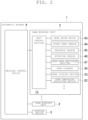
- FIG. 2 is a block diagram illustrating an electrical configuration of the automatic winder;
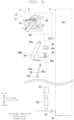
- FIG. 3 is a schematic front view of a yarn winding unit;
- FIG. 4 is a schematic side view of a part of the yarn winding unit in an up-down direction;
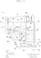
- FIG. 5 is a front view of a winding section;
- FIG. 6 is a view in which illustration of some members illustrated in FIG. 5 is omitted;
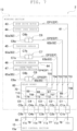
- FIG. 7 is a block diagram more specifically illustrating electrical connection between each section of the winding section and a unit control section;
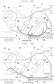
- FIGS. 8A and 8B are side views of a case body and a periphery thereof;
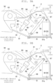
- FIGS. 9A and 9B are side views of the case body and a periphery thereof;
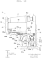
- FIG. 10 is an explanatory view illustrating removal of the winding section from a frame;
- FIG. 11 is an explanatory view illustrating removal of some components provided in the winding section; and
- FIG. 12 is a block diagram more specifically illustrating electrical connection between each section of the winding section and the unit control section according to an alternative embodiment.
DETAILED DESCRIPTION OF PREFERRED EMBODIMENTS
-
An embodiment of the present invention will be described. For convenience of description, as illustrated in FIG. 1, a direction in which a plurality of yarn winding units 2 to be described later are arranged is defined as a left-right direction (an arrangement direction of the present invention). A direction in which gravity acts is defined as an up-down direction. A direction orthogonal to both the left-right direction and the up-down direction is defined as a front-back direction (an orthogonal direction of the present invention). A front side corresponds to one side in the orthogonal direction of the present invention. A back side corresponds to another side in the orthogonal direction of the present invention.
(Schematic configuration of automatic winder)
-
First, a schematic configuration of an automatic winder 1 (a yarn winding machine of the present invention) according to the present embodiment will be described with reference to FIGS. 1 and 2. FIG. 1 is a front view of the automatic winder 1. FIG. 2 is a block diagram illustrating an electrical configuration of the automatic winder 1. The automatic winder 1 includes a plurality of yarn winding units 2, a doffing device 3, and a machine control device 4.
-
Each of the plurality of yarn winding units 2 is configured to wind a yarn Y pulled out from a yarn supplying bobbin Bs onto a winding bobbin Bw (see FIG. 3) to form a package P. The plurality of yarn winding units 2 are arranged in the left-right direction.
-
The doffing device 3 is configured to perform work (doffing) such as removing a fully-wound package P from the yarn winding unit 2 and attaching an empty winding bobbin Bw to the yarn winding unit 2. The doffing device 3 is disposed above the plurality of yarn winding units 2. The doffing device 3 is configured to be movable in the left-right direction. Upon receiving a signal indicating that the package P is fully wound from the yarn winding unit 2, the doffing device 3 is moved to above the yarn winding unit 2 to carry out the above-described work.
-
The machine control device 4 is disposed, for example, on the left side with respect to the plurality of yarn winding units 2. The machine control device 4 is electrically connected to a unit control section 15 of the yarn winding unit 2 and a control section (not illustrated) of the doffing device 3, and performs communication with these control sections.
-
Further, a work passage 5 extending in the left-right direction is provided on a front side (a front side in the page of the figure) with respect to the plurality of yarn winding units 2 and the machine control device 4. The work passage 5 is a passage for a worker to carry out various types of work on each yarn winding unit 2 or the machine control device 4. In the present embodiment, the work passage 5 includes, for example, a floor surface 5a and a space (a work space Sw to be described later) immediately above the floor surface 5a.
(Yarn winding unit)
-
Next, a configuration of the yarn winding unit 2 will be described with reference to FIGS. 2 to 5. FIG. 3 is a schematic front view of the yarn winding unit 2. FIG. 4 is a schematic side view of a part of the yarn winding unit 2 in the up-down direction. In FIG. 4, a right side in the page of the figure corresponds to the front side in the front-back direction, and the left side with respect to the page of the figure corresponds to the back side in the front-back direction. FIG. 5 is a front view of a winding section 13 described later.
-
As illustrated in FIG. 3, the yarn winding unit 2 includes a frame 10, a yarn supplying section 11, a yarn processing execution section 12, the winding section 13, and the unit control section 15 (a control device and an external device of the present invention). The frame 10 is a hollow columnar member extending in the up-down direction. An installation position of the frame 10 is fixed. The yarn supplying section 11, the yarn processing execution section 12, and the winding section 13 are provided and arranged on the frame 10 in this order from bottom to top. The unit control section 15 is accommodated inside the frame 10, for example.
-
The yarn supplying section 11 is configured to supply the yarn Y wound around the yarn supplying bobbin Bs while unwinding the yarn Y. The yarn supplying section 11 has a yarn supplying bobbin supporting section 21 and a yarn unwinding assisting device 22. The yarn supplying bobbin supporting section 21 supports the yarn supplying bobbin Bs in a substantially upright state. The yarn unwinding assisting device 22 regulates a bulge when the yarn Y is unwound from the yarn supplying bobbin Bs, with a regulating tube 23. The regulating tube 23 is configured to move downward as an amount of yarn wound around the yarn supplying bobbin Bs decreases, to maintain a size of the bulge at a constant size.
-
The yarn processing execution section 12 is for executing various processes regarding the yarn Y. The yarn processing execution section 12 includes a yarn feeler 31, a tension applying device 32, a yarn joining device 33, and a yarn clearer 34.
-
The yarn feeler 31 is configured to be able to detect the presence or absence of a travelling yarn Y between the yarn unwinding assisting device 22 and the tension applying device 32. The tension applying device 32 is configured to be able to apply a predetermined tension on the travelling yarn Y. As an example of the tension applying device 32, there is a tension applying device of a so-called gate type. As illustrated in FIG. 3, a plurality of fixed gate bodies 32a and a plurality of movable gate bodies 32b are alternately disposed in the up-down direction. By adjusting a position in a horizontal direction of the plurality of movable gate bodies 32b, a predetermined tension is applied to the yarn Y travelling between the fixed gate body 32a and the movable gate body 32b.
-
The yarn joining device 33 is configured to join the yarn Y (a lower yarn Y1) on the yarn supplying section 11 side and the yarn Y (an upper yarn Y2) on the winding section 13 side, in a state where the yarn Y is no longer connected between the yarn supplying section 11 and the winding section 13. As an example of the yarn joining device 33, there is a yarn joining device of a compressed air type. The yarn joining device 33 blows compressed air supplied from a compressed air source (not illustrated) to the lower yarn Y1 and the upper yarn Y2, to temporarily loosen both yarn ends. Thereafter, the yarn joining device 33 again blows compressed air to both yarn ends to entangle the yarn ends to perform the yarn joining operation.
-
Below the yarn joining device 33, a lower yarn catching and guiding section 35 that catches the lower yarn Y1 on the yarn supplying bobbin Bs side and guide the lower yarn Y1 to the yarn joining device 33 is provided. Above the yarn joining device 33, an upper yarn catching and guiding section 36 that catches the upper yarn Y2 on the package P side and guide the upper yarn Y2 to the yarn joining device 33 is provided. The lower yarn catching and guiding section 35 includes a shaft 35a, an arm 35b, and a suctioning section 35c. The shaft 35a extends, for example, along the left-right direction. The arm 35b is a pipe-shaped member rotatable about the shaft 35a. The suctioning section 35c is disposed at a distal end portion of the arm 35b. The suctioning section 35c is configured to be able to suction and catch a yarn end portion of the lower yarn Y1. The arm 35b is driven to turn by a motor 37. The upper yarn catching and guiding section 36 includes a shaft 36a, an arm 36b, and a suctioning section 36c. The shaft 36a extends, for example, along the left-right direction. The arm 36b is a pipe-shaped member rotatable about the shaft 36a. The suctioning section 36c is disposed at a distal end portion of the arm 36b. The suctioning section 36c is configured to be able to suction and catch a yarn end portion of the upper yarn Y2. The arm 36b is driven to turn by a motor 38.
-
At a time of the yarn joining operation by the yarn joining device 33, the upper yarn catching and guiding section 36 carries out the following operation. First, the arm 36b is rotationally driven by the motor 38 to turn upward. As a result, the suctioning section 36c is positioned near the package P. Next, the suctioning section 36c suctions and catches a yarn end portion of the upper yarn Y2 attached to a surface of the package P. After catching the upper yarn Y2, the arm 36b is rotationally driven by the motor 38 to turn downward. Thus, the upper yarn catching and guiding section 36 guides the upper yarn Y2 to the yarn joining device 33. Further, in the lower yarn catching and guiding section 35, the arm 35b is driven by the motor 37 to turn upward in a state where a yarn end portion of the lower yarn Y1 is caught by the suctioning section 35c. Thus, the lower yarn catching and guiding section 35 guides the lower yarn Y1 to the yarn joining device 33. The yarn joining device 33 joins the guided lower yarn Y1 and upper yarn Y2.
-
The yarn clearer 34 is configured to be able to acquire information about a thickness of the travelling yarn Y. The yarn clearer 34 detects a yarn defect on the basis of this information. A cutter 34a is disposed near the yarn clearer 34. When a yarn defect is detected by the yarn clearer 34, the cutter 34a immediately cuts the yarn Y. At substantially the same time, the yarn clearer 34 outputs a detection signal to the unit control section 15.
-
The winding section 13 is configured to be able to execute a winding operation of winding the yarn Y onto the winding bobbin Bw to form the package P. The winding section 13 is configured to be detachable from the frame 10 (details will be described later). As illustrated in FIGS. 2 to 5, the winding section 13 includes a cradle 41, a traverse drum 42, a drum drive motor 43, an upper yarn sensor 44, a traverse sensor 45, a rotation sensor 46, a yarn path switching section 47, a cover member 48, and a guide member 49. Each of the drum drive motor 43, the upper yarn sensor 44, the traverse sensor 45, the rotation sensor 46, and the yarn path switching section 47 is an electrical device operated by electricity.
-
The cradle 41 is configured to rotatably hold the winding bobbin Bw (the package P). The cradle 41 is configured to be swingable between a contact position (see a solid line in FIG. 4) and a separation position (see a two-dot chain line in FIG. 4). The contact position is a position of the cradle 41 when the package P is in contact with the traverse drum 42. The separation position is a position of the cradle 41 when the package P is separated from the traverse drum 42.
-
The traverse drum 42 (a contact drum of the present invention) is configured to rotate the package P, and is configured to traverse the travelling yarn Y. The traverse drum 42 is a substantially tubular member. A rotational axis direction of the traverse drum 42 is substantially parallel to the left-right direction. A traverse groove 42a is formed on an outer peripheral surface of the traverse drum 42. By rotating while being in contact with the surface of the package P, the traverse drum 42 causes the package P to be driven to rotate by a frictional force. At the same time, by rotating with the yarn Y passing through the traverse groove 42a, the traverse drum 42 traverses the yarn Y with a predetermined width. Thus, the yarn Y is wound around the winding bobbin Bw to form the package P. Hereinafter, for convenience of description, a region in which the yarn Y is traversed in the left-right direction is referred to as a traverse region Rt (see FIG. 3). The traverse region Rt is disposed, for example, at a position different from the frame 10 in the left-right direction. More specifically, the traverse region Rt is disposed, for example, on the left side with respect to the frame 10.
-
As schematically illustrated in FIG. 3, for example, two types of traverse grooves 42a are formed on an outer peripheral surface of the traverse drum 42. A first traverse groove 42a1 is configured such that the number of times the yarn Y is traversed becomes a predetermined first number of times when the traverse drum 42 makes one rotation. A second traverse groove 42a2 is configured such that the number of times the yarn Y is traversed becomes a second number of times, which is different from the first number of times, when the traverse drum 42 makes one rotation. The reason why the two types of traverse grooves 42a are formed in this manner will be described later.
-
The drum drive motor 43 (a drive source, a first device, and an electrical device of the present invention) is configured to rotationally drive the traverse drum 42. The drum drive motor 43 can rotationally drive the traverse drum 42 in both a forward direction and a reverse direction. The forward direction is a rotation direction of the traverse drum 42 when the yarn Y is wound around the winding bobbin Bw. The reverse direction is a rotation direction of the traverse drum 42 when the upper yarn Y2 is pulled out from the package P at the time of yarn joining. The drum drive motor 43 is electrically connected to the unit control section 15.
-
The upper yarn sensor 44 (a yarn pull-out detecting section, a second device, and the electrical device of the present invention) is configured to be able to detect the upper yarn Y2 being suctioned and caught by the suctioning section 36c of the upper yarn catching and guiding section 36. The upper yarn sensor 44 is, for example, a known reflective optical sensor. The upper yarn sensor 44 is electrically connected to the unit control section 15. The upper yarn sensor 44 is disposed on a side opposite to the frame 10 across the traverse region Rt (see FIG. 3) in the left-right direction. The upper yarn sensor 44 is detachably mounted to the winding section 13.
-
The traverse sensor 45 (a traverse detecting section, the second device, and the electrical device of the present invention) is configured to be able to detect whether or not the yarn Y is being normally traversed when the yarn Y is being wound around the winding bobbin Bw. The traverse sensor 45 is, for example, a known reflective optical sensor. The traverse sensor 45 is disposed, for example, on the front side with respect to the traverse drum 42. The traverse sensor 45 is disposed in the traverse region Rt (see FIG. 3) in the left-right direction. The traverse sensor 45 is electrically connected to the unit control section 15. The traverse sensor 45 is detachably mounted to the winding section 13.
-
The rotation sensor 46 (a rotation detecting section and an electrical device of the present invention) is configured to be able to detect a number of rotations of the winding bobbin Bw. The rotation sensor 46 includes, for example, a known rotary encoder. The rotation sensor 46 is mounted to the cradle 41. The rotation sensor 46 is electrically connected to the unit control section 15. The rotation sensor 46 is disposed, for example, on the left side with respect to the traverse region Rt (see FIG. 3). That is, the rotation sensor 46 is disposed on a side opposite to the frame 10 across the traverse region Rt (see FIG. 3) in the left-right direction.
-
The yarn path switching section 47 (the second device and the electrical device of the present invention) is configured to be able to temporarily switch a path (a yarn path) of the yarn Y between a predetermined first yarn path and a second yarn path different from the first yarn path. The yarn path switching section 47 includes, for example, a known pull solenoid or push solenoid. The yarn path switching section 47 is disposed inside the traverse region Rt (see FIG. 3) in the left-right direction. The yarn path switching section 47 is provided to temporarily switch a wind ratio during formation of the package P. The wind ratio is the number of rotations of the winding bobbin Bw while the traversed yarn Y reciprocates once in the left-right direction. For example, when the number of rotations of the traverse drum 42 is substantially constant, the wind ratio gradually decreases following an increase in winding amount in the package P. When the wind ratio becomes a predetermined value (for example, substantially the same as an integer), the yarn Y is wound in an overlapping manner at the same position on a surface of the package P. Such a phenomenon is known as so-called ribbon winding. When the ribbon winding occurs in the package P, a problem of unwinding failure occurs at a time of unwinding the yarn Y from the package P in a subsequent process. Therefore, the yarn path switching section 47 can temporarily switch a state of the yarn Y between a state where the yarn Y is passing through the first traverse groove 42a1 and a state where the yarn Y is passing through the second traverse groove 42a2 different from the first traverse groove 42a1, in the two types of traverse grooves 42a. Thus, for example, the yarn Y can be temporarily transferred from the first traverse groove 42a1 to the second traverse groove 42a2 before the wind ratio reaches the predetermined value described above. Therefore, the wind ratio can be temporarily greatly changed. Therefore, occurrence of ribbon winding can be inhibited. The yarn path switching section 47 is detachably mounted to the winding section 13.
-
As described above, the traverse sensor 45 and the yarn path switching section 47 are disposed inside the traverse region Rt (see FIG. 3) in the left-right direction. Further, the upper yarn sensor 44 and the rotation sensor 46 are disposed on a side opposite to the frame 10 across the traverse region Rt (see FIG. 3) in the left-right direction.
-
The cover member 48 is a plate-shaped member that covers both end portions of the traverse drum 42 in the left-right direction. The cover member 48 is disposed on the front side with respect to the traverse drum 42. The cover member 48 is curved along an outer peripheral surface of the traverse drum 42.
-
The guide member 49 is a member that guides the yarn Y to the traverse drum 42. The guide member 49 is disposed on the front side with respect to the traverse drum 42.
-
As illustrated in FIG. 4, the work space Sw is formed on the front side with respect to the yarn winding unit 2. The work space Sw is a space formed in the work passage 5. More specifically, the work space Sw is, for example, a space directly above the floor surface 5a. The work space Sw is, for example, a space in which a worker can perform work of attaching and detaching the winding section 13 to and from the frame 10. A rear end of the work passage 5 is defined by, for example, a portion (the floor surface 5a in the present embodiment) that can be stepped on by the worker. The work passage 5 of the present embodiment does not mean only the floor surface 5a, but includes a place (that is, the work space Sw) which is formed above the floor surface 5a and through which the worker can pass. Further, the portion stepped on by the worker is not limited to the floor surface 5a. For example, the work passage 5 may be defined by a floor plate, a tread plate, or the like (not illustrated).
-
As illustrated in FIG. 4, an access space Sa is formed on the back side with respect to the work space Sw. In the present embodiment, the access space Sa is a space that can be accessed from the front side by the worker when the winding section 13 is located at the operation position. The operation position is a position of the winding section 13 when the winding section 13 can execute the winding operation (a more specific definition will be described later). A member disposed in the access space Sa is a member which is included in the winding section 13 and can be accessed from the work passage 5 in the front-back direction by the worker when the winding section 13 is located at the operation position.
-
Although not illustrated in FIG. 3, for example, a display section 14 (see FIG. 1) to display information relating to a state and the like of the yarn winding unit 2 is provided on a front surface of an upper portion of the frame 10. The display section 14 is electrically connected to the unit control section 15 (not illustrated).
-
The unit control section 15 is accommodated inside the frame 10, for example. The unit control section 15 includes, for example, a CPU, a ROM, and a RAM. The unit control section 15 includes a printed circuit board 15a to which the CPU, the ROM, and the R_AM are fixed. The unit control section 15 controls each section with the CPU in accordance with a program stored in the ROM. More specifically, the unit control section 15 controls the yarn unwinding assisting device 22, the yarn joining device 33, the drum drive motor 43, the yarn path switching section 47, the display section 14, and the like. Further, the unit control section 15 receives signals from the yarn clearer 34, the upper yarn sensor 44, the traverse sensor 45, the rotation sensor 46, and the like. Further, the unit control section 15 outputs a signal for requesting the doffing device 3 to perform doffing via the machine control device 4.
-
In the yarn winding unit 2 having the above configuration, the package P is formed as follows. That is, the unit control section 15 drives the drum drive motor 43 to rotate the traverse drum 42 in a state where the package P and the traverse drum 42 are in contact with each other. As a result, the yarn Y pulled out from the yarn supplying bobbin Bs is wound around the winding bobbin Bw, and the package P is formed.
(Configuration for attaching and detaching winding section to and from frame)
-
A configuration for attaching and detaching the winding section 13 to and from the frame 10 will be described with reference to FIGS. 5 and 6. FIG. 6 is a view in which illustration of some members illustrated in FIG. 5 is omitted. More specifically, in FIG. 6, illustration of the cover member 48, the guide member 49, and a front cover 52 (a cover of the present invention) to be described later is omitted. In FIG. 6, it is assumed that the front cover 52 is removed from a case body 51. In FIG. 6, the cover member 48 and the guide member 49 may not be removed from the winding section 13.
-
As illustrated in FIG. 5, the winding section 13 includes a case 50 (a support section of the present invention). The case 50 is a box-shaped member. The case 50 is detachably mounted to an upper end of the frame 10. The cradle 41, the traverse drum 42, the drum drive motor 43, and the like are mounted to and supported by the case 50. The case 50 includes, for example, the case body 51, the front cover 52, and a right side cover (not illustrated).
-
The case body 51 is a box-shaped member. On a front surface of the case body 51, for example, an opening 51a for connection between an inside of the case body 51 and the work space Sw is formed. A mounting plate 51b having a substantially horizontal plate shape is provided at a lower end of the case body 51. The mounting plate 51b is detachably mounted to the frame 10 by, for example, a plurality of bolts B (a connecting member of the present invention) . The bolt B is disposed outside the case body 51, for example. The entire winding section 13 can be removed from the frame 10 by removing the case 50 from the frame 10, and further disconnecting electrical connection between the winding section 13 and the unit control section 15 as described later.
-
The front cover 52 is configured to cover a front surface of the case body 51. The front cover 52 is configured to protect a member disposed near the front surface of the case body 51. The front cover 52 is detachable from and attachable to the case body 51. The front cover 52 is configured to close the opening 51a, for example. The right side cover (not illustrated) is configured to cover a right side surface of the case body 51. In a state where the front cover 52 is removed from the case body 51, a worker can access the opening 51a and a nearby space from the front side. In other words, the front cover 52 is disposed between the work space Sw and the access space Sa (more specifically, a first access space Sa1 to be described later) in the front-back direction. That is, the front cover 52 is disposed so as to face the work passage 5 in the front-back direction.
-
Here, a more strict definition of the above-described operation position will be described. The operation position is a position of the plurality of electrical devices described above in a state where the plurality of electrical devices are mounted to the case body 51, the case body 51 is mounted to the frame 10, and the winding section 13 can execute the winding operation. In other words, regardless of whether or not the front cover 52 is mounted to the case body 51, it can be said that the plurality of electrical devices are located at the operation position as long as the winding operation can be executed by the plurality of electrical devices.
-
The winding section 13 can be moved between the operation position and the removal position. The removal position is any position after the winding section 13 is removed from the frame 10.
-
As illustrated in FIG. 6, the access space Sa includes the first access space Sa1, a second access space Sa2, and a third access space Sa3. The first access space Sa1 is a space at and near the opening 51a. The first access space Sa1 is formed immediately below the drum drive motor 43 and on the front side with respect to the drum drive motor 43. The first access space Sa1 is a space accessible from the front side (the work space Sw side) in a state where the front cover 52 is removed from the case body 51. The second access space Sa2 is formed inside the traverse region Rt (see FIG. 3) where the yarn Y is traversed, and on a side opposite to the frame 10 across the traverse region Rt in the left-right direction. The third access space Sa3 is a space in which the plurality of bolts B are disposed. That is, the plurality of bolts B can be accessed from the work passage 5 in a state where the electrical device is located at the operation position.
-
Although not illustrated, the winding section 13 may be pulled out to a position (hereinafter, a front side position) on the front side with respect to the operation position in a state where the corresponding yarn winding unit 2 is not operated and where the winding section 13 is mounted to the frame 10. In a state where the winding section 13 is located at the front side position, for example, the right side cover (not illustrated) can be attached to and detached from the case body 51.
(Further details of electrical configuration of winding section)
-
In order to reduce time and effort involved in the work of attaching and detaching the winding section 13 to and from the frame 10, the winding section 13 is configured as follows. Further details of the electrical configuration of the winding section 13 will be described with reference to FIGS. 6 to 8B. FIG. 7 is a block diagram more specifically illustrating electrical connection between each section of the winding section 13 and the unit control section 15. FIGS. 8A and 8B are side views of the case body 51 and a periphery thereof. In FIGS. 8A and 8B, it is assumed that the right side cover (not illustrated) is removed. Further, in FIGS. 8A and 8B, illustration of an upper portion of the cradle 41 is omitted (see two-dot chain lines in FIGS. 8A and 8B).
-
Some components (the drum drive motor 43 to the yarn path switching section 47) of the winding section 13 are illustrated in a frame of a two-dot chain line illustrated in FIG. 7. Each of the drum drive motor 43 to the yarn path switching section 47 (that is, the plurality of electrical devices) is electrically connected to the unit control section 15 via a plurality of wiring lines and one or more connector pairs. The plurality of wiring lines include a power supply line. The plurality of wiring lines include a signal line (an input line and/or an output line). Hereinafter, the power supply line and the signal line provided corresponding to one electrical device are collectively referred to as a wiring group. The connector pair is a known pair of connectors (couplers) detachable from each other. For simplification of description, in the present embodiment, it is assumed that one wiring group is fixed to one connector. Further, for convenience of description, a path that electrically connects each electrical device and the unit control section 15 is referred to as an electrical path EP. In each of the plurality of electrical paths EP (electrical paths EP1 to EP5), a side closer to the electrical device is referred to as a "device side". In addition, a side closer to the unit control section 15 in each electrical path EP is referred to as a "control-section side" (an external-device side of the present invention). That is, the connector pair includes a device-side connector and a control-section-side connector (an external-side connector of the present invention).
-
The winding section 13 includes a relay board 60 (a relay section of the present invention) disposed between the electrical device and the unit control section 15 in the electrical path EP. The relay board 60 may be, for example, a general printed circuit board, but is not limited thereto. The relay board 60 is accommodated, for example, in the case 50 (see FIGS. 8A and 8B). The relay board 60 is mounted to and supported by the case body 51 by using, for example, a screw (not illustrated). Conductive terminals T01 to T10 are provided on the relay board 60.
-
As illustrated in FIG. 7, conductive terminals T11 to T15 are provided on the printed circuit board 15a of the unit control section 15.
-
As illustrated in FIG. 7, the drum drive motor 43 is electrically connected to the unit control section 15 via a wiring group 61, a wiring group 66, a wiring group 71, a connector pair C1, and a wiring group 76. The wiring group 61 includes, for example, a plurality of wiring cables (not illustrated). This similarly applies wiring groups 62 to 65 described later.
-
As illustrated in FIG. 7, an end portion of the wiring group 61 on the device side is fixed to the drum drive motor 43. An end portion of the wiring group 61 on the control-section side is fixed to the terminal T01 of the relay board 60. The wiring group 61 may be detachable from the terminal T01. Similarly, the wiring groups 62 to 65 are fixed respectively to the terminals T02 to T05. The wiring groups 62 to 65 may be detachable respectively from the terminals T02 to T05.
-
The wiring group 66 includes a plurality of wiring lines (not illustrated). The wiring group 66 is fixed to, for example, the relay board 60. Alternatively, the wiring group 66 may be formed on the relay board 60, for example. This similarly applies wiring groups 67 to 70 described later. The wiring group 66 extends from the terminal T01 to the terminal T06.
-
The wiring group 71 includes, for example, a plurality of wiring cables (not illustrated). This similarly applies wiring groups 72 to 75 described later.
-
An end portion of the wiring group 71 on the device side is fixed to the terminal T06. The wiring group 71 may be detachable from the terminal T06. Similarly, the wiring groups 72 to 75 are fixed respectively to the terminals T07 to T10. The wiring groups 72 to 75 may be detachable respectively from the terminals T07 to T10.
-
The connector pair C1 is disposed between the wiring group 71 and the wiring group 76 in the electrical path EP1. The connector pair C1 includes a device-side connector C1a and a control-section-side connector C1b. An end portion of the wiring group 71 on the control-section side is fixed to the device-side connector C1a of the connector pair C1.
-
The wiring group 76 includes, for example, a plurality of wiring cables (not illustrated). This similarly applies wiring groups 77 to 80 described later. An end portion of the wiring group 76 on the device side is fixed to the control-section-side connector C1b. An end portion of the wiring group 76 on the control-section side is fixed to the terminal T11. The wiring group 76 may be detachable from the terminal T11. Similarly, the wiring groups 77 to 80 are fixed respectively to the terminals T12 to T15. The wiring groups 77 to 80 may be detachable respectively from the terminals T12 to T15.
-
As illustrated in FIG. 7, the upper yarn sensor 44 is electrically connected to the unit control section 15 via the wiring group 62, the wiring group 67, the wiring group 72, a connector pair C2, and the wiring group 77. The wiring group 62 is divided into a wiring group 62a on the device side and a wiring group 62b on the control-section side. An end portion of the wiring group 62a on the device side is fixed to the upper yarn sensor 44. In the electrical path EP2, a connector pair C6 is provided between the wiring group 62a and the wiring group 62b. The connector pair C6 includes a device-side connector C6a and a control-section-side connector C6b. An end portion of the wiring group 62a on the control-section side is fixed to the device-side connector C6a of the connector pair C6. An end portion of the wiring group 62b on the device side is fixed to the control-section-side connector C6b. An end portion of the wiring group 62b on the control-section side is fixed to the terminal T02. The wiring group 67 extends from the terminal T02 to the terminal T07. An end portion of the wiring group 72 on the device side is fixed to the terminal T07. The connector pair C2 is disposed between the wiring group 72 and the wiring group 77 in the electrical path EP2. The connector pair C2 includes a device-side connector C2a and a control-section-side connector C2b. An end portion of the wiring group 72 on the control-section side is fixed to the device-side connector C2a of the connector pair C2. An end portion of the wiring group 77 on the device side is fixed to the control-section-side connector C2b. An end portion of the wiring group 77 on the control-section side is fixed to the terminal T12.
-
As illustrated in FIG. 7, the traverse sensor 45 is electrically connected to the unit control section 15 via the wiring group 63, the wiring group 68, the wiring group 73, a connector pair C3, and the wiring group 78. The wiring group 63 is divided into a wiring group 63a on the device side and a wiring group 63b on the control-section side. An end portion of the wiring group 63a on the device side is fixed to the traverse sensor 45. In the electrical path EP3, a connector pair C7 is provided between the wiring group 63a and the wiring group 63b. The connector pair C7 includes a device-side connector C7a and a control-section-side connector C7b. An end portion of the wiring group 63a on the control-section side is fixed to the device-side connector C7a of the connector pair C7. An end portion of the wiring group 63b on the device side is fixed to the control-section-side connector C7b. An end portion of the wiring group 63b on the control-section side is fixed to the terminal T03. The wiring group 68 extends from the terminal T03 to the terminal T08. An end portion of the wiring group 73 on the device side is fixed to the terminal T08. The connector pair C3 is disposed between the wiring group 73 and the wiring group 78 in the electrical path EP3. The connector pair C3 includes a device-side connector C3a and a control-section-side connector C3b. An end portion of the wiring group 73 on the control-section side is fixed to the device-side connector C3a of the connector pair C3. An end portion of the wiring group 78 on the device side is fixed to the control-section-side connector C3b. An end portion of the wiring group 78 on the control-section side is fixed to the terminal T13.
-
As illustrated in FIG. 7, the rotation sensor 46 is electrically connected to the unit control section 15 via the wiring group 64, the wiring group 69, the wiring group 74, a connector pair C4, and the wiring group 79. An end portion of the wiring group 64 on the device side is fixed to the rotation sensor 46. An end portion of the wiring group 64 on the control-section side is fixed to the terminal T04. The wiring group 69 extends from the terminal T04 to the terminal T09. An end portion of the wiring group 74 on the device side is fixed to the terminal T09. The connector pair C4 is disposed between the wiring group 74 and the wiring group 79 in the electrical path EP4. The connector pair C4 includes a device-side connector C4a and a control-section-side connector C4b. An end portion of the wiring group 74 on the control-section side is fixed to the device-side connector C4a of the connector pair C4. An end portion of the wiring group 79 on the device side is fixed to the control-section-side connector C4b. An end portion of the wiring group 79 on the control-section side is fixed to the terminal T14.
-
As illustrated in FIG. 7, the yarn path switching section 47 is electrically connected to the unit control section 15 via the wiring group 65, the wiring group 70, the wiring group 75, a connector pair C5, and the wiring group 80. The wiring group 65 is divided into a wiring group 65a on the device side and a wiring group 65b on the control-section side. An end portion of the wiring group 65a on the device side is fixed to the yarn path switching section 47. In the electrical path EP5, a connector pair C8 is provided between the wiring group 65a and the wiring group 65b. The connector pair C8 includes a device-side connector C8a and a control-section-side connector C8b. An end portion of the wiring group 65a on the control-section side is fixed to the device-side connector C8a of the connector pair C8. An end portion of the wiring group 65b on the device side is fixed to the control-section-side connector C8b. An end portion of the wiring group 65b on the control-section side is fixed to the terminal T05. The wiring group 70 extends from the terminal T05 to the terminal T10. An end portion of the wiring group 75 on the device side is fixed to the terminal T10. The connector pair C5 is disposed between the wiring group 75 and the wiring group 80 in the electrical path EP5. The connector pair C5 includes a device-side connector C5a and a control-section-side connector C5b. An end portion of the wiring group 75 on the control-section side is fixed to the device-side connector C5a of the connector pair C5. An end portion of the wiring group 80 on the device side is fixed to the control-section-side connector C5b. An end portion of the wiring group 80 on the control-section side is fixed to the terminal T15.
-
The plurality of connector pairs C1 to C5 are disposed between the relay board 60 and the unit control section 15 in the electrical paths EP1 to EP5, respectively. Each of the plurality of connector pairs C1 to C5 corresponds to an intervening connector pair of the present invention.
-
As illustrated in FIG. 7, the device-side connectors C1a to C5a of the connector pair C1 to C5 are included in the winding section 13. The control-section-side connectors C1b to C5b are not included in the winding section 13.
-
The plurality of wiring groups 61 to 75 are fixed to the relay board 60. The plurality of wiring groups 61 to 75 correspond to a plurality of wiring members of the present invention.
(Specific dispose positions of connector pairs and the like)
-
Next, positions where the connector pairs C1 to C8 and the like are specifically disposed will be described with reference to FIGS. 6, 8A, and 8B. Note that, FIGS. 8A and 8B each illustrate only some of the plurality of wiring groups accommodated in the case 50.
-
As illustrated in FIG. 6, the connector pairs C1 to C8 are provided in the access space Sa. In other words, the worker can access the connector pair C1 to C8 from the work space Sw (see FIG. 4) in a state where the electrical device such as the drum drive motor 43 is located at the operation position in the winding section 13. That is, the connector pair C1 to C8 can be accessed from the work passage 5 in a state where the electrical device is located at the operation position. More specifically, the connector pairs C1 to C5 are provided in the first access space Sa1. Hereinafter, a more specific example of dispose positions of the connector pairs C1 to C5 will be described. First, an axial center of a rotational axis (not illustrated) of the drum drive motor 43 (hereinafter, referred to as a rotational axis center PC, see FIGS. 8A and 8B) extends substantially parallel to the left-right direction. A virtual plane VP (see FIGS. 8A and 8B) including the rotational axis center PC and being parallel to the up-down direction is defined. For example, the connector pairs C1 to C5 are disposed on the front side (that is, a side closer to the work passage 5 in the front-back direction) with respect to the virtual plane VP. Note that, in FIG. 6, only the connector pairs C1 to C3 among the connector pairs C1 to C5 are illustrated in order to avoid complication of the drawing. In a state where the front cover 52 is removed from the case body 51, the worker can access the connector pairs C1 to C5 from the front side (the side closer to the work passage 5).
-
The connector pair C1 is for electrically connecting the drum drive motor 43 and the unit control section 15. The connector pair C1 corresponds to a first connector pair of the present invention. As described above, the connector pair C1 is disposed at the same position as the drum drive motor 43, or at a position closer to the work space Sw than the drum drive motor 43, in the front-back direction.
-
The connector pair C2 is disposed between the connector pair C6 and the unit control section 15 in the electrical path EP2. Similarly, in the electrical path EP3, the connector pair C3 is disposed between the connector pair C7 and the unit control section 15, and in the electrical path EP5, the connector pair C5 is disposed between the connector pair C8 and the unit control section 15. The connector pairs C2, C3, and C5 are disposed at positions closer to the frame 10 than the connector pairs C6 to C8 (in other words, a position closer to the connector pair C1) in the left-right direction. Each of the connector pairs C2, C3, and C5 corresponds to a third connector pair of the present invention.
-
The connector pairs C6 to C8 are provided in the second access space Sa2. That is, the connector pairs C6 to C8 are disposed inside the traverse region Rt (see FIG. 3), or on a side opposite to the frame 10 across the traverse region Rt in the left-right direction. In other words, the connector pairs C6 to C8 are disposed at positions closer to the corresponding electrical devices than the frame 10, in the left-right direction. The connector pairs C6 to C8 correspond to a second connector pair of the present invention.
-
Further, when a ground wire (not illustrated) is mounted to at least one of the plurality of electrical devices, a terminal of the ground wire on the ground side is preferably disposed in the access space Sa (that is, a position accessible from the work passage 5 in the front-back direction).
-
The relay board 60 is accommodated in the case 50 as described above. More specifically, the relay board 60 is disposed near a rear end portion of an internal space of the case body 51. The relay board 60 is disposed right above the mounting plate 51b. The relay board 60 is disposed at a position farther from the drum drive motor 43 than the connector pair C1 to C5. The relay board 60 is disposed at a position as far as possible from the drum drive motor 43. As a result, vibration during the operation of the drum drive motor 43 can be attenuated as much as possible until the vibration is transmitted to the relay board 60. As a result, damage to the terminals T01 to T10 (that is, a connecting section between the relay board 60 and the wiring groups 61 to 70) provided on the relay board 60 can be suppressed.
-
The plurality of bolts B that fix (connect) the mounting plate 51b to the frame 10 include a bolt B1 (a fixing member of the present invention, see FIG. 8A and FIG. 8B) disposed near the relay board 60. Preferably, a shortest distance between the bolt B1 and the relay board 60 is shorter than a shortest distance between the bolt B1 and the drum drive motor 43. The bolt B1 and the relay board 60 are disposed at positions as close as possible to each other. As a result, a portion of the case body 51 closer to the relay board 60 is firmly fixed to the frame 10 (such a portion is hereinafter referred to as a fixed portion). The fixed portion has higher rigidity than a state without fixing to the frame 10. For this reason, in general, vibration of the fixed portion is easily suppressed. Therefore, vibration of the relay board 60 caused by vibration of the drum drive motor 43 can be suppressed.
-
As illustrated in FIG. 8A, the case body 51 is provided with, for example, a connection hole 81 and a connection hole 82. The connection hole 81 and the connection hole 82 are holes to connect an inside and an outside of the case body 51. The connection hole 81 is provided at a left end portion of the case body 51, for example. The connection hole 81 is provided, for example, on a front portion of the left end portion of the case body 51. The wiring groups 62b, 63b, and 65b are partially accommodated in the case body 51 through the connection hole 81. The wiring groups 62b, 63b, and 65b extend up to the relay board 60. The connection hole 82 is provided, for example, at a central portion of the case body 51 in the front-back direction. The wiring group 64 is partially accommodated in the case body 51 through the connection hole 82. The wiring group 64 extends up to the relay board 60. Further, as illustrated in FIG. 8B, the wiring groups 71 to 75 extend forward from the relay board 60.
-
The wiring groups 76 to 80 extend from the first access space Sa1 to the unit control section 15 in the frame 10. The frame 10 has, for example, a passing hole (not illustrated) for allowing the wiring groups 76 to 80 to pass through. The passing hole is formed, for example, on an upper surface, a front surface, or a side surface of the frame 10.
(Other configurations)
-
Next, other configurations of the winding section 13 will be described with reference to FIGS. 9A and 9B. FIGS. 9A and 9B are side views of the case body 51 and a periphery thereof, similar to FIGS. 8A and 8B. In FIGS. 9A and 9B, illustration of an upper portion of the cradle 41 is omitted.
-
As illustrated in FIGS. 9A and 9B, inside the case body 51, a moving mechanism 90 that moves the cradle 41 between the contact position and the separation position is provided. The moving mechanism 90 is disposed on the front side with respect to the relay board 60, for example. The moving mechanism 90 includes, for example, a swing member 91, an air cylinder 92, and a spring 93.
-
The swing member 91 is, for example, a plate member having a substantially L shape when viewed from the left-right direction. The swing member 91 is swingable about a swing shaft 94 extending in the left-right direction. The swing member 91 extends, for example, substantially in the front-back direction. The swing member 91 is connected to the cradle 41 in an integrally swingable manner via the swing shaft 94. For example, a piston rod 95 of the air cylinder 92 described later is mounted to a portion (a front end portion) of the swing member 91 on the front side with respect to the swing shaft 94. A hook section 97 to which the spring 93 is mounted, for example, is formed in a portion (a rear end portion) of the swing member 91 on the back side with respect to the swing shaft 94. The air cylinder 92 is configured to be able to expand and contract the piston rod 95. The air cylinder 92 is disposed on the front side with respect to the swing member 91, for example. A rod end 96 of the piston rod 95 is mounted to, for example, a front end portion of the swing member 91. In FIGS. 9A and 9B, the piston rod 95 is in a contracted state. The spring 93 is, for example, a known extension coil spring. The spring 93 is configured to apply a tensile force to the swing member 91. One end portion of the spring 93 is hooked on the hook section 97. Another end portion of the spring 93 is hooked on a hook section 98, for example. The hook section 98 is provided, for example, in a lower part of the case body 51. The spring 93 applies a tensile force to the swing member 91 by an elastic restoring force. A hook section 99 having a configuration similar to that of the hook section 98 is provided near the hook section 98 (for example, on an immediate front side with respect to the hook section 98) . A distance between the hook section 99 and the hook section 97 is larger than, for example, a distance between the hook section 98 and the hook section 97. Further, an inclination angle of the spring 93 with respect to the swing member 91 is mutually different between when the other end portion of the spring 93 is hooked on the hook section 98 and when the other end portion is hooked on the hook section 99. The elastic restoring force of the spring 93 is mutually different between when the other end portion of the spring 93 is hooked on the hook section 98 and when the other end portion is hooked on the hook section 99. The reason why the hook section 99 is provided will be described later.
-
When the piston rod 95 is contracted as illustrated in FIG. 9A, the cradle 41 is located at the contact position. At this time, a predetermined contact pressure is applied to the package P by a reaction force from the traverse drum 42. More specifically, when a weight of the cradle 41 and a weight of the package P are large, the contact pressure is large. A contraction force of the piston rod 95 increases the contact pressure. A tensile force by the spring 93 reduces the contact pressure. Magnitude of the contact pressure is related to these forces. Whereas, when the piston rod 95 extends, the swing member 91 is swung about the swing shaft 94. As a result, the cradle 41 is forcibly moved to the separated position.
(Method of attaching and detaching winding section)
-
Next, a method of attaching and detaching the winding section 13 to and from the frame 10 will be described with reference to FIG. 10. FIG. 10 is an explanatory view illustrating removal of the winding section 13 from the frame 10.
-
In a state where the operation of the winding section 13 is stopped, the worker removes the front cover 52 (see FIG. 5) from the case body 51. Next, the worker accesses the first access space Sa1 (see FIG. 6) in a state where the winding section 13 is located at the operation position. The worker separates between the device-side connectors C1a to C5a and the control-section-side connectors C1b to C5b (see FIG. 10). Note that FIG. 10 illustrates only the device-side connectors C1a to C3a and the control-section-side connectors C1b to C3b among these connectors. Next, the worker accesses the third access space Sa3 (see FIG. 6) and removes the plurality of bolts B fixing the case 50 to the frame 10. Accordingly, the case 50 can be separated from the frame 10. Further, since the device-side connectors C1a to C5a and the control-section-side connectors C1b to C5b are in the separated state, the entire winding section 13 including the case 50 can be removed from the frame 10 (see FIG. 10). Thus, the entire winding section 13 can be moved to the removal position. Further, the worker can attach the entire winding section 13 to the frame 10 by performing work in a procedure reverse to the series of operations described above. In the present embodiment, the entire winding section 13 corresponds to the detachable section of the present invention.
(Method of attaching and detaching some components)
-
Next, a method of attaching and detaching some of the plurality of components constituting the winding section 13 to and from the winding section 13 will be described with reference to FIG. 11. FIG. 11 is an explanatory view illustrating removal of some components provided in the winding section 13. The worker accesses the second access space Sa2 (see FIG. 6) in a state where the winding section 13 is located at the operation position. For example, the worker separates the device-side connector C6a and the control-section-side connector C6b from each other. As a result, the upper yarn sensor 44, the wiring group 62a, and the device-side connector C6a can be removed from the winding section 13. The worker may separate the device-side connector C7a and the control-section-side connector C7b from each other. As a result, the traverse sensor 45, the wiring group 63a, and the device-side connector C7a can be removed from the winding section 13. The worker may separate the device-side connector C8a and the control-section-side connector C8b from each other. As a result, the yarn path switching section 47, the wiring group 65a, and the device-side connector C8a can be removed from the winding section 13. In the present embodiment, each of the upper yarn sensor 44, the traverse sensor 45, and the yarn path switching section 47 also corresponds to the detachable section of the present invention.
(Reason why hook section is provided)
-
The hook section 99 described above is provided for the following reason. Although a detailed description is omitted, for example, the cradle 41, the traverse drum 42, and the drum drive motor 43 may be configured to be removable from the case 50, in a state where the winding section 13 is located at the front side position and the right side cover (not illustrated) of the case 50 is removed. Further, for example, a cradle (not illustrated) to which a motor (not illustrated) that directly rotationally drives the package P is mounted, a traverse device (not illustrated) that traverses the yarn Y, and the contact drum (not illustrated) that applies a contact pressure to the package P may be mounted to the case 50. In such a configuration, the cradle (not illustrated) is heavier than the cradle 41. Therefore, the contact pressure applied to the package P may become larger than the intended contact pressure. Therefore, the contact pressure can be adjusted by moving the other end portion of the spring 93 from the hook section 98 to the hook section 99 (see FIG. 9B). More specifically, at least elongation of the spring 93 when the other end portion of the spring 93 is hooked on the hook section 99 is larger than elongation of the spring 93 when the other end portion of the spring 93 is hooked on the hook section 98. As a result, the elastic restoring force can be increased at least when the other end portion of the spring 93 is hooked on the hook section 98. The elastic restoring force and the gravity applied to the cradle (not illustrated) described above are offset to some extent. Therefore, when a weight of the cradle is changed, the contact pressure can be adjusted without replacing the air cylinder 92 and the spring 93.
-
As described above, even if the winding section 13 is not moved from the operation position, the worker can access the connector pair C1 to C8 from the work passage 5. As a result, it is possible to easily perform the attaching and detaching work between the device-side connector and the control-section-side connector. Therefore, in the yarn winding unit 2, time and effort involved in the work of attaching and detaching the winding section 13 to and from the frame 10 can be reduced.
-
Further, the connector pair C1 (and the connector pairs C2 to C5) is disposed on a side closer to the work passage 5 than the virtual plane VP in the front-back direction. Therefore, it is possible to suppress the drum drive motor 43 from becoming an obstacle at a time of accessing the connector pair C1 and the like from the work passage 5.
-
Further, the front cover 52 is disposed to face the work passage 5 in the front-back direction, and is configured to be detachable from the yarn winding unit 2. Thus, the work of removing the front cover 52 from the yarn winding unit 2 in the work passage 5 can be carried out. Therefore, even when the first access space Sa1 is separated from the work passage 5 by the front cover 52, the connector pair C1 to C8 can be easily accessed from the work passage 5.
-
Further, the connector pairs C6 to C8 are disposed at positions closer to the corresponding electrical devices than the frame 10 in the left-right direction. As a result, a wiring line connecting the upper yarn sensor 44 and the device-side connector C6a can be shortened as compared with a case where the connector pairs C6 to C8 are provided in the frame 10 or in the vicinity of the frame 10. This similarly applies to the traverse sensor 45 and the yarn path switching section 47. Therefore, when it is desired to attach and detach only the upper yarn sensor 44, the traverse sensor 45, or the yarn path switching section 47 to and from the yarn winding unit 2, the attaching and detaching work can be easily carried out.
-
Further, the upper yarn sensor 44 can be attached to and detached from the yarn winding unit 2 by removing any one of the connector pair C2 and the connector pair C6 in accordance with a situation. This similarly applies to the traverse sensor 45 and the yarn path switching section 47.
-
Further, in the present embodiment, the upper yarn sensor 44, the traverse sensor 45, and the yarn path switching section 47 can be easily attached to and detached from the yarn winding unit 2.
-
Further, in the present embodiment, it is possible to easily access the connector pair C4 that electrically connects the rotation sensor 46 and the unit control section 15.
-
In addition, when the number of electrical devices is large as in the present embodiment, the number of wiring lines increases, and the configuration of the winding section 13 may become complicated. In this regard, in the present embodiment, the wiring lines can be integrated on the relay board. Therefore, complication of the configuration of the winding section 13 can be suppressed.
-
Further, the relay board 60 is disposed at a position farther from the drum drive motor 43 than the plurality of connector pairs C1 to C5. As described above, since the relay board 60 is disposed at a position relatively far from the drum drive motor 43, vibration of the drum drive motor 43 can be attenuated until the vibration is transmitted to the relay board 60. Therefore, it is possible to suppress damage on the connecting section between the relay board 60 and the plurality of wiring groups 61 to 70.
-
Further, a shortest distance between the bolt B1 and the relay board 60 is shorter than a shortest distance between the bolt B1 and the drum drive motor 43. Therefore, as described above, vibration of the relay board 60 caused by vibration of the drum drive motor 43 can be suppressed.
-
Further, even in a state where the winding section 13 is removed from the frame 10, a state where the unit control section 15 is mounted to the frame 10 can be maintained. Therefore, when the winding section 13 is replaced, the unit control section 15 does not need to be replaced together.
-
Further, the plurality of bolts B are provided to be accessible from the work passage 5. Therefore, each bolt B can also be easily accessed. Therefore, the winding section 13 can be more easily attached to and detached from the frame 10.
-
Next, alternative embodiments in which modifications are made on the above-described embodiment will be described. However, components having configurations similar to those in the embodiment described above are denoted by the same reference numerals, and the description thereof will be appropriately omitted.
- (1) In the embodiment described above, the connector pairs C1 to C5, whose number is the same as the number of electrical devices, are disposed between the relay board 60 and the unit control section 15 in the electrical paths EP1 to EP5. However, the present invention is not limited thereto. A common connector pair (not illustrated) may be provided instead of some or all of the plurality of connector pairs C1 to C5. The common connector pair includes a common device-side connector (not illustrated) and a common control-section-side connector (not illustrated). Some or all of the plurality of wiring groups 71 to 75 may be fixed to the common device-side connector. Some or all of the plurality of wiring groups 76 to 80 may be fixed to the common control-section-side connector.
- (2) In the embodiment described above, the winding section 13 includes the traverse sensor 45. Instead of the traverse sensor 45, the winding section 13 may include, for example, a drum feeler 100 (a winding detecting section, the second device, and the electrical device of the present invention, see FIG. 12). The drum feeler 100 is configured to be able to detect whether or not the yarn Y is wound around the traverse drum 42. The drum feeler 100 includes, for example, a switch device (not illustrated). The switch device includes, for example, a lever (not illustrated). The lever is configured to be moved by the yarn Y when the yarn Y is wound around the traverse drum 42. The switch device is configured to transmit an electrical signal to the unit control section 15 when the lever is moved. In this alternative embodiment, an electrical path EP6 that electrically connects the drum feeler 100 and the unit control section 15 is provided instead of the electrical path EP3. In the electrical path EP6, instead of the connector pair C7, another connector pair C9 (a device-side connector C9a and a control-section-side connector C9b) may be provided. In addition, instead of the wiring group 63, another wiring group 101 ( wiring groups 101a and 101b) may be provided. In this alternative embodiment, the drum feeler 100 can be easily attached to and detached from the yarn winding unit 2.
Alternatively, the winding section 13 may not include both the traverse sensor 45 and the drum feeler 100. - (3) In the embodiment described above, the winding section 13 includes the connector pairs C6 to C8 (alternatively, the connector pair C9 instead of the connector pair C7). However, the present invention is not limited thereto. That is, for example, the wiring group 62 may not be divided into the wiring group 62a and the wiring group 62b. This similarly applies to the wiring groups 63, 65, and 101.
- (4) In the embodiment described above, the winding section 13 includes the traverse drum 42. However, the present invention is not limited thereto. Instead of the traverse drum 42, it is possible to provide the traverse device (not illustrated) that traverses the yarn Y and the contact drum (not illustrated) that applies a contact pressure to the package P as described above.
- (5) In the embodiment described above, the rotational axis center PC of the drum drive motor 43 is substantially parallel to the left-right direction. However, the present invention is not limited thereto. The rotational axis center PC may have an inclination with respect to the left-right direction.
- (6) In the embodiment described above, the drum drive motor 43 rotationally drives the contact drum, and the package P is driven to rotate by a frictional force between with the contact drum. However, the present invention is not limited thereto. The drive source that directly rotationally drives the package P as described above may be provided in the winding section 13.
- (7) In the embodiment described above, the plurality of bolts B are disposed in the third access space Sa3. However, the present invention is not limited thereto. Some of the plurality of bolts B may be disposed inside the case body 51, for example. Note that, in this case, when the winding section 13 is configured to be able to be pulled out to the above-described front side position, it is easy to perform the attaching and detaching work of the bolt B in the case body 51.
- (8) In the embodiment described above, the entire winding section 13 is detachable from the frame 10. However, the present invention is not limited thereto. Only a part of the winding section 13 may be detachable from the frame 10. In this case, a portion detachable from the frame 10 corresponds to the detachable section of the present invention.
- (9) In the embodiment described above, the connector pairs C2, C3, and C5 are disposed at positions closer to the connector pair C1 than the connector pairs C6, C7, and C8 in the left-right direction. However, the present invention is not limited thereto. For example, the connector pair C6 may be disposed at a position closer to the connector pair C1 than the connector pair C2. This similarly applies to the connector pairs C7 and C8.
- (10) In the embodiment described above, the connector pair C1 is disposed on a side (that is, the front side) closer to the work passage 5 than the virtual plane VP in the front-back direction. However, the present invention is not limited thereto. The connector pair C1 may be disposed on the back side with respect to the virtual plane VP.
- (11) In the embodiment described above, the front cover 52 is detachable from the front surface of the case body 51. However, the present invention is not limited thereto. For example, the front cover 52 may not be configured to close the opening 51a, and may be simply disposed between the opening 51a and the work passage 5 in the front-back direction. In this case, the work passage 5 and the first access space Sa1 may be connected in a state where the front cover 52 is mounted to the case body 51.
- (12) A cover (not illustrated) that protects one or more connector pairs among the connector pairs C6 to C8 may be provided. The cover may be disposed to face the work passage 5 in the front-back direction, and may be configured to be detachable from the yarn winding unit 2.
- (13) In the embodiment described above, the wiring groups 76 to 80 are electrically connected to the unit control section 15. However, the present invention is not limited thereto. Some of the plurality of wiring lines included in the wiring groups 76 to 80 may be mounted to an external device different from the unit control section 15. For example, some of the plurality of power supply lines included in the wiring groups 76 to 80 may be directly connected to a power supply device (not illustrated).
- (14) A dispose position of the relay board 60 is not limited to that described above. In the winding section 13, the relay board 60 may be disposed at any position where the relay board 60 can be disposed.
- (15) The winding section 13 does not necessarily have the relay board 60. For example, end portions of the wiring group 61 to 65 on the control-section side may be fixed to the device-side connectors C1a to C5a, respectively. In this case, the wiring groups 71 to 75 are unnecessary.
- (16) In the embodiment described above, each yarn winding unit 2 includes the drum drive motor 43. However, the present invention is not limited thereto. Instead of the drum drive motor 43, a common drive source may be provided for the plurality of yarn winding units 2.
- (17) The winding section 13 may include one or more other electrical devices, in addition to the plurality of electrical devices described above or instead of the plurality of electrical devices described above.
- (18) The present invention is applicable to various yarn winding machines such as a pneumatic spinning machine, an open-end spinning machine, a rewinding machine, and a double twister that are known, in addition to the automatic winder 1.