EP4403478A1 - Paper sheet storing device and paper sheet processing device - Google Patents
Paper sheet storing device and paper sheet processing device Download PDFInfo
- Publication number
- EP4403478A1 EP4403478A1 EP22869897.3A EP22869897A EP4403478A1 EP 4403478 A1 EP4403478 A1 EP 4403478A1 EP 22869897 A EP22869897 A EP 22869897A EP 4403478 A1 EP4403478 A1 EP 4403478A1
- Authority
- EP
- European Patent Office
- Prior art keywords
- sheet
- storage bag
- guide part
- storing device
- guide
- Prior art date
- Legal status (The legal status is an assumption and is not a legal conclusion. Google has not performed a legal analysis and makes no representation as to the accuracy of the status listed.)
- Pending
Links
Images









Classifications
-
- B—PERFORMING OPERATIONS; TRANSPORTING
- B65—CONVEYING; PACKING; STORING; HANDLING THIN OR FILAMENTARY MATERIAL
- B65B—MACHINES, APPARATUS OR DEVICES FOR, OR METHODS OF, PACKAGING ARTICLES OR MATERIALS; UNPACKING
- B65B5/00—Packaging individual articles in containers or receptacles, e.g. bags, sacks, boxes, cartons, cans, jars
- B65B5/06—Packaging groups of articles, the groups being treated as single articles
- B65B5/067—Packaging groups of articles, the groups being treated as single articles in bags
-
- B—PERFORMING OPERATIONS; TRANSPORTING
- B65—CONVEYING; PACKING; STORING; HANDLING THIN OR FILAMENTARY MATERIAL
- B65B—MACHINES, APPARATUS OR DEVICES FOR, OR METHODS OF, PACKAGING ARTICLES OR MATERIALS; UNPACKING
- B65B25/00—Packaging other articles presenting special problems
- B65B25/14—Packaging paper or like sheets, envelopes, or newspapers, in flat, folded, or rolled form
-
- B—PERFORMING OPERATIONS; TRANSPORTING
- B65—CONVEYING; PACKING; STORING; HANDLING THIN OR FILAMENTARY MATERIAL
- B65B—MACHINES, APPARATUS OR DEVICES FOR, OR METHODS OF, PACKAGING ARTICLES OR MATERIALS; UNPACKING
- B65B43/00—Forming, feeding, opening or setting-up containers or receptacles in association with packaging
- B65B43/42—Feeding or positioning bags, boxes, or cartons in the distended, opened, or set-up state; Feeding preformed rigid containers, e.g. tins, capsules, glass tubes, glasses, to the packaging position; Locating containers or receptacles at the filling position; Supporting containers or receptacles during the filling operation
- B65B43/54—Means for supporting containers or receptacles during the filling operation
-
- B—PERFORMING OPERATIONS; TRANSPORTING
- B65—CONVEYING; PACKING; STORING; HANDLING THIN OR FILAMENTARY MATERIAL
- B65B—MACHINES, APPARATUS OR DEVICES FOR, OR METHODS OF, PACKAGING ARTICLES OR MATERIALS; UNPACKING
- B65B5/00—Packaging individual articles in containers or receptacles, e.g. bags, sacks, boxes, cartons, cans, jars
- B65B5/06—Packaging groups of articles, the groups being treated as single articles
-
- B—PERFORMING OPERATIONS; TRANSPORTING
- B65—CONVEYING; PACKING; STORING; HANDLING THIN OR FILAMENTARY MATERIAL
- B65B—MACHINES, APPARATUS OR DEVICES FOR, OR METHODS OF, PACKAGING ARTICLES OR MATERIALS; UNPACKING
- B65B67/00—Apparatus or devices facilitating manual packaging operations; Sack holders
- B65B67/12—Sack holders, i.e. stands or frames with means for supporting sacks in the open condition to facilitate filling with articles or materials
-
- B—PERFORMING OPERATIONS; TRANSPORTING
- B65—CONVEYING; PACKING; STORING; HANDLING THIN OR FILAMENTARY MATERIAL
- B65B—MACHINES, APPARATUS OR DEVICES FOR, OR METHODS OF, PACKAGING ARTICLES OR MATERIALS; UNPACKING
- B65B7/00—Closing containers or receptacles after filling
- B65B7/02—Closing containers or receptacles deformed by, or taking-up shape, of, contents, e.g. bags, sacks
- B65B7/06—Closing containers or receptacles deformed by, or taking-up shape, of, contents, e.g. bags, sacks by collapsing mouth portion, e.g. to form a single flap
-
- B—PERFORMING OPERATIONS; TRANSPORTING
- B65—CONVEYING; PACKING; STORING; HANDLING THIN OR FILAMENTARY MATERIAL
- B65H—HANDLING THIN OR FILAMENTARY MATERIAL, e.g. SHEETS, WEBS, CABLES
- B65H29/00—Delivering or advancing articles from machines; Advancing articles to or into piles
- B65H29/38—Delivering or advancing articles from machines; Advancing articles to or into piles by movable piling or advancing arms, frames, plates, or like members with which the articles are maintained in face contact
- B65H29/46—Members reciprocated in rectilinear path
-
- B—PERFORMING OPERATIONS; TRANSPORTING
- B65—CONVEYING; PACKING; STORING; HANDLING THIN OR FILAMENTARY MATERIAL
- B65H—HANDLING THIN OR FILAMENTARY MATERIAL, e.g. SHEETS, WEBS, CABLES
- B65H31/00—Pile receivers
-
- B—PERFORMING OPERATIONS; TRANSPORTING
- B65—CONVEYING; PACKING; STORING; HANDLING THIN OR FILAMENTARY MATERIAL
- B65H—HANDLING THIN OR FILAMENTARY MATERIAL, e.g. SHEETS, WEBS, CABLES
- B65H31/00—Pile receivers
- B65H31/02—Pile receivers with stationary end support against which pile accumulates
-
- B—PERFORMING OPERATIONS; TRANSPORTING
- B65—CONVEYING; PACKING; STORING; HANDLING THIN OR FILAMENTARY MATERIAL
- B65H—HANDLING THIN OR FILAMENTARY MATERIAL, e.g. SHEETS, WEBS, CABLES
- B65H31/00—Pile receivers
- B65H31/22—Pile receivers removable or interchangeable
-
- B—PERFORMING OPERATIONS; TRANSPORTING
- B65—CONVEYING; PACKING; STORING; HANDLING THIN OR FILAMENTARY MATERIAL
- B65H—HANDLING THIN OR FILAMENTARY MATERIAL, e.g. SHEETS, WEBS, CABLES
- B65H31/00—Pile receivers
- B65H31/26—Auxiliary devices for retaining articles in the pile
-
- G—PHYSICS
- G07—CHECKING-DEVICES
- G07D—HANDLING OF COINS OR VALUABLE PAPERS, e.g. TESTING, SORTING BY DENOMINATIONS, COUNTING, DISPENSING, CHANGING OR DEPOSITING
- G07D11/00—Devices accepting coins; Devices accepting, dispensing, sorting or counting valuable papers
- G07D11/10—Mechanical details
- G07D11/12—Containers for valuable papers
-
- G—PHYSICS
- G07—CHECKING-DEVICES
- G07D—HANDLING OF COINS OR VALUABLE PAPERS, e.g. TESTING, SORTING BY DENOMINATIONS, COUNTING, DISPENSING, CHANGING OR DEPOSITING
- G07D11/00—Devices accepting coins; Devices accepting, dispensing, sorting or counting valuable papers
- G07D11/10—Mechanical details
- G07D11/12—Containers for valuable papers
- G07D11/13—Containers for valuable papers with internal means for handling valuable papers
-
- G—PHYSICS
- G07—CHECKING-DEVICES
- G07D—HANDLING OF COINS OR VALUABLE PAPERS, e.g. TESTING, SORTING BY DENOMINATIONS, COUNTING, DISPENSING, CHANGING OR DEPOSITING
- G07D11/00—Devices accepting coins; Devices accepting, dispensing, sorting or counting valuable papers
- G07D11/10—Mechanical details
- G07D11/14—Inlet or outlet ports
-
- B—PERFORMING OPERATIONS; TRANSPORTING
- B65—CONVEYING; PACKING; STORING; HANDLING THIN OR FILAMENTARY MATERIAL
- B65H—HANDLING THIN OR FILAMENTARY MATERIAL, e.g. SHEETS, WEBS, CABLES
- B65H2301/00—Handling processes for sheets or webs
- B65H2301/40—Type of handling process
- B65H2301/42—Piling, depiling, handling piles
- B65H2301/421—Forming a pile
- B65H2301/4214—Forming a pile of articles on edge
-
- B—PERFORMING OPERATIONS; TRANSPORTING
- B65—CONVEYING; PACKING; STORING; HANDLING THIN OR FILAMENTARY MATERIAL
- B65H—HANDLING THIN OR FILAMENTARY MATERIAL, e.g. SHEETS, WEBS, CABLES
- B65H2301/00—Handling processes for sheets or webs
- B65H2301/40—Type of handling process
- B65H2301/42—Piling, depiling, handling piles
- B65H2301/422—Handling piles, sets or stacks of articles
- B65H2301/4225—Handling piles, sets or stacks of articles in or on special supports
- B65H2301/42254—Boxes; Cassettes; Containers
- B65H2301/422548—Boxes; Cassettes; Containers filling or loading process
-
- B—PERFORMING OPERATIONS; TRANSPORTING
- B65—CONVEYING; PACKING; STORING; HANDLING THIN OR FILAMENTARY MATERIAL
- B65H—HANDLING THIN OR FILAMENTARY MATERIAL, e.g. SHEETS, WEBS, CABLES
- B65H2701/00—Handled material; Storage means
- B65H2701/10—Handled articles or webs
- B65H2701/19—Specific article or web
- B65H2701/1912—Banknotes, bills and cheques or the like
-
- G—PHYSICS
- G07—CHECKING-DEVICES
- G07D—HANDLING OF COINS OR VALUABLE PAPERS, e.g. TESTING, SORTING BY DENOMINATIONS, COUNTING, DISPENSING, CHANGING OR DEPOSITING
- G07D2211/00—Paper-money handling devices
Definitions
- the present disclosure relates to a sheet storing device for storing sheets, and a sheet processing device comprising the sheet storing device.
- Sheet storing devices for storing sheets such as valuable securities or banknotes are widely used.
- PTL 1 discloses a device that sends banknotes into a laterally disposed bag, and stacks the banknotes in a standing state in the bag, for example.
- a step between a support element for temporarily holding banknotes before sent into a bag and the inner surface of the bag in a sheet storing device and therefore the banknotes may be caught by the step when being sent into the bag, and as a result the banknotes may be bent, or may remain at the step.
- an object of the present disclosure is to provide a sheet storing device and a sheet processing device that can prevent the sheet from being caught when moving and storing the sheet.
- a sheet storing device of the present disclosure includes: an attaching part configured to attach a storage bag for a sheet; a moving part configured to move the sheet toward inside of the storage bag; a first guide part configured to make contact with an inner surface of the storage bag; and a second guide part configured to make contact with an outer surface of the storage bag, and sandwich the storage bag together with the first guide part.
- the first guide part comprises a first flat surface configured to make contact with the sheet moved by the moving part.
- the second guide part comprises a second flat surface configured to make contact with the outer surface of the storage bag such that the sheet moved by the moving part makes contact with a part of the inner surface of the storage bag.
- the first guide part and the second guide part are disposed such that the first flat surface and the second flat surface are located on the same plane.
- the end portion of the first guide part and the end portion of the second guide part sandwiching the storage bag may be formed in uneven shapes that engage with each other.
- the end portion of the first guide part and the end portion of the second guide part sandwiching the storage bag may be formed in edgeless uneven shapes.
- the width of the unevenness in the left-right direction formed in the end portion of the first guide part and the end portion of second guide part may be smaller than a length of one end portion of the sheet.
- the end portion of the first guide part may make contact with the inner surface on a depth side than the attaching part in a storing direction in the storage bag to sandwich the storage bag together with the second guide part.
- the attaching part may comprise a first attaching part and a second attaching part, the first attaching part may be disposed on the lower side than the first guide part and the second guide part, and the second attaching part may be disposed on the upper side than the first guide part and the second guide part.
- a sealing part configured to close and seal the opening of the storage bag may be further provided.
- the sealing part may be provided on the depth side than the attaching part in the storing direction at a position sandwiching the storage bag attached to the attaching part from the outside.
- the sealing part may be configured to close the opening by moving in a direction orthogonal to a direction in which the moving part moves the sheet; and the first guide part may be disposed at a position where no interference with a movement of the sealing part occurs.
- the second guide part may move to a position where no interference with a movement of the sealing part along with a movement of the sealing part.
- the sealing part may be disposed at a position overlapping the second guide part in the storing direction before sandwiching the storage bag, and the second guide part may move to the depth side in the storing direction to move out to a position that does not hinder the movement of the sealing part when the sealing part sandwiches the storage bag.
- the second guide part when the second guide part moves to the depth side in the storing direction, it may move upward.
- a temporary retainer that accumulates the sheet before moved to the storage bag may be further provided.
- the temporary retainer may comprise a third flat surface that makes contact with the accumulated sheet before moved to the storage bag, and the third flat surface may be disposed on the same plane as the first flat surface.
- the temporary retainer may be in contact with the first guide part; and an end portion of the temporary retainer in contact with the first guide part and an end portion of the first guide part in contact with the temporary retainer may be formed in uneven shapes that engage with each other.
- the width the unevenness in the left-right direction formed in the end portion of the temporary retainer and the end portion of the first guide part that makes contact with the temporary retainer may be smaller than the length of one end portion of the sheet.
- the end portion of the temporary retainer in contact with the first guide part and the end portion of the first guide part in contact with the temporary retainer are formed in edgeless uneven shapes.
- the moving part may be configured to be movable from the near side than the temporary retainer in the storing direction, to the inside of the storage bag, which is the depth side.
- the sheet storing device of the present disclosure further comprises a temporary retainer configured to accumulate the sheet before moved to the storage bag; a restriction part configured to restrict a movement of the sheet between the temporary retainer and the storage bag; and a control part configured to control the moving part and the restriction part.
- the control part moves the moving part in a direction in which the moving part moves the sheet based on in accordance with the number of the sheet accumulated at the temporary retainer in a state where the restriction part restricts the movement of the sheet.
- the control part moves the moving part into the storage bag in a state where the restriction part does not restrict the movement of the sheet.
- the restriction part in the closed state may restrict the movement of the sheet with the moving part from the temporary retainer to the inside of the storage bag
- the restriction part in the opened state may allow for the movement of the sheet with the moving part from the temporary retainer to the inside of the storage bag
- the restriction part may be provided as a pair paired in the up-down direction, and the pair of restriction parts may be opened and closed in the up-down direction with control part.
- the second guide part may comprise a groove formed in the second flat surface along a direction in which the moving part may be the sheet; and the moving part may comprise a protrusion that moves along the groove.
- the attaching part may attach the storage bag such that a storing direction is horizontal; and the moving part may move the sheet such that the sheet is stored and arranged in a standing posture in the storage bag.
- the sheet storing device of the present disclosure may comprise an attaching part configured to attach a storage bag for a sheet; a moving part configured to move the sheet toward inside of the storage bag; a first guide part configured to make contact with an inner surface of the storage bag; and a second guide part configured to make contact with an outer surface of the storage bag, and sandwich the storage bag together with the first guide part,
- the first guide part comprises a first flat surface making up a part of a guide surface configured to make contact with the sheet moved by the moving part
- the second guide part comprises a second flat surface configured to bring a part of the inner surface of the storage bag into contact with a part of the guide surface by making contact with the outer surface of the storage bag
- the first guide part and the second guide part are disposed such that there is no step at the guide surface.
- the sheet processing device of the present disclosure comprises a reception part configured to receive a sheet and the above-mentioned sheet storing device configured to store the sheet.
- the sheet can be prevented from being caught when moving and storing the sheet.
- FIG. 1 is a diagram for describing a configuration of a sheet storing device of the first embodiment of the present disclosure.
- a sheet storing device 1 comprises an attaching part 11, a moving part 21, a first guide part 17, and a second guide part 18.
- the attaching part 11 attaches a storage bag 600 for storing a sheet 500.
- the storage bag 600 is attached to the attaching part 11 with the inlet open.
- the sheet 500 is a banknote, a security or the like.
- FIG. 1 illustrates an example where a pair of the attaching parts 11 is provided, the attaching part 11 may not be a pair, and three or more attaching parts may be provided. In addition, the attaching parts may have different shapes.
- the moving part 21 move toward the inside of the storage bag 600 attached to the attaching part 11. In this manner, the moving part 21 pushes the sheet 500 to move it.
- the first guide part 17 and the second guide part 18 guide the movement of the sheet 500 moved by the moving part 21.
- One or a plurality of the sheets 500 may be stored in the storage bag 600.
- the storage bag 600 is attached to the attaching part 11 such that the inlet faces the moving part 21 side.
- the moving part 21 moves toward the inside of the storage bag 600 in this state, the sheet 500 is pushed by the moving part 21 to enter the storage bag 600 together with the moving part 21.
- the direction from one side to the other of the pair of attaching parts 11 is the first direction.
- the moving direction of the moving part 21, i.e., the direction in which the sheet 500 is stored in the storage bag 600 is referred to as storing direction.
- the inner side of the storage bag is referred to as depth side in the storing direction.
- the side opposite to the depth side in the storing direction is referred to as near side.
- the depth side in the storing direction is the right side in FIG. 1 .
- the near side in the storing direction is the left side in FIG. 1.
- FIG. 1 is a sectional view of the sheet storing device 1 taken along a plane including the first direction and the storing direction orthogonal to the first direction.
- the surfaces of the first guide part 17 and the second guide part 18 that guide the sheet 500 are flat surfaces.
- a flat surface in this specification comprises flat surfaces with a slight curvature, a slight unevenness, a slight inclination and the like, as well as completely flat surfaces.
- the surface of the first guide part 17 that guides the sheet 500 is a first flat surface P1
- the surface of the second guide part 18 that guides the sheet 500 is a second flat surface P2.
- the first guide part 17 and the second guide part 18 are disposed with the first flat surface P1 and the second flat surface P2 located on the same plane.
- the same plane includes substantially the same planes, which includes a case where the first flat surface P1 and the second flat surface P2 are shifted from each other by about the thickness of the storage bag 600, for example.
- first guide part 17 and the second guide part 18 are disposed so as to sandwich from the inner and outer surfaces the storage bag 600 attached to the attaching part 11 as illustrated in FIG. 1 .
- the guide surface is composed of a part Pp of the inner surface of the storage bag 600 held by the first flat surface P1 of the first guide part 17 and the second flat surface P2 of the second guide part 18. Note that in the following description, the part Pp of the inner surface of the storage bag 600 held by the second flat surface P2 of the second guide part 18 is simply referred to as inner surface Pp.
- the first guide part 17 and the second guide part 18 are disposed such that the first flat surface P1 and the second flat surface P2 are located on the same plane, and therefore the first flat surface P1 and the inner surface Pp are also located on the same plane even when taking into account the thickness of the storage bag 600 sandwiched between the first guide part 17 and the second guide part 18.
- the moving part 21 moves along the storing direction as described above, and thus it pushes the sheet 500 to the inside of the storage bag 600. At this time, the sheet 500 is moved by the moving part 21, with the front surface or rear surface facing the depth side or near side in the storing direction. In this manner, the sheet 500 is stacked and stored in the storage bag 600.
- the sheet 500 is guided by the first flat surface P1 of the first guide part 17. Specifically, in the initial stage of the movement of the moving part 21, one end surface of the sheet 500 moves in contact with the first flat surface P1. As the movement proceeds, the sheet 500 reaches the terminal end of the first flat surface P1 in the storing direction, and makes contact with the inner surface of the storage bag 600 held by the second flat surface P2 of the second guide part 18. The contact portion at this time is the starting end of the inner surface Pp in the storing direction. Thereafter, the sheet 500 moves with one end surface in contact with the inner surface Pp, which is a part of the inner surface of the storage bag 600 held by the second flat surface P2.
- the first flat surface P1 and the inner surface Pp are located on the same plane. In this manner, when the sheet 500 is pushed by the moving part 21 to move from the terminal end of the first flat surface P1 to the starting end of the inner surface Pp in the storing direction, it can be prevented from being caught, fallen or the like between the terminal end of the first flat surface P1 and the starting end of the inner surface Pp.
- the end portion of the first guide part 17 making up the terminal end of the first flat surface P1 and the end portion of the second guide part 18 making up the starting end of the inner surface Pp when the storage bag 600 is attached have uneven shapes that engage with each other.
- the lateral manner means a state where the inlet of the storage bag 600 faces the direction perpendicular to the up-down direction.
- the up-down direction in the following description corresponds to the up-down direction of a case where the sheet storing device 1 is installed on the horizontal plane.
- the up-down direction of the sheet storing device 1 is a direction orthogonal to the above-described storing direction.
- FIG. 2 is a top view illustrating an end portion E1 of the first guide part 17 on the depth side in the storing direction, and an end portion E2 of the second guide part 18 on the near side in the storing direction in the second embodiment.
- the left side of the second guide part 18 as viewed from the first guide part 17 is the left side
- the right side of the second guide part 18 as viewed from the first guide part 17 is the right side.
- FIG. 2 a gap between the first guide part 17 and the second guide part 18 is exaggeratedly illustrated, but practically this gap is about the thickness of the storage bag 600 (see FIG. 1 ). In this manner, as described in the first embodiment, the first guide part 17 and the second guide part 18 are in contact with each other with the storage bag 600 therebetween.
- a protruding tip end portion EP1 of the end portion E1 of the first guide part 17 is located on the depth side in the storing direction than a protruding tip end portion EP2 of the end portion E2 of the second guide part 18.
- the width of the unevenness of each of the first guide part 17 and the second guide part 18 in the left-right direction is sufficiently smaller than the length of the one end portion of the sheet 500 (see FIG. 1 ). In this manner, when the sheet 500 moves from the terminal end of the first flat surface P1 to the starting end of the inner surface Pp, it can be prevented from being caught, fallen or the like between the terminal end of the first flat surface P1 and the starting end of the inner surface Pp.
- the unevenness of each of the end portion E1 of the first guide part 17 and the end portion E2 of the second guide part 18 is edgeless unevenness. In this manner, when the sheet 500 in the standing state moves from the terminal end of the first flat surface P1 to the starting end of the inner surface Pp, it can be further effectively prevented from being caught, fallen or the like between the terminal end of the first flat surface P1 and the starting end of the inner surface Pp.
- the portion of the first guide part 17 that makes contact with the inner surface of the storage bag 600 attached to the attaching part 11 is located on the depth side in the storing direction than the attaching part 11.
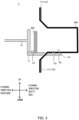
- FIG. 3 is a diagram illustrating a positional relationship between the attaching part 11 and the first guide part 17 in the third embodiment.
- FIG. 3 illustrates a cross section of the sheet storing device 1 in the plane including the up-down direction and the storing direction.
- the first guide part 17 is in contact with the inner surface of the storage bag 600 on the depth side in the storing direction than the attaching part 11.
- the end portion of the first guide part 17 on the depth side in the storing direction is protruded to the depth side than the attaching part 11.
- the recessed portion is also protruded to the depth side than the attaching part 11.
- the second guide part 18 is disposed on the depth side in the storing direction than the first guide part 17, and therefore the end portion of the second guide part 18 on the near side in the storing direction is also located on the depth side than the attaching part 11 because the end portion of the first guide part 17 on the depth side is protruded to the depth side than the attaching part 11.
- a first attaching part 11D of the pair of attaching parts 11 is disposed on the lower side of the first guide part 17 and the second guide part 18.
- a second attaching part 11U is located on the upper side of the first guide part 17 and the second guide part 18.
- the storage bag 600 attached to the first attaching part 11D obliquely extends from the upper end portion of the first attaching part 11D to the end portion of the second guide part 18 on the near side in the storing direction, and then extends to the depth side in the storing direction along the second flat surface of the second guide part 18.
- the end portion of the first guide part 17 on the depth side in the storing direction makes contact with the inner surface of the storage bag 600 by covering the obliquely extending storage bag 600 from the upper side. Note that in FIG.
- a gap between the end portion of the first guide part 17 on the depth side and the storage bag 600 is illustrated for the sake of convenience of illustration, but practically the end portion of the first guide part 17 on the depth side and the storage bag 600 are in contact with each other as described above.
- end portion of the first guide part 17 on the depth side in the storing direction and the end portion of the second guide part 18 on the near side in the storing direction may be formed in oblique cross-sectional shapes matching the obliquely extending storage bag 600 as illustrated in FIG. 3 .
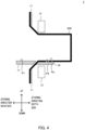
- a pair of the sealing parts 13 is provided on the depth side in the storing direction than the attaching part 11.
- the pair of sealing parts 13 is disposed at a position that sandwiches, from the outside, the storage bag 600 attached to the attaching part 11.
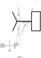
- FIG. 5 is a diagram illustrating a state where the storage bag 600 is closed by the sealing part 13.
- FIG. 5 illustrates a state of the sealing part 13 and the storage bag in the plane including the up-down direction and the storing direction. Note that in the example illustrated in FIGS.
- the sealing part 13 moves along the up-down direction such that the positions in the storing direction is not changed before and after the movement, but the positions in the storing direction may be changed before and after the movement.
- the pair of sealing parts 13 is provided, but the sealing part 13 do not necessarily have to be a pair.
- a single sealing part disposed on the upper side of the storage bag 600 may move downward to a position that sets the opening of the storage bag 600 to the closed state.
- the sealing part 13 is disposed at a position overlapping the second guide part 18 in the storing direction before sandwiching the storage bag 600.
- the second guide part 18 moves to the depth side in the storing direction as illustrated in FIG. 5 , to move out to the position where it does not hinder the movement of the sealing part 13.
- the second guide part 18 may move to the depth side in the storing direction, and to the upper side. In this case, the second guide part 18 moves in the direction of closing the storage bag 600, and thus can serve an auxiliary role of closing the storage bag 600.
- a known method may be adopted for the method of sealing the storage bag 600 with the sealing part 13.
- the sealing part 13 is a heater, and seals the storage bag 600 by applying heat.
- the sealing part 13 may seal the storage bag 600 by bonding the inlet of the storage bag 600 through application of a pressure, or may seal the storage bag 600 by using a device such as a stapler.
- FIG. 6 is a diagram for describing a configuration on the near side in the storing direction than the first guide part 17 in the fifth embodiment.
- a temporary retainer 25 for temporarily retaining the sheet 500 to be stored in the storage bag 600 is provided on the near side in the storing direction than the first guide part 17.
- the moving part 21 is configured to be movable from the near side in the storing direction than the temporary retainer 25, to the inside of the storage bag 600, which is the depth side.
- the temporary retainer 25 and the first guide part 17 may be separated from each other along the storing direction, for example.
- the temporary retainer 25 and the first guide part 17 may move in the direction away from each other, for example.
- the first guide part 17 and the second guide part 18 may separate.
- the storage bag 600 is disposed between the first guide part 17 and the second guide part 18, and then the first guide part 17 is returned to the original position, and thus the storage bag 600 is sandwiched by the first guide part 17 and the second guide part 18, for example.
- the upper surface of the temporary retainer 25 is a third flat surface P3 that is located on the same plane as the first flat surface P1 of the first guide part 17.
- the accumulated sheets 500 before moved to the storage bag 600 make contact with the third flat surface P3.
- the temporary retainer 25 is in contact with the first guide part 17, and the shapes of the terminal end of the third flat surface P3 making up the end portion of the temporary retainer 25 and the starting end of the first flat surface P1 making up the end portion of the first guide part 17 have uneven shapes that engage with each other.
- FIG. 6 a gap between the end portion of the temporary retainer 25 and the end portion of the first guide part 17 is illustrated, but practically the end portion of the temporary retainer 25 and the end portion of the first guide part 17 are in contact with each other.
- FIG. 7 is a top view illustrating an end portion E3 of the temporary retainer 25 on the depth side in the storing direction and an end portion E4 of the first guide part 17 on the near side in the storing direction in the fifth embodiment. Note that in FIGS. 6 and 7 , a gap between the end portion of the temporary retainer 25 and the end portion of the first guide part 17 is illustrated, but practically the end portion of the temporary retainer 25 and the end portion of the first guide part 17 are in contact with each other.
- a protruding tip end portion EP3 of the end portion E3 of the temporary retainer 25 is located on the depth side in the storing direction than a protruding tip end portion EP4 of the end portion E4 of the first guide part 17. Therefore, when the portion where the temporary retainer 25 and the first guide part 17 are in contact with each other with the storage bag 600 therebetween is viewed from the left or right side, the temporary retainer 25 and the first guide part 17 overlap each other.
- the width of the unevenness of each of the temporary retainer 25 and the first guide part 17 in the left-right direction is sufficiently smaller than the length of one end portion of the sheet 500 (see FIG. 1 ). In this manner, when the sheet 500 moves from the terminal end of the third flat surface P3 to the starting end of the first flat surface P1, it can be prevented from being caught, fallen or the like between the terminal end of the third flat surface P3 and the starting end of the first flat surface P1.
- the unevenness of the end portion E3 of the temporary retainer 25 and the end portion E4 of the first guide part 17 is edgeless unevenness. In this manner, when the sheet 500 in the standing state moves from the terminal end of the third flat surface P3 to the starting end of the first flat surface P1, it can be further effectively prevented from being caught, fallen or the like between the terminal end of the third flat surface P3 and the starting end of the first flat surface P1.
- a restriction part 23 that restricts the movement of the sheet 500 from the temporary retainer 25 to the inside of the storage bag 600 is provided on the depth side in the storing direction than the temporary retainer 25.
- FIG. 8 is a diagram illustrating an example of a configuration of the sheet storing device 1 according to the sixth embodiment.
- the restriction parts 23 are paired in the up-down direction, for example.
- the pair of the restriction parts 23 can be opened and closed in the up-down direction.
- the restriction part 23 supports the sheet 500 stored in the storage bag 600 between it and a stage 15 described later such that the sheet 500 stored in the storage bag 600 is not fallen over to the near side in the storing direction.
- the restriction part 23 in the closed state restricts the movement of the sheet 500 from the temporary retainer 25 to the inside of the storage bag 600
- the restriction part 23 in the opened state allows for the movement of the sheet 500 from the temporary retainer 25 to the inside of the storage bag 600.
- restriction parts 23 are paired in the up-down direction in FIG. 8 , the restriction part 23 may not be a pair. A single restriction part, or three or more restriction parts may be provided.
- the stage 15 will be elaborated in the eighth embodiment with reference to FIG. 11 and the like.
- a feeding part 24 performs accumulation of the sheets 500 at the temporary retainer 25.
- the feeding part 24 feeds, into a moving unit 20, the sheet 500 transported from the outside of the sheet storing device 1.
- the feeding part 24 feeds, into the moving unit 20, the sheet 500 with momentum toward the depth side in the storing direction.
- the sheet 500 fed by the feeding part 24 is supported in the standing state by the surface of the closed restriction part 23 on the near side in the storing direction to lean on it.
- the sheets 500 are stacked and temporarily retained at the temporary retainer 25.
- the sheet storing device 1 comprises a control part 50.
- the control part 50 controls the moving operation of the sheet 500 with the moving part 21, the restriction operation of the sheet 500 with the restriction part 23, and the feeding operation with the feeding part 24.
- the control part 50 is a processor such as a CPU (central processing part).
- the control part 50 controls the moving operation of the moving part 21, the restriction operation of the restriction part 23, or the feeding operation of the feeding part 24 by controlling a driving part such as a motor that supplies the driving force for moving the moving part 21, the restriction part 23, and the feeding part 24.
- the control part 50 moves the moving part 21 to the depth side in the storing direction on the basis of the number of the sheets 500 accumulated inside the temporary retainer 25 in the state where the restriction part 23 restricts the movement of the sheet 500.
- the movement amount of the moving part 21 moved by the control part 50 may be determined based on the sum of the thicknesses of the sheets 500 retained inside the temporary retainer 25, for example.
- the control part 50 may specify the number of the sheets 500 retained inside the temporary retainer 25 on the basis of the number of sheets fed by the feeding part 24.
- the moving part 21 is provided with a protrusion extending downward, and the second guide part 18 is provided with a groove for passing through the protrusion.
- the sheet storing device 1 can reduce the falling over of the sheet 500, but it is difficult to eliminate the fallen sheet 500 when the sheet 500 are fallen over.
- the fallen sheet 500 is sandwiched by the inlet portion when sealing the inlet of the storage bag 600 with the sealing part 13, it is difficult to seal the inlet, and therefore a configuration for immediately eliminating the fallen sheet 500 is desired.
- FIG. 9 is a diagram for describing a protrusion 211 extending downward from the moving part 21 and a groove 181 provided in the second guide part 18 in the seventh embodiment.
- FIG. 9 is a sectional view of a second guide part of the sheet storing device 1 taken along a plane including the up-down direction and the left-right direction.
- the tip end of the protrusion 211 is located inside the groove 181.
- the storage bag 600 held by the second guide part 18 is pushed by the protrusion 211 and protruded downward as illustrated in FIG. 9 .
- the width of the groove 181 in the left and right direction is smaller than the width of the sheet 500, and the tip end of the protrusion 211 and the inner surface of the storage bag 600 are in contact with each other at the groove 181, and thus, even if there is a fallen sheet 500, it cannot enter the portion between the protrusion 211 and the storage bag 600.
- the fallen sheet 500 is pushed by the protrusion 211 to the depth side or near side in the storing direction as the moving part 21 moves. In this manner, it is possible to prevent a situation where the fallen sheet 500 is sandwiched by the inlet of the storage bag 600 when sealing the storage bag 600, making it difficult to seal the inlet.
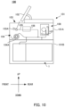
- a sheet processing device 100 comprising the sheet storing device 1 of the above-described embodiments is described.
- the sheet processing device 100 is an apparatus comprising a processing part that performs each mechanism in the apparatus to perform various processes such as sheet depositing process or dispensing process.
- the side of the sheet processing device 100 on which a reception part 103 described later is disposed is the front side, and the side opposite to the front side is the rear side.
- the left-right direction orthogonal to the front-rear direction is the left-right direction.
- the sheet processing device 100 comprises a housing 101 with a substantially cuboid shape.
- An upper unit 101A and a lower unit 101B are housed inside the housing 101.
- An operation part 102 is provided at the upper part of the housing 101.
- the operation part 102 receives an operation of the user of the sheet processing device 100.
- the sheet processing device 100 performs various processes in accordance with the user's operation on the operation part 102.
- the operation part 102 may be a touch panel laid on a display such as a liquid crystal display, for example.
- the display displays a screen for the user to select the process to be performed by the sheet processing device 100, a screen indicating the amount (number of sheets or total amount) of the sheets 500 stored in the sheet processing device 100 or the like.
- the reception part 103 is provided at an upper part of the front surface of the housing 101.
- the reception part 103 comprises a reception hopper for inserting banknotes into the housing 101 from the outside, and the like.
- the dispensing part 104 for dispensing banknotes from the inside of the housing 101 to the outside is provided on the lower side of the reception part 103.
- the reception part 103 receives a sheet group composed of one or more sheets set by the user.
- the reception part 103 is provided with a feeding mechanism 103A for feeding the sheets of the sheet group one by one into the housing 101.
- the sheets fed from the feeding mechanism 103A one by one is transported by the transport part 105 one by one.
- the recognition part 106 is provided on the transport path making up the transport part 105.
- the recognition part 106 recognizes the denomination, authentication, front/rear, fitness, new/old, transport state and the like of the sheets transported by the transport part 105.
- the storage feeding part 107 (temporary retainer) is provided at the succeeding stage of the recognition part 106 in the transport part 105.
- the storage feeding part 107 temporarily stores sheets transported from the transport part 105, and feeds the stored sheets one by one to the transport part 105. In this manner, the banknotes stored in the storage feeding part 107 can be transported from the storage feeding part 107 to the sheet storing device 1 provided in the lower unit 101B.
- the storage feeding part 107 is composed of a feeding part of a tape-reel type, for example.
- the dispensing part 104 is connected to the transport part 105. In the dispensing process of the sheet processing device 100 and the like, the required number of sheets is temporarily accumulated at the dispensing part 104 by the transport part 105.
- the dispensing part 104 is accessible from the outside of the housing 101, and the user can take out the sheets accumulated at the dispensing part 104 from the front surface of the housing 101.
- a stacking wheel 104A is provided at the connection portion with the dispensing part 104 at the transport part 105. Through the rotation of the stacking wheel 104A, the sheet sandwiched by the vane of the stacking wheel 104A is accumulated at the dispensing part 104.
- the processing part 108 with the configurations described above performs various processes such as a depositing process and a dispensing process on sheets received from the reception part 103.
- the depositing process is a process of storing the received sheets into the storage feeding part 107 or the sheet storing device 1
- the dispensing process is a process of dispensing sheets from the storage feeding part 107 to the dispensing part 104.
- FIG. 11 is a diagram illustrating a general configuration of the sheet storing device 1.
- the storage bag 600 such as a pouch bag is laterally attached, and sheets are stacked and stored in a standing state.
- the standing state of the sheets is a state where the front and rear surfaces of the sheet face the direction perpendicular to the up-down direction.
- the sheet storing device 1 comprises an attaching unit 10, the moving unit 20, the sliding part 30, and the control part 50.
- the inlet of the storage bag 600 is attached to face the front side of the sheet processing device 100, but the present disclosure is not limited to this, and the inlet of the storage bag 600 may face the left side, right side or rear side of the sheet processing device 100, or the direction perpendicular to the up-down direction.
- the right side in FIG. 11 is the front side of the sheet storing device 1
- the left side in FIG. 11 is the rear side of the sheet storing device 1.
- the direction from the front side to the rear side of the sheet storing device 1 is the same direction as the storing direction in the above-described embodiments.
- the attaching unit 10 is a unit to which the storage bag 600 is attached.
- the moving unit 20 is a unit that moves the sheet 500 transported by the transport part 105 along the storing direction with the sheet kept in the standing state, and stores the sheet in the storage bag 600.
- the attaching unit 10 comprises the attaching part 11, a closing part 12 and the sealing part 13. Further, the attaching unit 10 comprises the stage 15 and a lid 16 as illustrated in FIG. 11 . Note that the first guide part 17 and the second guide part 18 in the above-described first to seventh embodiments are configurations provided in the attaching unit 10.
- the stage 15 that is movable along the storing direction is provided inside the attaching unit 10.
- the stage 15 is a portion that regulates the depth from the inlet to the bottom of the laterally attached storage bag 600.
- the stage 15 is moved by the driving force supplied by a driving part under the control of the control part 50, for example.
- a gap is provided near the center of the stage 15 in the left-right direction or the up-down direction. Through this gap, a part of the storage bag 600 can be extended to the depth side in the storing direction. In this manner, the number of the sheets 500 that can be stored in the storage bag 600 can be regulated by moving the stage 15. In FIG. 11 , the gap of the stage 15 is provided near the center in the up-down direction.
- An opening is provided at the top surface of the attaching unit 10.
- This opening is provided with the openable and closable lid 16.
- the lid 16 can be opened and closed through a hinge, and is opened and closed by the hand of the user of the sheet processing device 100, for example.
- the lid 16 is in a closed state.
- the attaching unit 10 can be pulled out of the housing 101 by means of the sliding part 30, and when the attaching unit 10 is pulled out of the housing 101, the user can easily access the inside of the sheet storing device 1, especially the attaching part 11, by opening the lid 16. In this manner, the user can easily attach the storage bag 600 to the attaching unit 10.
- the moving unit 20 comprises the moving part 21, a holding part 22, the restriction part 23 and the feeding part 24.
- the moving unit 20 is disposed next to the attaching unit 10 on the near side of the attaching unit 10 in the storing direction, i.e., the side on which the attaching part 11 is disposed.
- the moving part 21, the holding part 22 and the restriction part 23 move with a driving force supplied by a driving part under the control of the control part 50.
- a single driving part may supply the driving force to the moving part 21, the holding part 22 and the restriction part 23, or respective driving parts may supply the driving force to them.
- the moving part 21 moves the sheets 500 supplied from the outside of the moving unit 20 by pushing the sheets 500 from the inside of the moving unit 20 to the inside of the storage bag 600 attached to the attaching unit 10.
- the moving part 21 can move along the storing direction from the near side to the depth side in the storing direction, or from the depth side to the near side in the storing direction.
- the sheet 500 is pushed into the storage bag 600 by the tip end portion of the moving part 21 on the side closer to the attaching unit 10.
- the sheet 500 kept in the standing state, is pushed by the moving part 21.
- the tip end portion of the moving part 21 on the side closer to the attaching unit 10 is simply referred to as tip end portion of the moving part 21.
- the sheet 500 kept in the standing state is stacked and stored in the storage bag 600.
- the moving part 21 is returned to the initial position inside the moving unit 20.
- the initial position of the moving part 21 is a position on the nearest side in the storing direction in the movable region of the moving part 21, i.e., a position where the moving part 21 is farthest away from the attaching unit 10, for example.
- the tip end portion of the moving part 21 is formed in a shape that can efficiently push the sheet 500 in the standing state.
- the shape of the tip end portion of the moving part 21 is specifically described later.
- a gap for disposing the holding part 22 is provided near the center of the moving part 21 in the up-down direction.
- the holding part 22 is a plate-shaped or rod-shaped portion for holding the sheet 500 pushed by the moving part 21 into the storage bag 600.
- the holding part 22 is disposed inside the gap provided near the center of the moving part 21 in the up-down direction. Through this gap, the holding part 22 can move along the storing direction.
- the moving part 21 and the holding part 22 are not fixed to each other, and can move independently of each other along the storing direction.
- the restriction part 23 is a member provided near the boundary between the moving unit 20 and the attaching unit 10 to restrict the movement into the storage bag 600 of the sheet 500 inside the moving unit 20.
- the restriction part 23 supports the banknote stored in the storage bag 600 between it and the stage.
- the restriction part 23 prevents unintentional entry of the sheet 500 into the storage bag 600 by restricting the movement of the sheet 500.
- the restriction part 23 releases the restriction.
- the restriction part 23 has a structure divided in the up-down direction.
- the upper portion of the restriction part 23 is configured to move upward, and the lower portion of the restriction part 23 is configured to move downward. In this manner, the restriction part 23 can be opened and closed.
- FIG. 11 illustrates the position of the restriction part 23 in the closed state with the solid line, and the position of the restriction part 23 in the opened state with the broken line.
- FIG. 12 is a diagram illustrating the moving part 21, the holding part 22, and the restriction part 23 as viewed from the depth side in the storing direction.
- the restriction part 23 is divided in the up-down direction, and each piece is formed in a comb-tooth shape.
- FIG. 12 illustrates the restriction part 23 in the closed state.
- the restriction part 23 in the closed state can be set to restrict the movement of the sheet 500 to the depth side in the storing direction.
- the restriction part 23 in the opened state can be set to not restrict the movement of the sheet 500 to the depth side in the storing direction.
- the tip end portion of the moving part 21 on the depth side in the storing direction is formed in a shape that can pass through the gap of the comb-tooth shape of the restriction part 23 in the closed state.
- the tip end portion of the moving part 21 is formed in a shape with a large area in the plane perpendicular to the up-down direction and the storing direction.
- the moving part 21 can efficiently push the sheet 500 in the standing state.
- the feeding part 24 is a portion that feeds, into the moving unit 20, the sheet 500 transported by the transport part 105.
- the feeding part 24 performs the feeding operation under the control of the control part 50.
- the feeding part 24 comprises a rotatable vane to feed the sheet 500 toward the depth side in the storing direction with momentum into the moving unit 20, for example. In this manner, the sheets 500 fed by the feeding part 24 are stacked in the standing state on the near side of the restriction part 23 in the closed state in the storing direction.
- the sliding part 30 is a portion for sliding the attaching unit 10 to the outside of the housing 101 of the sheet processing device 100. Openable and closable doors are provided at the front, rear, left and right wall surfaces of the lower unit 101B, and the user can pull the attaching unit 10 to the outside of the housing 101 from the opened door by means of the sliding part 30. In this manner, the user can easily attach or detach the storage bag 600 to or from the attaching unit 10.
- the sliding part 30 is a slide rail member, for example. In the example illustrated in FIG. 10 , the sliding part 30 is provided along the front-rear direction, and the attaching unit 10 can be pulled out from the door provided on the front side or rear side of the housing 101. Note that the sliding part 30 may be configured to slide the moving unit 20 together with the attaching unit 10. In this case, a sliding part for sliding the attaching unit 10 and a sliding part for moving the moving unit 20 may be separately provided.
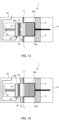
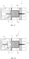
- FIGS. 13 to 18 are diagrams illustrating each step of an operation of the sheet storing device 1 of storing a predetermined number of sheets into the storage bag 600.
- illustration of the closing part 12 and the sealing part 13, which are not described, is omitted.
- a predetermined number of sheets 500 are fed by the feeding part 24 on the temporary retainer 25 of the moving unit 20, and retained so as to lean on the restriction part 23 (step S1). Note that in the example illustrated in FIG. 13 , a certain number of the sheets 500 is stored in advance in the storage bag 600, and the stage 15 of the attaching unit 10 has been moved to a position corresponding to the number of the stored sheets 500.
- step S2 when a predetermined number of sheets 500 is retained, the restriction part 23 is opened (step S2).
- the moving part 21 moves the sheet 500 into the storage bag 600 by pushing the sheet 500 toward the depth side in the storing direction (step S3).
- the sheet 500 retained to lean on the restriction part 23 is temporarily held by the sheet 500 stored in advance in the storage bag 600, so as not to fallen over.
- the sheet 500 can be prevented from being fallen over even when the restriction part 23 is opened by moving the stage 15 to the nearest side in the storing direction.
- FIG. 16 illustrates a state where the tip end portion of the moving part 21 has been reached a storage position. Note that when the tip end portion of the moving part 21 cannot reach the storage position due to the thickness of the sheet 500 stored in the storage bag 600, the tip end portion of the moving part 21 is set to the storage position by moving the stage 15 to the depth side in the storing direction as illustrated in FIG. 16 (step S4).
- the driving force for moving the moving part 21 to the depth side in the storing direction is continuously supplied.
- the sheet 500 is compressed by the moving part 21 in the storage bag 600.
- the predetermined storage position is a position slightly on the depth side in the storing direction than the restriction part 23, for example.
- step S5 After the position of the tip end portion of the moving part 21 in the storing direction is set to a predetermined storage position, the supply of the driving force to the moving part 21 is stopped, and the position of the moving part 21 in the storing direction is fixed. In this state, the restriction part 23 is closed as illustrated in FIG. 17 (step S5).
- step S6 the entire moving part 21 is returned toward the near side in the storing direction through the gap of the restriction part 23.
- the sheet 500 with no compression force of the moving part 21 acts to return to the near side in the storing direction in the storage bag 600, but it cannot return to the inside of the moving unit 20 due to the restriction part 23.
- the storing of sheets into the storage bag 600 is completed.
- FIGS. 19 to 25 are diagrams illustrating each step of an operation of the sheet storing device 1 of sealing the storage bag 600 in the state where a predetermined number of sheets 500 are stored in the storage bag 600.
- FIG. 19 illustrates a state where a predetermined number of sheets 500 are stored in the storage bag 600 (step S 11).
- the moving part 21 and the holding part 22 move as one piece toward the depth side in the storing direction with the restriction part 23 kept closed (step S12). In this manner, the sheet 500 stored in the storage bag 600 is compressed by the moving part 21 and the stage 15.
- FIG. 21 is a diagram illustrating a state where the tip end portion of the moving part 21 has reached the sealing position.
- the predetermined sealing position is a position on the depth side in the storing direction than the sealing part 13 and the closing part 12.
- the tip end portion of the moving part 21 When the tip end portion of the moving part 21 has reached the sealing position, the tip end portion of the holding part 22 is fixed to the sealing position as illustrated in FIG. 22 , and the entire moving part 21 is returned to the inside of the moving unit 20 (step S14). In this manner, the sheet 500 is held by the holding part 22.
- the moving part 21 may return to the initial position of the moving part 21, or stop as necessary at a position on the depth side in the storing direction in the moving unit 20.
- the closing part 12 closes the storage bag 600 in the state where the holding part 22 holds the sheet 500 (step S15).
- the entire holding part 22 is returned to the inside of the moving unit 20 (step S16). Since the holding part 22 is returned with the storage bag 600 closed to a certain degree, the sheet 500 is held by the inner surface of the storage bag 600 instead of the holding part 22. In this manner, the sheet 500 is not fallen over.
- the moving part 21 and the holding part 22 are returned to the initial position, i.e., the position on the nearest side in the storing direction in the movable region of the moving part 21 and the holding part 22.
- the closing part 12 completely closes the storage bag 600, and the sealing part 13 seals the inlet of the storage bag 600 (step S17). In this manner, the sealing of the storage bag 600 is completed.
- the user pulls the attaching unit 10 to the outside of the housing 101 by means of the sliding part 30 illustrated in FIG. 12 . In this manner, the user can detach from the attaching unit 10 the sealed storage bag 600 in which the sheet 500 is stored, and can attach a new storage bag 600 to the attaching unit 10.
Landscapes
- Engineering & Computer Science (AREA)
- Mechanical Engineering (AREA)
- Physics & Mathematics (AREA)
- General Physics & Mathematics (AREA)
- Bag Frames (AREA)
- Pile Receivers (AREA)
Abstract
Description
- The present disclosure relates to a sheet storing device for storing sheets, and a sheet processing device comprising the sheet storing device.
- Sheet storing devices for storing sheets such as valuable securities or banknotes are widely used. PTL 1 discloses a device that sends banknotes into a laterally disposed bag, and stacks the banknotes in a standing state in the bag, for example.
-
PTL 1
United States Patent No. 9114952 - With the technique disclosed in
PTL 1, a step between a support element for temporarily holding banknotes before sent into a bag and the inner surface of the bag in a sheet storing device, and therefore the banknotes may be caught by the step when being sent into the bag, and as a result the banknotes may be bent, or may remain at the step. - In view of this an object of the present disclosure is to provide a sheet storing device and a sheet processing device that can prevent the sheet from being caught when moving and storing the sheet.
- A sheet storing device of the present disclosure includes: an attaching part configured to attach a storage bag for a sheet; a moving part configured to move the sheet toward inside of the storage bag; a first guide part configured to make contact with an inner surface of the storage bag; and a second guide part configured to make contact with an outer surface of the storage bag, and sandwich the storage bag together with the first guide part. The first guide part comprises a first flat surface configured to make contact with the sheet moved by the moving part. The second guide part comprises a second flat surface configured to make contact with the outer surface of the storage bag such that the sheet moved by the moving part makes contact with a part of the inner surface of the storage bag. The first guide part and the second guide part are disposed such that the first flat surface and the second flat surface are located on the same plane.
- In the sheet storing device of the present disclosure, the end portion of the first guide part and the end portion of the second guide part sandwiching the storage bag may be formed in uneven shapes that engage with each other.
- In the sheet storing device of the present disclosure, the end portion of the first guide part and the end portion of the second guide part sandwiching the storage bag may be formed in edgeless uneven shapes.
- In the sheet storing device of the present disclosure, the width of the unevenness in the left-right direction formed in the end portion of the first guide part and the end portion of second guide part may be smaller than a length of one end portion of the sheet.
- In the sheet storing device of the present disclosure, the end portion of the first guide part may make contact with the inner surface on a depth side than the attaching part in a storing direction in the storage bag to sandwich the storage bag together with the second guide part.
- In the sheet storing device of the present disclosure, the attaching part may comprise a first attaching part and a second attaching part, the first attaching part may be disposed on the lower side than the first guide part and the second guide part, and the second attaching part may be disposed on the upper side than the first guide part and the second guide part.
- In the sheet storing device of the present disclosure, a sealing part configured to close and seal the opening of the storage bag may be further provided.
- In the sheet storing device of the present disclosure, the sealing part may be provided on the depth side than the attaching part in the storing direction at a position sandwiching the storage bag attached to the attaching part from the outside.
- In the sheet storing device of the present disclosure, the sealing part may be configured to close the opening by moving in a direction orthogonal to a direction in which the moving part moves the sheet; and the first guide part may be disposed at a position where no interference with a movement of the sealing part occurs.
- In the sheet storing device of the present disclosure, the second guide part may move to a position where no interference with a movement of the sealing part along with a movement of the sealing part.
- In the sheet storing device of the present disclosure, the sealing part may be disposed at a position overlapping the second guide part in the storing direction before sandwiching the storage bag, and the second guide part may move to the depth side in the storing direction to move out to a position that does not hinder the movement of the sealing part when the sealing part sandwiches the storage bag. In addition, when the second guide part moves to the depth side in the storing direction, it may move upward.
- In the sheet storing device of the present disclosure, a temporary retainer that accumulates the sheet before moved to the storage bag may be further provided.
- The temporary retainer may comprise a third flat surface that makes contact with the accumulated sheet before moved to the storage bag, and the third flat surface may be disposed on the same plane as the first flat surface.
- In the sheet storing device of the present disclosure, the temporary retainer may be in contact with the first guide part; and an end portion of the temporary retainer in contact with the first guide part and an end portion of the first guide part in contact with the temporary retainer may be formed in uneven shapes that engage with each other.
- In the sheet storing device of the present disclosure, the width the unevenness in the left-right direction formed in the end portion of the temporary retainer and the end portion of the first guide part that makes contact with the temporary retainer may be smaller than the length of one end portion of the sheet.
- In the sheet storing device of the present disclosure, the end portion of the temporary retainer in contact with the first guide part and the end portion of the first guide part in contact with the temporary retainer are formed in edgeless uneven shapes.
- In the sheet storing device of the present disclosure, the moving part may be configured to be movable from the near side than the temporary retainer in the storing direction, to the inside of the storage bag, which is the depth side.
- The sheet storing device of the present disclosure further comprises a temporary retainer configured to accumulate the sheet before moved to the storage bag; a restriction part configured to restrict a movement of the sheet between the temporary retainer and the storage bag; and a control part configured to control the moving part and the restriction part. The control part moves the moving part in a direction in which the moving part moves the sheet based on in accordance with the number of the sheet accumulated at the temporary retainer in a state where the restriction part restricts the movement of the sheet. The control part moves the moving part into the storage bag in a state where the restriction part does not restrict the movement of the sheet.
- In the sheet storing device of the present disclosure, the restriction part in the closed state may restrict the movement of the sheet with the moving part from the temporary retainer to the inside of the storage bag, and the restriction part in the opened state may allow for the movement of the sheet with the moving part from the temporary retainer to the inside of the storage bag.
- In the sheet storing device of the present disclosure, the restriction part may be provided as a pair paired in the up-down direction, and the pair of restriction parts may be opened and closed in the up-down direction with control part.
- In the sheet storing device of the present disclosure, the second guide part may comprise a groove formed in the second flat surface along a direction in which the moving part may be the sheet; and the moving part may comprise a protrusion that moves along the groove.
- In the sheet storing device of the present disclosure, the attaching part may attach the storage bag such that a storing direction is horizontal; and the moving part may move the sheet such that the sheet is stored and arranged in a standing posture in the storage bag.
- The sheet storing device of the present disclosure may comprise an attaching part configured to attach a storage bag for a sheet; a moving part configured to move the sheet toward inside of the storage bag; a first guide part configured to make contact with an inner surface of the storage bag; and a second guide part configured to make contact with an outer surface of the storage bag, and sandwich the storage bag together with the first guide part, the first guide part comprises a first flat surface making up a part of a guide surface configured to make contact with the sheet moved by the moving part, the second guide part comprises a second flat surface configured to bring a part of the inner surface of the storage bag into contact with a part of the guide surface by making contact with the outer surface of the storage bag, and the first guide part and the second guide part are disposed such that there is no step at the guide surface.
- The sheet processing device of the present disclosure comprises a reception part configured to receive a sheet and the above-mentioned sheet storing device configured to store the sheet.
- According to the present disclosure, the sheet can be prevented from being caught when moving and storing the sheet.
-
-
FIG. 1 is a diagram for describing a configuration of a sheet storing device of a first embodiment of the present disclosure; -
FIG. 2 is a top view illustrating an end portion E1 of a first guide part on the depth side in the storing direction, and an end portion E2 of a second guide part on the near side in the storing direction in a second embodiment; -
FIG. 3 is a diagram illustrating a positional relationship between an attaching part and a first guide part in a third embodiment; -
FIG. 4 is a diagram for describing a sheet processing device comprising a sealing part in a fourth embodiment; -
FIG. 5 is a diagram illustrating a state where a storage bag is closed with the sealing part in the fourth embodiment; -
FIG. 6 is a diagram for describing a configuration on the near side in the storing direction than a first guide part in a fifth embodiment; -
FIG. 7 is a top view illustrating an end portion E3 of a temporary retainer on the depth side in the storing direction, and an end portion E4 of the first guide part on the near side in the storing direction in the fifth embodiment; -
FIG. 8 is a diagram illustrating an example of a configuration of a sheet storing device according to a sixth embodiment; -
FIG. 9 is a diagram for describing a protrusion extending downward from a moving part, and a groove provided in a second guide part in a seventh embodiment; -
FIG. 10 is a diagram for describing a configuration of a sheet processing device in an eighth embodiment; -
FIG. 11 is a diagram for describing a configuration of a sheet storing device in the eighth embodiment; -
FIG. 12 is a diagram for describing an exemplary operation for storing a sheet in the sheet storing device in the eighth embodiment; -
FIG. 13 is a diagram for describing an exemplary operation for storing a sheet in the sheet storing device in the eighth embodiment; -
FIG. 14 is a diagram for describing an exemplary operation for storing a sheet in the sheet storing device in the eighth embodiment; -
FIG. 15 is a diagram for describing an exemplary operation for storing a sheet in the sheet storing device in the eighth embodiment; -
FIG. 16 is a diagram for describing an exemplary operation for storing a sheet in the sheet storing device in the eighth embodiment; -
FIG. 17 is a diagram for describing an exemplary operation for storing a sheet in the sheet storing device in the eighth embodiment; -
FIG. 18 is a diagram for describing an exemplary operation for sealing a storage bag of the sheet storing device in the eighth embodiment; -
FIG. 19 is a diagram for describing an exemplary operation for sealing the storage bag of the sheet storing device in the eighth embodiment; -
FIG. 20 is a diagram for describing an exemplary operation for sealing the storage bag of the sheet storing device in the eighth embodiment; -
FIG. 21 is a diagram for describing an exemplary operation for sealing the storage bag of the sheet storing device in the eighth embodiment; -
FIG. 22 is a diagram for describing an exemplary operation for sealing the storage bag of the sheet storing device in the eighth embodiment; -
FIG. 23 is a diagram for describing an exemplary operation for sealing the storage bag of the sheet storing device in the eighth embodiment; -
FIG. 24 is a diagram for describing an exemplary operation for sealing the storage bag of the sheet storing device in the eighth embodiment; and -
FIG. 25 is a diagram for describing an exemplary operation for sealing the storage bag of the sheet storing device in the eighth embodiment. - The following is a detailed description of each embodiment of the present disclosure with reference to the drawings. However, explanations that are more detailed than necessary, for example, detailed explanations of already well-known matters or duplicated explanations of substantially identical configurations, etc., may be omitted. In addition, the same symbols may be attached to configurations that are common to each embodiment, and duplicate explanations may be omitted.
-
FIG. 1 is a diagram for describing a configuration of a sheet storing device of the first embodiment of the present disclosure. As illustrated inFIG. 1 , asheet storing device 1 comprises an attachingpart 11, a movingpart 21, afirst guide part 17, and asecond guide part 18. - The attaching
part 11 attaches astorage bag 600 for storing asheet 500. For example, in the present embodiment, thestorage bag 600 is attached to the attachingpart 11 with the inlet open. Thesheet 500 is a banknote, a security or the like. Note that whileFIG. 1 illustrates an example where a pair of the attachingparts 11 is provided, the attachingpart 11 may not be a pair, and three or more attaching parts may be provided. In addition, the attaching parts may have different shapes. - The moving
part 21 move toward the inside of thestorage bag 600 attached to the attachingpart 11. In this manner, the movingpart 21 pushes thesheet 500 to move it. - The
first guide part 17 and thesecond guide part 18 guide the movement of thesheet 500 moved by the movingpart 21. One or a plurality of thesheets 500 may be stored in thestorage bag 600. - The
storage bag 600 is attached to the attachingpart 11 such that the inlet faces the movingpart 21 side. When the movingpart 21 moves toward the inside of thestorage bag 600 in this state, thesheet 500 is pushed by the movingpart 21 to enter thestorage bag 600 together with the movingpart 21. - In the following description, the direction from one side to the other of the pair of attaching
parts 11 is the first direction. In addition, in the following description, the moving direction of the movingpart 21, i.e., the direction in which thesheet 500 is stored in thestorage bag 600, is referred to as storing direction. In the following description, as viewed from the inlet side of thestorage bag 600, the inner side of the storage bag is referred to as depth side in the storing direction. In addition, the side opposite to the depth side in the storing direction is referred to as near side. The depth side in the storing direction is the right side inFIG. 1 . On the other hand, the near side in the storing direction is the left side inFIG. 1. FIG. 1 is a sectional view of thesheet storing device 1 taken along a plane including the first direction and the storing direction orthogonal to the first direction. - The surfaces of the
first guide part 17 and thesecond guide part 18 that guide thesheet 500 are flat surfaces. Note that a flat surface in this specification comprises flat surfaces with a slight curvature, a slight unevenness, a slight inclination and the like, as well as completely flat surfaces. As illustrated inFIG. 1 , the surface of thefirst guide part 17 that guides thesheet 500 is a first flat surface P1, and the surface of thesecond guide part 18 that guides thesheet 500 is a second flat surface P2. Thefirst guide part 17 and thesecond guide part 18 are disposed with the first flat surface P1 and the second flat surface P2 located on the same plane. Note that in this specification, the same plane includes substantially the same planes, which includes a case where the first flat surface P1 and the second flat surface P2 are shifted from each other by about the thickness of thestorage bag 600, for example. - In addition, the
first guide part 17 and thesecond guide part 18 are disposed so as to sandwich from the inner and outer surfaces thestorage bag 600 attached to the attachingpart 11 as illustrated inFIG. 1 . - With this arrangement, a guide surface for guiding the
sheet 500 when pushing thesheet 500 by the movingpart 21 and storing it into the storage bag is formed. The guide surface is composed of a part Pp of the inner surface of thestorage bag 600 held by the first flat surface P1 of thefirst guide part 17 and the second flat surface P2 of thesecond guide part 18. Note that in the following description, the part Pp of the inner surface of thestorage bag 600 held by the second flat surface P2 of thesecond guide part 18 is simply referred to as inner surface Pp. As described above, thefirst guide part 17 and thesecond guide part 18 are disposed such that the first flat surface P1 and the second flat surface P2 are located on the same plane, and therefore the first flat surface P1 and the inner surface Pp are also located on the same plane even when taking into account the thickness of thestorage bag 600 sandwiched between thefirst guide part 17 and thesecond guide part 18. - When the
sheet 500 is stored in thestorage bag 600, the movingpart 21 moves along the storing direction as described above, and thus it pushes thesheet 500 to the inside of thestorage bag 600. At this time, thesheet 500 is moved by the movingpart 21, with the front surface or rear surface facing the depth side or near side in the storing direction. In this manner, thesheet 500 is stacked and stored in thestorage bag 600. - In the initial stage of the movement of the moving
part 21, thesheet 500 is guided by the first flat surface P1 of thefirst guide part 17. Specifically, in the initial stage of the movement of the movingpart 21, one end surface of thesheet 500 moves in contact with the first flat surface P1. As the movement proceeds, thesheet 500 reaches the terminal end of the first flat surface P1 in the storing direction, and makes contact with the inner surface of thestorage bag 600 held by the second flat surface P2 of thesecond guide part 18. The contact portion at this time is the starting end of the inner surface Pp in the storing direction. Thereafter, thesheet 500 moves with one end surface in contact with the inner surface Pp, which is a part of the inner surface of thestorage bag 600 held by the second flat surface P2. - As described above, the first flat surface P1 and the inner surface Pp are located on the same plane. In this manner, when the
sheet 500 is pushed by the movingpart 21 to move from the terminal end of the first flat surface P1 to the starting end of the inner surface Pp in the storing direction, it can be prevented from being caught, fallen or the like between the terminal end of the first flat surface P1 and the starting end of the inner surface Pp. - In a sheet processing device of a second embodiment, the end portion of the
first guide part 17 making up the terminal end of the first flat surface P1, and the end portion of thesecond guide part 18 making up the starting end of the inner surface Pp when thestorage bag 600 is attached have uneven shapes that engage with each other. - Note that the following description assumes that the
storage bag 600 is attached in a lateral manner with respect to thesheet storing device 1. The lateral manner means a state where the inlet of thestorage bag 600 faces the direction perpendicular to the up-down direction. - The up-down direction in the following description corresponds to the up-down direction of a case where the
sheet storing device 1 is installed on the horizontal plane. The up-down direction of thesheet storing device 1 is a direction orthogonal to the above-described storing direction. -
FIG. 2 is a top view illustrating an end portion E1 of thefirst guide part 17 on the depth side in the storing direction, and an end portion E2 of thesecond guide part 18 on the near side in the storing direction in the second embodiment. In the following description, in thesheet storing device 1, the left side of thesecond guide part 18 as viewed from thefirst guide part 17 is the left side, and the right side of thesecond guide part 18 as viewed from thefirst guide part 17 is the right side. - In
FIG. 2 , a gap between thefirst guide part 17 and thesecond guide part 18 is exaggeratedly illustrated, but practically this gap is about the thickness of the storage bag 600 (seeFIG. 1 ). In this manner, as described in the first embodiment, thefirst guide part 17 and thesecond guide part 18 are in contact with each other with thestorage bag 600 therebetween. - As illustrated in
FIG. 2 , a protruding tip end portion EP1 of the end portion E1 of thefirst guide part 17 is located on the depth side in the storing direction than a protruding tip end portion EP2 of the end portion E2 of thesecond guide part 18. As such, when the portion where thefirst guide part 17 and thesecond guide part 18 are in contact with each other with thestorage bag 600 therebetween is viewed from the left or right side, thefirst guide part 17 and thesecond guide part 18 overlap each other. - Note that the width of the unevenness of each of the
first guide part 17 and thesecond guide part 18 in the left-right direction is sufficiently smaller than the length of the one end portion of the sheet 500 (seeFIG. 1 ). In this manner, when thesheet 500 moves from the terminal end of the first flat surface P1 to the starting end of the inner surface Pp, it can be prevented from being caught, fallen or the like between the terminal end of the first flat surface P1 and the starting end of the inner surface Pp. - Further, as illustrated in
FIG. 2 , the unevenness of each of the end portion E1 of thefirst guide part 17 and the end portion E2 of thesecond guide part 18 is edgeless unevenness. In this manner, when thesheet 500 in the standing state moves from the terminal end of the first flat surface P1 to the starting end of the inner surface Pp, it can be further effectively prevented from being caught, fallen or the like between the terminal end of the first flat surface P1 and the starting end of the inner surface Pp. - In a sheet processing device of a third embodiment, the portion of the
first guide part 17 that makes contact with the inner surface of thestorage bag 600 attached to the attachingpart 11 is located on the depth side in the storing direction than the attachingpart 11. -
FIG. 3 is a diagram illustrating a positional relationship between the attachingpart 11 and thefirst guide part 17 in the third embodiment.FIG. 3 illustrates a cross section of thesheet storing device 1 in the plane including the up-down direction and the storing direction. As illustrated inFIG. 3 , thefirst guide part 17 is in contact with the inner surface of thestorage bag 600 on the depth side in the storing direction than the attachingpart 11. In other words, the end portion of thefirst guide part 17 on the depth side in the storing direction is protruded to the depth side than the attachingpart 11. In the case where the end portion of thefirst guide part 17 on the depth side is formed in an uneven shape as in the second embodiment, the recessed portion is also protruded to the depth side than the attachingpart 11. - The
second guide part 18 is disposed on the depth side in the storing direction than thefirst guide part 17, and therefore the end portion of thesecond guide part 18 on the near side in the storing direction is also located on the depth side than the attachingpart 11 because the end portion of thefirst guide part 17 on the depth side is protruded to the depth side than the attachingpart 11. - On the other hand, as illustrated in
FIG. 3 , a first attachingpart 11D of the pair of attachingparts 11 is disposed on the lower side of thefirst guide part 17 and thesecond guide part 18. In addition, a second attachingpart 11U is located on the upper side of thefirst guide part 17 and thesecond guide part 18. - With this configuration, the
storage bag 600 attached to the first attachingpart 11D obliquely extends from the upper end portion of the first attachingpart 11D to the end portion of thesecond guide part 18 on the near side in the storing direction, and then extends to the depth side in the storing direction along the second flat surface of thesecond guide part 18. The end portion of thefirst guide part 17 on the depth side in the storing direction makes contact with the inner surface of thestorage bag 600 by covering the obliquely extendingstorage bag 600 from the upper side. Note that inFIG. 3 , a gap between the end portion of thefirst guide part 17 on the depth side and thestorage bag 600 is illustrated for the sake of convenience of illustration, but practically the end portion of thefirst guide part 17 on the depth side and thestorage bag 600 are in contact with each other as described above. - Further, the end portion of the
first guide part 17 on the depth side in the storing direction and the end portion of thesecond guide part 18 on the near side in the storing direction may be formed in oblique cross-sectional shapes matching the obliquely extendingstorage bag 600 as illustrated inFIG. 3 . - This reduces the ease of formation of a gap between the end portion of the
first guide part 17 on the depth side in the storing direction, i.e., the terminal end of the first flat surface P1, and the inner surface of thestorage bag 600, i.e., the starting end of the inner surface Pp. In this manner, when thesheet 500 moves from the terminal end of the first flat surface P1 to the starting end of the inner surface Pp, it can be more effectively prevented from being caught, fallen or the like between the terminal end of the first flat surface P1 and the starting end of the inner surface Pp. - In a sheet storing device of a fourth embodiment, a sealing part for closing and sealing the inlet of the storage bag is further provided.
FIG. 4 is a diagram for describing thesheet storing device 1 comprising a sealingpart 13 in the fourth embodiment.FIG. 4 illustrates a cross section of thesheet storing device 1 in the plane including the up-down direction and the storing direction as inFIG. 3 . - In the
sheet storing device 1, a pair of the sealingparts 13 is provided on the depth side in the storing direction than the attachingpart 11. The pair of sealingparts 13 is disposed at a position that sandwiches, from the outside, thestorage bag 600 attached to the attachingpart 11. - The pair of sealing
parts 13 moves along the up-down direction orthogonal to the storing direction after the completion of the movement of the sheet by the movingpart 21, and closes the inlet of thestorage bag 600. When the sealingpart 13 closes the inlet of thestorage bag 600, the sealingpart 13 on the upper side moves downward, and the sealingpart 13 on the lower side moves upward.FIG. 5 is a diagram illustrating a state where thestorage bag 600 is closed by the sealingpart 13.FIG. 5 illustrates a state of the sealingpart 13 and the storage bag in the plane including the up-down direction and the storing direction. Note that in the example illustrated inFIGS. 4 and5 , the sealingpart 13 moves along the up-down direction such that the positions in the storing direction is not changed before and after the movement, but the positions in the storing direction may be changed before and after the movement. In the example illustrated inFIG. 4 , the pair of sealingparts 13 is provided, but the sealingpart 13 do not necessarily have to be a pair. For example, a single sealing part disposed on the upper side of thestorage bag 600 may move downward to a position that sets the opening of thestorage bag 600 to the closed state. - Note that as illustrated in
FIG. 4 , the sealingpart 13 is disposed at a position overlapping thesecond guide part 18 in the storing direction before sandwiching thestorage bag 600. When the sealingpart 13 sandwiches thestorage bag 600, thesecond guide part 18 moves to the depth side in the storing direction as illustrated inFIG. 5 , to move out to the position where it does not hinder the movement of the sealingpart 13. At this time, as illustrated inFIG. 5 , thesecond guide part 18 may move to the depth side in the storing direction, and to the upper side. In this case, thesecond guide part 18 moves in the direction of closing thestorage bag 600, and thus can serve an auxiliary role of closing thestorage bag 600. - A known method may be adopted for the method of sealing the
storage bag 600 with the sealingpart 13. For example, in the case where at least the inner surface of the inlet portion of thestorage bag 600 is formed of resin or the like, the sealingpart 13 is a heater, and seals thestorage bag 600 by applying heat. In addition, the sealingpart 13 may seal thestorage bag 600 by bonding the inlet of thestorage bag 600 through application of a pressure, or may seal thestorage bag 600 by using a device such as a stapler. - In a fifth embodiment, a configuration on the near side in the storing direction than the
first guide part 17 is described. -
FIG. 6 is a diagram for describing a configuration on the near side in the storing direction than thefirst guide part 17 in the fifth embodiment. As illustrated inFIG. 6 , atemporary retainer 25 for temporarily retaining thesheet 500 to be stored in thestorage bag 600 is provided on the near side in the storing direction than thefirst guide part 17. The movingpart 21 is configured to be movable from the near side in the storing direction than thetemporary retainer 25, to the inside of thestorage bag 600, which is the depth side. - Note that in the
sheet storing device 1, when attaching or detaching thestorage bag 600, thetemporary retainer 25 and thefirst guide part 17 may be separated from each other along the storing direction, for example. With a slidingpart 30 described in the eighth embodiment described later, thetemporary retainer 25 and thefirst guide part 17 may move in the direction away from each other, for example. - In addition, when attaching or detaching the
storage bag 600, thefirst guide part 17 and thesecond guide part 18 may separate. At this time, in the state where thefirst guide part 17 is separated from thesecond guide part 18, thestorage bag 600 is disposed between thefirst guide part 17 and thesecond guide part 18, and then thefirst guide part 17 is returned to the original position, and thus thestorage bag 600 is sandwiched by thefirst guide part 17 and thesecond guide part 18, for example. - Now description is returned to
FIG. 6 . The upper surface of thetemporary retainer 25 is a third flat surface P3 that is located on the same plane as the first flat surface P1 of thefirst guide part 17. The accumulatedsheets 500 before moved to thestorage bag 600 make contact with the third flat surface P3. - With the third flat surface P3 of the
temporary retainer 25 located on the same plane as the first flat surface P1, when thesheet 500 retained at thetemporary retainer 25 moves from the terminal end of the third flat surface P3 to the starting end of the first flat surface P1, it can be more effectively prevented from being caught, fallen or the like between the terminal end of the third flat surface P3 and the starting end of the first flat surface P1. - Further, the
temporary retainer 25 is in contact with thefirst guide part 17, and the shapes of the terminal end of the third flat surface P3 making up the end portion of thetemporary retainer 25 and the starting end of the first flat surface P1 making up the end portion of thefirst guide part 17 have uneven shapes that engage with each other. InFIG. 6 , a gap between the end portion of thetemporary retainer 25 and the end portion of thefirst guide part 17 is illustrated, but practically the end portion of thetemporary retainer 25 and the end portion of thefirst guide part 17 are in contact with each other. -
FIG. 7 is a top view illustrating an end portion E3 of thetemporary retainer 25 on the depth side in the storing direction and an end portion E4 of thefirst guide part 17 on the near side in the storing direction in the fifth embodiment. Note that inFIGS. 6 and7 , a gap between the end portion of thetemporary retainer 25 and the end portion of thefirst guide part 17 is illustrated, but practically the end portion of thetemporary retainer 25 and the end portion of thefirst guide part 17 are in contact with each other. - In addition, as illustrated in
FIG. 7 , a protruding tip end portion EP3 of the end portion E3 of thetemporary retainer 25 is located on the depth side in the storing direction than a protruding tip end portion EP4 of the end portion E4 of thefirst guide part 17. Therefore, when the portion where thetemporary retainer 25 and thefirst guide part 17 are in contact with each other with thestorage bag 600 therebetween is viewed from the left or right side, thetemporary retainer 25 and thefirst guide part 17 overlap each other. - Note that the width of the unevenness of each of the
temporary retainer 25 and thefirst guide part 17 in the left-right direction is sufficiently smaller than the length of one end portion of the sheet 500 (seeFIG. 1 ). In this manner, when thesheet 500 moves from the terminal end of the third flat surface P3 to the starting end of the first flat surface P1, it can be prevented from being caught, fallen or the like between the terminal end of the third flat surface P3 and the starting end of the first flat surface P1. - Further, as illustrated in
FIG. 7 , the unevenness of the end portion E3 of thetemporary retainer 25 and the end portion E4 of thefirst guide part 17 is edgeless unevenness. In this manner, when thesheet 500 in the standing state moves from the terminal end of the third flat surface P3 to the starting end of the first flat surface P1, it can be further effectively prevented from being caught, fallen or the like between the terminal end of the third flat surface P3 and the starting end of the first flat surface P1. - In the
sheet storing device 1 according to a sixth embodiment, arestriction part 23 that restricts the movement of thesheet 500 from thetemporary retainer 25 to the inside of thestorage bag 600 is provided on the depth side in the storing direction than thetemporary retainer 25. -
FIG. 8 is a diagram illustrating an example of a configuration of thesheet storing device 1 according to the sixth embodiment. Therestriction parts 23 are paired in the up-down direction, for example. The pair of therestriction parts 23 can be opened and closed in the up-down direction. In the closed state, therestriction part 23 supports thesheet 500 stored in thestorage bag 600 between it and astage 15 described later such that thesheet 500 stored in thestorage bag 600 is not fallen over to the near side in the storing direction. In addition, therestriction part 23 in the closed state restricts the movement of thesheet 500 from thetemporary retainer 25 to the inside of thestorage bag 600, and therestriction part 23 in the opened state allows for the movement of thesheet 500 from thetemporary retainer 25 to the inside of thestorage bag 600. Note that while therestriction parts 23 are paired in the up-down direction inFIG. 8 , therestriction part 23 may not be a pair. A single restriction part, or three or more restriction parts may be provided. In addition, thestage 15 will be elaborated in the eighth embodiment with reference toFIG. 11 and the like. - A feeding
part 24 performs accumulation of thesheets 500 at thetemporary retainer 25. The feedingpart 24 feeds, into a movingunit 20, thesheet 500 transported from the outside of thesheet storing device 1. The feedingpart 24 feeds, into the movingunit 20, thesheet 500 with momentum toward the depth side in the storing direction. In this manner, thesheet 500 fed by the feedingpart 24 is supported in the standing state by the surface of theclosed restriction part 23 on the near side in the storing direction to lean on it. In this manner, thesheets 500 are stacked and temporarily retained at thetemporary retainer 25. - In addition, the
sheet storing device 1 comprises acontrol part 50. In the sixth embodiment, thecontrol part 50 controls the moving operation of thesheet 500 with the movingpart 21, the restriction operation of thesheet 500 with therestriction part 23, and the feeding operation with the feedingpart 24. Thecontrol part 50 is a processor such as a CPU (central processing part). To be more specific, thecontrol part 50 controls the moving operation of the movingpart 21, the restriction operation of therestriction part 23, or the feeding operation of the feedingpart 24 by controlling a driving part such as a motor that supplies the driving force for moving the movingpart 21, therestriction part 23, and the feedingpart 24. - The
control part 50 moves the movingpart 21 to the depth side in the storing direction on the basis of the number of thesheets 500 accumulated inside thetemporary retainer 25 in the state where therestriction part 23 restricts the movement of thesheet 500. The movement amount of the movingpart 21 moved by thecontrol part 50 may be determined based on the sum of the thicknesses of thesheets 500 retained inside thetemporary retainer 25, for example. At this time, thecontrol part 50 may specify the number of thesheets 500 retained inside thetemporary retainer 25 on the basis of the number of sheets fed by the feedingpart 24. - In this manner, the unnecessary space between the moving
part 21 and therestriction part 23 can be reduced. In this manner, thesheet 500 retained on thetemporary retainer 25 can be prevented from being fallen over from the standing state. - In a seventh embodiment, the moving
part 21 is provided with a protrusion extending downward, and thesecond guide part 18 is provided with a groove for passing through the protrusion. - While the
sheet storing device 1 according to the above-described embodiments can reduce the falling over of thesheet 500, but it is difficult to eliminate the fallensheet 500 when thesheet 500 are fallen over. For example, if the fallensheet 500 is sandwiched by the inlet portion when sealing the inlet of thestorage bag 600 with the sealingpart 13, it is difficult to seal the inlet, and therefore a configuration for immediately eliminating the fallensheet 500 is desired. -
FIG. 9 is a diagram for describing aprotrusion 211 extending downward from the movingpart 21 and agroove 181 provided in thesecond guide part 18 in the seventh embodiment.FIG. 9 is a sectional view of a second guide part of thesheet storing device 1 taken along a plane including the up-down direction and the left-right direction. - As illustrated in
FIG. 9 , the tip end of theprotrusion 211 is located inside thegroove 181. In this manner, thestorage bag 600 held by thesecond guide part 18 is pushed by theprotrusion 211 and protruded downward as illustrated inFIG. 9 . The width of thegroove 181 in the left and right direction is smaller than the width of thesheet 500, and the tip end of theprotrusion 211 and the inner surface of thestorage bag 600 are in contact with each other at thegroove 181, and thus, even if there is a fallensheet 500, it cannot enter the portion between theprotrusion 211 and thestorage bag 600. The fallensheet 500 is pushed by theprotrusion 211 to the depth side or near side in the storing direction as the movingpart 21 moves. In this manner, it is possible to prevent a situation where the fallensheet 500 is sandwiched by the inlet of thestorage bag 600 when sealing thestorage bag 600, making it difficult to seal the inlet. - In an eighth embodiment, a
sheet processing device 100 comprising thesheet storing device 1 of the above-described embodiments is described. - The
sheet processing device 100 is an apparatus comprising a processing part that performs each mechanism in the apparatus to perform various processes such as sheet depositing process or dispensing process. In the following description, the side of thesheet processing device 100 on which areception part 103 described later is disposed is the front side, and the side opposite to the front side is the rear side. In addition, the left-right direction orthogonal to the front-rear direction is the left-right direction. - As illustrated in
FIG. 10 , thesheet processing device 100 comprises ahousing 101 with a substantially cuboid shape. Anupper unit 101A and a lower unit 101B are housed inside thehousing 101. - The
upper unit 101A is provided withoperation part 102, thereception part 103, a dispensingpart 104, atransport part 105, arecognition part 106, astorage feeding part 107, and aprocessing part 108. - An
operation part 102 is provided at the upper part of thehousing 101. Theoperation part 102 receives an operation of the user of thesheet processing device 100. Thesheet processing device 100 performs various processes in accordance with the user's operation on theoperation part 102. Theoperation part 102 may be a touch panel laid on a display such as a liquid crystal display, for example. In this case, the display displays a screen for the user to select the process to be performed by thesheet processing device 100, a screen indicating the amount (number of sheets or total amount) of thesheets 500 stored in thesheet processing device 100 or the like. - The
reception part 103 is provided at an upper part of the front surface of thehousing 101. Thereception part 103 comprises a reception hopper for inserting banknotes into thehousing 101 from the outside, and the like. In addition, the dispensingpart 104 for dispensing banknotes from the inside of thehousing 101 to the outside is provided on the lower side of thereception part 103. - The
reception part 103 receives a sheet group composed of one or more sheets set by the user. Thereception part 103 is provided with afeeding mechanism 103A for feeding the sheets of the sheet group one by one into thehousing 101. The sheets fed from thefeeding mechanism 103A one by one is transported by thetransport part 105 one by one. - The
recognition part 106 is provided on the transport path making up thetransport part 105. Therecognition part 106 recognizes the denomination, authentication, front/rear, fitness, new/old, transport state and the like of the sheets transported by thetransport part 105. - In addition, the storage feeding part 107 (temporary retainer) is provided at the succeeding stage of the
recognition part 106 in thetransport part 105. Thestorage feeding part 107 temporarily stores sheets transported from thetransport part 105, and feeds the stored sheets one by one to thetransport part 105. In this manner, the banknotes stored in thestorage feeding part 107 can be transported from thestorage feeding part 107 to thesheet storing device 1 provided in the lower unit 101B. Note that thestorage feeding part 107 is composed of a feeding part of a tape-reel type, for example. - The dispensing
part 104 is connected to thetransport part 105. In the dispensing process of thesheet processing device 100 and the like, the required number of sheets is temporarily accumulated at the dispensingpart 104 by thetransport part 105. The dispensingpart 104 is accessible from the outside of thehousing 101, and the user can take out the sheets accumulated at the dispensingpart 104 from the front surface of thehousing 101. - A stacking
wheel 104A is provided at the connection portion with the dispensingpart 104 at thetransport part 105. Through the rotation of the stackingwheel 104A, the sheet sandwiched by the vane of the stackingwheel 104A is accumulated at the dispensingpart 104. - The
processing part 108 with the configurations described above performs various processes such as a depositing process and a dispensing process on sheets received from thereception part 103. The depositing process is a process of storing the received sheets into thestorage feeding part 107 or thesheet storing device 1, and the dispensing process is a process of dispensing sheets from thestorage feeding part 107 to the dispensingpart 104. - The lower unit 101B is provided with the
sheet storing device 1.FIG. 11 is a diagram illustrating a general configuration of thesheet storing device 1. In thesheet storing device 1, thestorage bag 600 such as a pouch bag is laterally attached, and sheets are stacked and stored in a standing state. The standing state of the sheets is a state where the front and rear surfaces of the sheet face the direction perpendicular to the up-down direction. - As illustrated in
FIG. 11 , thesheet storing device 1 comprises an attachingunit 10, the movingunit 20, the slidingpart 30, and thecontrol part 50. In the example illustrated inFIG. 11 , the inlet of thestorage bag 600 is attached to face the front side of thesheet processing device 100, but the present disclosure is not limited to this, and the inlet of thestorage bag 600 may face the left side, right side or rear side of thesheet processing device 100, or the direction perpendicular to the up-down direction. Specifically, the right side inFIG. 11 is the front side of thesheet storing device 1, and the left side inFIG. 11 is the rear side of thesheet storing device 1. InFIG. 11 , the direction from the front side to the rear side of thesheet storing device 1 is the same direction as the storing direction in the above-described embodiments. - The attaching
unit 10 is a unit to which thestorage bag 600 is attached. The movingunit 20 is a unit that moves thesheet 500 transported by thetransport part 105 along the storing direction with the sheet kept in the standing state, and stores the sheet in thestorage bag 600. - The attaching
unit 10 comprises the attachingpart 11, a closingpart 12 and the sealingpart 13. Further, the attachingunit 10 comprises thestage 15 and alid 16 as illustrated inFIG. 11 . Note that thefirst guide part 17 and thesecond guide part 18 in the above-described first to seventh embodiments are configurations provided in the attachingunit 10. - The
stage 15 that is movable along the storing direction is provided inside the attachingunit 10. Thestage 15 is a portion that regulates the depth from the inlet to the bottom of the laterally attachedstorage bag 600. Thestage 15 is moved by the driving force supplied by a driving part under the control of thecontrol part 50, for example. - A gap is provided near the center of the
stage 15 in the left-right direction or the up-down direction. Through this gap, a part of thestorage bag 600 can be extended to the depth side in the storing direction. In this manner, the number of thesheets 500 that can be stored in thestorage bag 600 can be regulated by moving thestage 15. InFIG. 11 , the gap of thestage 15 is provided near the center in the up-down direction. - An opening is provided at the top surface of the attaching
unit 10. This opening is provided with the openable andclosable lid 16. Thelid 16 can be opened and closed through a hinge, and is opened and closed by the hand of the user of thesheet processing device 100, for example. When thesheet storing device 1 is housed in thesheet processing device 100, thelid 16 is in a closed state. As described later, the attachingunit 10 can be pulled out of thehousing 101 by means of the slidingpart 30, and when the attachingunit 10 is pulled out of thehousing 101, the user can easily access the inside of thesheet storing device 1, especially the attachingpart 11, by opening thelid 16. In this manner, the user can easily attach thestorage bag 600 to the attachingunit 10. - As illustrated in
FIG. 11 , the movingunit 20 comprises the movingpart 21, a holdingpart 22, therestriction part 23 and the feedingpart 24. The movingunit 20 is disposed next to the attachingunit 10 on the near side of the attachingunit 10 in the storing direction, i.e., the side on which the attachingpart 11 is disposed. The movingpart 21, the holdingpart 22 and therestriction part 23 move with a driving force supplied by a driving part under the control of thecontrol part 50. For example, a single driving part may supply the driving force to the movingpart 21, the holdingpart 22 and therestriction part 23, or respective driving parts may supply the driving force to them. - The moving
part 21 moves thesheets 500 supplied from the outside of the movingunit 20 by pushing thesheets 500 from the inside of the movingunit 20 to the inside of thestorage bag 600 attached to the attachingunit 10. - The moving
part 21 can move along the storing direction from the near side to the depth side in the storing direction, or from the depth side to the near side in the storing direction. When the movingpart 21 moves from the near side to the depth side in the storing direction, thesheet 500 is pushed into thestorage bag 600 by the tip end portion of the movingpart 21 on the side closer to the attachingunit 10. At this time, thesheet 500, kept in the standing state, is pushed by the movingpart 21. Note that in the following description, the tip end portion of the movingpart 21 on the side closer to the attachingunit 10 is simply referred to as tip end portion of the movingpart 21. - In this manner, the
sheet 500 kept in the standing state is stacked and stored in thestorage bag 600. When thesheet 500 is pushed to the depth side in thestorage bag 600, the movingpart 21 is returned to the initial position inside the movingunit 20. The initial position of the movingpart 21 is a position on the nearest side in the storing direction in the movable region of the movingpart 21, i.e., a position where the movingpart 21 is farthest away from the attachingunit 10, for example. - The tip end portion of the moving
part 21 is formed in a shape that can efficiently push thesheet 500 in the standing state. The shape of the tip end portion of the movingpart 21 is specifically described later. A gap for disposing the holdingpart 22 is provided near the center of the movingpart 21 in the up-down direction. - The holding
part 22 is a plate-shaped or rod-shaped portion for holding thesheet 500 pushed by the movingpart 21 into thestorage bag 600. The holdingpart 22 is disposed inside the gap provided near the center of the movingpart 21 in the up-down direction. Through this gap, the holdingpart 22 can move along the storing direction. The movingpart 21 and the holdingpart 22 are not fixed to each other, and can move independently of each other along the storing direction. - The
restriction part 23 is a member provided near the boundary between the movingunit 20 and the attachingunit 10 to restrict the movement into thestorage bag 600 of thesheet 500 inside the movingunit 20. Therestriction part 23 supports the banknote stored in thestorage bag 600 between it and the stage. In addition, when thesheet 500 is not moved by the movingpart 21 to thestorage bag 600, therestriction part 23 prevents unintentional entry of thesheet 500 into thestorage bag 600 by restricting the movement of thesheet 500. In addition, when the movingpart 21 moves thesheet 500 into thestorage bag 600, therestriction part 23 releases the restriction. - As illustrated in
FIG. 11 , therestriction part 23 has a structure divided in the up-down direction. The upper portion of therestriction part 23 is configured to move upward, and the lower portion of therestriction part 23 is configured to move downward. In this manner, therestriction part 23 can be opened and closed.FIG. 11 illustrates the position of therestriction part 23 in the closed state with the solid line, and the position of therestriction part 23 in the opened state with the broken line. -
FIG. 12 is a diagram illustrating the movingpart 21, the holdingpart 22, and therestriction part 23 as viewed from the depth side in the storing direction. - As illustrated in
FIG. 12 , therestriction part 23 is divided in the up-down direction, and each piece is formed in a comb-tooth shape.FIG. 12 illustrates therestriction part 23 in the closed state. With this configuration, therestriction part 23 in the closed state can be set to restrict the movement of thesheet 500 to the depth side in the storing direction. In addition, therestriction part 23 in the opened state can be set to not restrict the movement of thesheet 500 to the depth side in the storing direction. - In addition, as illustrated in
FIG. 12 , the tip end portion of the movingpart 21 on the depth side in the storing direction is formed in a shape that can pass through the gap of the comb-tooth shape of therestriction part 23 in the closed state. In this manner, the tip end portion of the movingpart 21 is formed in a shape with a large area in the plane perpendicular to the up-down direction and the storing direction. Thus, the movingpart 21 can efficiently push thesheet 500 in the standing state. - The feeding
part 24 is a portion that feeds, into the movingunit 20, thesheet 500 transported by thetransport part 105. The feedingpart 24 performs the feeding operation under the control of thecontrol part 50. The feedingpart 24 comprises a rotatable vane to feed thesheet 500 toward the depth side in the storing direction with momentum into the movingunit 20, for example. In this manner, thesheets 500 fed by the feedingpart 24 are stacked in the standing state on the near side of therestriction part 23 in the closed state in the storing direction. - The sliding
part 30 is a portion for sliding the attachingunit 10 to the outside of thehousing 101 of thesheet processing device 100. Openable and closable doors are provided at the front, rear, left and right wall surfaces of the lower unit 101B, and the user can pull the attachingunit 10 to the outside of thehousing 101 from the opened door by means of the slidingpart 30. In this manner, the user can easily attach or detach thestorage bag 600 to or from the attachingunit 10. The slidingpart 30 is a slide rail member, for example. In the example illustrated inFIG. 10 , the slidingpart 30 is provided along the front-rear direction, and the attachingunit 10 can be pulled out from the door provided on the front side or rear side of thehousing 101. Note that the slidingpart 30 may be configured to slide the movingunit 20 together with the attachingunit 10. In this case, a sliding part for sliding the attachingunit 10 and a sliding part for moving the movingunit 20 may be separately provided. - Exemplary operations of the
sheet storing device 1 are described below with reference toFIGS. 13 to 24 .FIGS. 13 to 18 are diagrams illustrating each step of an operation of thesheet storing device 1 of storing a predetermined number of sheets into thestorage bag 600. InFIGS. 13 to 18 , illustration of the closingpart 12 and the sealingpart 13, which are not described, is omitted. - First, as illustrated in
FIG. 13 , a predetermined number ofsheets 500 are fed by the feedingpart 24 on thetemporary retainer 25 of the movingunit 20, and retained so as to lean on the restriction part 23 (step S1). Note that in the example illustrated inFIG. 13 , a certain number of thesheets 500 is stored in advance in thestorage bag 600, and thestage 15 of the attachingunit 10 has been moved to a position corresponding to the number of the storedsheets 500. - As illustrated in
FIG. 14 , when a predetermined number ofsheets 500 is retained, therestriction part 23 is opened (step S2). - As illustrated in
FIG. 15 , when therestriction part 23 is opened, the movingpart 21 moves thesheet 500 into thestorage bag 600 by pushing thesheet 500 toward the depth side in the storing direction (step S3). Note that when therestriction part 23 is opened, thesheet 500 retained to lean on therestriction part 23 is temporarily held by thesheet 500 stored in advance in thestorage bag 600, so as not to fallen over. For example, when there is nosheet 500 in thestorage bag 600 such as when storing thesheet 500 for the first time into thestorage bag 600 attached anew to the attachingunit 10, thesheet 500 can be prevented from being fallen over even when therestriction part 23 is opened by moving thestage 15 to the nearest side in the storing direction. - The movement of the moving
part 21 to the depth side in the storing direction is continued until the tip end portion of the movingpart 21 reaches the predetermined storage position.FIG. 16 illustrates a state where the tip end portion of the movingpart 21 has been reached a storage position. Note that when the tip end portion of the movingpart 21 cannot reach the storage position due to the thickness of thesheet 500 stored in thestorage bag 600, the tip end portion of the movingpart 21 is set to the storage position by moving thestage 15 to the depth side in the storing direction as illustrated inFIG. 16 (step S4). - Even after the position of the tip end portion of the moving
part 21 in the storing direction is set to a predetermined storage position, the driving force for moving the movingpart 21 to the depth side in the storing direction is continuously supplied. In this manner, thesheet 500 is compressed by the movingpart 21 in thestorage bag 600. Note that the predetermined storage position is a position slightly on the depth side in the storing direction than therestriction part 23, for example. - After the position of the tip end portion of the moving
part 21 in the storing direction is set to a predetermined storage position, the supply of the driving force to the movingpart 21 is stopped, and the position of the movingpart 21 in the storing direction is fixed. In this state, therestriction part 23 is closed as illustrated inFIG. 17 (step S5). - As illustrated in
FIG. 18 , when therestriction part 23 is closed, the entire movingpart 21 is returned toward the near side in the storing direction through the gap of the restriction part 23 (step S6). As a result, thesheet 500 with no compression force of the movingpart 21 acts to return to the near side in the storing direction in thestorage bag 600, but it cannot return to the inside of the movingunit 20 due to therestriction part 23. Thus, the storing of sheets into thestorage bag 600 is completed. -
FIGS. 19 to 25 are diagrams illustrating each step of an operation of thesheet storing device 1 of sealing thestorage bag 600 in the state where a predetermined number ofsheets 500 are stored in thestorage bag 600.FIG. 19 illustrates a state where a predetermined number ofsheets 500 are stored in the storage bag 600 (step S 11). - First, as illustrated in
FIG. 20 , the movingpart 21 and the holdingpart 22 move as one piece toward the depth side in the storing direction with therestriction part 23 kept closed (step S12). In this manner, thesheet 500 stored in thestorage bag 600 is compressed by the movingpart 21 and thestage 15. - The movement of the moving
part 21 and the holdingpart 22 to the depth side in the storing direction is continued until the tip end portion of the movingpart 21 reaches a predetermined sealing position. Note that in the case where the tip end portion of the movingpart 21 cannot reach the sealing position due to the thickness of thesheet 500 stored in thestorage bag 600, the tip end portion of the movingpart 21 can be set to the sealing position by moving thestage 15 to the depth side in the storing direction (step S13).FIG. 21 is a diagram illustrating a state where the tip end portion of the movingpart 21 has reached the sealing position. Note that the predetermined sealing position is a position on the depth side in the storing direction than the sealingpart 13 and the closingpart 12. - When the tip end portion of the moving
part 21 has reached the sealing position, the tip end portion of the holdingpart 22 is fixed to the sealing position as illustrated inFIG. 22 , and the entire movingpart 21 is returned to the inside of the moving unit 20 (step S14). In this manner, thesheet 500 is held by the holdingpart 22. At step S14, the movingpart 21 may return to the initial position of the movingpart 21, or stop as necessary at a position on the depth side in the storing direction in the movingunit 20. - As illustrated in
FIG. 23 , the closingpart 12 closes thestorage bag 600 in the state where the holdingpart 22 holds the sheet 500 (step S15). As illustrated inFIG. 24 , in the state where it is closed to a certain degree, the entire holdingpart 22 is returned to the inside of the moving unit 20 (step S16). Since the holdingpart 22 is returned with thestorage bag 600 closed to a certain degree, thesheet 500 is held by the inner surface of thestorage bag 600 instead of the holdingpart 22. In this manner, thesheet 500 is not fallen over. The movingpart 21 and the holdingpart 22 are returned to the initial position, i.e., the position on the nearest side in the storing direction in the movable region of the movingpart 21 and the holdingpart 22. - Next, as illustrated in
FIG. 25 , the closingpart 12 completely closes thestorage bag 600, and the sealingpart 13 seals the inlet of the storage bag 600 (step S17). In this manner, the sealing of thestorage bag 600 is completed. - Upon completion of the sealing of the
storage bag 600, the user pulls the attachingunit 10 to the outside of thehousing 101 by means of the slidingpart 30 illustrated inFIG. 12 . In this manner, the user can detach from the attachingunit 10 the sealedstorage bag 600 in which thesheet 500 is stored, and can attach anew storage bag 600 to the attachingunit 10.
Claims (15)
- A sheet storing device comprising:an attaching part configured to attach a storage bag for a sheet;a moving part configured to move the sheet toward inside of the storage bag;a first guide part configured to make contact with an inner surface of the storage bag; anda second guide part configured to make contact with an outer surface of the storage bag, and sandwich the storage bag together with the first guide part, whereinthe first guide part comprises a first flat surface configured to make contact with the sheet moved by the moving part,the second guide part comprises a second flat surface configured to make contact with the outer surface of the storage bag such that the sheet moved by the moving part makes contact with a part of the inner surface of the storage bag, andthe first guide part and the second guide part are disposed such that the first flat surface and the second flat surface are located on the same plane.
- The sheet storing device according to claim 1, wherein an end portion of the first guide part and an end portion of the second guide part sandwiching the storage bag are formed in uneven shapes that engage with each other.
- The sheet storing device according to claim 2, wherein the end portion of the first guide part and the end portion of the second guide part sandwiching the storage bag are formed in edgeless uneven shapes.
- The sheet storing device according to any one of claims 1 to 3, wherein an end portion of the first guide part makes contact with the inner surface on a depth side than the attaching part in a storing direction at the storage bag to sandwich the storage bag together with the second guide part.
- The sheet storing device according to any one of claims 1 to 4, further comprising a sealing part configured to close and seal an opening of the storage bag.
- The sheet storing device according to claim 5,wherein the sealing part is configured to close the opening by moving in a direction orthogonal to a direction in which the moving part moves the sheet; andthe first guide part is disposed at a position where no interference with a movement of the sealing part occurs.
- The sheet storing device according to claim 5 or 6, wherein the second guide part moves to a position where no interference with a movement of the sealing part occurs, along with the movement of the sealing part.
- The sheet storing device according to any one of claims 1 to 7, further comprising a temporary retainer comprising a third flat surface configured to make contact with the sheet accumulated before moved to the storage bag, wherein
the temporary retainer is disposed such that the third flat surface is located on the same plane as the first flat surface. - The sheet storing device according to claim 8, whereinthe temporary retainer is in contact with the first guide part; andan end portion of the temporary retainer in contact with the first guide part and an end portion of the first guide part in contact with the temporary retainer are formed in uneven shapes that engage with each other.
- The sheet storing device according to claim 9, wherein the end portion of the temporary retainer in contact with the first guide part and the end portion of the first guide part in contact with the temporary retainer are formed in edgeless uneven shapes.
- The sheet storing device according to any one of claims 1 to 10, further comprising:a temporary retainer configured to accumulate the sheet before moved to the storage bag;a restriction part configured to restrict a movement of the sheet between the temporary retainer and the storage bag; andcircuitry configured to control the moving part and the restriction part,wherein the circuitry configured to cause to move the moving part in a direction in which the moving part moves the sheet based on a number of the sheets accumulated at the temporary retainer in a state where the restriction part restricts the movement of the sheet, andmove the moving part into the storage bag in a state where the restriction part does not restrict the movement of the sheet.
- The sheet storing device according to any one of claims 1 to 11, whereinthe second guide part comprises a groove formed in the second flat surface along a direction in which the moving part moves the sheet; andthe moving part comprises a protrusion configured to move along the groove.
- The sheet storing device according to any one of claims 1 to 12, whereinthe attaching part attaches the storage bag such that a storing direction is horizontal; andthe moving part moves the sheet such that the sheet is stored and arranged in a standing state in the storage bag.
- A sheet storing device comprising:an attaching part configured to attach a storage bag for a sheet;a moving part configured to move the sheet toward inside of the storage bag;a first guide part configured to make contact with an inner surface of the storage bag; anda second guide part configured to make contact with an outer surface of the storage bag, and sandwich the storage bag together with the first guide part, whereinthe first guide part comprises a first flat surface making up a part of a guide surface configured to make contact with the sheet moved by the moving part,the second guide part comprises a second flat surface configured to bring a part of the inner surface of the storage bag into contact with a part of the guide surface by making contact with the outer surface of the storage bag, andthe first guide part and the second guide part are disposed such that there is no step at the guide surface.
- A sheet processing device comprising:a reception part configured to receive a sheet; andthe sheet storing device according to any one of claims 1 to 14 configured to store the sheet.
Applications Claiming Priority (3)
| Application Number | Priority Date | Filing Date | Title |
|---|---|---|---|
| JP2021150976 | 2021-09-16 | ||
| JP2021178802A JP2023043811A (en) | 2021-09-16 | 2021-11-01 | Paper sheet storage device and paper sheet processing device |
| PCT/JP2022/033768 WO2023042750A1 (en) | 2021-09-16 | 2022-09-08 | Paper sheet storing device and paper sheet processing device |
Publications (2)
| Publication Number | Publication Date |
|---|---|
| EP4403478A1 true EP4403478A1 (en) | 2024-07-24 |
| EP4403478A4 EP4403478A4 (en) | 2025-01-15 |
Family
ID=85602180
Family Applications (1)
| Application Number | Title | Priority Date | Filing Date |
|---|---|---|---|
| EP22869897.3A Pending EP4403478A4 (en) | 2021-09-16 | 2022-09-08 | PAPER SHEET STORAGE DEVICE AND PAPER SHEET PROCESSING DEVICE |
Country Status (3)
| Country | Link |
|---|---|
| US (1) | US12330895B2 (en) |
| EP (1) | EP4403478A4 (en) |
| WO (1) | WO2023042750A1 (en) |
Family Cites Families (13)
| Publication number | Priority date | Publication date | Assignee | Title |
|---|---|---|---|---|
| JP3456299B2 (en) * | 1995-04-14 | 2003-10-14 | 凸版印刷株式会社 | Packaging equipment |
| JP5096038B2 (en) | 2007-05-09 | 2012-12-12 | トヨタ自動車株式会社 | Battery pack structure |
| DE102009015047A1 (en) | 2009-03-26 | 2010-09-30 | Wincor Nixdorf International Gmbh | Device for filling a thin-walled transport container with notes of value |
| DE102011055992A1 (en) * | 2011-12-02 | 2013-06-06 | Wincor Nixdorf International Gmbh | Apparatus and method for filling a thin-walled transport container |
| ITMI20130753A1 (en) * | 2013-05-09 | 2014-11-10 | Razzaboni Cima Spa | DEVICE FOR THE OPTIMIZATION OF THE FILLING OF BAGS FOR THE CONTAINMENT OF BANKNOTES |
| ITMI20130751A1 (en) * | 2013-05-09 | 2014-11-10 | Razzaboni Cima Spa | DEVICE FOR FILLING AND CLOSING DISPOSABLE BAGS FOR BANKNOTE CONTAINMENT |
| RU2674002C2 (en) * | 2014-07-29 | 2018-12-03 | ЧИМА С.п.А. | Device for filling and closing bags containing paper documents, such as banknotes and similar elements |
| JP2018147050A (en) * | 2017-03-01 | 2018-09-20 | グローリー株式会社 | Storage bag and paper sheet processing device |
| JP2018181137A (en) * | 2017-04-19 | 2018-11-15 | グローリー株式会社 | Sheet processing apparatus and sheet processing method |
| JP2019125239A (en) * | 2018-01-18 | 2019-07-25 | グローリー株式会社 | Paper sheet storage device and paper sheet storage method |
| JP2019133396A (en) * | 2018-01-31 | 2019-08-08 | グローリー株式会社 | Paper sheet storage device and paper sheet storage method |
| JP2020160522A (en) * | 2019-03-25 | 2020-10-01 | グローリー株式会社 | Valuable media processing equipment |
| JP2020194386A (en) * | 2019-05-29 | 2020-12-03 | グローリー株式会社 | Money processor and money processing method |
-
2022
- 2022-09-08 EP EP22869897.3A patent/EP4403478A4/en active Pending
- 2022-09-08 WO PCT/JP2022/033768 patent/WO2023042750A1/en not_active Ceased
-
2024
- 2024-03-08 US US18/599,262 patent/US12330895B2/en active Active
Also Published As
| Publication number | Publication date |
|---|---|
| US12330895B2 (en) | 2025-06-17 |
| EP4403478A4 (en) | 2025-01-15 |
| WO2023042750A1 (en) | 2023-03-23 |
| US20240208759A1 (en) | 2024-06-27 |
Similar Documents
| Publication | Publication Date | Title |
|---|---|---|
| US7497339B2 (en) | Bill handling machine | |
| KR101089657B1 (en) | Paper sheet handling device | |
| CN103635942B (en) | Banknote storage and banknote processing device | |
| CN102855689B (en) | Bill storage and bill handling apparatus | |
| KR101089655B1 (en) | Paper sheet handling device | |
| EP3089122B1 (en) | Paper currency accommodating device | |
| US20170206749A1 (en) | Medium processing device and medium transaction device | |
| US10773919B2 (en) | Sheet handling apparatus and sheet handling method | |
| RU2475856C2 (en) | Device to receive and issue bank notes | |
| US11321987B2 (en) | Sheet handling apparatus and sheet handling method | |
| CN100585651C (en) | bill box | |
| EP3130545B1 (en) | Paper-sheet bundling device | |
| EP2072437A2 (en) | Paper sheet separating and accumulating apparatus | |
| US12330895B2 (en) | Sheet storing device and sheet processing device | |
| EP3992933A1 (en) | Banknote processing device | |
| US20170256112A1 (en) | Paper sheet handling apparatus | |
| US12344413B2 (en) | Sheet storage apparatus and sheet processing apparatus | |
| EP4152285A1 (en) | Sheet storage apparatus and sheet processing apparatus | |
| KR101508792B1 (en) | Sheet feed route module in ATM | |
| US11011008B2 (en) | Sheet handling machine and sheet handling method | |
| JP2023043811A (en) | Paper sheet storage device and paper sheet processing device | |
| KR20190021073A (en) | Media transfer module and financial device thereof | |
| CN108027995A (en) | Paper collecting storage facility and automatic trading apparatus | |
| KR20060134622A (en) | Recycling Box | |
| KR20140081144A (en) | Carriage for bill |
Legal Events
| Date | Code | Title | Description |
|---|---|---|---|
| STAA | Information on the status of an ep patent application or granted ep patent |
Free format text: STATUS: THE INTERNATIONAL PUBLICATION HAS BEEN MADE |
|
| PUAI | Public reference made under article 153(3) epc to a published international application that has entered the european phase |
Free format text: ORIGINAL CODE: 0009012 |
|
| STAA | Information on the status of an ep patent application or granted ep patent |
Free format text: STATUS: REQUEST FOR EXAMINATION WAS MADE |
|
| 17P | Request for examination filed |
Effective date: 20240313 |
|
| AK | Designated contracting states |
Kind code of ref document: A1 Designated state(s): AL AT BE BG CH CY CZ DE DK EE ES FI FR GB GR HR HU IE IS IT LI LT LU LV MC MK MT NL NO PL PT RO RS SE SI SK SM TR |
|
| DAV | Request for validation of the european patent (deleted) | ||
| DAX | Request for extension of the european patent (deleted) | ||
| P01 | Opt-out of the competence of the unified patent court (upc) registered |
Free format text: CASE NUMBER: APP_61180/2024 Effective date: 20241114 |
|
| A4 | Supplementary search report drawn up and despatched |
Effective date: 20241213 |
|
| RIC1 | Information provided on ipc code assigned before grant |
Ipc: G07D 11/14 20190101ALI20241209BHEP Ipc: G07D 11/13 20190101ALI20241209BHEP Ipc: G07D 11/12 20190101ALI20241209BHEP Ipc: B65B 67/12 20060101ALI20241209BHEP Ipc: B65H 31/22 20060101ALI20241209BHEP Ipc: B65H 31/00 20060101ALI20241209BHEP Ipc: B65B 5/06 20060101AFI20241209BHEP |