EP4403438A1 - Steer-by-wire steering device - Google Patents
Steer-by-wire steering device Download PDFInfo
- Publication number
- EP4403438A1 EP4403438A1 EP22869950.0A EP22869950A EP4403438A1 EP 4403438 A1 EP4403438 A1 EP 4403438A1 EP 22869950 A EP22869950 A EP 22869950A EP 4403438 A1 EP4403438 A1 EP 4403438A1
- Authority
- EP
- European Patent Office
- Prior art keywords
- electromagnet
- shaft
- armature
- steering
- engagement element
- Prior art date
- Legal status (The legal status is an assumption and is not a legal conclusion. Google has not performed a legal analysis and makes no representation as to the accuracy of the status listed.)
- Withdrawn
Links
Images
























Classifications
-
- B—PERFORMING OPERATIONS; TRANSPORTING
- B62—LAND VEHICLES FOR TRAVELLING OTHERWISE THAN ON RAILS
- B62D—MOTOR VEHICLES; TRAILERS
- B62D5/00—Power-assisted or power-driven steering
- B62D5/001—Mechanical components or aspects of steer-by-wire systems, not otherwise provided for in this maingroup
- B62D5/005—Mechanical components or aspects of steer-by-wire systems, not otherwise provided for in this maingroup means for generating torque on steering wheel or input member, e.g. feedback
-
- F—MECHANICAL ENGINEERING; LIGHTING; HEATING; WEAPONS; BLASTING
- F16—ENGINEERING ELEMENTS AND UNITS; GENERAL MEASURES FOR PRODUCING AND MAINTAINING EFFECTIVE FUNCTIONING OF MACHINES OR INSTALLATIONS; THERMAL INSULATION IN GENERAL
- F16D—COUPLINGS FOR TRANSMITTING ROTATION; CLUTCHES; BRAKES
- F16D41/00—Freewheels or freewheel clutches
- F16D41/06—Freewheels or freewheel clutches with intermediate wedging coupling members between an inner and an outer surface
- F16D41/064—Freewheels or freewheel clutches with intermediate wedging coupling members between an inner and an outer surface the intermediate members wedging by rolling and having a circular cross-section, e.g. balls
- F16D41/066—Freewheels or freewheel clutches with intermediate wedging coupling members between an inner and an outer surface the intermediate members wedging by rolling and having a circular cross-section, e.g. balls all members having the same size and only one of the two surfaces being cylindrical
- F16D41/067—Freewheels or freewheel clutches with intermediate wedging coupling members between an inner and an outer surface the intermediate members wedging by rolling and having a circular cross-section, e.g. balls all members having the same size and only one of the two surfaces being cylindrical and the members being distributed by a separate cage encircling the axis of rotation
-
- F—MECHANICAL ENGINEERING; LIGHTING; HEATING; WEAPONS; BLASTING
- F16—ENGINEERING ELEMENTS AND UNITS; GENERAL MEASURES FOR PRODUCING AND MAINTAINING EFFECTIVE FUNCTIONING OF MACHINES OR INSTALLATIONS; THERMAL INSULATION IN GENERAL
- F16D—COUPLINGS FOR TRANSMITTING ROTATION; CLUTCHES; BRAKES
- F16D41/00—Freewheels or freewheel clutches
- F16D41/06—Freewheels or freewheel clutches with intermediate wedging coupling members between an inner and an outer surface
- F16D41/08—Freewheels or freewheel clutches with intermediate wedging coupling members between an inner and an outer surface with provision for altering the freewheeling action
- F16D41/086—Freewheels or freewheel clutches with intermediate wedging coupling members between an inner and an outer surface with provision for altering the freewheeling action the intermediate members being of circular cross-section and wedging by rolling
- F16D41/088—Freewheels or freewheel clutches with intermediate wedging coupling members between an inner and an outer surface with provision for altering the freewheeling action the intermediate members being of circular cross-section and wedging by rolling the intermediate members being of only one size and wedging by a movement not having an axial component, between inner and outer races, one of which is cylindrical
-
- B—PERFORMING OPERATIONS; TRANSPORTING
- B62—LAND VEHICLES FOR TRAVELLING OTHERWISE THAN ON RAILS
- B62D—MOTOR VEHICLES; TRAILERS
- B62D5/00—Power-assisted or power-driven steering
- B62D5/001—Mechanical components or aspects of steer-by-wire systems, not otherwise provided for in this maingroup
-
- B—PERFORMING OPERATIONS; TRANSPORTING
- B62—LAND VEHICLES FOR TRAVELLING OTHERWISE THAN ON RAILS
- B62D—MOTOR VEHICLES; TRAILERS
- B62D5/00—Power-assisted or power-driven steering
- B62D5/04—Power-assisted or power-driven steering electrical, e.g. using an electric servo-motor connected to, or forming part of, the steering gear
- B62D5/0457—Power-assisted or power-driven steering electrical, e.g. using an electric servo-motor connected to, or forming part of, the steering gear characterised by control features of the drive means as such
- B62D5/046—Controlling the motor
- B62D5/0469—End-of-stroke control
-
- F—MECHANICAL ENGINEERING; LIGHTING; HEATING; WEAPONS; BLASTING
- F16—ENGINEERING ELEMENTS AND UNITS; GENERAL MEASURES FOR PRODUCING AND MAINTAINING EFFECTIVE FUNCTIONING OF MACHINES OR INSTALLATIONS; THERMAL INSULATION IN GENERAL
- F16D—COUPLINGS FOR TRANSMITTING ROTATION; CLUTCHES; BRAKES
- F16D41/00—Freewheels or freewheel clutches
- F16D41/06—Freewheels or freewheel clutches with intermediate wedging coupling members between an inner and an outer surface
- F16D2041/0608—Races with a regular polygon shape
-
- F—MECHANICAL ENGINEERING; LIGHTING; HEATING; WEAPONS; BLASTING
- F16—ENGINEERING ELEMENTS AND UNITS; GENERAL MEASURES FOR PRODUCING AND MAINTAINING EFFECTIVE FUNCTIONING OF MACHINES OR INSTALLATIONS; THERMAL INSULATION IN GENERAL
- F16D—COUPLINGS FOR TRANSMITTING ROTATION; CLUTCHES; BRAKES
- F16D41/00—Freewheels or freewheel clutches
- F16D41/06—Freewheels or freewheel clutches with intermediate wedging coupling members between an inner and an outer surface
- F16D41/064—Freewheels or freewheel clutches with intermediate wedging coupling members between an inner and an outer surface the intermediate members wedging by rolling and having a circular cross-section, e.g. balls
- F16D2041/0646—Freewheels or freewheel clutches with intermediate wedging coupling members between an inner and an outer surface the intermediate members wedging by rolling and having a circular cross-section, e.g. balls the intermediate coupling members moving between recesses in an inner race and recesses in an outer race
Definitions
- the present invention relates to a steer-by-wire type steering system that steers a steering target in a state where a steering wheel and the steering target are mechanically separated from each other.
- a steer-by-wire type steering system for a vehicle includes: a steering sensor that detects an operation amount of a steering wheel; and a steering actuator provided to be mechanically separated from the steering wheel, and the steering actuator operates according to an operation amount of the steering wheel detected by the steering sensor, thereby changing a direction of a pair of right and left steered wheels.
- the steer-by-wire type steering system for a vehicle temporarily converts the operation amount of the steering wheel by the driver into an electric signal and controls the operation of the steering actuator on the basis of the electric signal; therefore, it is possible to optimize, according to a traveling state of the vehicle, the correspondence relationship between the operation amount of the steering wheel and the operation amount of the steering actuator like, for example, adjusting, depending on a traveling speed of the vehicle, an amount of change in the direction of the steered wheels when the steering wheel is operated, and it is therefore expected to improve the traveling stability and the motion performance of the vehicle.
- the steering wheel to be rotationally operated by the driver and the steering actuator that changes the direction of the pair of right and left steered wheels are mechanically separated from each other. Therefore, also when the driver operates the steering wheel while the vehicle is stopped so that the direction of the steered wheels reached a movement limit (stroke end), the driver can further perform the rotation operation of the steering wheel. This causes a problem that, although the direction of the steered wheels has reached the stroke end, the driver does not notice that the direction of the steered wheels has reached the stroke end.
- Patent Document 1 proposes a steer-by-wire type steering system for a vehicle that enables the driver to sense the situation via the steering wheel when the direction of the steered wheels reaches the stroke end.
- the steering system for a vehicle of Patent Document 1 includes: a reaction force motor that gives to the steering wheel a steering reaction force calculated based on a vehicle speed, an operation amount of the steering wheel, and the like; and a reaction force controller that controls the reaction force motor. Then, when the direction of the steered wheels reaches the stroke end, the reaction force controller performs control to correct and increase a magnitude of the steering reaction force generated by the reaction force motor. As a result, the driver can sense that the direction of the steered wheels has reached the stroke end via the steering wheel.
- Patent Document 1 International publication WO2020/195226
- An object to be solved by the present invention is to provide a steer-by-wire type steering system that enables, when the direction of a steering target reaches a stroke end, a driver to reliably sense such situation via a steering wheel.
- the steering wheel is prevented from further rotating, so that it is possible to cause the driver to reliably sense, via the steering wheel, that the direction of the steering target has reached the stroke end.
- the inner ring is coupled to the shaft, and the outer ring is coupled to the fixed member.
- the inner ring and the shaft are coupled to each other with play of a predetermined angular range such that the shaft is allowed to rotate relative to the inner ring within the predetermined angular range, and such that the shaft is prevented from rotating relative to the inner ring beyond the predetermined angular range, and an elastic member is disposed between the inner ring and the shaft such that when the inner ring and the shaft rotate relative to each other from a state where the inner ring and the shaft are at a central position of the predetermined angular range, the elastic member biases the inner ring and the shaft toward the central position of the predetermined angular range.
- This configuration can prevent the following situation: The steering wheel gets locked and does not move when the direction of the steering target reaches the stroke end and the driver senses the situation via the steering wheel and suddenly tries to rotate the steering wheel in the opposite direction (the direction in which the direction of the steering target returns from the stroke end).
- the steering wheel cannot be further rotated, and the driver senses, via the steering wheel, that the direction of the steering target reaches the stroke end.
- the following situation may occur.
- the driver suddenly tries to rotate the steering wheel in the opposite direction, it is necessary to immediately switch from the steering locked state to the steering unlocked state to allow the rotation of the steering wheel.
- the shaft coupled to the steering wheel is coupled to the inner ring without any play so as not to relatively rotate with respect to the inner ring at all, the operation of switching from the steering locked state to the steering unlocked state cannot be performed in time, and the driver cannot rotate the steering wheel in the opposite direction.
- the shaft is coupled to the inner ring with play so as to allow relative rotation within the predetermined angular range with respect to the inner ring. Therefore, when the rotation of the steering wheel is prevented in one direction of both normal and reverse directions, the steering wheel can be rotated in the other direction of the both normal and reverse directions by an angle corresponding to the play provided between the shaft and the inner ring.
- the shaft includes a non-circular shaft portion having a non-circular cross section
- the inner ring includes a non-circular hole portion fitted to the non-circular shaft portion with a circumferential gap defined
- the elastic member is a leaf spring disposed to be circumferentially sandwiched between the non-circular shaft portion and the non-circular hole portion.
- the shaft includes a non-circular shaft portion having a non-circular cross section
- the inner ring includes a non-circular hole portion fitted to the non-circular shaft portion with a circumferential gap defined
- the elastic member is a compression coil spring disposed to be compressed between the non-circular shaft portion and the non-circular hole portion.
- the shaft includes a non-circular shaft portion having a non-circular cross section
- the inner ring includes a non-circular hole portion fitted to the non-circular shaft portion with a circumferential gap defined
- the elastic member is a torsion bar of which one end is fitted in a fitting hole formed at a center of the shaft and is rotationally fixed to the shaft, and of which the other end is rotationally fixed to the inner ring.
- the fixed member is a tubular brake case in which the electromagnet and the armature are received, and the outer ring is integrally formed with the tubular brake case.
- This configuration can reduce the number of parts and therefore reduce the manufacturing cost.
- the fixed member is a tubular brake case in which the electromagnet and the armature are received
- the tubular brake case is formed of a non-magnetic material
- the outer ring is formed separately from the tubular brake case and is rotationally fixed to the tubular brake case.
- the brake case is formed of a non-magnetic material, when the electromagnet is energized, the magnetic flux generated from the electromagnet can be prevented from leaking to the brake case, so that the armature can be efficiently attracted. Therefore, it is possible to reduce the sizes of the electromagnet and the armature and is therefore possible to save space.
- the fixed member is a tubular brake case in which the electromagnet and the armature are received
- the outer ring is formed separately from the tubular brake case and is rotationally fixed to the tubular brake case
- the electromagnet is disposed in the tubular brake case so as to be axially opposed to the outer ring
- the tubular brake case is provided with: an electromagnet movement restricting portion for restricting movement of the electromagnet in one axial direction; and an outer ring movement restricting portion for restricting a movement range of the outer ring in the other axial direction
- an elastic spacer is disposed between the outer ring and the electromagnet so as to bias the outer ring and the electromagnet in a direction axially away from each other.
- This configuration can lower a machining cost of the brake case. That is, in a case where the outer ring and the electromagnet are disposed to be axially opposed to each other in the brake case, it is considered to adopt the following configuration to axially fix the outer ring and the electromagnet. There are separately provided (i) a stop ring to restrict the axial movement of the electromagnet in the direction approaching the outer ring and (ii) a stop ring to restrict the axial movement of the outer ring in the direction approaching the electromagnet, and stop ring grooves for mounting respective ones of the stop rings are formed in the inner periphery of the brake case. However, when this configuration is adopted, a cost is required to perform groove machining on the inner periphery of the brake case.
- the elastic spacer it is possible to use any one of a disc spring, a wave spring, and a compression coil spring.
- the elastic spacer is preferably formed of a non-magnetic material.
- the elastic spacer is formed of a non-magnetic material, when the electromagnet is energized, the magnetic flux generated from the electromagnet can be prevented from leaking via the elastic spacer, so that the armature can be efficiently attracted. Therefore, it is possible to reduce the sizes of the electromagnet and the armature and is therefore possible to save space.
- the outer ring is coupled to the shaft, and the inner ring is coupled to the fixed member.
- the inner ring and the fixed member are coupled to each other with play of a predetermined angular range such that the inner ring is allowed to rotate relative to the fixed member within the predetermined angular range, and such that the inner ring is prevented from rotating relative to the fixed member beyond the predetermined angular range, and an elastic member is disposed between the inner ring and the fixed member such that when the inner ring and the fixed member rotate relative to each other from a state where the inner ring and the fixed member are at a central position of the predetermined angular range, the elastic member biases the inner ring and the fixed member toward the central position of the predetermined angular range.
- This configuration can prevent the following situation.
- the steering wheel gets locked and does not move when the direction of the steering target reaches the stroke end and the driver senses the situation via the steering wheel and suddenly tries to rotate the steering wheel in the opposite direction (the direction in which the direction of the steering target returns from the stroke end).
- the fixed member is a tubular brake case in which the electromagnet and the armature are received, and the tubular brake case is formed of a non-magnetic material.
- the brake case is formed of a non-magnetic material, when the electromagnet is energized, the magnetic flux generated from the electromagnet can be prevented from leaking to the brake case, so that the armature can be efficiently attracted. Therefore, it is possible to reduce the sizes of the electromagnet and the armature and is therefore possible to save space.
- the steer-by-wire type steering system further comprises a reaction force motor configured to apply a steering reaction force to the steering wheel
- the fixed member is a tubular brake case in which the electromagnet and the armature are received
- the tubular brake case is integrally formed with a motor case of the reaction force motor.
- the motion converting mechanism is configured to circumferentially move the engagement element cage from the disengagement position to the engagement position when the electromagnet is energized; and circumferentially move the engagement element cage from the engagement position to the disengagement position when the electromagnet is not energized.
- the steering locked state is switched from the steering locked state to the steering unlocked state, and when the electromagnet is de-energized, the steering locked state is switched from the steering unlocked state to the steering locked state. Therefore, when the power of the vehicle is turned off and the electromagnet is de-energized, for example, at the time of parking the vehicle, the steering wheel is brought into the steering locked state in which the rotation of the steering wheel is prevented, so that it is possible to add a steering wheel lock function for preventing theft of the vehicle.
- a second invention provides a steer-by-wire type steering system comprising: a steering wheel; a steering sensor configured to detect an operation amount of the steering wheel; and a steering actuator configured to change a direction of a steering target according to the operation amount of the steering wheel detected by the steering sensor; characterized in that the steer-by-wire type steering system further comprises: a shaft coupled to the steering wheel so as to rotate in unison with the steering wheel; an outer ring having an inner periphery disposed around the shaft; engagement elements disposed between the shaft and the inner periphery of the outer ring; an engagement element cage retaining the engagement elements, and disposed to be circumferentially movable between an engagement position where the engagement elements are engaged with the shaft and the inner periphery of the outer ring and a disengagement position where the engagement elements are disengaged from the shaft and the inner periphery of the outer ring; a centering spring elastically holding the engagement element cage at the disengagement position, and rotationally fixed to the shaft and the
- the excitation actuated type electromagnetic brake comes into a state of not braking does not brake the engagement element cage.
- the centering spring rotationally fixed to the shaft so as to rotate in unison with the shaft transmits the rotational force of the shaft to the engagement element cage, and holds the engagement element cage at the disengagement position with respect to the shaft. Therefore, the engagement elements cannot be engaged with the shaft and the inner periphery of the outer ring. That is, when the electromagnetic brake is in the non-excited state, the steering wheel is allowed to rotate.
- the excitation actuated type electromagnetic brake comes into a state of braking the engagement element cage.
- the shaft rotates relative to the engagement element cage.
- the engagement element cage circumferentially moving with respect to the shaft reaches the engagement position against the centering spring, the engagement elements are engaged with the shaft and the inner periphery of the outer ring, so that the shaft is reliably prevented from further rotating.
- the elastic restoring force of the centering spring returns the engagement element cage to the disengagement position. Therefore, by switching the electromagnetic brake from the non-excited state to the excited state, it is possible to reliably prevent the steering wheel from rotating beyond the amount of circumferential movement of the engagement element cage between the disengagement position and the engagement position, and to reliably cause the driver to sense, via the steering wheel, that the direction of the steering target has reached the stroke end.
- the excitation actuated type electromagnetic brake preferably comprises: for example, an armature rotationally fixed to the engagement element cage, and disposed to be axially movable; a friction surface portion fixed at a position axially opposed to the armature; an electromagnet axially opposed to the armature; and a separation spring supporting the armature at a position axially away from the electromagnet and the friction surface portion when the electromagnet is not excited, the separation spring being disposed to store force according to axial movement of the armature attracted to the friction surface portion by the electromagnet when the electromagnet is excited.
- the separation spring stores force according to the axial movement of the armature when the armature is attracted, when the electromagnet is switched from the excited state to the non-excited state, the armature can be separated from the electromagnet and the friction surface portion by the elastic restoring force of the separation spring, whereby the braking of the engagement element cage can be released.
- the electromagnet comprises a field core axially opposed to the armature; and a solenoid coil wound around the field core, the friction surface portion is integrally formed with the field core, and the armature comprises a movable member configured to be directly attracted and stuck to the friction surface portion of the field core when the electromagnet is excited.
- the magnetic flux efficiently circulates between the electromagnet and the armature as compared with the case where a rotor is provided, the attraction force of the electromagnet with respect to the armature can be increased, so that a braking torque with respect to the engagement element cage can be increased, and, as a result, the resistance of the centering spring with respect to the relative rotation between the engagement element cage and the shaft at the time of braking can be made strong. Therefore, it is possible to cause the driver to sense that the direction of the steering target is in the vicinity of the stroke end, by rapidly making, immediately after the electromagnet is excited, the rotation operation of the steering wheel heavier than in normal time.
- the steering system more preferably further comprises a control unit configured to switch, at a predetermined stroke position before the direction of the steering target reaches a stroke end, the excitation actuated type electromagnetic brake to an excited state.
- a control unit configured to switch, at a predetermined stroke position before the direction of the steering target reaches a stroke end, the excitation actuated type electromagnetic brake to an excited state.
- the steering system further comprises a tubular brake case in which the outer ring and the excitation actuated type electromagnetic brake are received, the tubular brake case is formed of a non-magnetic material, and formed separately from the outer ring, and the outer ring is rotationally fixed to the tubular brake case.
- the steering system further comprises a tubular brake case in which the excitation actuated type electromagnetic brake is received, and the outer ring is integrally formed with the tubular brake case.
- This configuration makes it possible to eliminate a step in which the outer ring is axially positioned with respect to the brake case and is prevented from rotating with respect to the brake case, and it is possible to reduce the number of parts.
- the steering system further comprises a reaction force motor configured to apply a steering reaction force to the steering wheel
- the steering target comprises a pair of right and left steered wheels
- the outer ring, the engagement elements, the engagement element cage, and the excitation actuated type electromagnetic brake are disposed between the steering wheel and the reaction force motor, or disposed on a side of the reaction force motor axially opposite from the steering wheel.
- a third invention provides a steer-by-wire type steering system comprising: a steering wheel; a steering sensor configured to detect an operation amount of the steering wheel; a steering actuator configured to change a direction of a steering target according to the operation amount of the steering wheel detected by the steering sensor; and an electromagnetic brake, wherein the electromagnetic brake comprises; an armature disposed to be axially movable; a friction surface portion fixed at a position axially opposed to the armature; and an electromagnet configured to attract and axially move the armature until the armature comes into contact with the friction surface portion when the electromagnet is excited; characterized in that the steer-by-wire type steering system further comprises: a shaft coupled to the steering wheel so as to rotate in unison with the steering wheel; an outer ring having an inner periphery disposed around the shaft; engagement elements disposed between the shaft and the inner periphery of the outer ring; an engagement element cage retaining the engagement elements, and disposed to be circumferentially
- the electromagnet comprises a field core axially opposed to the armature; and a solenoid coil wound around the field core, and the armature comprises a movable member configured to be directly attracted and stuck to the field core when the electromagnet is excited.
- the impact absorbing member preferably comprises a resin member for fixing the solenoid coil.
- the resin member for fixing the position of the solenoid coil with respect to the field core can be used also as the impact absorbing member, so that the number of parts can be reduced.
- the electromagnetic brake further comprises, for example, a separation spring supporting the armature at a position axially away from the friction surface portion when the electromagnet is not excited, the separation spring being disposed to store force according to axial movement of the armature attracted when the electromagnet is excited, and the armature is rotationally fixed to the engagement element cage.
- the electromagnetic brake is of the excited operation type; therefore, considering that a situation in which the direction of the steering target reaches the stroke end rarely occurs, the time duration in which the electromagnetic brake is in the non-excited state is longer, and the energy saving performance is excellent.
- the electromagnetic brake preferably further comprises, for example, a friction member rotationally fixed to the engagement element cage, and disposed to be axially movable with respect to the engagement element cage; a friction surface portion that is axially opposed to the friction member, and that is stationary with respect to the shaft; and an actuation spring disposed such that when the electromagnet is not excited, the actuation spring biases the friction member so as to be pressed against the friction surface portion, and such that when the electromagnet is excited, pressing of the friction member weakens according to axial movement of the armature attracted to the electromagnet.
- the steering system further comprises a reaction force motor configured to apply a steering reaction force to the steering wheel
- the steering target comprises a pair of right and left steered wheels
- the outer ring, the engagement elements, the engagement element cage, and the electromagnetic brake are disposed between the steering wheel and the reaction force motor, or disposed on a side of the reaction force motor axially opposite from the steering wheel.
- a fourth invention provides a steer-by-wire type steering system comprising: a steering wheel; a steering sensor configured to detect an operation amount of the steering wheel; a steering actuator configured to change a direction of a steering target according to the operation amount of the steering wheel detected by the steering sensor; and a reaction force motor configured to apply a steering reaction force to the steering wheel; characterized in that the steer-by-wire type steering system further comprises: a shaft coupled to the steering wheel so as to rotate in unison with the steering wheel; an outer ring having an inner periphery disposed around the shaft; engagement elements disposed between the shaft and the inner periphery of the outer ring; an engagement element cage retaining the engagement elements, and disposed to be circumferentially movable between an engagement position where the engagement elements are engaged with the shaft and the inner periphery of the outer ring and a disengagement position where the engagement elements are disengaged from the shaft and the inner periphery of the outer ring; a centering spring elastically holding the
- the control unit first performs a motor control operation, and the steering reaction force gradually increases as the direction of the steering target approaches the stroke end. However, when the driver does not notice the increase in the steering reaction force and further continues the rotation operation of turning the steering wheel, the control unit further performs the braking control operation.
- the resistance (the reaction force from the centering spring) when the centering spring is elastically deformed during the movement, of the engagement element cage braked by the electromagnetic brake, from the disengagement position to the engagement position is applied to the steering wheel via the shaft, and the resistance increases as the engagement element cage approaches the engagement position. Therefore, as the direction of the steering target approaches the stroke end, a reaction force in which the steering reaction force by the reaction force motor and the resistance of the centering spring are added up is applied to the steering wheel, so that it is possible to cause the driver to more easily sense that the direction of the steering target is close to the stroke end.
- the engagement elements are engaged with the shaft and the inner periphery of the outer ring, thereby reliably preventing the steering wheel from rotating. Therefore, it is possible to cause the driver to sense, via the steering wheel, that the direction of the steering target has reached the stroke end.
- the electromagnetic brake preferably comprises, for example: an armature rotationally fixed to the engagement element cage and disposed to be axially movable; a friction surface portion fixed at a position axially opposed to the armature; an electromagnet axially opposed to the armature; and a separation spring supporting the armature at a position axially away from the electromagnet and the friction surface portion when the electromagnet is not excited, the separation spring being disposed to store force according to axial movement of the armature attracted to the friction surface portion by the electromagnet when the electromagnet is excited.
- the electromagnetic brake is of the excited operation type; therefore, considering that a situation in which the direction of the steering target reaches the stroke end rarely occurs, the time duration in which the electromagnetic brake is in the non-excited state is longer, and the energy saving performance is excellent.
- the armature is preferably rotationally fixed to the engagement element cage with circumferential play.
- the following situation possibly occurs:
- the driver When the driver tries to fully turn the steering wheel in one circumferential direction, the driver is annoyed at the fact that the rotation of the steering wheel in the one circumferential direction is prevented by the above-described engagement, and the driver hastily performs a sudden reverse steering operation of turning the steering wheel in the other circumferential direction.
- the armature is attracted to the friction surface portion by the electromagnet.
- the electromagnetic brake preferably comprises: a friction member rotationally fixed to the engagement element cage, and disposed to be axially movable with respect to the engagement element cage; a friction surface portion that is axially opposed to the friction member, and that is stationary with respect to the shaft; an electromagnet; an armature axially opposed to the electromagnet; and an actuation spring disposed such that when the electromagnet is not excited, the actuation spring biases the friction member so as to be pressed against the friction surface portion, and such that when the electromagnet is excited, pressing of the friction member weakens according to axial movement of the armature attracted to the electromagnet.
- the friction member is preferably rotationally fixed to the engagement element cage with circumferential play.
- the armature is not attracted by the electromagnet, and the friction member is pressed against the friction surface portion by the actuation spring.
- the friction member braked by the friction surface portion and the engagement element cage to which the centering spring transmits the other rotational torque in the circumferential direction of the shaft are rotationally fixed without play in the circumferential direction, there also is a concern of the above-described failure in unlocking.
- the electromagnet comprises a field core axially opposed to the armature; and a solenoid coil wound around the field core, and the armature comprises a movable member configured to be directly attracted and stuck to the field core when the electromagnet is excited.
- the control unit is configured to perform a release control operation to release the electromagnetic brake when from a state in which the direction of the steering target has reached the stroke end by turning the steering wheel in one circumferential direction, the steering wheel is turned in the other circumferential direction, and the shaft and the engagement element cage are disposed to be allowed to rotate in the other circumferential direction from when the direction of the steering target reaches the stroke end until the electromagnetic brake is released.
- the steering target comprises a pair of right and left steered wheels, and the outer ring, the engagement elements, the engagement element cage, and the electromagnetic brake are disposed between the steering wheel and the reaction force motor, or disposed on a side of the reaction force motor axially opposite from the steering wheel.
- the steer-by-wire type steering system for a vehicle can cause the driver to reliably sense, via the steering wheel, that the direction of the steering target has reached the stroke end.
- a fifth invention provides a steer-by-wire type steering system comprising: a steering wheel; a steering sensor configured to detect an operation amount of the steering wheel; a steering actuator disposed to be mechanically separated from the steering wheel, and configured to change a direction of a steering target according to the operation amount of the steering wheel detected by the steering sensor; a shaft coupled to the steering wheel so as to rotate in unison with the steering wheel; and a brake unit comprising an inner ring coupled to the shaft; an outer ring fixed; and engagement elements disposed between an outer periphery of the inner ring and an inner periphery of the outer ring, the brake unit being configured to switch between an engaged state in which the inner ring and the outer ring are engaged with each other via the engagement elements and a disengaged state in which the inner ring and the outer ring are disengaged from each other, wherein the steering sensor is disposed at an end of the shaft opposite from the steering wheel, and wherein the motion converting mechanism is configured such that when the direction of
- the brake unit comprises an engagement element cage retaining the engagement elements; an armature supported to be axially movable; an electromagnet configured to attract and axially move the armature when the electromagnet is energized; and a motion converting mechanism configured to circumferentially move the engagement element cage from one of the position for the engaged state and the position for the disengaged state to the other of the position for the engaged state and the position for the disengaged state according to movement of the armature.
- the steering system further comprises a tubular brake case in which the electromagnet and the armature are received, and the outer ring is integrally formed with the tubular brake case.
- the steering system further comprises a tubular brake case in which the electromagnet and the armature are received, the tubular brake case is formed of a non-magnetic material, and the outer ring is formed separately from the tubular brake case and is rotationally fixed to the tubular brake case.
- the electromagnet is disposed on an outer periphery of the end of the shaft opposite from the steering wheel, and the inner ring includes an extension portion entering between an inner diameter surface of the electromagnet and an outer diameter surface of the shaft, and rotatably supported on the tubular brake case by a bearing.
- the tubular brake case has, on a side of a steering wheel side, an end opening closed by a lid body, the shaft is rotatably supported on the lid body by a bearing, and the end of the shaft opposite from the steering wheel is coaxially connected to an input shaft of the steering sensor.
- the steer-by-wire type steering system of the first invention it is possible to move, by switching between an energized state and a de-energized state of the electromagnet, the engagement element cage from the disengagement position where the engagement of the engagement elements between the inner ring and the outer ring is released to the engagement position where the engagement elements are engaged between the inner ring and the outer ring, whereby it is possible to switch from the steering unlocked state where the rotation of the steering wheel is allowed to the steering locked state where the rotation of the steering wheel is prevented.
- the engagement element cage when the engagement element cage is moved to the engagement position, the engagement elements are physically engaged between the inner ring and the outer ring, thereby preventing the rotation of the inner ring, so that the rotation of the steering wheel coupled to the inner ring via the shaft is reliably prevented. Therefore, by switching between the energized state and the de-energized state of the electromagnet when the direction of the steering object reaches the stroke end, the steering wheel is prevented from further rotating, so that it is possible to cause the driver to reliably sense, via the steering wheel, that the direction of the steering target has reached the stroke end.
- steer-by-wire type steering system of the second invention it is possible to cause, when the direction of the steering target reaches the stroke end, the driver to reliably sense the situation via the steering wheel.
- the steer-by-wire type steering system it is possible to cause, when the direction of the steering target reaches the stroke end, the driver to reliably sense the situation via the steering wheel by switching between the braking state and the release state of the electromagnetic brake, and it is possible to avoid an increase in size of the electromagnetic brake and, at the same time, to reduce a collision noise at the electromagnetic brake.
- steer-by-wire type steering system of the fourth invention it is possible to cause, when the direction of the steering target reaches the stroke end, the driver to reliably sense the situation via the steering wheel.
- the electric power consumption can be reduced, and the temperature rise can therefore be reduced, so that the system can be compact.
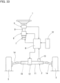
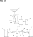
- Fig. 1 shows a steer-by-wire type steering system according to the first embodiment of the first invention.
- This steering system is a steer-by-wire type steering system for a vehicle that converts the operation amount of a steering wheel 1 by the driver into an electric signal, and controls a steering actuator 2 based on the electric signal, thereby changing the direction of a pair of right and left steered wheels 3.
- This steering system includes a steering wheel 1 steered by the driver; a steering shaft 4 coupled to the steering wheel 1; a steering sensor 5 that detects the operation amount of the steering wheel 1; a reaction force motor 6 that applies a steering reaction force to the steering wheel 1; a brake unit (electromagnetic clutch unit) 7 configured such that when one of an energized state and a de-energized state is switched to the other state, one of a steering locked state in which rotation of the steering wheel 1 is prevented and a steering unlocked state in which rotation of the steering wheel 1 is allowed is switched to the other state by the brake unit 7; a steering actuator 2 disposed to be mechanically separated from the steering wheel 1; and a control unit 8.
- a steering wheel 1 steered by the driver
- a steering shaft 4 coupled to the steering wheel 1
- a steering sensor 5 that detects the operation amount of the steering wheel 1
- a reaction force motor 6 that applies a steering reaction force to the steering wheel 1
- a brake unit (electromagnetic clutch unit) 7
- the steering shaft 4 is coupled to the steering wheel 1 so as to rotate in unison with the steering wheel 1 when the steering wheel 1 is steered.
- the steering sensor 5 is mounted to the steering shaft 4.
- the steering sensor 5 may be, for example, a steering angle sensor that detects the steering angle of the steering wheel 1, or a steering torque sensor that detects the steering torque applied to the steering wheel 1 by the driver.
- the reaction force motor 6 is an electric motor that generates rotational torque by energization.
- the reaction force motor 6 is coupled to an end of the steering shaft 4.
- the reaction force motor 6 applies rotational torque to the steering shaft 4 such that the steering reaction force is applied to the steering wheel 1 through the shaft 4.
- the steering actuator 2 includes a steering shaft 10; a steering shaft housing 11; a steering motor 12 that moves the steering shaft 10 in the right- and-left direction of the vehicle; and a steering sensor 13 that detects the position of the steering shaft 10.
- the steering shaft 10 is supported by the steering shaft housing 11 so as to be movable in the right-to-left direction of the vehicle.
- the steering shaft housing 11 receives the central portion of the steering shaft 10 such that the right and left ends of the steering shaft 10 protrude beyond the steering shaft housing 11.
- the steering motor 12 and the steering sensor 13 are mounted to the steering shaft housing 11.
- a motion converting mechanism (not shown) is mounted between the steering motor 12 and the steering shaft 10 so as to convert the rotation output from the steering motor 12, into the linear motion of the steering shaft 10.
- the right and left ends of the steering shaft 10 are coupled, respectively, to the right and left steered wheels 3 via tie rods 14 such that when the steering shaft 10 axially moves, the direction of the right and left steered wheels 3 change accordingly.
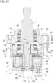
- the reaction force motor 6 includes a motor case 15, and a motor shaft 16 protruding beyond the motor case 15 toward the side opposite/remote from the steering wheel 1 (see Fig. 1 ) (toward the lower side in Fig. 2 ).
- the motor shaft 16 is rotatably supported by a rolling bearing (not shown) mounted in the motor case 15.
- the motor shaft 16 is coupled to the steering shaft 4 (see Fig. 1 ) so as to rotate in unison with the steering wheel 1 and the steering shaft 4 (see Fig. 1 ).
- the motor case 15 is fixed to the vehicle body (not shown) so as to be non-rotatable.
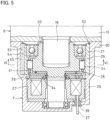
- the brake unit 7 includes an inner ring 20 coupled to the motor shaft 16; an outer ring 21 fixed to the motor case 15; a plurality of cam surfaces 22 (see Fig. 4 ) formed on the outer periphery of the inner ring 20; a cylindrical surface 23 formed on the inner periphery of the outer ring 21; engagement elements 24 disposed between the cylindrical surface 23 and the respective cam surfaces 22; an engagement element cage 25 retaining the engagement elements 24; an armature 26 supported to be axially movable; an electromagnet 27 that attracts the armature 26 so as to axially move when the electromagnet 27 is energized; and a motion converting mechanism 28 that circumferentially moves the engagement element cage 25 according to the movement of the armature 26.
- the inner ring 20 is fitted on the outer periphery of the motor shaft 16 via/by splines. Due to this spline fitting, the motor shaft 16 is coupled in a play-free state to the inner ring 20 so as not to rotate relative to the inner ring 20 at all.
- the outer ring 21 is integrally formed with a brake case (clutch case) 29.
- the brake case 29 is a tubular member in which constituent parts of the brake unit 7 (the inner ring 20, the engagement elements 24, the engagement element cage 25, the armature 26, the electromagnet 27, etc.) are received all together.
- a radially outwardly extending flange 30 is formed at one axial end of the brake case 29, and the flange 30 is fixed to the axial end surface of the motor case 15 by bolts (not shown).
- a bearing 31 is mounted to the outer ring 21 so as to rotatably support the inner ring 20.
- the brake case 29 is kept fixed not to rotate even when the steering wheel 1 (see Fig. 1 ) is steered. Also, by forming the outer ring 21 integrally with the brake case 29, the outer ring 21 is coupled to the brake case 29.
- cam surfaces 22 of the inner ring 20 on its outer periphery are radially opposed to the cylindrical surface 23 of the outer ring 21 on its inner periphery.
- a wedge-shaped space which gradually narrows from its circumferential center toward both circumferential ends thereof is defined between each cam surface 22 and the cylindrical surface 23.
- the engagement element cage 25 has a plurality of pockets 32 (see Fig. 2 ) radially extending through the cage 25 and circumferentially spaced apart from each other.
- the engagement elements 24 are received in the respective pockets 32.
- the engagement element cage 25 is supported to be circumferentially movable, relative to the inner ring 20, between an engagement position where by circumferentially moving the engagement elements 24 from the circumferential central positions of the respective cam surfaces 22 (see Fig. 4 ), the engagement elements 24 are engaged with the respective cam surfaces 22 and the cylindrical surface 23, and a disengagement position where by moving the engagement elements 24 to the circumferential central positions of the respective cam surfaces 22, the engagement elements 24 are disengaged from the respective cam surfaces 22 and the cylindrical surface 23.
- the armature 26 is axially movably supported by the outer periphery of an inner ring shaft portion 33 integrally formed with the inner ring 20.
- the armature 26 is a disk-shaped member made of a magnetic material (such as iron or silicon steel).
- the electromagnet 27 is axially opposed to the armature 26.
- the electromagnet 27 is fixed to the brake case 29 so as to move neither axially nor circumferentially.
- a separation spring 34 is mounted between the armature 26 and the electromagnet 27 so as to bias the armature 26 in the direction in which the armature 26 is separated (moves away) from the electromagnet 27.
- the electromagnet 27 includes an annular field core 35 having a C-shaped cross section axially opening toward the armature 26; and a solenoid coil 36 wound around the field core 35.
- the brake case 29 is formed with a through hole 38 through which a lead wire 37 for supplying electric power to the solenoid coil 36 passes.
- a grommet 39 made of rubber is mounted in the through hole 38 so as to fill the gap between the inner periphery of the through hole 38 and the outer periphery of the lead wire 37.
- the motion converting mechanism 28 includes an intermediate plate 40 that is rotationally fixed to the armature 26 so as to be axially movable relative to the armature 26, and that is rotationally fixed to the engagement element cage 25; and a centering spring 41 that elastically holds the engagement element cage 25 at the disengagement position.
- the intermediate plate 40 has, on its outer periphery, an engaging projection 43 engaged in an engaging recess 42 formed in the engagement element cage 25. By the engagement between the engaging projection 43 and the engaging recess 42, the intermediate plate 40 is rotationally fixed to the engagement element cage 25 so as to circumferentially move in unison with the engagement element cage 25.
- the intermediate plate 40 is formed with an axial protrusion 44 axially extending toward the armature 26.
- the armature 26 is formed with an axial hole 45 in which the axial protrusion 44 of the intermediate plate 40 is axially slidably inserted.
- the intermediate plate 40 is rotationally fixed to the armature 26 so as to circumferentially move in unison with the armature 26 in a state in which it is axially movable with respect to the armature 26.
- the centering spring 41 comprises a C-shaped annular portion 46 formed of a steel wire wound into a C-shape; and a pair of extending portions 47 extending radially outward from both ends of the C-shaped annular portion 46, respectively.
- the C-shaped annular portion 46 is fitted in a circular, spring receiving recess 48 formed in an axial end surface of the inner ring 20.
- the pair of extending portions 47 are inserted in a radial groove 49 formed in an axial end surface of the inner ring 20 so as to penetrate radially outward from the spring receiving recess 48.
- the extending portions 47 of the centering spring 41 protrude beyond the radially outer end of the radial groove 49, and the portions of the extending portions 47 protruding from the radial groove 49 are inserted in a cage groove 50 formed in the engagement element cage 25.
- the radial groove 49 and the cage groove 50 are formed to have the same circumferential width.
- the extending portions 47 of the centering spring 41 are in contact with the inner surface of the radial groove 49 and the inner surface of the cage groove 50, and elastically retain the engagement element cage 25 at the disengagement position by circumferential forces acting on the contact portions.
- the brake unit 7 shown in Fig. 2 is in an idling state in which the inner ring 20 can freely rotate with respect to the outer ring 21. That is, when the electromagnet 27 is de-energized, the armature 26 is separated from the electromagnet 27 by the biasing force of the separation spring 34, and the armature 26 is freely rotatable with respect to the electromagnet 27.
- the brake unit 7 in a state where the electromagnet 27 is energized, the brake unit 7 is in a locked state in which relative rotation of the inner ring 20 is prevented. That is, when the electromagnet 27 is energized, the armature 26 is attracted and stuck to the electromagnet 27, and the armature 26 is brought into frictional contact with the electromagnet 27. Since the armature 26 in frictional contact with the electromagnet 27 is rotationally fixed to the engagement element cage 25 via the intermediate plate 40, when the inner ring 20 is rotated in this state, the rotation of the engagement element cage 25 is restricted, and the inner ring 20 therefore rotates relative to the engagement element cage 25.
- the engagement element cage 25 moves from the disengagement position to the engagement position against the elastic force of the centering spring 41, and the engagement elements 24 are engaged with the cam surfaces 22 on the outer periphery of the inner ring 20 and the cylindrical surface 23 on the inner periphery of the outer ring 21, so that rotation of the inner ring 20 is prevented, and the motor shaft 16 coupled to the inner ring 20 is therefore prevented from rotating.
- the reaction force motor 6, the brake unit 7, and the steering motor 12 shown in Fig. 1 are controlled by the control unit 8.
- An external sensor 51, the steering sensor 5, and the steering sensor 13 are electrically connected to the input side of the control unit 8.
- the external sensor 51 is a vehicle speed sensor or the like that detects a traveling speed of the vehicle.
- the reaction force motor 6, the brake unit 7, and the steering actuator 2 are electrically connected to the output side of the control unit 8.
- the control unit 8 performs control to activate the steering motor 12 according to the operation amount of the steering wheel 1 detected by the steering sensor 5, and the traveling situation (vehicle speed or the like) of the vehicle detected by the external sensor 51 so as to change the direction of the pair of right and left steered wheels 3. At this time, the control unit 8 performs control to activate the reaction force motor 6 such that a steering reaction force having a magnitude according to the operation amount of the steering wheel 1 and the traveling situation of the vehicle is generated.
- the control unit 8 further determines whether the direction of the steered wheels 3 has reached the stroke end on the basis of the position of the steering shaft 10 detected by the steering sensor 13.
- the electromagnet 27 (see Fig. 2 ) of the brake unit 7 is de-energized to hold the engagement element cage 25 at the disengagement position.
- the electromagnet 27 (see Fig. 2 ) of the brake unit 7 is energized to move the engagement element cage 25 from the disengagement position to the engagement position.
- FIG. 5 and 6 show the second embodiment of the first invention.
- the second embodiment is different from the first embodiment only in the configurations of the outer ring 21 and the brake case 29, and the other configurations are the same. Therefore, the elements of the second embodiment corresponding to those of the first embodiment are denoted by the same numerals, and the description thereof is omitted.
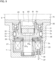
- the outer ring 21 is formed separately from the brake case 29.
- the brake case 29 is made of a non-magnetic material (such as aluminum alloy or copper alloy).
- the outer ring 21 is formed of a steel material.
- the outer ring 21 is fitted in the brake case 29, which has a tubular shape, and is prevented from moving out of the brake case 29 by a stop ring 52 mounted on the inner periphery of the brake case 29. As shown in Fig.
- a common key member 55 is fitted in a key groove 53 formed in the inner periphery of the brake case 29, and a key groove 54 formed in the outer periphery of the outer ring 21, and the outer ring 21 is rotationally fixed to the brake case 29 by the key member 55.
- the outer ring 21 is coupled to the brake case 29 by being rotationally fixed to the brake case 29 by the key member 55.
- the brake case 29 is formed of a non-magnetic material, when the electromagnet 27 is energized, the magnetic flux generated from the electromagnet 27 can be prevented from leaking to the brake case 29, so that the armature 26 can be efficiently attracted. Therefore, it is possible to reduce the sizes of the electromagnet 27 and the armature 26, and therefore possible to save space.
- Figs. 7 and 8 show the third embodiment of the first invention.
- the third embodiment is different from the second embodiment in that while, in the second embodiment, the brake unit 7 is mounted to the side of the reaction force motor 6 opposite/remote from the steering wheel 1 (attached on the lower side in the relevant drawing), in the third embodiment, the brake unit 7 is mounted to the side of the reaction force motor 6 close to the steering wheel 1 (attached on the upper side in the relevant drawing) in a vertically inverted manner.
- the other configurations are basically the same. Therefore, the elements of the third embodiment corresponding to those of the second embodiment are denoted by the same numerals, and the description thereof is omitted.
- the reaction force motor 6 includes a motor case 15, and a motor shaft 16 protruding beyond the motor case 15 toward the steering wheel 1 (see Fig. 7 ) (toward the upper side in Fig. 7 ).
- the brake unit 7 includes an inner ring 20 coupled to the steering shaft 4; an outer ring 21 fixed to the motor case 15; a plurality of cam surfaces 22 formed on the outer periphery of the inner ring 20; a cylindrical surface 23 formed on the inner periphery of the outer ring 21; engagement elements 24 disposed between the cylindrical surface 23 and the respective cam surfaces 22; an engagement element cage 25 that retains the engagement elements 24; an armature 26 supported to be axially movable; an electromagnet 27 that attracts the armature 26 so as to axially move when the electromagnet 27 is energized; and a motion converting mechanism 28 that circumferentially moves the engagement element cage 25 according to the movement of the armature 26.
- the inner ring 20 is coupled to the steering shaft 4 via an inner ring shaft portion 33 formed integrally with the inner ring 20.
- the inner ring shaft portion 33 and the steering shaft 4 are integrally formed, but the inner ring shaft portion 33 and the steering shaft 4 may be separate members connected so as to rotate in unison.
- the engagement element cage 25 is retained at the disengagement position in a state where the electromagnet 27 is de-energized, even when the inner ring 20 is rotated, the engagement elements 24 do not engage with the cam surfaces 22 on the outer periphery of the inner ring 20 and the cylindrical surface 23 on the inner periphery of the outer ring 21, and the inner ring 20 and the steering shaft 4 can therefore freely rotate in both normal and reverse directions.
- the engagement element cage 25 moves from the disengagement position to the engagement position, and the engagement elements 24 engage with the cam surfaces 22 on the outer periphery of the inner ring 20 and the cylindrical surface 23 on the inner periphery of the outer ring 21, so that rotation of the inner ring 20 is prevented, and the steering shaft 4, which is coupled to the inner ring 20, is also prevented from rotating.
- the steering wheel 1 As in the first embodiment, also for the steering system for a vehicle of the third embodiment of the first invention, by switching between the energized state and the de-energized state of the electromagnet 27 when the direction of the steered wheels 3 (see Fig. 7 ) reaches the stroke end, the steering wheel 1 (see Fig. 7 ) is reliably prevented from further rotating, so that it is possible to cause the driver to reliably sense, via the steering wheel 1, that the direction of the steered wheels 3 has reached the stroke end.
- Figs. 9 and 10 show the fourth embodiment of the first invention.
- the fourth embodiment is different from the first embodiment only in the coupling structure between the inner ring 20 and the motor shaft 16, and the other configurations are the same. Therefore, therefore, the elements of the fourth embodiment corresponding to those of the first embodiment are denoted by the same numerals, and the description thereof is omitted.
- the motor shaft 16 includes a non-circular shaft portion 60 having a non-circular cross section.
- the inner ring 20 is formed with a non-circular hole portion 61 in which the non-circular shaft portion 60 of the motor shaft 16 is fitted with a circumferential gap defined.
- rotation stopper surfaces 62 and an elastic member holding portion 63 are formed axially side by side (see Fig. 12 ).
- the rotation stopper surfaces 62 are received in direct contact with the inner periphery of the non-circular hole portion 61 when the motor shaft 16 rotates relative to the inner ring 20.
- the rotation stopper surfaces 62 are formed on both sides, i.e., on one circumferential side and the other circumferential side of the non-circular shaft portion 60.
- the rotation stopper surface 62 on the one circumferential side is received in direct contact with the inner periphery of the non-circular hole portion 61, and when the motor shaft 16 rotates relative to the inner ring 20 in the other circumferential direction, the rotation stopper surface 62 on the other circumferential side is received in direct contact with the inner periphery of the non-circular hole portion 61.
- the elastic member holding portion 63 holds elastic members 64.
- the elastic members 64 are leaf springs in this embodiment.
- Each of the elastic members 64 includes a first leaf spring portion 67a circumferentially sandwiched between a surface 65a opposed to one circumferential side of the elastic member holding portion 63 and an inner surface 66a of the non-circular hole portion 61 opposed to the surface 65a in the circumferential direction, and a second leaf spring portion 67b circumferentially sandwiched between a surface 65b opposed to the other circumferential side of the elastic member holding portion 63 and an inner surface 66b of the non-circular hole portion 61 opposed to the surface 65b in the circumferential direction.
- Each of the elastic members 64 elastically holds the motor shaft 16 in such a manner that the second leaf spring portion 67b biases the non-circular shaft portion 60 to one circumferential side, and, at the same time, the first leaf spring portion 67a biases the non-circular shaft portion 60 to the other circumferential side such that both of the biasing forces are balanced.
- the elastic member holding portion 63 is formed to have the surfaces 65a and 65b at positions retracted in the circumferential direction from the rotation stopper surfaces 62 so that the elastic members 64 are not excessively compressed and permanently deformed when the motor shaft 16 rotates relative to the inner ring 20 to a position where the rotation stopper surfaces 62 are received by the inner periphery of the non-circular hole portion 61.
- the non-circular shaft portion 60 and the non-circular hole portion 61 couple the inner ring 20 and the motor shaft 16 to each other with such play of a predetermined angular range of the motor shaft 16 with respect to the inner ring 20 that the motor shaft 16 is allowed to relatively rotate with respect to the inner ring 20 within a predetermined angular range (the angular range of a predetermined angle in both normal and reverse directions with respect to the central position of the angular range, where the predetermined angle is 5° or more and 15° or less (about 10° in the relevant drawing)) and that the motor shaft 16 is prevented from relatively rotating beyond the predetermined angular range.
- a predetermined angular range the angular range of a predetermined angle in both normal and reverse directions with respect to the central position of the angular range, where the predetermined angle is 5° or more and 15° or less (about 10° in the relevant drawing)
- the elastic members 64 (the first leaf spring portions 67a and the second leaf spring portions 67b) are elastically deformed when the inner ring 20 and the motor shaft 16 rotate relative to each other from a state where the inner ring 20 and the motor shaft 16 are at the central position in the predetermined angular range, and the elastic restoring force biases the inner ring 20 and the motor shaft 16 toward the central position (the position in Fig. 10 ) in the predetermined angular range.
- the steering system for a vehicle of the fourth embodiment of the first invention can prevent a situation where the steering wheel 1 is locked and does not move in a case where the direction of the steered wheels 3 (see fig. 1 ) has reached the stroke end and the driver senses the situation via the steering wheel 1 and suddenly tries to turn the steering wheel 1 in the opposite/reverse direction (the direction in which the direction of the steered wheels 3 returns from the stroke end).
- the motor shaft 16 is coupled to the inner ring 20 with play so as to allow relative rotation within the predetermined angular range with respect to the inner ring 20. Therefore, when rotation of the steering wheel 1 shown in Fig. 1 is prevented in one direction of normal and reverse directions, the steering wheel 1 can be turned in the other direction of the normal and reverse directions by an angle corresponding to the play provided between the motor shaft 16 and the inner ring 20.
- Fig. 13 shows the fifth embodiment of the first invention.
- the fifth embodiment is different from the fourth embodiment only in the configurations of the elastic members 64, and the other configurations are the same. Therefore, the elements of the fifth embodiment corresponding to those of the fourth embodiment are denoted by the same numerals, and the description thereof is omitted.
- the elastic members 64 are compression coil springs in this embodiment.
- Each of the elastic members 64 includes a first coil spring 69a received in a spring receiving hole 68a formed in the non-circular shaft portion 60 so as to open toward one circumferential side such that the portion of the first coil spring 69a protruding beyond the spring receiving hole 68a is supported by the inner surface of the non-circular hole portion 61; and a second coil spring 69b received in a spring receiving hole 68b formed in the non-circular shaft portion 60 so as to open toward the other circumferential side such that the portion of the second coil spring 69b protruding beyond the spring receiving hole 68b is supported by the inner surface of the non-circular hole portion 61.
- Both the first coil spring 69a and the second coil spring 69b are kept compressed in the circumferential direction between the non-circular shaft portion 60 and the non-circular hole portion 61.
- the first coil spring 69a and the second coil spring 69b are elastically deformed when the inner ring 20 and the motor shaft 16 rotate relative to each other from a state where the inner ring 20 and the motor shaft 16 are at the central position in a predetermined angular range, and the elastic restoring force biases the inner ring 20 and the motor shaft 16 toward the central position in the predetermined angular range.
- the steering system for a vehicle of the fifth embodiment of the first invention has the same functions and effects as in the fourth embodiment.
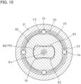
- Figs. 14 and 15 show the sixth embodiment of the first invention.
- the sixth embodiment is different from the fourth embodiment in the configuration of the elastic members 64, and the other configurations are basically the same. Therefore, the elements of the sixth embodiment corresponding to those of the fourth embodiment are denoted by the same numerals, and the description thereof is omitted.
- the brake unit 7 includes an intermediate shaft 70 coupled to the motor shaft 16; an inner ring 20 coupled to the motor shaft 16 via the intermediate shaft 70; an outer ring 21 fixed to the motor case 15; a plurality of cam surfaces 22 formed on the outer periphery of the inner ring 20; a cylindrical surface 23 formed on the inner periphery of the outer ring 21; engagement elements 24 disposed between the cylindrical surface 23 and the respective cam surfaces 22; an engagement element cage 25 retaining the engagement elements 24; an armature 26 supported to be axially movable; an electromagnet 27 that attracts the armature 26 so as to axially move when the electromagnet 27 is energized; and a motion converting mechanism 28 that circumferentially moves the engagement element cage 25 according to the movement of the armature 26.
- the intermediate shaft 70 is spline-fitted to the motor shaft 16. Due to this spline fitting, the intermediate shaft 70 is coupled to the motor shaft 16 with no play so as not to rotate relative to the motor shaft 16 at all.
- the intermediate shaft 70 includes a non-circular shaft portion 60 having a non-circular cross section.
- the inner ring 20 is formed with a non-circular hole portion 61 in which the non-circular shaft portion 60 of the intermediate shaft 70 is fitted with a circumferential gap defined.
- Rotation stopper surfaces 62 are formed on the outer periphery of the non-circular shaft portion 60.
- the rotation stopper surfaces 62 are received in direct contact with the inner periphery of the non-circular hole portion 61 when the intermediate shaft 70 rotates relative to the inner ring 20.
- the rotation stopper surfaces 62 are formed on both sides, i.e., on one circumferential side and the other circumferential side of the non-circular shaft portion 60.
- the non-circular shaft portion 60 and the non-circular hole portion 61 couple the inner ring 20 and the intermediate shaft 70 to each other with such play of a predetermined angular range of the intermediate shaft 70 with respect to the inner ring 20 that the intermediate shaft 70 is allowed to relatively rotate with respect to the inner ring 20 within a predetermined angular range and that the intermediate shaft 70 is prevented from relatively rotating beyond the predetermined angular range.
- the elastic member 64 is a torsion bar in this embodiment.
- One end of the elastic member 64 is rotationally fixed to the intermediate shaft 70 with the one end spline-fitted in a fitting hole 71 formed at the center of the intermediate shaft 70, and the other end of the elastic member 64 is also rotationally fixed to the inner ring 20 with the other end spline-fitted in a fitting hole 72 formed in the inner ring 20.
- the elastic member 64 biases the inner ring 20 and the intermediate shaft 70 toward the central position of a predetermined angular range when the inner ring 20 and the intermediate shaft 70 relatively rotate from the central position of the predetermined angular range.
- the steering system for a vehicle of the sixth embodiment of the first invention has the same functions and effects as in the fourth embodiment.
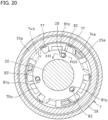
- Figs. 16 to 22 show the seventh embodiment of the first invention.
- the seventh embodiment is different from the first embodiment in the configuration of the motion converting mechanism 28. That is, the motion converting mechanism 28 of the first embodiment is configured to circumferentially move the engagement element cage 25 from the disengagement position to the engagement position when the electromagnet 27 is energized, and circumferentially move the engagement element cage 25 from the engagement position to the disengagement position when the electromagnet 27 is de-energized (that is, an excited operation type clutch is used that engages due to energization, as the brake unit 7).
- the motion converting mechanism 28 of the seventh embodiment is configured to circumferentially move the engagement element cage 25 from the engagement position to the disengagement position when the electromagnet 27 is energized, and circumferentially move the engagement element cage 25 from the disengagement position to the engagement position when the electromagnet 27 is de-energized (that is, as the brake unit 7, a non-excited operation type clutch is used that engages due to deenergization).
- the elements of the seventh embodiment corresponding to those of the first embodiment are denoted by the same numerals, and the description thereof is omitted.
- the brake unit 7 includes an inner ring 20 coupled to the motor shaft 16; an outer ring 21 non-rotatably fixed; a plurality of cam surfaces 22 formed on the outer periphery of the inner ring 20; a cylindrical surface 23 formed on the inner periphery of the outer ring 21; a plurality of engagement elements 24a and 24b disposed between the cylindrical surface 23 and the respective cam surfaces 22; an engagement element cage 25 that retains the engagement elements 24a and 24b; an armature 26 supported to be axially movable; an electromagnet 27 that attracts the armature 26 so as to axially move when the electromagnet 27 is energized; and a motion converting mechanism 28 that circumferentially moves the engagement element cage 25 according to the movement of the armature 26.
- the inner ring 20 is spline-fitted to the outer periphery of the motor shaft 16, and the motor shaft 16 is coupled to the inner ring 20 due to this spline fitting.
- a structure may be adopted in which the inner ring 20 and the motor shaft 16 are coupled together with play of a predetermined angular range, and the elastic member (or members) 64 is disposed between the inner ring 20 and the motor shaft 16.
- the outer ring 21 is formed separately from the brake case 29.
- the brake case 29 is made of a non-magnetic material (such as aluminum alloy or copper alloy).
- the outer ring 21 is formed of a steel material.
- the outer ring 21 is rotationally fixed to the brake case 29 by fitting a common key member 55 into a key groove 53 formed in the inner periphery of the brake case 29 and a key groove 54 formed in the outer periphery of the outer ring 21.
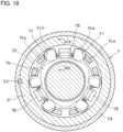
- a plurality of cam surfaces 22 are disposed on the outer periphery of the inner ring 20 at circumferentially equal intervals.
- Each of the cam surfaces 22 comprises a front cam surface portion 22a and a rear cam surface portion 22b disposed rearward of the front cam surface 22a in the normal rotational direction of the inner ring 20.
- the outer ring 21 has, on its the inner periphery, a cylindrical surface 23 radially opposed to the front cam surface portions 22a and the rear cam surface portions 22b.
- each cam surface 22 and the cylindrical surface 23 a pair of engagement elements 24a and 24b are disposed which are opposed to each other in the circumferential direction with an engagement element separation spring 73 interposed therebetween.
- the engagement element 24a on the front side in the normal rotational direction is disposed between the corresponding front cam surface portion 22a and the cylindrical surface 23
- the engagement element 24b on the rear side in the normal rotational direction is disposed between the corresponding rear cam surface portion 22b and the cylindrical surface 23.
- Each engagement element separation spring 73 presses the corresponding pair of engagement elements 24a and 24b in the direction in which the distance between the engagement elements 24a and 24b is increased.
- Each of the front cam surface portions 22a is formed such that the radial distance between the front cam surface portion 22a and the cylindrical surface 23 gradually decreases toward the front side in the normal rotational direction from the position of the corresponding engagement element 24a.
- Each of the rear cam surface portions 22b is formed such that the radial distance between the rear cam surface portion 22b and the cylindrical surface 23 gradually decreases toward the rear side in the normal rotational direction from the position of the corresponding engagement element 24b.
- the engagement element cage 25 comprises a first split cage portion 25a supporting, of the circumferentially opposed engagement elements 24a and 24b with the engagement element separation springs 73 disposed between the respective pairs of engagement elements 24a and 24b, the engagement elements 24a; and a second split cage portion 25b supporting the other engagement elements 24b.
- the first split cage portion 25a and the second split cage portion 25b are supported so as to be rotatable relative to each other, and individually support each pair of engagement elements 24a and 24b such that the distance between the engagement elements 24a and 24b changes according to the relative rotation.
- the first split cage portion 25a includes a plurality of pillars 74a circumferentially spaced apart from each other; and an annular flange 75a that couples the ends of the pillars 74a to each other.
- the second split cage portion 25b includes a plurality of pillars 74b circumferentially spaced apart from each other; and an annular flange 75b that couples the ends of the pillars 74b to each other.
- the pillars 74a of the first split cage portion 25a and the pillars 74b of the second split cage portion 25b are inserted between the inner periphery of the outer ring 21 and the outer periphery of the inner ring 20 such that each pillar 74a and the corresponding pillar 74b circumferentially sandwich, from both sides in the circumferential direction, the pair of engagement elements 24a and 24b, which are circumferentially opposed to each other with the engagement element separation spring 73 located therebetween.
- the inner periphery of the flange 75a of the first split cage portion 25a and the inner periphery of the flange 75b of the second split cage portion 25b are rotatably supported on the outer periphery of the inner ring 20.
- the first split cage portion 25a and the second split cage portion 25b are circumferentially movable between (i) an engagement position at which by increasing the interval between each pair of engagement elements 24a and 24b, the engagement elements 24a and 24b are engaged with the cam surfaces 22 and the cylindrical surface 23; and (ii) a disengagement position at which by decreasing the interval between each pair of engagement elements 24a and 24b, the engagement elements 24a and 24b are disengaged from the cam surfaces 22 and the cylindrical surface 23.
- a spring holder 76 is fixed to a side surface of the inner ring 20.
- the spring holder 76 includes stopper pieces 77 located between each pair of pillars 74a and 74b which are circumferentially opposed to each other, and between which the corresponding pair of engagement elements 24a and 24b are interposed.
- the stopper pieces 77 receive the corresponding pillars 74a and 74b when the pillars 74a and 74b move in the direction in which the distance between the engagement elements 24a and 24b is reduced.
- the spring holder 76 includes spring holding pieces 78 that hold the respective engagement element separation springs 73.
- the spring holding pieces 78 are integrally formed with the stopper pieces 77 so as to axially extend between the inner periphery of the outer ring 21 and the outer periphery of the inner ring 20.
- a rotor 79 is disposed between the electromagnet 27 and the armature 26.
- the rotor 79 is fixed to the outer periphery of the inner ring 20.
- the rotor 79 is made of a magnetic material (such as iron or silicon steel).
- the armature 26 includes a cylindrical portion 80 fitted to the outer periphery of the second split cage portion 25b with an interference, and due to the fitting of the cylindrical portion 80, the armature 26 is coupled to the second split cage portion 25b so as to axially move in unison with the second split cage portion 25b.
- the motion converting mechanism 28 includes inclined grooves 81a disposed in, of the flange 75a of the first split cage portion 25a, the surface opposed to the flange 75b of the second split cage portion 25b; inclined grooves 81b disposed in, of the flange 75b of the second split cage portion 25b, the surface opposed to the flange 75a of the first split cage portion 25a; and balls 82 disposed between the inclined grooves 81a and the respective inclined grooves 81b.
- the inclined grooves 81a and the inclined grooves 81b are formed so as to circumferentially extend.
- Each inclined groove 81a has a shape having a groove bottom inclined so as to be gradually shallower in one circumferential direction from a deepest portion 83a having the deepest axial depth
- each inclined groove 81b also has a shape having a groove bottom inclined so as to be gradually shallower in the other circumferential direction from a deepest portion 83b having the deepest axial depth.
- the motion converting mechanism 28 is configured such that when the armature 26 is attracted to the electromagnet 27, and the flange 75b of the second split cage portion 25b axially moves, together with the armature 26, toward the flange 75a of the first split cage portion 25a, the balls 82 roll toward the deepest portions 83a and 83b of the inclined grooves 81a and 81b, whereby the first split cage portion 25a and the second split cage portion 25b relatively rotate in the direction in which the pillars 74a and 74b reduce the intervals between the engagement elements 24a and 24b, and the relative rotation causes the engagement element cage 25 to move from the engagement position to the disengagement position.
- the armature 26 is biased in the direction away from the rotor 79 by the forces of the engagement element separation springs 73. That is, the force by which each engagement element separation spring 73 shown in Fig. 17 presses the engagement elements 24a and 24b in the direction in which the distance between the engagement elements 24a and 24b is increased is transmitted to the first split cage portion 25a and the second split cage portion 25b. Then, the circumferential force received by the first split cage portion 25a and the second split cage portion 25b is converted into the axial force in the direction away from the rotor 79 by the motion converting mechanism 28 shown in Figs. 20 to 22 , and the converted force is transmitted to the second split cage portion 25b.
- the armature 26 since the armature 26 is fixed to the second split cage portion 25b, the armature 26 is therefore biased in the direction away from the rotor 79 by the forces transmitted from the engagement element separation springs 73 via the motion converting mechanism 28.
- the brake unit 7 While the electromagnet 27 shown in Fig. 16 is de-energized, the brake unit 7 is in a locked state in which rotation of the inner ring 20 is prevented. That is, when the electromagnet 27 is de-energized, the armature 26 axially moves in the direction away from the rotor 79 by the forces of the engagement element separation springs 73.
- the brake unit 7 is in an idling state in which the inner ring 20 can freely rotate with respect to the outer ring 21. That is, when the electromagnet 27 is energized, the armature 26 is attracted and stuck to the rotor 79, and, in conjunction with the motion of the armature 26, the flange 75b of the second split cage portion 25b axially moves toward the flange 75a of the first split cage portion 25a. At this time, the balls 82 of the motion converting mechanism 28 roll toward the deepest portions 83a and 83b of the inclined grooves 81a and 81b, and the engagement element cage 25 therefore circumferentially moves from the engagement position to the disengagement position.
- the engagement elements 24a on the front side in the normal rotational direction are disengaged from the front cam surfaces 22a and the cylindrical surface 23
- the engagement elements 24b on the rear side in the normal rotational direction are disengaged from the rear cam surfaces 22b and the cylindrical surface 23 and, and the inner ring 20 and the motor shaft 16 can freely rotate in both normal and reverse directions.
- the steering wheel 1 is reliably prevented from further rotating, so that it is possible to cause the driver to reliably sense, via the steering wheel 1, that the direction of the steered wheels 3 has reached the stroke end.
- the steering system for a vehicle of the seventh embodiment of the first invention is switched (i) from the steering locked state to the steering unlocked state when the electromagnet 27 is energized, and (ii) from the steering unlocked state to the steering locked state when the electromagnet 27 is de-energized. Therefore, when the power of the vehicle is turned off and the electromagnet 27 is de-energized, for example, at the time of parking the vehicle, the steering wheel 1 is brought into the steering locked state in which rotation of the steering wheel is prevented, so that it is possible to add a steering wheel locking function for preventing theft of the vehicle without providing a separate steering wheel locking mechanism.
- the outer ring 21 is formed separately from the brake case 29, and the outer ring 21 is rotationally fixed to the brake case 29, as shown in Fig. 23 , the outer ring 21 may be formed integrally with the brake case 29.
- Figs. 24 to 27 show the eighth embodiment of the first invention.
- the eighth embodiment is different from the second embodiment only in the configuration for axially fixing the outer ring 21 and the electromagnet 27, and the other configurations are basically the same. Therefore, the elements of the eighth embodiment corresponding to those of the second embodiment are denoted by the same numerals, and the description thereof is omitted.
- the electromagnet 27 is disposed in the brake case 29 so as to be axially opposed to the outer ring 21.
- the brake case 29 includes a cylindrical portion 29a fitted to the outer periphery of the field core 35 of the electromagnet 27; and an end plate portion 29b supporting an axial end surface of the field core 35 of the electromagnet 27.
- the end plate portion 29b constitutes an electromagnet movement restricting portion that restricts the movement of the electromagnet 27 in one axial direction (downward in the drawing).
- a stop ring 52 mounted to the inner periphery of an opening end of the cylindrical portion 29a constitutes an outer ring movement restricting portion that restricts the movement range of the other axial direction (upward in the drawing) of the outer ring 21.
- the end plate portion 29b is integrally formed with the cylindrical portion 29a.
- the end plate portion 29b is formed with an anti-rotation hole 85 in which an anti-rotation protrusion 84 formed on an axial end surface of the field core 35 is inserted.
- the electromagnet 27 is circumferentially positioned with respect to the brake case 29 by the engagement of the anti-rotation protrusion 84 in the anti-rotation hole 85.
- a rolling bearing 86 that rotatably supports the inner ring 20 is mounted to the end plate portion 29b.
- An annular elastic spacer 87 is mounted between the outer ring 21 and the electromagnet 27.
- the elastic spacer 87 is mounted in an axially compressed state, and biases, by its elastic restoring force, the outer ring 21 and the electromagnet 27 in the directions in which the outer ring 21 and the electromagnet 27 are moved away from each other in the axial direction.
- One axial end of the elastic spacer 87 presses the surface of the outer ring 21 axially opposed to the field core 35, and the other axial end of the elastic spacer 87 presses the surface of the field core 35 opposed to the outer ring 21.
- the elastic spacer 87 is made of a non-magnetic material (such as aluminum alloy or copper alloy).
- disc springs 87a can be used as the elastic spacer 87.
- the disc springs 87a are conical tubular metal springs. Only a single disk spring 87a can also be used as the elastic spacer 87; however, as shown in the drawing, if a plurality of disc springs 87a axially arranged with the large diameter side and the small diameter side being directed in alternate directions are used as the elastic spacer 87, the axial length of the elastic spacer 87 can be ensured. Since the disc springs 87a can generate a large force in narrow installation space, if disc springs 87a are used as the elastic spacer 87, the axial movements of the outer ring 21 and the electromagnet 27 can be reliably restricted.
- wave springs 87b can also be used as the elastic spacer 87.
- the wave springs 87b are annular metal springs each formed such that a waveform is repeated along the circumferential direction. Only the wave springs 87b can also be used as the elastic spacer 87; however, as shown in the drawing, if the wave springs 87b and annular flat washers 87c alternately arranged in the axial direction are used as the elastic spacer 87, the axial length of the elastic spacer 87 can be ensured.
- a compression coil spring 87d is a spring formed by spirally winding a metal wire. If the compression coil spring 87d is used as the elastic spacer 87, the elastic spacer 87 can be disposed in a space having a small radial width.
- the steering system for a vehicle of the eighth embodiment of the first invention is low in machining cost of the brake case shown in Fig. 24 . That is, in a case where the outer ring 21 and the electromagnet 27 are disposed to be axially opposed to each other in the brake case 29, to axially fix the outer ring 21 and the electromagnet 27, it is considered to adopt an arrangement in which there are separately provided (i) a stop ring (not shown) to restrict the axial movement of the electromagnet 27 in the direction toward the outer ring 21 and (ii) a stop ring (not shown) to restrict the axial movement of the outer ring 21 in the direction toward the electromagnet 27, and stop ring grooves for mounting the respective stop rings are formed in the inner periphery of the brake case 29.
- the elastic spacer 87 shown in Fig. 24 is formed of a non-magnetic material in the steering system for a vehicle of the eighth embodiment of the first invention, when the electromagnet 27 is energized, the magnetic flux generated from the electromagnet 27 is prevented from leaking through the elastic spacer 87, so that the armature 26 can be efficiently attracted. Therefore, it is possible to reduce the sizes of the electromagnet 27 and the armature 26 and therefore possible to save space.
- Fig. 28 shows the ninth embodiment of the first invention. While, in each of the above embodiments, the description has been given taking, as an example, the steering system for a vehicle whose steering target is a pair of right and left steered wheels 3 of a vehicle as shown in Fig. 1 or 7 , the steering system of the ninth embodiment is a steering system for a vessel whose steering target is a rudder (outboard motor or the like) on the stern of a vessel (not shown).
- the ninth embodiment of the first invention is different from the eighth embodiment in that in the eighth embodiment, the inner ring 20 is indirectly coupled to the steering shaft 4 (see Fig. 1 ) via the motor shaft 16 of the reaction force motor 6, but, in the ninth embodiment, the reaction force motor 6 is not disposed and the inner ring 20 is directly coupled to the steering shaft 4.
- the other configurations are basically the same. Therefore, the elements of the ninth embodiment corresponding to those of the eighth embodiment are denoted by the same numerals, and the description thereof is omitted.
- the steering shaft 4 is inserted in a steering insertion hole 89 formed in a dashboard panel 88 of a vessel.
- the end of the steering shaft 4 on the insertion side, which is inserted in the steering insertion hole 89, is spline-fitted to the inner ring 20.
- a radially outwardly extending flange 30 is formed at one axial end of the brake case 29, and the flange 30 is fixed to the dashboard panel 88 of the vessel by bolts (not shown).
- the steering wheel 1 is reliably prevented from further rotating, so that it is possible to cause the driver to reliably sense, via the steering wheel 1, that the direction of the rudder (outboard motor or the like) of the vessel (not shown) has reached the stroke end.
- Figs. 29 and 30 show the tenth embodiment of the first invention.
- the tenth embodiment corresponds to an embodiment in which the relation of the motor shaft 16 and the brake case 29 to the inner ring 20 and the outer ring 21 in the seventh embodiment is reversed.
- the tenth embodiment is different from the seventh embodiment in that in the seventh embodiment, of the inner ring 20 and the outer ring 21, the inner ring 20 is coupled to the motor shaft 16, and the outer ring 21 is coupled to the brake case 29, but, in the tenth embodiment, of the inner ring 20 and the outer ring 21, the outer ring 21 is coupled to the motor shaft 16, and the inner ring 20 is coupled to the brake case 29.
- the other configurations are basically the same. Therefore, the elements of the tenth embodiment corresponding to those of the seventh embodiment are denoted by the same numerals, and the description thereof is omitted.
- the brake unit 7 includes an outer ring 21 coupled to the motor shaft 16; an outer ring 21 coupled to the brake case 29; a plurality of cam surfaces 22 formed on the outer periphery of the inner ring 20; a cylindrical surface 23 formed on the inner periphery of the outer ring 21; a plurality of engagement elements 24a and 24b disposed between the cylindrical surface 23 and the cam surfaces 22; an engagement element cage 25 that retains the engagement elements 24a and 24b; an armature 26 supported to be axially movable; an electromagnet 27 that attracts the armature 26 so as to axially move when the electromagnet 27 is energized; and a motion converting mechanism 28 that circumferentially moves the engagement element cage 25 according to the movement of the armature 26.
- the outer ring 21 includes an outer ring end plate 21a axially opposed to an axial end of the inner ring 20; and an outer ring shaft portion 21b axially extending from the outer ring end plate 21a.
- the outer ring shaft portion 21b is spline-fitted to the motor shaft 16. Due to this spline fitting, the outer ring 21 is coupled to the motor shaft 16.
- the brake case 29 includes a cylindrical portion 29a fitted to the outer periphery of the field core 35 of the electromagnet 27; and an end plate portion 29b supporting an axial end surface of the field core 35 of the electromagnet 27.
- the end plate portion 29b is integrally formed with the cylindrical portion 29a.
- the end plate portion 29b is formed with an anti-rotation hole 85 in which an anti-rotation protrusion 84 formed on an axial end surface of the field core 35 is inserted.
- the electromagnet 27 is circumferentially positioned with respect to the brake case 29 by the engagement of the anti-rotation protrusion 84 in the anti-rotation hole 85.
- the inner ring 20 is coupled to the brake case 29 by being rotationally fixed to an inner ring coupling shaft 29c disposed on the end plate portion 29b of the brake case 29. It is also possible to couple the inner ring 20 and the inner ring coupling shaft 29c together without any play so as not to relatively rotate at all like the inner ring 20 and the motor shaft 16 shown in Fig. 2 . However, in this embodiment, the inner ring 20 and the inner ring coupling shaft 29c are coupled together with a predetermined play, like the inner ring 20 and the motor shaft 16 shown in Fig.
- the rotor 79 (see Fig. 16 ) is not disposed between the electromagnet 27 and the armature 26, and the armature 26 is directly opposed to the electromagnet 27.
- the armature 26 is biased in the direction away from the electromagnet 27 by the forces of the engagement element separation springs 73 (see Fig. 30 ). That is, the force by which the engagement element separation springs 73 shown in Fig. 30 each press the corresponding pair of the engagement elements 24a and 24b in the direction in which the distance between the pair of engagement elements 24a and 24b is increased is transmitted to the first split cage portion 25a and the second split cage portion 25b. Then, the circumferential force received by the first split cage portion 25a and the second split cage portion 25b is converted into the axial force in the direction away from the electromagnet 27 by the motion converting mechanism 28, and the converted force is transmitted to the second split cage portion 25b.
- the armature 26 is therefore biased in the direction away from the electromagnet 27 by the forces transmitted from the engagement element separation springs 73 (see Fig. 30 ) via the motion converting mechanism 28.
- the brake unit 7 While the electromagnet 27 shown in Fig. 29 is de-energized, the brake unit 7 is in a locked state in which rotation of the outer ring 21 is prevented. That is, when the electromagnet 27 is de-energized, the armature 26 axially moves in the direction away from the electromagnet 27 by the forces of the engagement element separation springs 73 (see Fig. 30 ).
- the brake unit 7 is in an idling state in which the outer ring 21 can freely rotate with respect to the inner ring 20. That is, when the electromagnet 27 is energized, the armature 26 is attracted and stuck to the electromagnet 27, and, in conjunction with the motion of the armature 26, the flange 75b of the second split cage portion 25b axially moves toward the flange 75a of the first split cage portion 25a. At this time, the relative axial movement of the first split cage portion 25a and the second split cage portion 25b is converted into the circumferential relative movements of the first split cage portion 25a and the second split cage portion 25b by the motion converting mechanism 28.
- the steering system for a vehicle of the tenth embodiment of the first invention is switched (i) from the steering locked state to the steering unlocked state when the electromagnet 27 is energized and (ii) from the steering unlocked state to the steering locked state when the electromagnet 27 is de-energized. Therefore, when the power of the vehicle is turned off and the electromagnet 27 is de-energized, for example, at the time of parking the vehicle, the steering wheel 1 is brought into the steering locked state in which rotation of the steering wheel is prevented, so that it is possible to add a steering wheel locking function for preventing theft of the vehicle without providing a separate steering wheel locking mechanism.
- the other functions and effects are also the same as those of the seventh embodiment.
- Fig. 31 shows the eleventh embodiment of the first invention.
- the eleventh embodiment is different from the tenth embodiment only in that while, in the tenth embodiment, the brake case 29 is formed separately from the motor case 15 of the reaction force motor 6, and the brake case 29 is fixed to the motor case 15, in the eleventh embodiment, the brake case 29 is integrally formed with the motor case 15 of the reaction force motor 6, and the other configurations are the same. Therefore, the elements of the eleventh embodiment corresponding to those of the tenth embodiment are denoted by the same numerals, and the description thereof is omitted.
- rollers are used as engagement elements 24, 24a, and 24bdisposed between the inner periphery of the outer ring 21 and the outer periphery of the inner ring 20.
- balls or sprags are used as the engagement elements.
- the description has been given taking, as an example of the steer-by-wire type steering system, a steering system for a vehicle whose steering target is a pair of right and left steered wheels 3 of a vehicle, and, in the ninth embodiment, the description has been given taking, as an example of the steer-by-wire type steering system according to the first invention, a steer-by-wire type steering system for a vessel whose steering target is a rudder (outboard motor or the like) disposed on the stern of a vessel.
- a steer-by-wire type steering system for a vessel whose steering target is a rudder (outboard motor or the like) disposed on the stern of a vessel.
- the first invention can be applied not only to the steering system for a vehicle and the steering system for a vessel, but also to the steering system for construction machines, agricultural machines, all-terrain vehicles, and multipurpose four-wheel vehicles in the same manner as long as they use a steer-by-wire type steering system.
- Figs. 32 and 33 show a steer-by-wire type steering system according to the first embodiment of the second invention as an example thereof.
- the elements of this first embodiment corresponding to those of the embodiments of the first invention are denoted by the same numerals, and the description thereof is omitted.
- the members/elements denoted by the same numerals are basically the same in configuration.
- This steering system includes a steering wheel 1 steered by the driver; a shaft 9 coupled to the steering wheel 1; a steering sensor 5 that detects the operation amount of the steering wheel 1; a reaction force motor 6 that applies a steering reaction force to the steering wheel 1; a brake unit 7 that, when in a non-excited state, prevents rotation of the steering wheel 1, and that, when in an excited state, allows rotation of the steering wheel 1; a steering actuator 2 disposed to be mechanically separated from the steering wheel 1; and a control unit 8.
- the shaft 9 is coupled to the steering wheel 1 so as to rotate in unison with the steering wheel 1 when the steering wheel 1 is steered.
- the steering sensor 5 is mounted to the shaft 9.
- the steering sensor 5 may be, for example, a steering angle sensor that detects the steering angle of the steering wheel 1, or a steering torque sensor that detects the steering torque applied to the steering wheel 1 by the driver.
- the reaction force motor 6 is an electric motor that generates rotational torque by energization.
- the reaction force motor 6 is coupled to an end of the shaft 9. By applying rotational torque to the shaft 9, the reaction force motor 6 applies the steering reaction force to the steering wheel 1 through the shaft 9.
- the reaction force motor 6 includes a motor case 15, and a motor shaft 16 protruding beyond the motor case 15 toward the side opposite/remote from the steering wheel 1 (toward the lower side in Fig. 2 ).
- the motor shaft 16 is rotatably supported by a rolling bearing (not shown) mounted in the motor case 15.
- the motor shaft 16 is a constituent element of the shaft 9, and is coupled to a shaft portion of the shaft 9 on a steering column side so as to rotate in unison with the steering wheel 1.
- the motor case 15 is fixed to the vehicle body (not shown) so as not to rotate.
- the brake unit 7 includes an inner ring 20 coupled to the motor shaft 16; an outer ring 21 having an inner periphery disposed around the inner ring 20; a plurality of cam surfaces 22 (see Fig. 34 ) formed on the outer periphery of the inner ring 20; a cylindrical surface 23 formed on the inner periphery of the outer ring 21; engagement elements 24 disposed between the cam surfaces 22 and the cylindrical surface 23; an engagement element cage 25 that retains the engagement elements 24; a centering spring 41 rotationally fixed to the inner ring 20 and the engagement element cage 25; an excitation actuated type electromagnetic brake 17 that brakes the engagement element cage 25; and a brake case 29 coupled to the motor case 15.
- the inner ring 20 shown in Fig. 32 is a constituent element of the shaft 9, and is spline-fitted to the outer periphery of the motor shaft 16. Due to this spline fitting, the motor shaft 16 is coupled in a play-free state to the inner ring 20 so as not to rotate relative to the inner ring 20 at all.
- the entire inner ring 20 is integrally formed by forging.
- the inner ring 20 and the motor shaft 16 are separated from each other, because this facilitates formation of the plurality of cam surfaces 22 with high accuracy by forging.
- the shaft 9 may be constituted by coupling together a plurality of members such as the inner ring 20, the motor shaft 16, and the steering shaft directly coupled to the steering wheel 1, or the shaft 9 may be constituted by a single member or a plurality of members as appropriate, for example, constituted by integrally forming the motor shaft and the steering shaft or integrally forming the motor shaft and the inner ring.
- the outer ring 21 and the brake case 29 shown in Fig. 32 are formed separately from each other.
- the brake case 29 is a tubular member in which constituent parts of the brake unit 7 (the inner ring 20, the engagement elements 24, the engagement element cage 25, the excitation actuated type electromagnetic brake 17, and the like) are received all together.
- the brake case 29 is made of a non-magnetic material (such as aluminum alloy or copper).
- a radially outwardly extending flange is formed at one axial end of the brake case 29, and the flange is fixed to an axial end surface of the motor case 15 by bolts (not shown).
- the outer ring 21 is formed of a steel material.
- the outer ring 21 is fitted in the brake case 29, which has a tubular shape, and is prevented from moving out of the brake case 29 by a stop ring 52 mounted on the inner periphery of the brake case 29.
- a bearing 31 is disposed that rotatably supports the inner ring 20.
- a common key member 55 is fitted in a key groove 53 formed in the inner periphery of the brake case 29 and a key groove 54 formed in the outer periphery of the outer ring 21, and the outer ring 21 is rotationally fixed to the brake case 29 by the key member 55.
- the engagement element cage 25 is an annular member in which a plurality of radially penetrating pockets 32 are formed to be circumferentially spaced apart from each other. The engagement elements 24 are received in the respective pockets 32.
- the engagement element cage 25 includes an inwardly extending flange 56.
- the flange 56 is located between a stop ring 57 mounted to the outer periphery of the inner ring 20 and a shoulder portion 58 formed on the outer periphery of the inner ring 20.
- the flange 56, the stop ring 57, and the shoulder portion 58 restrict axial movement of the engagement element cage 25.
- Each engagement element 24 comprises a roller having a circular rolling surface of a circle encircling the central axis of the engagement element.
- the engagement element cage 25 is supported to be circumferentially movable, relative to the inner ring 20, between an engagement position at which, by circumferentially moving the engagement elements 24 (shown in Fig. 34 ) from the circumferential centers of the respective cam surfaces 22, the engagement elements 24 are engaged with the respective cam surfaces 22 and the cylindrical surface 23 and a disengagement position at which, by moving the engagement elements 24 to the circumferential central positions of the respective cam surfaces 22, the engagement elements 24 are disengaged from the respective cam surfaces 22 and the cylindrical surface 23.
- Fig. 34 shows the state where the engagement element cage 25 is at the disengagement position, particularly, shows the state where the engagement element cage 25 is at a neutral disengagement position A where the engagement elements 24 are disposed at the circumferential centers of the respective cam surfaces 22.
- the centering spring 41 shown in Figs. 32 and 34 is an elastic member that elastically holds the engagement element cage 25 at the disengagement position, and that transmits the rotational force of the shaft 9 to the engagement element cage 25.
- the centering spring 41 includes a C-shaped annular portion 46 formed of a steel wire wound into a C-shape; and a pair of extending portions 47 extending radially outward from both ends of the C-shaped annular portion 46, respectively.
- a spring receiving recess 48 and a radial groove 49 both for holding the centering spring 41 are formed in an axial end surface of the inner ring 20.
- the spring receiving recess 48 has a circular arc groove shape extending along the circumferential direction.
- the radial groove 49 penetrates radially outward from the spring receiving recess 48 to the outer periphery of the inner ring 20.
- the C-shaped annular portion 46 of the centering spring 41 is fitted in the spring receiving recess 48.
- the pair of extending portions 47 are inserted in the radial groove 49.
- the extending portions 47 protrude beyond the radially outer end of the radial groove 49, and the portions of the extending portions 47 protruding from the radial groove 49 are inserted in a cage groove 50 formed in the engagement element cage 25.
- the radial groove 49 and the cage groove 50 are formed to have the same circumferential width.
- the extending portions 47 are in contact with the inner surface portions of the radial groove 49 at both circumferential ends thereof, and with the inner surface portions of the cage groove 50 at both circumferential ends thereof.
- the centering spring 41 is rotationally fixed to the inner ring 20 so as to rotate in unison with the inner ring 20, and is also rotationally fixed to the engagement element cage 25, whereby the engagement element cage 25 can be elastically held at the disengagement position by the circumferential force acting on the contact portions of the extending portions 47 and the cage groove 50.
- the centering spring 41 is axially restricted by an annular cover member 90 fitted to the outer periphery of the inner ring 20 so as not to move out of the spring housing recess 48 and the like.
- the axial movement of the cover member 90 is restricted by a stop ring 91 mounted to the outer periphery of the inner ring 20 and an axial end surface of the inner ring 20.
- the cover member may be omitted, and instead, a flange for preventing the centering spring from moving out may be formed on the engagement element cage 25.
- the excitation actuated type electromagnetic brake 17 includes an armature 26 disposed to be axially movable between an inner ring shaft portion 33 provided integrally with the inner ring 20 and the inner periphery of the brake case 29; a friction surface portion 92 fixed at a position axially opposed to the armature 26; an electromagnet 27 axially opposed to the armature 26; and a separation spring 34 for separating the armature 26 from the electromagnet 27 and the friction surface portion 92.
- the armature 26 is supported on the outer periphery of the inner ring shaft portion 33 so as to be axially movable.
- the armature 26 comprises a disk-shaped movable member made of a magnetic material (such as iron or silicon steel).
- a bearing 93 is disposed that rotatably supports the inner ring 20.
- Engaging recesses 94 are formed in the side surface of the armature 26 close to the engagement element cage 25.
- the engagement element cage 25 is formed with engaging projections 96 that are axially inserted in the respective engaging recesses 94.
- the engaging projections 96 and the engaging recesses 94 can engage with each other in the circumferential direction.
- the armature 26 is rotationally fixed to the engagement element cage 25 so as to circumferentially move in unison with the engagement element cage 25, and is disposed to be axially movable with respect to the engagement element cage 25.
- the armature 26 is directly rotationally fixed to the engagement element cage 25, but the cover member may be rotationally fixed to the engagement element cage and the armature so that the armature is indirectly rotationally fixed to the engagement element cage 25 via the cover member.
- the electromagnet 27 includes an annular field core 35 having a C-shaped cross section axially opening toward the armature 26; and a solenoid coil 36 wound around the field core 35.
- the electromagnet 27 is mounted to the inner side of the brake case 29 so as to move neither axially nor circumferentially.
- a stop ring 97 for restricting the axial movement of the electromagnet 27 is mounted to the inner periphery of the brake case 29.
- the friction surface portion 92 is integrally formed with the field core 35.
- the friction surface portion 92 constitutes the end of the field core 35 close to the armature 26.
- the separation spring 34 is constituted by an annular spring such as a wave washer.
- the separation spring 34 is disposed between an annular groove portion circumferentially extending on the end surface of the armature 26 close to the electromagnet 27 and the end surface of the field core 35 close to the armature 26. It is also possible to replace the separation spring with different non-annular springs such as compression coil springs that are spaced apart from each other at a plurality of positions in the circumferential direction.
- the electromagnet 27 When the solenoid coil 36 is de-energized, the electromagnet 27 is in a non-excited state. At this time, the separation spring 34 supports the armature 26 at a position axially away from the friction surface portion 92 and the electromagnet 27. When the solenoid coil 36 is energized, the electromagnet 27 is in an excited state in which a magnetic circuit is generated to pass through the field core 35 and the armature 26, and the electromagnet 27 axially attracts the armature 26 to the friction surface portion 92 of the field core 35 against the separation spring 34.
- the armature 26 is axially attracted to the friction surface portion 92, which is a stationary one, and applies an actuation pressure to a frictional contact portion between the friction surface portion 51 and the armature 52, whereby rotation of the engagement element cage 25 can be braked. Furthermore, when the electromagnet 27 is switched from the non-excited state to the excited state, the separation spring 34 sandwiched between the attracted armature 26 and the field core 35, which is a stationary one, is elastically compressed and deformed in the axial direction according to the axial movement of the armature 26. Therefore, a spring force in the direction in which the armature 26 is axially separated from the electromagnet 27 including the friction surface portion 92 is accumulated.
- the armature 26 When the electromagnet 27 is switched from the excited state to the non-excited state, the armature 26 is axially separated from the electromagnet 27 including the friction surface portion 92 by the elastic restoring force of the separation spring 34, so that rotation of the engagement element cage 25 cannot be braked.
- the armature 26 separated by the separation spring 34 is received by the engagement element cage 25, and the gap between the armature 26 and the electromagnet 27 is returned to a predetermined magnetic gap.
- the brake unit 7 shown in Fig. 32 is in an idling state in which the inner ring 20 can freely rotate in both normal and reverse rotational directions with respect to the outer ring 21.
- the engagement element cage 25 is co-rotated by the centering spring 41 that rotates in unison with the inner ring 20, and is thereby held at the disengagement position (normally, the neutral disengagement position A shown in Fig. 34 ) by the elastic restoring force of the centering spring 41.
- the engagement elements 24 retained by the engagement element cage 25 are not engaged with the cam surfaces 22 on the outer periphery of the inner ring 20 and the cylindrical surface 23 on the inner periphery of the outer ring 21, and the inner ring 20 and the motor shaft 16 can freely rotate in both of the normal and reverse directions.
- Fig. 36 shows a state where the engagement element cage 25 is at an intermediate disengagement position B (the state where the engagement elements 24 are not engaged with the cam surfaces 22 and the cylindrical surface 23) where the engagement element cage 25 is moving from the neutral disengagement position A ( Fig. 34 ) toward the engagement position.
- Fig. 37 shows a state where the engagement element cage 25 is at an engagement position C (the state where the engagement elements 24 are engaged with the cam surfaces 22 and the cylindrical surface 23)
- the brake unit 7 When the brake unit 7 is in an excited state where the electromagnet 27 of the excitation actuated type electromagnetic brake 17 is energized, the brake unit 7 is in a locked state where the brake unit 7 can prevent the inner ring 20 from rotating with respect to the outer ring 21 in both normal and reverse directions. That is, when the electromagnet 27 is energized to switch the state to the excited state, the armature 26 is attracted to the friction surface portion 92 of the field core 35 against the separation spring 34, and comes into a state where the armature 26 is in frictional contact with the friction surface portion 92. At this time, as shown in Fig. 36 , when the inner ring 20 rotates in either the normal or reverse direction ( Fig.
- the control unit 8 shown in Fig. 33 determines whether the direction of the steered wheels 3 has reached the stroke end on the basis of the position of the steering shaft 10 detected by a steering sensor 13.
- the excitation actuated type electromagnetic brake 17 is brought into the non-excited state by de-energizing the electromagnet 27 shown in Fig. 32 , thereby keeping the brake unit 7 in the above-described idling state.
- the excitation actuated type electromagnetic brake 17 is brought into the excited state by energizing the electromagnet 27 shown in Fig. 32 , thereby keeping the brake unit 7 in the above-described locked state.
- the brake unit 7 including the outer ring 21, the engagement elements 24, the engagement element cage 25, and the excitation actuated type electromagnetic brake 17 is disposed on the side of the reaction force motor 6 axially opposite/remote from the steering wheel 1.
- the brake unit 7 it is also possible to dispose the brake unit 7 between the steering wheel 1 and the reaction force motor 6.
- the brake case 29 is additionally provided with a through hole axially opposed to the inner ring shaft portion 33, the brake unit 7 is mounted in an upside down manner compared to Figs. 32 and 33 so as to be located on side of the reaction force motor 6 close to the steering wheel 1, and the inner ring shaft portion 33 is coupled to the shaft portion on the steering column side of the shaft 9.
- the above-described steering system (hereinafter, appropriately see Figs. 32 to 37 ) is configured as a steer-by-wire type steering system that includes a steering wheel 1; a steering sensor 5 that detects an operation amount of the steering wheel 1; a steering actuator 2 that changes the direction of steered wheels 3 as a steering target according to the operation amount of the steering wheel 1 detected by the steering sensor 5; a shaft 9 coupled to the steering wheel 1 so as to rotate in unison with the steering wheel 1; an outer ring 21 having an inner periphery disposed around the shaft 9; an engagement elements 24 disposed between the shaft 9 and the inner periphery of the outer ring 21; an engagement element cage 25 that retains the engagement elements 24, and that is disposed to be circumferentially movable, with respect to the shaft 9, between an engagement position where the engagement elements 24 are engaged with the shaft 9 and the inner periphery of the outer ring 21 and a disengagement position where the engagement elements 24 are disengaged from the shaft 9 and the inner periphery of the
- the amount of movement of the engagement element cage 25 in the circumferential direction between the disengagement position and the engagement position can be appropriately set on the basis of the engagement elements 24 and the dimensional settings of (i) the wedge spaces defined by the cam surfaces 22 and the cylindrical surface 23 and (ii) the engagement elements 24. Therefore, in a case where the amount of movement of the engagement element cage 25 in the circumferential direction between the disengagement position and the engagement position is small and the brake unit 7 therefore shifts rapidly to the locked state, it is possible to reduce or minimize the amount by which the steering wheel 1 is allowed to turn after the control unit 8 switches the excitation actuated type electromagnetic brake 17 from the non-excited state to the excited state.
- the amount of movement of the engagement element cage 25 in the circumferential direction between the disengagement position and the engagement position can be set to 20° or less when considered in terms of the rotational angle between the disengagement position and the engagement position of the engagement element cage 25.
- the steering wheel 1 can be allowed to rotate by a predetermined amount after the control unit 8 switches the excitation actuated type electromagnetic brake 17 from the non-excited state to the excited state, it is possible to switch the excitation actuated type electromagnetic brake 17 from the non-excited state to the excited state when the control unit 8 determines that the direction of the steered wheels 3 has reached a predetermined stroke position.
- the predetermined stroke position may be set such that the steering wheel 1 is allowed to rotate by a predetermined amount of rotation corresponding to the amount of movement of the engagement element cage 25 in the circumferential direction between the disengagement position and the engagement position (corresponding to the rotational angle ⁇ of the engagement element cage 25 from the neutral disengagement position A to the engagement position C shown in Fig.
- timing to switch the excitation actuated type electromagnetic brake 17 from the non-excited state to the excited state as described above is set to either one of the following timings: when it is determined that the direction of the steered wheels 3 has reached the stroke end; and when it is determined that the direction thereof has reached the predetermined stroke position, the resistance (the reaction force from the centering spring 41) when the centering spring 41 is elastically deformed while the engagement element cage 25 moves from the disengagement position to the engagement position is applied to the shaft 9, and the resistance increases as the engagement element cage 25 approaches the engagement position.
- the rotational operation of the steering wheel 1 becomes heavier due to the above-described increase in resistance. That is, in the example in Figs.
- the torque (the reaction force from the centering spring 41) to deflect the extending portions 47 of the centering spring 41 increases, and this torque is received by the driver holding the steering wheel 1 in Fig. 33 . Therefore, when the excitation actuated type electromagnetic brake 17 is switched to the excited state, the driver feels that the steering torque required for the rotation operation of the steering wheel 1 has become larger than during the normal rotation operation of the steering wheel 1 (when the excitation actuated type electromagnetic brake 17 is not excited), that is, the drive feels that the rotation operation has become heavier. As a result, it is possible to cause the driver to sense that the direction of the steered wheels 3 is in the vicinity of the stroke end.
- this steering system includes an excitation actuated type electromagnetic brake 17 including an armature 26 rotationally fixed to the engagement element cage 25, and disposed to be axially movable; a friction surface portion 92 fixed to a position axially opposed to the armature 26; an electromagnet 27 axially opposed to the armature 26; and a separation spring 34 that supports the armature 26 at a position axially away from the electromagnet 27 and the friction surface portion 92 when the electromagnet 27 is not exited, and that is disposed to store force according to the axial movement of the armature 26 attracted to the friction surface portion 92 by the electromagnet 27 when the electromagnet 27 is excited.
- the separation spring 34 store force according to the axial movement of the armature 26 when the armature 26 is attracted, when the electromagnet 27 is switched from the excited state to the non-excited state, the armature 26 can be separated from the friction surface portion 92 and the electromagnet 27 by the elastic restoring force of the separation spring 34, whereby the braking of the engagement element cage 25 can be released.
- the electromagnet 27 includes a field core 35 axially opposed to the armature 26; and a solenoid coil 36 wound around the field core 35, the friction surface portion 92 is integrally formed with the field core 35, and the armature 26 is a movable member that is directly attracted and stuck to the friction surface portion 92 of the field core 35 when the electromagnet 27 is excited. Therefore, it is possible to omit, between the electromagnet 27 and the armature 26, a rotor against which the armature 26 abuts, and, as a result, the size and the number of parts of the excitation actuated type electromagnetic brake 17 can be reduced.
- Fig. 38 schematically shows the relationship between the rotational angle of the steering wheel 1, the shaft 9, and the increase in the steering torque, which is the above-described reaction force from the centering spring 41.
- the “centering spring torque generation region” in Fig. 38 corresponds to the situation where the driver is further turning the steering wheel 1 in Fig. 33 after the excitation actuated type electromagnetic brake 17 is switched to the excited state and until the engagement element cage 25 in Fig. 34 reaches the engagement position C in Fig. 37 from the neutral disengagement position A.
- the “roller engagement region” in Fig. 38 corresponds to the situation where, although the driver performs a rotation operation to further turn the steering wheel 1 in Fig. 33 after the engagement element cage 25 reaches the engagement position C as in Fig.
- this steering system which is provided with the excitation actuated type electromagnetic brake 17 including no rotor as described above, it is possible to cause the driver to sense that the direction of the steered wheels 3 is in the vicinity of the stroke end by rapidly making the rotation operation of the steering wheel 1 heavier than in normal time (when the electromagnet 27 is not excited) immediately after the electromagnet 27 is excited.
- this steering system includes a control unit 8 that switches the excitation actuated type electromagnetic brake 17 to the excited state at a predetermined stroke position before the direction of the steered wheels 3 as a steering target reaches the stroke end, the electromagnet 27 is switched to the excited state when the direction of the steered wheels 3 is close to the stroke end, the driver who is further turning the steering wheel 1 after the switching to the excited state can sense that the direction of the steered wheels 3 is approaching the stroke end, by rapidly making, before the direction of the steered wheels 3 reaches the stroke end, the rotation operation of the steering wheel 1 heavier than in normal time.
- this steering system includes a tubular brake case 29 in which the excitation actuated type electromagnetic brake 17 and the outer ring 21 are received, and the brake case 29 is formed of a non-magnetic material, and formed separately from the outer ring 21, and the outer ring 21 is rotationally fixed to the brake case 29. Therefore, when the excitation actuated type electromagnetic brake 17 is brought into the excited state, the magnetic flux generated from the excitation actuated type electromagnetic brake 17 does not leak to the brake case 29. Therefore, the size of the excitation actuated type electromagnetic brake 17 can be reduced.
- this steering system further includes a reaction force motor 6 that applies a steering reaction force to the steering wheel 1, the steering target is the pair of right and left steered wheels 3, and the outer ring 21, the engagement elements 24, the engagement element cage 25, and the excitation actuated type electromagnetic brake 17 are disposed (i) between the steering wheel 1 and the reaction force motor 6 or (ii) on the side of the reaction force motor 6 axially opposite/remote from the steering wheel 1. Therefore, as a steer-by-wire type steering system for a vehicle, it is possible to cause the driver to reliably sense, via the steering wheel 1, that the direction of the steered wheels 3 has reached the stroke end.
- Fig. 39 shows the second embodiment of the second invention. Only the features of the second embodiment that are different from those of the first embodiment are described below. With respect to the elements of the second embodiment corresponding to those of the first embodiment, the same element names are used.
- the outer ring 21 is integrally formed with the brake case 29.
- the portion forming a cylindrical surface with which the engagement elements 24 are engaged functions as the outer ring 21.
- a bearing 98 is disposed between the inner ring 20 and the inner periphery of the brake case 29.
- the inner peripheral portion of the brake case 29 from the opening end of the brake case 29 to the electromagnet 27 has a large inner diameter compared to the first embodiment, and dimensions of parts such as the outer diameter of the engagement element cage 25, the outer diameter of the cover member 90, and the pitch circle diameter of the engagement elements 24 are increases according to the above large inner diameter. Due to this, it is possible to insert the electromagnet 27, the armature 26, and the like into the brake case 29 from the opening of the brake case 29.
- the separation spring 34 is interposed between the stop ring 97 and the armature 26.
- An engaging recess (cutout) 42 recessed in the axial direction is formed on the side surface of the engagement element cage 25 on the side of the armature 26.
- An axial hole (slit portion) 45 is formed to axially penetrate through the armature 26.
- the cover member 90 includes an engaging projection (first protrusion) 43 inserted in the engaging recess 42 so as to be circumferentially engageable and axially movable; and an axial protrusion (second protrusion) 44 inserted in the axial hole 45 so as to be circumferentially engageable and axially movable.
- the armature 26 is axially moved with respect to the engagement element cage 25 and the cover member 90 by switching between the non-excited state and the excited state of the electromagnet 27, but the armature 26 is rotationally fixed to the engagement element cage 25 via the cover member 90 by the circumferential engagements between the engaging projection 43 and the engaging recess 42 and between the axial protrusion 44 and the axial hole 45.
- the steering system according to the second embodiment of the second invention includes a cylindrical brake case 29 that receives the excitation actuated type electromagnetic brake 17, and the outer ring 21 is integrally formed with the brake case 29. Therefore, it is possible to omit a step in which the outer ring 21 is axially positioned with respect to the brake case 29 by a stop ring or the like and in which the rotation of the outer ring 21 with respect to the brake case 29 is prevented by a key or the like, and it is possible to reduce the number of parts.
- the motor case 15 of the reaction force motor 6 and the brake case 29 are formed separately, but may be formed integrally.
- the friction surface portion 92 is a part of the field core 35 of the electromagnet 27, but the friction surface portion 92 may be disposed as another member such as a rotor mounted to the brake case 29.
- the steer-by-wire type operation system for a vehicle is excited, but the second invention can also be applied to a steer-by-wire type operation system for a vessel that does not include the reaction force motor 6, and that includes a rudder as a steering target.
- Fig. 40 shows a steer-by-wire type steering system according to the first embodiment of the third invention as an example thereof.
- the elements thereof corresponding to those of the embodiments of the second invention are denoted by the same numerals, and the description thereof is omitted.
- the armature 26 has engaging holes 95 axially penetrating through the armature 26.
- the engagement element cage 25 is formed with engaging projections 96 axially inserted in the engaging holes 95.
- the engaging projections 96 and the engaging holes 95 can circumferentially engage with each other.
- the armature 26 is rotationally fixed to the engagement element cage 25 so as to circumferentially move in unison with the engagement element cage 25, and is disposed to be axially movable with respect to the engagement element cage 25.
- Circumferential play (gap) be between the engaging hole portions and the engaging projections so as to allow relative rotation of the engagement element cage 25 and the armature within the play.
- the electromagnet 27 When the solenoid coil 36 is de-energized, the electromagnet 27 is in a non-excited state. At this time, the separation spring 34 supports the armature 26 at a position axially away from the friction surface portion 92 and the electromagnet 27. When the solenoid coil 36 is energized, the electromagnet 27 is in an excited state in which a magnetic circuit is generated to pass through the field core 35 and the armature 26, and axially attracts the armature 26 to the friction surface portion 92 of the field core 35 against the separation spring 34.
- the armature 26 is axially attracted to the friction surface portion 92, which is a stationary one, and applies an actuation pressure to a frictional contact portion between the friction surface portion 51 and the armature 52, whereby the rotation of the engagement element cage 25 can be braked. Furthermore, when the electromagnet 27 is switched from the non-excited state to the excited state, the separation spring 34 sandwiched between the attracted armature 26 and the field core 35, which is a stationary one is elastically compressed and deformed in the axial direction according to the axial movement of the armature 26. Therefore, a spring force in the direction in which the armature 26 is axially separated from the electromagnet 27 including the friction surface portion 92 is accumulated.
- the armature 26 When the electromagnet 27 is switched from the excited state to the non-excited state, the armature 26 is axially separated from the electromagnet 27 including the friction surface portion 92 by the elastic restoring force of the separation spring 34, so that rotation of the engagement element cage 25 cannot be braked.
- the armature 26 separated by the separation spring 34 is received by the stop ring 91, and the gap between the armature 26 and the electromagnet 27 is returned to a predetermined magnetic gap.
- the brake unit 7 further includes an impact absorbing member 99 between the electromagnet 27 and the armature 26.
- the end of the impact absorbing member 99 on the side of the armature 26 is disposed such that, when the electromagnet 27 is not excited, the axial distance between the impact absorbing member 99 and the armature 26 is smaller than the axial distance between the friction surface portion 92 and the armature 26.
- the armature 26 attracted to the electromagnet 27 comes into axial contact with the impact absorbing member 99 before coming into contact with the friction surface portion 92, so that the armature 26 can abut against the friction surface portion 92 after the impact absorbing member 99 is elastically compressed between the attracted armature 26 and the electromagnet 27.
- the impact absorbing member 99 in the shown example is a resin member for fixing the solenoid coil 36.
- the end of the impact absorbing member 99 opposite/remote from the armature 26 is in an opening of the field core 35.
- Such an impact absorbing member 99 can fix the axial position of the solenoid coil 36 with respect to the field core 35 by a method in which at the same time as the impact absorbing member 99 is formed of a casting resin injected into the opening of the field core 35 in which the solenoid coil 36 is received, the impact absorbing member 99 is adhered to the surface of the field core 35.
- An impact absorbing member separate from the member for fixing the solenoid coil can be disposed, but if the resin member which is in the opening of the field core 35, and which is adhered to the field core 35 constitutes the impact absorbing member 99, it is possible to reduce the number of parts, and omit an assembling step of disposing the impact absorbing member 99.
- the impact absorbing member 99 is mounted to the electromagnet 27, the impact absorbing member may be mounted to the end surface of the armature 26 close to the electromagnet 27.
- the impact absorbing member is not limited to a member made of resin, and can also be made of one or more materials.
- the brake unit 7 shown in Fig. 40 is in an idling state in which the inner ring 20 can freely rotate in both normal and reverse rotational directions with respect to the outer ring 21.
- the engagement element cage 25 is co-rotated by the centering spring 41 rotating in unison with the inner ring 20 and is thereby held at the disengagement position (normally, the neutral disengagement position shown in Fig. 34 ) by the elastic restoring force of the centering spring 41.
- the engagement elements 24 retained by the engagement element cage 25 are not engaged with the cam surfaces 22 on the outer periphery of the inner ring 20 and the cylindrical surface 23 on the inner periphery of the outer ring 21, and the inner ring 20 and the motor shaft 16 can freely rotate in both normal and reverse directions.
- brake unit 7 when brake unit 7 is in an operating state where the electromagnet 27 of the electromagnetic brake 17 is energized, the brake unit 7 is in a locked state where the inner ring 20 is prevented from rotating with respect to the outer ring 21 in both normal and reverse directions. That is, when the electromagnet 27 is energized to switch the state to the excited state, the armature 26 is attracted to the friction surface portion 92 of the field core 35 against the separation spring 34, and is kept in frictional contact with the friction surface portion 92. As shown in Fig. 36 , when the inner ring 20 rotates in either the normal or reverse direction (one circumferential direction) ( Fig.
- the rotation direction is the direction of arrow L
- the rotational force of the inner ring 20 is transmitted to the engagement element cage 25 from the centering spring 41 rotating in unison with the inner ring 20.
- the engaging projections 96 of the engagement element cage 25 rotate in the direction of arrow L with respect to the engaging holes 95 of the armature 26 braked by the stationary friction surface portion 92 shown in Fig. 40 .
- the engaging projections 96 of the engagement element cage 25 are engaged in the engaging holes 95 of the armature 26 in the circumferential direction.
- control unit 8 shown in Fig. 33 can determine the rotation directions of the steering wheel 1 and the shaft 9 on the basis of appropriate sensor outputs (phase detection, torque detection, and the like) of the external sensor 51, the steering sensor 5, the steering sensor 13, and the like.
- the control unit 8 further determines which position of stroke the direction of the steered wheels 3 is located at, on the basis of the position of the steering shaft 10 detected by the steering sensor 13.
- the brake unit 7 is kept in the above-described idling state.
- the brake unit 7 is kept in the above-described locked state.
- control unit 8 performs (i) a motor control operation to increase the rotational torque of the reaction force motor 6 such that the steering reaction force increases as the direction of the steered wheels 3 approaches the stroke end, (ii) in addition to the motor control operation, a braking control operation to activate the electromagnetic brake 17 shown in Fig. 40 , and (iii) a release control operation to release the electromagnetic brake 17 shown in Fig. 40 when the rotation operation of the steering wheel 1 in the other circumferential direction is performed from the state where the direction of the steered wheels 3 has reached the stroke end by the rotation operation of the steering wheel 1 shown in Fig. 33 in one circumferential direction.
- the amount of circumferential movement of the engagement element cage 25 between the neutral disengagement position shown in Fig. 34 and the engagement position shown in Fig. 37 of the engagement element cage 25 can be appropriately set on the basis of the engagement elements 24 and the dimensional settings of (i) the wedge spaces defined by the cam surfaces 22 and the cylindrical surface 23 and (ii) the engagement elements 24.
- the amount of movement of the engagement element cage 25 in the circumferential direction between the disengagement position and the engagement position can be set to 5 and 15° or less when considered in terms of the rotational angle between the disengagement position and the engagement position of the engagement element cage 25. Therefore, it is possible to define the amount of rotation allowed for the steering wheel 1 after the control unit 8 shown in Fig. 33 performs the braking control operation.
- the resistance (the reaction force from the centering spring 41) when the centering spring 41 is elastically deformed is applied to the shaft 9 while the engagement element cage 25 moves from the disengagement position to the engagement position as shown in Figs. 36 and 37 , and the resistance increases as the engagement element cage 25 approaches the engagement position.
- the rotational operation of the steering wheel 1 shown in Fig. 33 becomes heavier according to the above increase in resistance. That is, the torque (the reaction force from the centering spring 41) to deflect the extending portions 47 of the centering spring 41 shown in Fig. 37 increases, and this torque is received by the driver holding the steering wheel 1 in Fig. 33 .
- the steering torque becomes gradually larger than during normal rotation operation of the steering wheel 1 (when the electromagnetic brake is released), in other words, the rotation operation becomes heavier. As a result, it is possible to cause the driver to sense that the direction of the steered wheels 3 is approaching the stroke end.
- the above-described steering system (hereinafter, see Figs. 33 , 34 , 36 , 37 , 40 , and 41 as appropriate) is a steer-by-wire type steering system that includes a steering wheel 1; a steering sensor 5 that detects an operation amount of the steering wheel 1; a steering actuator 2 that changes the direction of steered wheels 3 as a steering target according to the operation amount of the steering wheel 1 detected by the steering sensor 5; and an electromagnetic brake 17, the electromagnetic brake 17 including an armature 26 disposed to be axially movable, a friction surface portion 92 fixed at a position axially opposed to the armature 26, and an electromagnet 27 that attracts the armature 26 when excited, and axially moves the armature 26 until the armature 26 comes into contact with the friction surface portion 92 wherein the steer-by-wire type steering system further includes a shaft 9 coupled to the steering wheel 1 so as to rotate in unison with the steering wheel 1; an outer ring 21 having an inner periphery disposed around the
- the electromagnetic brake 17 only needs to generate, between the armature 26 and the friction surface portion 92, friction torque for delaying rotation of the engagement element cage 25 with respect to the rotating shaft 9, and the friction torque itself does not prevent rotation of the shaft 9. Therefore, this steering system can also avoid an increase in size of the electromagnetic brake 17.
- this steering system can cause the driver to reliably sense the situation via the steering wheel 1 by switching between the braking state and the release state of the electromagnetic brake 17; therefore, it is possible to avoid an increase in size of the electromagnetic brake 17, and to reduce collision noise in the electromagnetic brake 17.
- an electromagnet 27 includes the field core 35 axially opposed to the armature 26; and a solenoid coil 36 wound around the field core 35, and the armature 26 is constituted by a movable member that is directly attracted and stuck to the friction surface portion 92 of the field core 35 when the electromagnet 27 is excited. Therefore, it is not necessary to provide, between the electromagnet 27 and the armature 26, a rotor against which the armature 26 abuts, in such a manner that the rotor is separate from the electromagnet 27, and, as a result, the size and the number of parts of the electromagnetic brake 17 can be reduced.
- the impact absorbing member 99 is a resin member for fixing the solenoid coil 36
- the resin member for fixing the position of the solenoid coil 36 with respect to the field core 35 is also used as the impact absorbing member 99, so that the number of parts of the brake unit 7 can be reduced.
- the steering system further includes a separation spring 34 that supports the armature at a position axially away from the friction surface portion 92 when the electromagnet 27 is de-energized, and that is disposed to accumulate force according to the axial movement of the armature 26 attracted when the electromagnet 27 is energized, and the armature 26 includes an electromagnetic brake 17 rotationally fixed to the engagement element cage 25. Therefore, in the non-excited state where the electromagnet 27 is de-energized, it is possible to hold the armature 26 at a position away from the friction surface portion 92 by the support of the separation spring 34 such that the engagement element cage 25 is not braked, and a predetermined magnetic gap can be generated between the armature 26 and the electromagnet 27.
- the electromagnet 27 When the electromagnet 27 is switched from the non-excited state to the excited state, the electromagnet 27 attracts the armature 26 to the friction surface portion 92 against the separation spring 34, and apples an actuation pressure between the friction surface portion 92 and the armature 26, whereby the engagement element cage 25 can be braked and circumferentially moved with respect to the shaft 9. Since the separation spring 34 store force according to the axial movement of the armature 26 when the armature 26 is attracted, when the electromagnet 27 is switched from the excited state to the non-excited state, the armature 26 can be separated from the friction surface portion 92 and the electromagnet 27 by the elastic restoring force of the separation spring 34, whereby the braking of the engagement element cage 25 can be released.
- the electromagnetic brake 17 is of the excited operation type, the electromagnetic brake 17 is in the non-excited state for a long time, considering that the direction of the steered wheels 3 rarely reaches the stroke end. Therefore, this steering system is excellent in energy saving performance.
- this steering system further includes a reaction force motor 6 that applies steering reaction force to the steering wheel 1, the steering target is the pair of right and left steered wheels 3, and the outer ring 21, the engagement elements 24, the engagement element cage 25, and the electromagnetic brake 17 are provided (i) between the steering wheel 1 and the reaction force motor 6 or (ii) on the side of the reaction force motor 6 axially opposite/remote from the steering wheel 1. Therefore, as a steer-by-wire type steering system for a vehicle, it is possible to cause the driver to reliably sense, via the steering wheel 1, that the direction of the steered wheels 3 has reached the stroke end.
- this steering system includes a cylindrical brake case 29 in which the electromagnetic brake 17 and the outer ring 21 are received, the brake case 29 is formed of a non-magnetic material, and formed separately from the outer ring 21, and the outer ring 21 is rotationally fixed to the brake case 29. Therefore, when the electromagnetic brake 17 is brought into the excited state, the magnetic flux generated from the electromagnetic brake 17 does not leak to the brake case 29. Therefore, the size of the electromagnetic brake 17 can be reduced.
- the electromagnetic brake may have another structure, and, for example, a non-excited operation type electromagnetic brake can also be adopted.
- the second embodiment of the third invention is shown in Figs. 42 to 43 . Only the features of the second embodiment that are different from those of the first embodiment are described below. With respect to the elements of the second embodiment corresponding to those of the first embodiment, the same element names are used.
- the electromagnetic brake according to the second embodiment of the third invention includes a friction member 100 disposed to be axially movable between the outer periphery of the engagement element cage 25 and the inner periphery of the brake case 29; a friction surface portion 101 formed on the end surface of the outer ring 21, and an actuation spring 102 for applying an actuation pressure between the friction member 100 and the friction surface portion 101.
- the friction member 100 has a disk shape, and has an outer periphery axially slidable on the inner periphery of the brake case 29, and an inner periphery axially slidable on the outer periphery of the engagement element cage 25.
- the engagement element cage 25 is formed with engaging recesses 103, and the friction member 100 has, on its inner periphery, engaging projections 104 that circumferentially engage with the respective engaging recesses 103 of the engagement element cage 25.
- the friction member 100 is rotationally fixed to the engagement element cage 25, and is disposed to be axially movable with respect to the engagement element cage 25. Circumferential play (gap) be between the engaging recesses and the engaging projections so as to allow relative rotation of the engagement element cage 25 and the friction member within the play.
- the friction surface portion 101 is formed on the end surface of the outer ring 21 axially opposed to the friction member 100.
- the friction surface portion 101 which is a stationary one, axially receives the friction member 100 against the biasing force generated by the actuation spring 102, and can brake rotation of the friction member 100 when the actuation pressure according to the biasing force of the actuation spring 102 acts between the friction surface portion 101 and the friction member 100.
- the armature 26 is disposed so as to be axially movable between the inner ring shaft portion 33 and the inner periphery of the brake case 29 and between the friction member 100 and the electromagnet 27.
- the actuation spring 102 is an annular spring such as a wave washer.
- the actuation spring 102 is disposed between the end surface of the armature 26 opposite/remote from the friction member 100 , the stop ring 97, and the inner periphery of the brake case 29.
- the actuation spring 102 supports the armature 26 at a position axially away from the electromagnet 27, and biases the friction member 100 toward the friction surface portion 101 via the armature 26. With this biasing, the friction member 100 is pressed against the friction surface portion 101 so as to apply an actuation pressure to a frictional contact portion between the friction member 71 and the friction surface portion 72, whereby rotation of the engagement element cage 25 can be braked.
- the electromagnet 27 When the electromagnet 27 is switched from the non-excited state to the excited state, the electromagnet 27 axially attracts the armature 26 to the friction surface portion 92 of the field core 35 against the actuation spring 102. At this time, since the armature 26 moves in the axial direction away from the friction surface portion 101 while axially compressing the actuation spring 102, the pressing force of the friction member 100 against the friction surface portion 101 is weakened according to the axial movement of the armature 26, and the electromagnetic brake eventually comes into the release state where rotation of the engagement element cage 25 cannot be braked.
- the actuation spring 102 can also be disposed between the end surface of the field core 35 and the armature 26. Furthermore, it is also possible to replace the actuation spring with different non-annular springs such as compression coil springs that are spaced apart from each other at a plurality of positions in the circumferential direction.
- the above-described steering system according to the second embodiment of the third invention adopts an electromagnetic brake further including a friction member 100 that is rotationally fixed to the engagement element cage 25, and that is disposed to be axially movable with respect to the engagement element cage 25; a friction surface portion 101 that is axially opposed to the friction member 100, and that is stationary with respect to the shaft (inner ring 20); and an actuation spring 102 that biases the friction member 100 so as to press the friction member 100 against the friction surface portion 101 when the electromagnet 27 is not excited, and that is disposed such that the pressing force of the friction member 100 is weakened according to the axial movement of the armature 26 attracted to the electromagnet 27 when the electromagnet 27 is excited.
- the friction member 100 is pressed against the friction surface portion 101 by biasing of the actuation spring 102, and applies an actuation pressure between the friction member 100 and the friction surface portion 101, whereby the engagement element cage 25 is braked, and is circumferentially moved with respect to the inner ring 20, and when the electromagnet 27 is switched from the non-excited state to the excited state, the attracted armature 26 axially moves, whereby the above pressing is weakened, thereby releasing the braking of the engagement element cage 25 by the friction surface portion 101 and the friction member 100.
- the electromagnetic brake is of the non-excited operation type, the steering wheel is locked even when no power is supplied, and it is possible to prevent theft of the vehicle or the like.
- the actuation spring 102 is disposed such that when the electromagnet 27 is not excited, the actuation spring 102 supports the armature 26 at a position axially away from the electromagnet 27, and biases the friction member 100 toward the friction surface portion 101 via the armature 26. Therefore, when the electromagnet 27 is not excited, the friction member 100 is pressed against the friction surface portion 101 by the biasing of the actuation spring 102 via the armature 26, and the support of the actuation spring 102 generates a predetermined magnetic gap between the armature 26 and the electromagnet 27. In addition, when the electromagnet 27 is switched from the excited state to the non-excited state, the elastic restoring force of the actuation spring 102 allows the armature 26 to return to the position of the predetermined magnetic gap.
- the friction surface portion 101 is a part of the outer ring 21, but the friction surface portion 101 may be another member mounted to the brake case 29.
- the brake case 29 and the outer ring 21 are separate members rotationally fixed to each other, but the brake case 29 and the outer ring 21 may be integrally formed.
- Figs. 44 and 33 show a steer-by-wire type steering system according to the first embodiment of the fourth embodiment as an example thereof.
- the elements of this embodiment corresponding to those of the embodiments of the second and third inventions are denoted by the same numerals, and the description thereof is omitted.
- the armature 26 has engaging holes 95 axially penetrating through the armature 26.
- the engagement element cage 25 has engaging projections 96 axially inserted in the respective engaging holes 95.
- the circumferential hole width of each engaging hole 95 is larger than the circumferential width of the engaging projection 96. Therefore, as shown in Fig. 46 , each engaging projection 96 is inserted in the engaging hole 95 with play in the circumferential direction, and can engage in the engaging hole 95 in the circumferential direction when the engaging projection 96 circumferentially moves beyond the play with respect to the engaging hole 95.
- the armature 26 is rotationally fixed to the engagement element cage 25 with play so as to circumferentially move in unison with the engagement element cage 25, and is disposed to be axially movable with respect to the engagement element cage 25.
- the brake unit 7 shown in Fig. 44 is in an idling state in which the inner ring 20 can freely rotate in both normal and reverse rotational directions with respect to the outer ring 21.
- the engagement element cage 25 is co-rotated by the centering spring 41 rotating in unison with the inner ring 20, and is thereby held at the disengagement position (normally, the neutral disengagement position shown in Fig. 34 ) by the elastic restoring force of the centering spring 41.
- the engagement elements 24 retained by the engagement element cage 25 are not engaged with the cam surfaces 22 on the outer periphery of the inner ring 20 and the cylindrical surface 23 on the inner periphery of the outer ring 21, and the inner ring 20 and the motor shaft 16 can freely rotate in both normal and reverse directions.
- the brake unit 7 in an operating state where the electromagnet 27 of the electromagnetic brake 17 is energized, the brake unit 7 is in a locked state where the inner ring 20 is prevented from rotating with respect to the outer ring 21 in both normal and reverse directions. That is, when the electromagnet 27 is energized to switch the state to the excited state, the armature 26 is attracted to the friction surface portion 92 of the field core 35 against the separation spring 34, and comes into a state where the armature 26 is in frictional contact with the friction surface portion 92.
- the engaging projections 96 engage with the engaging holes 95 in the circumferential direction as shown in Fig. 47 .
- a braking force due to frictional contact between the armature 26 rotationally fixed to the engagement element cage 25 and the friction surface portion 92 acts on the engagement element cage 25 via the armature 26, so that the engagement element cage 25 is braked by the friction surface portion 92 via the armature 26. That is, the electromagnetic brake 17 is in an operating state where the electromagnetic brake 17 brakes the engagement element cage 25, and the inner ring 20 rotates relative to the engagement element cage 25 as shown in Fig. 36 .
- the engagement element cage 25 shown in Fig. 37 can be smoothly co-rotated from the engagement position in the reverse direction by the inner ring 20 via the centering spring 41, so that the engagement elements 24 can be easily disengaged from the cam surfaces 22 and the inner periphery of the outer ring 21, thereby moving the engagement element cage 25 to the disengagement position.
- the control unit 8 shown in Fig. 33 determines which position of stroke the direction of the steered wheels 3 is located at, on the basis of the position of the steering shaft 10 detected by the steering sensor 13.
- the brake unit 7 is kept in the above-described idling state.
- the brake unit 7 is kept in the above-described locked state.
- control unit 8 performs (i) a motor control operation to increase the rotational torque of the reaction force motor 6 such that the steering reaction force increases as the direction of the steered wheels 3 approaches the stroke end, (ii) in addition to the motor control operation, a braking control operation to activate the electromagnetic brake 17 shown in Fig. 44 , and (iii) a release control operation to release the electromagnetic brake 17 shown in Fig. 44 when the rotation operation of the steering wheel 1 in the other circumferential direction is performed from the state where the direction of the steered wheels 3 has reached the stroke end by the rotation operation of the steering wheel 1 shown in Fig. 33 in one circumferential direction.
- the amount of circumferential movement of the engagement element cage 25 between the neutral disengagement position shown in Fig. 34 and the engagement position shown in Fig. 37 of the engagement element cage 25 can be appropriately set on the basis of the engagement elements 24 and the dimensional settings of (i) the wedge spaces defined by the cam surfaces 22 and the cylindrical surface 23 and (ii) the engagement elements 24.
- the amount of movement of the engagement element cage 25 in the circumferential direction between the disengagement position and the engagement position can be set to 5° and 15° or less when considered in terms of the rotational angle between the disengagement position and the engagement position of the engagement element cage 25. Therefore, it is possible to define the amount of rotation allowed for the steering wheel 1 after the control unit 8 shown in Fig. 33 performs the braking control operation.
- the resistance (the reaction force from the centering spring 41) when the centering spring 41 is elastically deformed is applied to the shaft 9 while the engagement element cage 25 moves from the disengagement position to the engagement position as shown in Fig. 36 , and the resistance increases as the engagement element cage 25 approaches the engagement position.
- the rotational operation of the steering wheel 1 shown in Fig. 33 becomes heavier according to the above increase in resistance. That is, the torque (the reaction force from the centering spring 41) to deflect the extending portions 47 of the centering spring 41 shown in Fig. 36 increases, and this torque is received by the driver holding the steering wheel 1 in Fig. 33 .
- the driver feels that the steering torque required for the rotation operation of the steering wheel 1 has become larger than during normal rotation operation of the steering wheel 1 (while the electromagnetic brake is released), that is, the driver feels that the rotation operation has become heavier.
- the driver it is possible to cause the driver to sense that the direction of the steered wheels 3 is in the vicinity of the stroke end.
- Fig. 49 schematically shows the relationship between the rotational angle of the steering wheel 1 and the shaft 9 and the increase in the steering torque by execution of the motor control operation and the braking control operation of the control unit 8.
- the "rotational angle" on the horizontal axis in the drawing corresponds to the rotational angle of the steering wheel 1 and shaft 9 (the inner ring 20, the motor shaft 16) (See Figs. 44 and 33 ).
- the rotational angle ⁇ 1 in Fig. 49 is the rotational angle when the control unit 8 determines that the direction of the steered wheels 3 has reached a predetermined first stroke position close to the stroke end, and the control unit 8 starts the motor control operation (see Fig. 33 ).
- the rotational angle ⁇ 2 in Fig. 49 is the rotational angle when the control unit 8 determines that, after the driver further turns the steering wheel 1, the direction of the steered wheels 3 has reached a predetermined second stroke position closer to the stroke end, and the control unit 8 starts the braking control operation (see Fig. 33 ).
- the rotational angle ⁇ 3 in Fig. 49 is the rotational angle when the rotation within the play between the engagement element cage 25 and the armature 26 ends after the driver further turns the steering wheel 1, and the braking of the engagement element cage 25 is started (see Figs. 47 and 36 ).
- the control unit 8 performs the motor control operation, and the rotational torque (steering reaction force) generated by the reaction force motor 6 gradually increases, whereby the steering torque gradually increases (see Fig. 33 ).
- the control unit 8 starts the braking control operation at the rotational angle ⁇ 2 in Fig. 49 ; however, the engagement element cage 25 is not immediately braked, and the rotation within play in one circumferential direction is performed (see Fig. 47 ). Therefore, the steering torque by the braking control operation does not increase between the rotational angles ⁇ 2 and ⁇ 3 in Fig. 49 .
- the rotational angle ⁇ 4 is the rotational angle when the engagement element cage 25 reaches the engagement position after the driver further turns the steering wheel 1 (see Fig. 37 ).
- the steering reaction force by the motor control operation continues to increase, and, in addition, (ii) the rotation within play of the engagement element cage 25 with respect to the armature 26 ends after the control unit 8 performs the braking control operation, and then the reaction force of the centering spring 41 increases in accordance with movement of the engagement element cage 25 with respect to the inner ring 20 in one circumferential direction (see Fig. 36 ); therefore, the increase rate of the steering torque further increases.
- the increase in the steering reaction force due to the motor control operation is indicated by a chain line.
- the rotational angle ⁇ 5 corresponds to the rotational angle when, after the driver further turns the steering wheel 1, the rotation operation is blocked by the engagement of the engagement elements 24 with the cam surfaces 22 and the cylindrical surface 23 (see Figs. 33 and 37 ).
- the direction of the steered wheels 3 cannot be changed even when the steering wheel 1 is further turned; therefore, the stroke end of the steered wheels 3 corresponds to when the rotational angle is ⁇ 5 in Fig. 49 .
- control unit 8 starts the motor control operation at the rotational angle ⁇ 1 and, in addition, starts the braking control operation at the rotational angle ⁇ 2 , so that the engagement element cage 25 can reach the engagement position from the neutral disengagement position at the rotational angle ⁇ 2 , and can be moved, in one circumferential direction, to the rotational angle ⁇ 5 , at which the inner ring 20 cannot rotate (see Fig. 44 ).
- the engagement element cage 25 can easily rotate relative to the braked armature 26 in a range from the rotational angle ⁇ 5 to the rotational angle ⁇ 2 at the neutral disengagement position.
- the circumferential play between the armature 26 and the engagement element cage 25 from the rotational angle ⁇ 5 additionally provides a range in which the engagement element cage 25 can relatively rotate smoothly; therefore, it is possible to ensure time for the control unit 8 to sense the reverse turn of the shaft 9, and to switch the electromagnetic brake 17 to the release state.
- the above-described steering system (hereinafter, see Figs. 33 , 34 , 36 , 37 , and 44 to 49 as appropriate) is a steer-by-wire type steering system that includes a steering wheel 1; a steering sensor 5 that detects an operation amount of the steering wheel 1; a steering actuator 2 that changes the direction of steered wheels 3 as a steering target according to the operation amount of the steering wheel 1 detected by the steering sensor 5; a reaction force motor 6 that applies a steering reaction force to the steering wheel 1; a shaft 9 coupled to the steering wheel 1 so as to rotate in unison with the steering wheel 1; an outer ring 21 having an inner periphery disposed around the shaft 9; engagement elements 24 disposed between the shaft 9 and the inner periphery of the outer ring 21; an engagement element cage 25 that retains the engagement elements 24, and that is disposed to be circumferentially movable with respect to the shaft 9 between an engagement position where the engagement elements 24 are engaged with the shaft 9 and the inner periphery of the outer ring 21
- the control unit 8 first performs the motor control operation, and the steering reaction force gradually increases as the direction of the steered wheels 3 approaches the stroke end, so that it is possible to cause the driver to sense, via the steering wheel 1, that the direction of the steered wheels 3 is close to the stroke end. If the driver does not notice that the direction of the steered wheels 3 is close to the stroke end, and continues to further turn the steering wheel 1, the control unit 8 further performs the braking control operation, and the resistance (the reaction force from the centering spring 41) when the engagement element cage 25 braked by the electromagnetic brake 17 elastically deforms the centering spring 41 while moving from the disengagement position to the engagement position is applied to the steering wheel 1 via the shaft 9, and the resistance increases as the engagement element cage 25 approaches the engagement position.
- this steering system includes an electromagnetic brake 17 including an armature 26 that is rotationally fixed to the engagement element cage 25, and that is disposed to be axially movable; a friction surface portion 92 fixed to a position axially opposed to the armature 26; an electromagnet 27 axially opposed to the armature 26; and a separation spring 34 that supports the armature 26 at a position axially away from the electromagnet 27 and the friction surface portion 92 when the electromagnet 27 is not exited, and that is disposed to store force according to axial movement of the armature 26 attracted to the friction surface portion 92 by the electromagnet 27 when the electromagnet 27 is excited.
- the separation spring 34 stores force according to axial movement of the armature 26 when the armature 26 is attracted, when the electromagnet 27 is switched from the excited state to the non-excited state, the armature 26 can be separated from the friction surface portion 92 and the electromagnet 27 by the elastic restoring force of the separation spring 34, whereby the braking of the engagement element cage 25 can be released.
- the electromagnetic brake 17 since the electromagnetic brake 17 is of the excited operation type, the electromagnetic brake 17 is in the non-excited state for a long time, considering that the direction of the steered wheels 3 rarely reaches the stroke end. Therefore, this steering system is excellent in energy saving performance.
- the control unit 8 when, from the state in which the direction of the steered wheels 3 has reached the stroke end by turning the steering wheel 1 in one circumferential direction, the steering wheel 1 is turned in the other circumferential direction, the control unit 8 performs a release control operation to release the electromagnetic brake 17; and the shaft 9 and the engagement element cage 25 are provided to be allowed to rotate in the other circumferential direction from when the direction of the steered wheels 3 reaches the stroke end until the electromagnetic brake 17 is released. Therefore, at the time of the above sudden reverse steering operation, the shaft 9 and the engagement element cage 25 are allowed to reversely rotate until the electromagnetic brake 17 is released, whereby the failure in unlocking is reliably prevented
- the electromagnet 27 includes a field core 35 axially opposed to the armature 26; and a solenoid coil 36 wound around the field core 35, and the armature 26 is constituted by a movable member that is directly attracted and stuck to the friction surface portion 92 of the field core 35 when the electromagnet 27 is excited. Therefore, it is possible to omit, between the electromagnet 27 and the armature 26, a rotor against which the armature 26 abuts, and, as a result, the size and the number of parts of the electromagnetic brake 17 can be reduced.
- the stationary system that receives the rotational torque of the shaft 9 includes: a motor case 15 supported on the vehicle body side; a brake case 29 fixed to the motor case 15; and a fixed portion including the outer ring 21 fixed to the brake case 29.
- the shaft torque transmission path established between the stationary system and the shaft 9 includes (i) a system passing through each of the following path elements: the motor shaft 16; the inner ring 20; the centering spring 41; the engagement elements 24; the engagement element cage 25; the outer ring 21; and the brake case 29 and (ii) a system passing through each of the following path elements: the motor shaft 16, the inner ring 20, the centering spring 41, the engagement element cage 25, the armature 26, the friction surface portion 92 (field core 35), and the brake case 29.
- Any adjacent path elements may be coupled to each other with circumferential play so that the path element, of the coupled elements, on the shaft 9 side (upstream side of torque transmission) can relatively rotate in the circumferential direction with respect to the path element, of the coupled elements, on the stationary system side (downstream side of torque transmission) and so that the relative rotation can be prevented from relatively rotating beyond a predetermined rotational angle.
- the engagement element cage 25 and the armature are directly rotationally fixed, but the armature may be indirectly rotationally fixed to the engagement element cage 25 via the cover member.
- the rotationally fixed set of the cover member and the armature correspond to the above-described "adjacent path elements”
- the rotationally fixed set of the cover member and the engagement element cage 25 correspond to the above-described "adjacent path elements”. Therefore, at least one of the rotationally fixed sets may be coupled with circumferential play as described above.
- the electromagnetic brake may have another structure, and, for example, a non-excited operation type electromagnetic brake can also be adopted.
- the second embodiment of the fourth invention is shown in Figs. 50 to 51 . Only the features of the second embodiment that are different from those of the first embodiment are described below. With respect to the elements of the second embodiment corresponding to those of the first embodiment, the same element names are used.
- An electromagnetic brake according to the second embodiment of the fourth invention includes: a friction member 100 disposed to be axially movable between the outer periphery of the engagement element cage 25 and the inner periphery of the brake case 29; a friction surface portion 101 formed on the end surface of the outer ring 21, and an actuation spring 102 for applying an actuation pressure between the friction member 100 and the friction surface portion 101.
- the friction member 100 is provided to have a disk shape, the outer periphery of the friction member 100 can axially slide on the inner periphery of the brake case 29, and the inner periphery of the friction member 100 can axially slide on the outer periphery of the engagement element cage 25.
- In the engagement element cage 25 there are formed engaging recesses 103, and on the inner periphery of the friction member 100 there are formed engaging projections 104 that circumferentially engage with the engaging recesses 103 of the engagement element cage 25. Between each of the engaging recesses 103 and the corresponding engaging projection 104 there is provided circumferential play. With this configuration, the friction member 100 is disposed such that the friction member 100 is rotationally fixed to the engagement element cage 25 with circumferential play and is axially movable with respect to the engagement element cage 25.
- the friction surface portion 101 is formed on the end surface of the outer ring 21 on the side axially opposed to the friction member 100.
- the friction surface portion 101 which is a stationary system, axially receives the friction member 100 against the biasing force generated by the actuation spring 102, and can brake the rotation of the friction member 100 when the actuation pressure according to the biasing force of the actuation spring 102 acts between the friction surface portion 101 and the friction member 100.
- the armature 26 is disposed so as to be axially movable between the inner ring shaft portion 33 and the inner periphery of the brake case 29 and between the friction member 100 and the electromagnet 27.
- the actuation spring 102 is an annular spring such as a wave washer.
- the actuation spring 102 is disposed between the end surface of the armature 26 opposite to the friction member 100 side, the stop ring 97, and the inner periphery of the brake case 29.
- the actuation spring 102 supports the armature 26 at a position axially away from the electromagnet 27 and biases the friction member 100 toward the friction surface portion 101 via the armature 26. With this biasing, the friction member 100 is pressed against the friction surface portion 101 to apply the actuation pressure to a frictional contact portion between the friction member 71 and the friction surface portion 72, whereby the rotation of the engagement element cage 25 can be braked.
- the electromagnet 27 When the electromagnet 27 is switched from the non-excited state to the excited state, the electromagnet 27 axially attracts the armature 26 to the field core 35 against the actuation spring 102. At this time, since the armature 26 axially moves in the direction away from the friction surface portion 101 while axially compressing the actuation spring 102, the pressing force of the friction member 100 against the friction surface portion 101 is reduced according to the axial movement of the armature 26, and the electromagnetic brake eventually comes into the release state where the rotation of the engagement element cage 25 cannot be braked.
- the actuation spring 102 can also be disposed between the end surface of the field core 35 and the armature 26. Furthermore, it is also possible to change the actuation spring to another non-annular springs such as compression coil springs and to dispersedly dispose the compression coil springs at a plurality of positions in the circumferential direction.
- the steering system according to the second embodiment of the fourth invention is configured as described above, and the steering system adopts the electromagnetic brake including: the friction member 100 that is rotationally fixed to the engagement element cage 25 and is disposed to be axially movable with respect to the engagement element cage 25; the friction surface portion 101 that is axially opposed to the friction member 100 and is stationary with respect to the axis (inner ring 20); the electromagnet 27; the armature 26 axially opposed to the electromagnet 27; and the actuation spring 102 that biases the friction member 100 so as to press the friction member 100 against the friction surface portion 101 when the electromagnet 27 is not excited and that is disposed such that the pressing force of the friction member 100 is reduced according to the axial movement of the armature 26 attracted by the electromagnet 27 when the electromagnet 27 is excited, whereby the electromagnetic brake can operate as follows.
- the friction member 100 When the electromagnet 27 is in the non-excited state where the electromagnet 27 is de-energized, the friction member 100 is pressed against the friction surface portion 101 by biasing of the actuation spring 102 and applies an actuation pressure between the friction member 100 and the friction surface portion 101, whereby the engagement element cage 25 is braked and is circumferentially moved with respect to the inner ring 20, and, at the same time, when the electromagnet 27 is switched from the non-excited state to the excited state, the attracted armature 26 axially moves, whereby the above-described pressing is weakened, thereby releasing the braking of the engagement element cage 25 by the friction surface portion 101 and the friction member 100.
- the electromagnetic brake since the electromagnetic brake is of the non-excited operation type, the steering is locked even when no power is supplied, and it is possible to prevent theft of the vehicle or the like.
- the armature 26 is not attracted by the electromagnet 27, and the friction member 100 is pressed against the friction surface portion 101 by the actuation spring 102.
- the rotational force of the inner ring 20 is transmitted from the centering spring 41 that rotates in unison with the inner ring 20 to the engagement element cage 25.
- the engaging recesses 103 of the engagement element cage 25 rotate in one circumferential direction by the amount of the play with respect to the engaging projections 104 of the friction member 100 braked by the friction surface portion 101 belonging to the stationary system.
- the engagement element cage 25 is at the neutral disengagement position, and when the engagement element cage 25 rotates relative to the friction member 100 by the play or more, the engaging recesses 103 is engaged with the engaging projections 104 in the circumferential direction.
- the engaging recesses 103 of the engagement element cage 25 are not subjected to the braking action from the friction member 100 during the rotation within the play until the engaging projections 104 are engaged in the reverse direction.
- the engagement element cage 25 can be smoothly co-rotated in the reverse direction by the inner ring 20 via the centering spring 41 and be easily moved from the engagement position to the disengagement position.
- smooth relative rotation between the friction member 100 and the engagement element cage 25 that is co-rotated by the inner ring 20 via the centering spring 41 is performed within the play at the time of the sudden reverse steering operation, so that it is possible to prevent the above-described failure in unlocking.
- the actuation spring 102 is disposed such that the actuation spring 102 supports the armature 26 at a position axially away from the electromagnet 27 when the electromagnet 27 is not excited and such that the actuation spring 102 biases the friction member 100 toward the friction surface portion 101 via the armature 26. Therefore, the steering system can operate as follows. When the electromagnet 27 is not excited, the friction member 100 is pressed against the friction surface portion 101 by the biasing of the actuation spring 102 via the armature 26, and the support of the actuation spring 102 can provide a predetermined magnetic gap between the armature 26 and the electromagnet 27. In addition, when the electromagnet 27 is switched from the excited state to the non-excited state, the elastic restoring force of the actuation spring 102 allows the armature 26 to return to the position at the predetermined magnetic gap.
- Fig. 52 shows a steer-by-wire type steering system according to the embodiment of the fifth invention.
- the elements thereof corresponding to those of the embodiments of the first to fourth inventions invention are denoted by the same numerals, and the description thereof is omitted.
- This steering system includes: a steering wheel 1 steered by the driver; a shaft 4 (hereinafter, referred to as steering shaft 4) coupled to the steering wheel 1; a steering sensor 110 that detects an operation amount of the steering wheel 1; a reaction force motor 6 that applies a steering reaction force to the steering wheel 1; a brake unit (electromagnetic clutch unit) 7 configured such that when one of an energized state and a de-energized state is switched to the other state, one of a steering locked state in which rotation of the steering wheel 1 is prevented and a steering unlocked state in which rotation of the steering wheel 1 is allowed is switched to the other state by the brake unit 7; a steering sensor 110 that detects the operation amount of the steering wheel 1; a steering actuator 2 disposed to be mechanically separated from the steering wheel 1; and a control unit 8.
- a steering shaft 4 hereinafter, referred to as steering shaft 4
- a steering sensor 110 that detects an operation amount of the steering wheel 1
- a reaction force motor 6 that applies a steering reaction
- the steering shaft 4 is coupled to the steering wheel 1 so as to rotate in unison with the steering wheel 1 when the steering wheel 1 is steered.
- the steering sensor 110 is mounted to the steering shaft 4.
- the steering sensor 110 may be, for example, a steering angle sensor that detects the steering angle of the steering wheel 1, or a steering torque sensor that detects the steering torque applied to the steering wheel 1 by the driver.
- the steering sensor 110 is provided at the end of the steering shaft 4 opposite to the steering wheel 1.
- numeral 111 denotes a lead wire leading to the steering sensor 110
- numeral 112 denotes an input shaft to input rotation to the steering sensor 110
- numeral 113 denotes a shim
- numeral 114 denotes an O-ring.
- the reaction force motor 6 is provided on the steering shaft 4 connecting the steering wheel 1 and the brake unit 7 (see Fig. 52 ).
- the steering shaft 4 is supported so as to be axially rotatable by a rolling bearing mounted in a brake case (clutch case) 29 in which the brake unit 7 is received.
- the brake case 29 is a tubular member in which the constituent members of the brake unit 7 are collectively received.
- the brake case 29 is fixed to the vehicle body (not shown) so as not to rotate.
- the brake case 29 includes a lid body 105 that closes the opening of the end (hereinafter, referred to as one axial end) on the steering wheel 1 side.
- the brake case 29 has an opening portion at the end of the brake case 29 opposite to the steering wheel 1 (hereinafter, referred to as the other axial end), and the other axial end of the steering shaft 4 is exposed at the opening portion.
- the steering sensor 110 is mounted so as to close the exposed portion at the other axial end of the steering shaft 4.
- the brake unit 7 includes a two-way clutch having: an inner ring 20 coupled to the steering shaft 4; an outer ring 21 provided to be fixed to the brake case 29; a plurality of cam surfaces 22 formed on the outer periphery of the inner ring 20; a cylindrical surface 23 formed on the inner periphery of the outer ring 21; and engagement elements 24 each including a roller incorporated between one of the cam surfaces 22 and the cylindrical surface 23.
- the brake unit 7 further includes: an engagement element cage 25 that retains the engagement elements 24; an armature 26 supported to be axially movable; an electromagnet 27 that, when energized, attracts the armature 26 and axially moves the armature 26; and a motion converting mechanism 28 that circumferentially moves the engagement element cage 25 according to the movement of the armature 26.
- the outer ring 21 is fitted and fixed in the brake case 29, and is prevented from coming off by a stop ring 52. That is, the outer ring 21 is fixed (immovable).
- the fixing structure the following structure can be adopted, for example: a structure in which the outer diameter surface of the outer ring 21 and the inner diameter surface of the brake case 29 are fixed by a key groove and a key member to be non-rotatable relative to each other; or a structure in which a projection and a recess are between the outer diameter surface of the outer ring 21 and the inner diameter surface of the brake case 29 and the projection and the recess are fitted to each other to prevent rotation of the outer ring 21 and the brake case 29 relative to each other.
- a flange 30 On one axial end of the recess-shaped main body 29d of the brake case 29 there is formed a flange 30 extending radially outward.
- a flange 106 of the lid body 105 is placed on the flange 30, and the lid body 105 is fixed to the main body 29d by being tightened with a bolt 107.
- a bearing 31 is mounted to the outer ring 21 (brake case 29) so as to rotatably support the inner ring 20.
- the outer ring 21 and the brake case 29 are formed as separate members, and are both integrally fixed.
- the brake case 29 and the outer ring 21 are formed as separate members as described above, it is effective for reduction of magnetic leakage when the outer ring 21 is formed of a magnetic material and the brake case 29 is formed of a non-magnetic material.
- the material for the brake case 29 an aluminum alloy is preferable in consideration of weight reduction and mass productivity.
- the brake case 29 and the outer ring 21 are integrally molded, the number of parts is small, and the manufacturing cost can be reduced.
- the cam surfaces 22 of the inner ring 20 are formed on the outer periphery of the inner ring 20.
- the inner ring 20 is spline-fitted to the outer periphery of the end portion 59 that is a portion of the steering shaft 4 and is located inside the brake case 29.
- Numerals 20b and 59a in the drawing denote splines that mesh with each other. Due to this spline fitting, the steering shaft 4 cannot rotate relative to the inner ring 20.
- the electromagnet 27 is provided on the outer periphery at the other axial end of the steering shaft 4.
- the inner ring 20 includes an extension portion 20a that enters between the inner diameter surface of the electromagnet 27 and the outer diameter surface of the steering shaft 4, and the extension portion 20a is rotatably supported by the brake case 29 by a bearing 93.
- the end opening of the brake case 29 on the steering wheel 1 side is closed by the lid body 105.
- the steering shaft 4 is rotatably supported by the lid body 105 by two bearings 108 that are parallel to each other. On the one axial end side with respect to the bearings 108, a gap between the lid body 105 and the outer periphery of the steering shaft 4 is sealed with a seal 109.
- the brake unit 7 has a function of switching between an engaged state in which the inner ring 20 and the outer ring 21 are engaged with each other via the engagement elements 24 and a disengaged state in which the engagement between the inner ring 20 and the outer ring 21 is released.
- the engagement element cage 25 retains the engagement elements 24 along the circumferential direction.
- the engagement element cage 25 is supported to be circumferentially movable, relative to the inner ring 20, between the position for the engaged state where, by circumferentially moving the engagement elements 24 from the circumferential central positions of the respective cam surfaces 22, the engagement elements 24 are engaged with the respective cam surfaces 22 and the cylindrical surface 23, and the position for the disengaged state where, by moving the engagement elements 24 to the circumferential central positions of the respective cam surfaces 22, the engagement elements 24 are disengaged from the respective cam surfaces 22 and the cylindrical surface 23.
- the armature 26 is supported on the outer periphery of the extension portion 20a of the inner ring 20 so as to be axially movable.
- the electromagnet 27 includes an annular field core 35 having a C-shaped cross section axially opening toward the armature 26; and a solenoid coil 36 wound around the field core 35.
- the anti-rotation protrusion 84 provided on the field core 35 is inserted in a recess provided in the brake case 29, whereby the field core 35 and the brake case 29 are prevented from rotating relative to each other.
- the motion converting mechanism 28 includes: an intermediate plate 40 that is rotationally fixed to the armature 26 to be axially movable relative to the armature 26 and is rotationally fixed to the engagement element cage 25; and a centering spring 41 that elastically holds the engagement element cage 25 at the position for the disengaged state.
- the motion converting mechanism 28 exerts a function of circumferentially moving the engagement element cage 25 from one of the position for the engaged state and the position for the disengaged state to the other according to the movement of the armature 26.
- the brake unit 7 When the electromagnet 27 is de-energized, the brake unit 7 is in an idling state in which the inner ring 20 can freely rotate with respect to the outer ring 21. That is, when the electromagnet 27 is de-energized, the armature 26 is separated from the electromagnet 27 by the biasing force of the separation spring 34, and the armature 26 is freely rotatable with respect to the electromagnet 27.
- the brake unit 7 in a state where the electromagnet 27 is energized, the brake unit 7 is in a locked state in which relative rotation of the inner ring 20 is prevented. That is, when the electromagnet 27 is energized, the armature 26 is attracted and stuck to the electromagnet 27, and the armature 26 is brought into frictional contact with the electromagnet 27. Since the armature 26 in frictional contact with the electromagnet 27 is rotationally fixed to the engagement element cage 25 via the intermediate plate 40, when the inner ring 20 is rotated in this state, the rotation of the engagement element cage 25 is restricted, and the inner ring 20 therefore rotates relative to the engagement element cage 25.
- the engagement element cage 25 moves from the position for the disengaged state to the position for the engaged state against the elastic force of the centering spring 41, and the engagement elements 24 are engaged between the cam surfaces 22 on the outer periphery of the inner ring 20 and the cylindrical surface 23 on the inner periphery of the outer ring 21, so that relative rotation of the inner ring 20 is prevented, and the steering shaft 4 coupled to the inner ring 20 is therefore prevented from rotating.
- the reaction force motor 6, the brake unit 7, and the steering motor 12 are controlled by the control unit 8.
- the external sensor 51, the steering sensor 110, and the steering sensor 13 are electrically connected to the input side of the control unit 8.
- the external sensor 51 is a vehicle speed sensor or the like that detects a traveling speed of the vehicle.
- the reaction force motor 6, the brake unit 7, and the steering actuator 2 are electrically connected to the output side of the control unit 8.
- the control unit 8 performs control to cause the steering motor 12 to operate according to the operation amount of the steering wheel 1 detected by the steering sensor 110 and the traveling situation (vehicle speed or the like) of the vehicle detected by the external sensor 51 so as to change the direction of the pair of right and left steered wheels 3 (steering target). At this time, the control unit 8 performs control to cause the reaction force motor 6 to operate such that the steering reaction force having a magnitude according to the operation amount of the steering wheel 1 and the traveling situation of the vehicle. The control unit 8 further determines whether the direction of the steered wheels 3 has reached the stroke end on the basis of the position of the steering shaft 10 detected by the steering sensor 13.
- the electromagnet 27 of the brake unit 7 When it is determined that the direction of the steered wheels 3 has not reached the stroke end, the electromagnet 27 of the brake unit 7 is de-energized to hold the engagement element cage 25 at the disengagement position. On the other hand, when it is determined that the direction of the steered wheels 3 has reached the stroke end, the electromagnet 27 of the brake unit 7 is energized to move the engagement element cage 25 from the position for the disengaged state to the position for the engaged state.
- the engagement element cage 25 moves to the position for the engaged state, the engagement elements 24 are physically engaged between the inner ring 20 and the outer ring 21, whereby the rotation of the inner ring 20 is prevented. Therefore, the rotation of the steering wheel 1 coupled to the inner ring 20 via the steering shaft 4 is reliably prevented. Therefore, by switching between the energized state and the de-energized state of the electromagnet 27 when the direction of the steered wheels 3 reaches the stroke end, the steering wheel 1 is prevented from further rotating, so that it is possible to cause the driver to reliably sense, via the steering wheel 1, that the direction of the steered wheels 3 has reached the stroke end.
- a roller clutch using the engagement elements 24 is adopted as the two-way clutch. Because even a small roller clutch can bear a relatively large torque, the roller clutch contributes to downsizing of the device also in this respect. Note that, when, after the rotation of the steering wheel 1 in one direction is locked, the driver stops inputting of the rotation in the one direction to the steering wheel 1, the engagement of the roller clutch is released by the centering spring 41, and the steering operation can be performed immediately. Therefore, the driver does not feel uncomfortable with the situation where the steering wheel 1 does not rotate against his or her intention.
- the other axial end of the steering shaft 4 is exposed in the opening portion on the other axial end side of the brake case 29.
- the steering sensor 110 is mounted so as to close the exposed portion at the other axial end of the steering shaft 4. Therefore, unlike the steering system of Patent Document 1, the steering sensor 110 does not protrude the radial direction away from the axial center of the brake unit 7. This configuration contributes to downsizing of the device.
- the other axial end of the steering shaft 4 is coaxially connected to the input shaft 112 of the steering sensor 110, the rotation of the steering shaft 4 is directly transmitted to the steering sensor 110, and there is no need for an intermediate part for transmitting the rotation. Also in this respect, the overall device can be downsized.
Landscapes
- Engineering & Computer Science (AREA)
- General Engineering & Computer Science (AREA)
- Mechanical Engineering (AREA)
- Chemical & Material Sciences (AREA)
- Combustion & Propulsion (AREA)
- Transportation (AREA)
- Steering Control In Accordance With Driving Conditions (AREA)
- Power Steering Mechanism (AREA)
Abstract
Description
- The present invention relates to a steer-by-wire type steering system that steers a steering target in a state where a steering wheel and the steering target are mechanically separated from each other.
- As a steering system for a vehicle that changes a direction of steered wheels of a vehicle according to a rotation operation of a steering wheel by a driver, a steer-by-wire type steering system is known. A steer-by-wire type steering system for a vehicle includes: a steering sensor that detects an operation amount of a steering wheel; and a steering actuator provided to be mechanically separated from the steering wheel, and the steering actuator operates according to an operation amount of the steering wheel detected by the steering sensor, thereby changing a direction of a pair of right and left steered wheels.
- The steer-by-wire type steering system for a vehicle temporarily converts the operation amount of the steering wheel by the driver into an electric signal and controls the operation of the steering actuator on the basis of the electric signal; therefore, it is possible to optimize, according to a traveling state of the vehicle, the correspondence relationship between the operation amount of the steering wheel and the operation amount of the steering actuator like, for example, adjusting, depending on a traveling speed of the vehicle, an amount of change in the direction of the steered wheels when the steering wheel is operated, and it is therefore expected to improve the traveling stability and the motion performance of the vehicle.
- Meanwhile, in the steer-by-wire type steering system for a vehicle, the steering wheel to be rotationally operated by the driver and the steering actuator that changes the direction of the pair of right and left steered wheels are mechanically separated from each other. Therefore, also when the driver operates the steering wheel while the vehicle is stopped so that the direction of the steered wheels reached a movement limit (stroke end), the driver can further perform the rotation operation of the steering wheel. This causes a problem that, although the direction of the steered wheels has reached the stroke end, the driver does not notice that the direction of the steered wheels has reached the stroke end.
- To address the above problem, the below-identified
Patent Document 1 proposes a steer-by-wire type steering system for a vehicle that enables the driver to sense the situation via the steering wheel when the direction of the steered wheels reaches the stroke end. - The steering system for a vehicle of
Patent Document 1 includes: a reaction force motor that gives to the steering wheel a steering reaction force calculated based on a vehicle speed, an operation amount of the steering wheel, and the like; and a reaction force controller that controls the reaction force motor. Then, when the direction of the steered wheels reaches the stroke end, the reaction force controller performs control to correct and increase a magnitude of the steering reaction force generated by the reaction force motor. As a result, the driver can sense that the direction of the steered wheels has reached the stroke end via the steering wheel. - Patent Document 1: International publication
WO2020/195226 - In the case where control is performed to correct and increase the magnitude of the steering reaction force generated by the reaction force motor when the direction of the steered wheels reaches the stroke end as in
Patent Document 1, the steering reaction force of the steering wheel is merely increased and the rotation of the steering wheel is not inhibited. Therefore, there is a possibility that the driver does not notice that the direction of the steered wheels has reached the stroke end and that the driver continues the rotation operation of the steering wheel. - To prevent such a situation, it can be considered to employ a larger reaction force motor for the steering system for a vehicle of
Patent Document 1. When a larger reaction force motor is employed, the magnitude of the steering reaction force that can be generated by the reaction force motor is accordingly increased. Therefore, it is possible to generate, when the direction of the steered wheels reaches the stroke end, such a large steering reaction force that any driver can reliably notice. However, when a larger reaction force motor is employed, a peripheral space of the motor becomes smaller, and the cost is also increased. - The above-described problem exists not only in a steer-by-wire type steering system for a vehicle whose steering target is the steered wheels of a vehicle but also in, for example, a steer-by-wire type steering system for a vessel that steers a rudder (outboard motor or the like) provided at the stern of a vessel.
- An object to be solved by the present invention is to provide a steer-by-wire type steering system that enables, when the direction of a steering target reaches a stroke end, a driver to reliably sense such situation via a steering wheel.
- In order to achieve the above object, a first invention provides a steer-by-wire type steering system comprises: a steering wheel; a steering sensor configured to detect an operation amount of the steering wheel; and a steering actuator disposed to be mechanically separated from the steering wheel, and configured to change a direction of a steering target according to the operation amount of the steering wheel detected by the steering sensor; characterized in that the steer-by-wire type steering system further comprises: a shaft coupled to the steering wheel so as to rotate in unison with the steering wheel; a fixed member non-rotatably fixed; an inner ring coupled to one of the shaft and the fixed member; an outer ring coupled to the other of the shaft and the fixed member; engagement elements disposed between an outer periphery of the inner ring and an inner periphery of the outer ring; an engagement element cage retaining the engagement elements, and supported to be circumferentially movable between an engagement position where the engagement elements are engaged with the inner ring and the outer ring and a disengagement position where the engagement elements are disengaged from the inner ring and the outer ring; an armature supported to be axially movable; an electromagnet configured to attract and axially move the armature when the electromagnet is energized; and a motion converting mechanism configured to circumferentially move, according to motion of the armature, the engagement element cage from one of the engaging position and the disengagement position to the other of the engaging position and the disengagement position.
- With this configuration, it is possible to move, by switching between an energized state and a de-energized state of the electromagnet, the engagement element cage from the disengagement position where the engagement of the engagement elements between the inner ring and the outer ring is released to the engagement position where the engagement elements are engaged between the inner ring and the outer ring, whereby it is possible to switch from the steering unlocked state where the rotation of the steering wheel is allowed to the steering locked state where the rotation of the steering wheel is prevented. Here, when the engagement element cage is moved to the engagement position, the engagement elements are physically engaged between the inner ring and the outer ring, thereby preventing the rotation of the inner ring, so that the rotation of the steering wheel coupled to the inner ring via the shaft is reliably prevented. Therefore, by switching between the energized state and the de-energized state of the electromagnet when the direction of the steering object reaches the stroke end, the steering wheel is prevented from further rotating, so that it is possible to cause the driver to reliably sense, via the steering wheel, that the direction of the steering target has reached the stroke end.
- It is possible to adopt the following configuration: The inner ring is coupled to the shaft, and the outer ring is coupled to the fixed member.
- In this case, it is preferable to adopt the following configuration: The inner ring and the shaft are coupled to each other with play of a predetermined angular range such that the shaft is allowed to rotate relative to the inner ring within the predetermined angular range, and such that the shaft is prevented from rotating relative to the inner ring beyond the predetermined angular range, and an elastic member is disposed between the inner ring and the shaft such that when the inner ring and the shaft rotate relative to each other from a state where the inner ring and the shaft are at a central position of the predetermined angular range, the elastic member biases the inner ring and the shaft toward the central position of the predetermined angular range.
- This configuration can prevent the following situation: The steering wheel gets locked and does not move when the direction of the steering target reaches the stroke end and the driver senses the situation via the steering wheel and suddenly tries to rotate the steering wheel in the opposite direction (the direction in which the direction of the steering target returns from the stroke end).
- That is, in a case where switching is made from the steering unlocked state to the steering locked state when the direction of the steering target reaches the stroke end, the steering wheel cannot be further rotated, and the driver senses, via the steering wheel, that the direction of the steering target reaches the stroke end. Here, the following situation may occur. When the driver suddenly tries to rotate the steering wheel in the opposite direction, it is necessary to immediately switch from the steering locked state to the steering unlocked state to allow the rotation of the steering wheel. However, if the shaft coupled to the steering wheel is coupled to the inner ring without any play so as not to relatively rotate with respect to the inner ring at all, the operation of switching from the steering locked state to the steering unlocked state cannot be performed in time, and the driver cannot rotate the steering wheel in the opposite direction. When the above configuration is adopted to solve this problem, the shaft is coupled to the inner ring with play so as to allow relative rotation within the predetermined angular range with respect to the inner ring. Therefore, when the rotation of the steering wheel is prevented in one direction of both normal and reverse directions, the steering wheel can be rotated in the other direction of the both normal and reverse directions by an angle corresponding to the play provided between the shaft and the inner ring. Therefore, in the case where the driver senses, via the steering wheel, that the direction of the steering target has reached the stroke end and suddenly tries to rotate the steering wheel in the opposite direction, it is possible to secure a time for performing the operation of switching from the steering locked state to the steering unlocked state to allow the rotation of the steering wheel, and it is possible to prevent the steering wheel from being locked and not moving.
- It is possible to adopt the following configuration: The shaft includes a non-circular shaft portion having a non-circular cross section, the inner ring includes a non-circular hole portion fitted to the non-circular shaft portion with a circumferential gap defined, and the elastic member is a leaf spring disposed to be circumferentially sandwiched between the non-circular shaft portion and the non-circular hole portion.
- Tt is also possible to adopt the following configuration: The shaft includes a non-circular shaft portion having a non-circular cross section, the inner ring includes a non-circular hole portion fitted to the non-circular shaft portion with a circumferential gap defined, and the elastic member is a compression coil spring disposed to be compressed between the non-circular shaft portion and the non-circular hole portion.
- It is also possible to adopt the following configuration: The shaft includes a non-circular shaft portion having a non-circular cross section, the inner ring includes a non-circular hole portion fitted to the non-circular shaft portion with a circumferential gap defined, and the elastic member is a torsion bar of which one end is fitted in a fitting hole formed at a center of the shaft and is rotationally fixed to the shaft, and of which the other end is rotationally fixed to the inner ring.
- It is possible to adopt the following configuration: The fixed member is a tubular brake case in which the electromagnet and the armature are received, and the outer ring is integrally formed with the tubular brake case.
- This configuration can reduce the number of parts and therefore reduce the manufacturing cost.
- It is possible to adopt the following configuration: The fixed member is a tubular brake case in which the electromagnet and the armature are received, the tubular brake case is formed of a non-magnetic material, and the outer ring is formed separately from the tubular brake case and is rotationally fixed to the tubular brake case.
- With this configuration, since the brake case is formed of a non-magnetic material, when the electromagnet is energized, the magnetic flux generated from the electromagnet can be prevented from leaking to the brake case, so that the armature can be efficiently attracted. Therefore, it is possible to reduce the sizes of the electromagnet and the armature and is therefore possible to save space.
- Also, it is possible to adopt the following configuration: The fixed member is a tubular brake case in which the electromagnet and the armature are received, the outer ring is formed separately from the tubular brake case and is rotationally fixed to the tubular brake case, the electromagnet is disposed in the tubular brake case so as to be axially opposed to the outer ring, the tubular brake case is provided with: an electromagnet movement restricting portion for restricting movement of the electromagnet in one axial direction; and an outer ring movement restricting portion for restricting a movement range of the outer ring in the other axial direction, and an elastic spacer is disposed between the outer ring and the electromagnet so as to bias the outer ring and the electromagnet in a direction axially away from each other.
- This configuration can lower a machining cost of the brake case. That is, in a case where the outer ring and the electromagnet are disposed to be axially opposed to each other in the brake case, it is considered to adopt the following configuration to axially fix the outer ring and the electromagnet. There are separately provided (i) a stop ring to restrict the axial movement of the electromagnet in the direction approaching the outer ring and (ii) a stop ring to restrict the axial movement of the outer ring in the direction approaching the electromagnet, and stop ring grooves for mounting respective ones of the stop rings are formed in the inner periphery of the brake case. However, when this configuration is adopted, a cost is required to perform groove machining on the inner periphery of the brake case. In contrast, in a case where the configuration is made as described above such that the elastic spacer is mounted between the outer ring and the electromagnet to bias the outer ring and the electromagnet in the direction to keep the outer ring and the electromagnet axially away from each other and such that the biasing force of the elastic spacer restricts the axial movement of the electromagnet in the direction to approach the outer ring and the axial movement of the outer ring in the direction to approach the electromagnet, it is not necessary to perform groove machining, for mounting the stop rings, on the inner periphery of the brake case, so that it is possible to lower a machining cost of the brake case.
- As the elastic spacer, it is possible to use any one of a disc spring, a wave spring, and a compression coil spring.
- The elastic spacer is preferably formed of a non-magnetic material.
- With this configuration, since the elastic spacer is formed of a non-magnetic material, when the electromagnet is energized, the magnetic flux generated from the electromagnet can be prevented from leaking via the elastic spacer, so that the armature can be efficiently attracted. Therefore, it is possible to reduce the sizes of the electromagnet and the armature and is therefore possible to save space.
- It is possible to adopt the following configuration: The outer ring is coupled to the shaft, and the inner ring is coupled to the fixed member.
- In this case, it is preferable to adopt the following configuration: The inner ring and the fixed member are coupled to each other with play of a predetermined angular range such that the inner ring is allowed to rotate relative to the fixed member within the predetermined angular range, and such that the inner ring is prevented from rotating relative to the fixed member beyond the predetermined angular range, and an elastic member is disposed between the inner ring and the fixed member such that when the inner ring and the fixed member rotate relative to each other from a state where the inner ring and the fixed member are at a central position of the predetermined angular range, the elastic member biases the inner ring and the fixed member toward the central position of the predetermined angular range.
- This configuration can prevent the following situation. The steering wheel gets locked and does not move when the direction of the steering target reaches the stroke end and the driver senses the situation via the steering wheel and suddenly tries to rotate the steering wheel in the opposite direction (the direction in which the direction of the steering target returns from the stroke end).
- It is possible to adopt the following configuration: The fixed member is a tubular brake case in which the electromagnet and the armature are received, and the tubular brake case is formed of a non-magnetic material.
- With this configuration, since the brake case is formed of a non-magnetic material, when the electromagnet is energized, the magnetic flux generated from the electromagnet can be prevented from leaking to the brake case, so that the armature can be efficiently attracted. Therefore, it is possible to reduce the sizes of the electromagnet and the armature and is therefore possible to save space.
- It is possible to adopt the following configuration: The steer-by-wire type steering system further comprises a reaction force motor configured to apply a steering reaction force to the steering wheel, the fixed member is a tubular brake case in which the electromagnet and the armature are received, and the tubular brake case is integrally formed with a motor case of the reaction force motor.
- It is preferable to adopt the following configuration: The motion converting mechanism is configured to circumferentially move the engagement element cage from the disengagement position to the engagement position when the electromagnet is energized; and circumferentially move the engagement element cage from the engagement position to the disengagement position when the electromagnet is not energized.
- With this configuration, when the electromagnet is energized, the steering locked state is switched from the steering locked state to the steering unlocked state, and when the electromagnet is de-energized, the steering locked state is switched from the steering unlocked state to the steering locked state. Therefore, when the power of the vehicle is turned off and the electromagnet is de-energized, for example, at the time of parking the vehicle, the steering wheel is brought into the steering locked state in which the rotation of the steering wheel is prevented, so that it is possible to add a steering wheel lock function for preventing theft of the vehicle.
- In order to achieve the above object, a second invention provides a steer-by-wire type steering system comprising: a steering wheel; a steering sensor configured to detect an operation amount of the steering wheel; and a steering actuator configured to change a direction of a steering target according to the operation amount of the steering wheel detected by the steering sensor; characterized in that the steer-by-wire type steering system further comprises: a shaft coupled to the steering wheel so as to rotate in unison with the steering wheel; an outer ring having an inner periphery disposed around the shaft; engagement elements disposed between the shaft and the inner periphery of the outer ring; an engagement element cage retaining the engagement elements, and disposed to be circumferentially movable between an engagement position where the engagement elements are engaged with the shaft and the inner periphery of the outer ring and a disengagement position where the engagement elements are disengaged from the shaft and the inner periphery of the outer ring; a centering spring elastically holding the engagement element cage at the disengagement position, and rotationally fixed to the shaft and the engagement element cage so as to rotate in unison with the shaft; and an excitation actuated type electromagnetic brake configured to brake the engagement element cage.
- With the above configuration, when the excitation actuated type electromagnetic brake is brought into a non-excited state, the excitation actuated type electromagnetic brake comes into a state of not braking does not brake the engagement element cage. At this time, when the shaft rotates, the centering spring rotationally fixed to the shaft so as to rotate in unison with the shaft transmits the rotational force of the shaft to the engagement element cage, and holds the engagement element cage at the disengagement position with respect to the shaft. Therefore, the engagement elements cannot be engaged with the shaft and the inner periphery of the outer ring. That is, when the electromagnetic brake is in the non-excited state, the steering wheel is allowed to rotate. On the other hand, when the excitation actuated type electromagnetic brake is brought into an excited state, the excitation actuated type electromagnetic brake comes into a state of braking the engagement element cage. At this time, when the steering wheel is rotationally operated, since the engagement element cage to which the rotational force of the shaft is transmitted from the centering spring is braked by the electromagnetic brake, the shaft rotates relative to the engagement element cage. With this relative rotation, when the engagement element cage circumferentially moving with respect to the shaft reaches the engagement position against the centering spring, the engagement elements are engaged with the shaft and the inner periphery of the outer ring, so that the shaft is reliably prevented from further rotating. When the electromagnetic brake is switched from the excited state to the non-excited state, the elastic restoring force of the centering spring returns the engagement element cage to the disengagement position. Therefore, by switching the electromagnetic brake from the non-excited state to the excited state, it is possible to reliably prevent the steering wheel from rotating beyond the amount of circumferential movement of the engagement element cage between the disengagement position and the engagement position, and to reliably cause the driver to sense, via the steering wheel, that the direction of the steering target has reached the stroke end.
- The excitation actuated type electromagnetic brake preferably comprises: for example, an armature rotationally fixed to the engagement element cage, and disposed to be axially movable; a friction surface portion fixed at a position axially opposed to the armature; an electromagnet axially opposed to the armature; and a separation spring supporting the armature at a position axially away from the electromagnet and the friction surface portion when the electromagnet is not excited, the separation spring being disposed to store force according to axial movement of the armature attracted to the friction surface portion by the electromagnet when the electromagnet is excited. With this configuration, in the non-excited state in which the electromagnet is de-energized, it is possible to hold the armature at a position separate from the friction surface portion by the support of the separation spring so as to keep the engagement element cage in the non-braking state, and, in addition, there can be a predetermined magnetic gap between the armature and the electromagnet. When the electromagnet is switched from the non-excited state to the excited state, the electromagnet attracts the armature to the friction surface portion against the separation spring and apples an actuation pressure between the friction surface portion and the armature, whereby the engagement element cage can be braked and circumferentially moved with respect to the shaft. Since the separation spring stores force according to the axial movement of the armature when the armature is attracted, when the electromagnet is switched from the excited state to the non-excited state, the armature can be separated from the electromagnet and the friction surface portion by the elastic restoring force of the separation spring, whereby the braking of the engagement element cage can be released.
- The following configuration is preferable: The electromagnet comprises a field core axially opposed to the armature; and a solenoid coil wound around the field core, the friction surface portion is integrally formed with the field core, and the armature comprises a movable member configured to be directly attracted and stuck to the friction surface portion of the field core when the electromagnet is excited. With this configuration, it is possible to eliminate, between the electromagnet and the armature, the rotor that is an object with which the armature comes into contact, and, as a result, it is possible to reduce the size and the number of parts of the excitation actuated type electromagnetic brake. In addition, since no rotor is provided between the electromagnet and the armature, the magnetic flux efficiently circulates between the electromagnet and the armature as compared with the case where a rotor is provided, the attraction force of the electromagnet with respect to the armature can be increased, so that a braking torque with respect to the engagement element cage can be increased, and, as a result, the resistance of the centering spring with respect to the relative rotation between the engagement element cage and the shaft at the time of braking can be made strong. Therefore, it is possible to cause the driver to sense that the direction of the steering target is in the vicinity of the stroke end, by rapidly making, immediately after the electromagnet is excited, the rotation operation of the steering wheel heavier than in normal time.
- The steering system more preferably further comprises a control unit configured to switch, at a predetermined stroke position before the direction of the steering target reaches a stroke end, the excitation actuated type electromagnetic brake to an excited state. As described above, the rotation operation of the steering wheel can be rapidly made heavier after the electromagnet is switched to the excited state; therefore, when the electromagnet is switched to the excited state at the predetermined stroke position where the direction of the steering target is close to the stroke end, the rotation operation of the steering wheel can be made heavier than in normal time before the direction of the steering target reaches the stroke end, whereby it is possible to cause the driver who is further turning the steering wheel to sense that the direction of the steering target is reaching the stroke end.
- The following configuration is preferable: The steering system further comprises a tubular brake case in which the outer ring and the excitation actuated type electromagnetic brake are received, the tubular brake case is formed of a non-magnetic material, and formed separately from the outer ring, and the outer ring is rotationally fixed to the tubular brake case. With this configuration, it is possible to prevent the magnetic flux generated from the excitation actuated type electromagnetic brake from leaking to the brake case when the excitation actuated type electromagnetic brake is brought into the excited state.
- The following configuration is preferable: The steering system further comprises a tubular brake case in which the excitation actuated type electromagnetic brake is received, and the outer ring is integrally formed with the tubular brake case. This configuration makes it possible to eliminate a step in which the outer ring is axially positioned with respect to the brake case and is prevented from rotating with respect to the brake case, and it is possible to reduce the number of parts.
- The following configuration is preferable: The steering system further comprises a reaction force motor configured to apply a steering reaction force to the steering wheel, the steering target comprises a pair of right and left steered wheels, and the outer ring, the engagement elements, the engagement element cage, and the excitation actuated type electromagnetic brake are disposed between the steering wheel and the reaction force motor, or disposed on a side of the reaction force motor axially opposite from the steering wheel. With this configuration, the steer-by-wire type steering system for a vehicle can cause the driver to reliably sense, via the steering wheel, that the direction of the steered wheels has reached the stroke end.
- In order to achieve the above object, a third invention provides a steer-by-wire type steering system comprising: a steering wheel; a steering sensor configured to detect an operation amount of the steering wheel; a steering actuator configured to change a direction of a steering target according to the operation amount of the steering wheel detected by the steering sensor; and an electromagnetic brake, wherein the electromagnetic brake comprises; an armature disposed to be axially movable; a friction surface portion fixed at a position axially opposed to the armature; and an electromagnet configured to attract and axially move the armature until the armature comes into contact with the friction surface portion when the electromagnet is excited; characterized in that the steer-by-wire type steering system further comprises: a shaft coupled to the steering wheel so as to rotate in unison with the steering wheel; an outer ring having an inner periphery disposed around the shaft; engagement elements disposed between the shaft and the inner periphery of the outer ring; an engagement element cage retaining the engagement elements, and disposed to be circumferentially movable between an engagement position where the engagement elements are engaged with the shaft and the inner periphery of the outer ring and a disengagement position where the engagement elements are disengaged from the shaft and the inner periphery of the outer ring; a centering spring elastically holding the engagement element cage at the disengagement position, and rotationally fixed to the shaft and the engagement element cage so as to rotate in unison with the shaft; and an impact absorbing member for alleviating collision between the armature attracted by the electromagnet and the friction surface portion, wherein the electromagnetic brake is disposed to switch, according to axial movement of the armature, between a state in which the engagement element cage is braked and a state in which the braking thereof is released.
- With the above configuration, when the shaft rotates in a release state where the electromagnetic brake does not brake the engagement element cage, the centering spring rotationally fixed to the shaft so as to rotate in unison with the shaft transmits the rotational force of the shaft to the engagement element cage, and holds the engagement element cage at the disengagement position with respect to the shaft. Therefore, the engagement elements cannot be engaged with the shaft and the inner periphery of the outer ring, so that the steering wheel is allowed to rotate. On the other hand, when the steering wheel is rotationally operated in an operating state where the electromagnetic brake brakes the engagement element cage, since the engagement element cage to which the rotational force of the shaft is transmitted from the centering spring is braked by the electromagnetic brake, the engagement element cage and the shaft rotate relative to each other. With this relative rotation, when the engagement element cage reaches the engagement position against the centering spring, the engagement elements engage with the shaft and the inner periphery of the outer ring, so that the shaft is reliably prevented from further rotating. Therefore, since the steering wheel is reliably prevented from further rotating, it is possible to cause the driver to reliably sense, via the steering wheel, that the direction of the steering target has reached the stroke end. Here, when the state is changed between the braking state and the release state of the electromagnetic brake according to the axial movement of the armature attracted to the electromagnet, the collision between the friction surface portion and the armature is alleviated by the impact absorbing member, so that the collision noise can be reduced. In addition, since the electromagnetic brake only needs to generate a friction torque, between the armature and the friction surface portion, for delaying the rotation of the engagement element cage with respect to the rotating shaft, it is also possible to avoid an increase in size of the electromagnetic brake.
- The following configuration is preferable: The electromagnet comprises a field core axially opposed to the armature; and a solenoid coil wound around the field core, and the armature comprises a movable member configured to be directly attracted and stuck to the field core when the electromagnet is excited. With this configuration, there is no need to separately provide to the electromagnet a rotor with which the armature is to come in contact, between the electromagnet and the armature, and, as a result, it is possible to reduce the size and the number of parts of the electromagnetic brake. In addition, since no rotor is provided between the electromagnet and the armature, the magnetic flux efficiently circulates between the electromagnet and the armature as compared with the case where a rotor is provided. Therefore, it is possible to increase the attraction force of the electromagnet with respect to the armature and thus to increase the braking force to the engagement element cage, and it is therefore possible to set the resistance of the above-described centering spring to be strong. Therefore, it is possible to cause the driver to sense that the direction of the steering target is in the vicinity of the stroke end by rapidly making, immediately after the electromagnetic brake operates, the rotation operation of the steering wheel heavier than when the electromagnet is released.
- The impact absorbing member preferably comprises a resin member for fixing the solenoid coil. With this configuration, the resin member for fixing the position of the solenoid coil with respect to the field core can be used also as the impact absorbing member, so that the number of parts can be reduced.
- The following configuration is preferable: The electromagnetic brake further comprises, for example, a separation spring supporting the armature at a position axially away from the friction surface portion when the electromagnet is not excited, the separation spring being disposed to store force according to axial movement of the armature attracted when the electromagnet is excited, and the armature is rotationally fixed to the engagement element cage. With this configuration, the electromagnetic brake is of the excited operation type; therefore, considering that a situation in which the direction of the steering target reaches the stroke end rarely occurs, the time duration in which the electromagnetic brake is in the non-excited state is longer, and the energy saving performance is excellent.
- The electromagnetic brake preferably further comprises, for example, a friction member rotationally fixed to the engagement element cage, and disposed to be axially movable with respect to the engagement element cage; a friction surface portion that is axially opposed to the friction member, and that is stationary with respect to the shaft; and an actuation spring disposed such that when the electromagnet is not excited, the actuation spring biases the friction member so as to be pressed against the friction surface portion, and such that when the electromagnet is excited, pressing of the friction member weakens according to axial movement of the armature attracted to the electromagnet. With this configuration, since the electromagnetic brake is of the non-excited operation type, even when no power is supplied, the steering is locked, and it is possible to prevent theft of the vehicle or the like.
- The following configuration is preferable: The steering system further comprises a reaction force motor configured to apply a steering reaction force to the steering wheel, the steering target comprises a pair of right and left steered wheels, and the outer ring, the engagement elements, the engagement element cage, and the electromagnetic brake are disposed between the steering wheel and the reaction force motor, or disposed on a side of the reaction force motor axially opposite from the steering wheel. With this configuration, the steer-by-wire type steering system for a vehicle can cause the driver to reliably sense, via the steering wheel, that the direction of the steered wheels has reached the stroke end.
- In order to achieve the above object, a fourth invention provides a steer-by-wire type steering system comprising: a steering wheel; a steering sensor configured to detect an operation amount of the steering wheel; a steering actuator configured to change a direction of a steering target according to the operation amount of the steering wheel detected by the steering sensor; and a reaction force motor configured to apply a steering reaction force to the steering wheel; characterized in that the steer-by-wire type steering system further comprises: a shaft coupled to the steering wheel so as to rotate in unison with the steering wheel; an outer ring having an inner periphery disposed around the shaft; engagement elements disposed between the shaft and the inner periphery of the outer ring; an engagement element cage retaining the engagement elements, and disposed to be circumferentially movable between an engagement position where the engagement elements are engaged with the shaft and the inner periphery of the outer ring and a disengagement position where the engagement elements are disengaged from the shaft and the inner periphery of the outer ring; a centering spring elastically holding the engagement element cage at the disengagement position, and rotationally fixed to the shaft and the engagement element cage so as to rotate in unison with the shaft; an electromagnetic brake configured to brake the engagement element cage; and a control unit configured to perform: a motor control operation to increase a rotational torque of the reaction force motor such that the steering reaction force increases as the direction of the steering target approaches a stroke end; and, in addition, a braking control operation to activate the electromagnetic brake.
- With the above configuration, when the shaft rotates in a release state where the electromagnetic brake does not brake the engagement element cage, the centering spring rotationally fixed to the shaft so as to rotate in unison with the shaft transmits the rotational force of the shaft to the engagement element cage, and holds the engagement element cage at the disengagement position with respect to the shaft. Therefore, the engagement elements cannot be engaged with the shaft and the inner periphery of the outer ring, so that the steering wheel is allowed to rotate. On the other hand, when the steering wheel is rotationally operated in an operating state where the electromagnetic brake brakes the engagement element cage, since the engagement element cage to which the rotational force of the shaft is transmitted from the centering spring is braked by the electromagnetic brake, the engagement element cage and the shaft rotate relative to each other. With this relative rotation, when the engagement element cage reaches the engagement position against the centering spring, the engagement elements engage with the shaft and the inner periphery of the outer ring, so that the shaft is reliably prevented from further rotating. Here, considering the operation timings of the reaction force motor and the electromagnetic brake, the control unit first performs a motor control operation, and the steering reaction force gradually increases as the direction of the steering target approaches the stroke end. However, when the driver does not notice the increase in the steering reaction force and further continues the rotation operation of turning the steering wheel, the control unit further performs the braking control operation. As a result, the resistance (the reaction force from the centering spring) when the centering spring is elastically deformed during the movement, of the engagement element cage braked by the electromagnetic brake, from the disengagement position to the engagement position is applied to the steering wheel via the shaft, and the resistance increases as the engagement element cage approaches the engagement position. Therefore, as the direction of the steering target approaches the stroke end, a reaction force in which the steering reaction force by the reaction force motor and the resistance of the centering spring are added up is applied to the steering wheel, so that it is possible to cause the driver to more easily sense that the direction of the steering target is close to the stroke end. However, when the driver does not stop the rotation operation of turning the steering wheel and the engagement element cage reaches the engagement position, the engagement elements are engaged with the shaft and the inner periphery of the outer ring, thereby reliably preventing the steering wheel from rotating. Therefore, it is possible to cause the driver to sense, via the steering wheel, that the direction of the steering target has reached the stroke end.
- The electromagnetic brake preferably comprises, for example: an armature rotationally fixed to the engagement element cage and disposed to be axially movable; a friction surface portion fixed at a position axially opposed to the armature; an electromagnet axially opposed to the armature; and a separation spring supporting the armature at a position axially away from the electromagnet and the friction surface portion when the electromagnet is not excited, the separation spring being disposed to store force according to axial movement of the armature attracted to the friction surface portion by the electromagnet when the electromagnet is excited. With this configuration, the electromagnetic brake is of the excited operation type; therefore, considering that a situation in which the direction of the steering target reaches the stroke end rarely occurs, the time duration in which the electromagnetic brake is in the non-excited state is longer, and the energy saving performance is excellent.
- Here, the armature is preferably rotationally fixed to the engagement element cage with circumferential play. The following situation possibly occurs: When the driver tries to fully turn the steering wheel in one circumferential direction, the driver is surprised at the fact that the rotation of the steering wheel in the one circumferential direction is prevented by the above-described engagement, and the driver hastily performs a sudden reverse steering operation of turning the steering wheel in the other circumferential direction. In the beginning of the sudden reverse steering operation, the armature is attracted to the friction surface portion by the electromagnet. In a case where the armature braked by the friction surface portion and the engagement element cage to which the centering spring transmits the other rotational torque in the circumferential direction of the shaft are rotationally fixed without play in the circumferential direction, there is a concern that the electromagnetic brake is not released by the control unit in time, thereby failing to unlock at the time of the sudden reverse steering operation. When the armature is rotationally fixed to the engagement element cage with play in the circumferential direction, smooth relative rotation between the braked armature and the engagement element cage that is co-rotated by the shaft via the centering spring is performed within the play at the time of the sudden reverse steering operation, so that the above-described failure in unlocking can be prevented.
- The electromagnetic brake preferably comprises: a friction member rotationally fixed to the engagement element cage, and disposed to be axially movable with respect to the engagement element cage; a friction surface portion that is axially opposed to the friction member, and that is stationary with respect to the shaft; an electromagnet; an armature axially opposed to the electromagnet; and an actuation spring disposed such that when the electromagnet is not excited, the actuation spring biases the friction member so as to be pressed against the friction surface portion, and such that when the electromagnet is excited, pressing of the friction member weakens according to axial movement of the armature attracted to the electromagnet. With this configuration, since the electromagnetic brake is of the non-excited operation type, even when no power is supplied, the steering is locked, and it is possible to prevent theft of the vehicle or the like.
- Here, the friction member is preferably rotationally fixed to the engagement element cage with circumferential play. At the beginning of the sudden reverse steering operation as described above, the armature is not attracted by the electromagnet, and the friction member is pressed against the friction surface portion by the actuation spring. In the case where the friction member braked by the friction surface portion and the engagement element cage to which the centering spring transmits the other rotational torque in the circumferential direction of the shaft are rotationally fixed without play in the circumferential direction, there also is a concern of the above-described failure in unlocking. When the friction member is rotationally fixed to the engagement element cage with play in the circumferential direction, smooth relative rotation between the braked friction member and the engagement element cage that is co-rotated by the shaft via the centering spring is performed within the play at the time of the sudden reverse steering operation, so that the failure in unlocking can be prevented.
- The following configuration is preferable: The electromagnet comprises a field core axially opposed to the armature; and a solenoid coil wound around the field core, and the armature comprises a movable member configured to be directly attracted and stuck to the field core when the electromagnet is excited. With this configuration, it is possible to eliminate, between the electromagnet and the armature, the rotor that is an object with which the armature comes into contact, and, as a result, it is possible to reduce the size and the number of parts of the electromagnetic brake. In addition, since no rotor is provided between the electromagnet and the armature, the magnetic flux efficiently circulates between the electromagnet and the armature as compared with the case where a rotor is provided. Therefore, it is possible to increase the attraction force of the electromagnet with respect to the armature and thus to increase the braking force to the engagement element cage, and it is therefore possible to set the resistance of the above-described centering spring to be strong. Therefore, it is possible to cause the driver to sense that the direction of the steering target is in the vicinity of the stroke end by rapidly making, immediately after the electromagnetic brake operates, the rotation operation of the steering wheel heavier than when the electromagnet is released.
- The following configuration is preferable: The control unit is configured to perform a release control operation to release the electromagnetic brake when from a state in which the direction of the steering target has reached the stroke end by turning the steering wheel in one circumferential direction, the steering wheel is turned in the other circumferential direction, and the shaft and the engagement element cage are disposed to be allowed to rotate in the other circumferential direction from when the direction of the steering target reaches the stroke end until the electromagnetic brake is released. With this configuration, at the time of the above-described sudden reverse steering operation, it is possible to reliably prevent the failure in unlocking by allowing the shaft and the engagement element cage to reversely rotate until the electromagnetic brake is released.
- The following configuration is preferable: The steering target comprises a pair of right and left steered wheels, and the outer ring, the engagement elements, the engagement element cage, and the electromagnetic brake are disposed between the steering wheel and the reaction force motor, or disposed on a side of the reaction force motor axially opposite from the steering wheel. With this configuration, the steer-by-wire type steering system for a vehicle can cause the driver to reliably sense, via the steering wheel, that the direction of the steering target has reached the stroke end.
- In order to achieve the above object, a fifth invention provides a steer-by-wire type steering system comprising: a steering wheel; a steering sensor configured to detect an operation amount of the steering wheel; a steering actuator disposed to be mechanically separated from the steering wheel, and configured to change a direction of a steering target according to the operation amount of the steering wheel detected by the steering sensor; a shaft coupled to the steering wheel so as to rotate in unison with the steering wheel; and a brake unit comprising an inner ring coupled to the shaft; an outer ring fixed; and engagement elements disposed between an outer periphery of the inner ring and an inner periphery of the outer ring, the brake unit being configured to switch between an engaged state in which the inner ring and the outer ring are engaged with each other via the engagement elements and a disengaged state in which the inner ring and the outer ring are disengaged from each other, wherein the steering sensor is disposed at an end of the shaft opposite from the steering wheel, and wherein the motion converting mechanism is configured such that when the direction of the steering target reaches a stroke end, the motion converting mechanism energizes the electromagnet so as to circumferentially move the engagement elements from a position for the disengaged state to a position for the engaged state, thereby locking the inner ring and the outer ring, and such that when the direction of the steering target leaves from the stroke end, the motion converting mechanism de-energizes the electromagnet so as to circumferentially move the engagement elements from the position for the engaged state to the position for the disengaged state, thereby unlocking the inner ring and the outer ring.
- Here, the following configuration can be adopted: The brake unit comprises an engagement element cage retaining the engagement elements; an armature supported to be axially movable; an electromagnet configured to attract and axially move the armature when the electromagnet is energized; and a motion converting mechanism configured to circumferentially move the engagement element cage from one of the position for the engaged state and the position for the disengaged state to the other of the position for the engaged state and the position for the disengaged state according to movement of the armature.
- In this aspect, the following configuration can be adopted: The steering system further comprises a tubular brake case in which the electromagnet and the armature are received, and the outer ring is integrally formed with the tubular brake case.
- Alternatively, the following configuration can be adopted; The steering system further comprises a tubular brake case in which the electromagnet and the armature are received, the tubular brake case is formed of a non-magnetic material, and the outer ring is formed separately from the tubular brake case and is rotationally fixed to the tubular brake case.
- In each of these aspects, the following configuration can be adopted: The electromagnet is disposed on an outer periphery of the end of the shaft opposite from the steering wheel, and the inner ring includes an extension portion entering between an inner diameter surface of the electromagnet and an outer diameter surface of the shaft, and rotatably supported on the tubular brake case by a bearing.
- In each of these aspects, the following configuration can be adopted: The tubular brake case has, on a side of a steering wheel side, an end opening closed by a lid body, the shaft is rotatably supported on the lid body by a bearing, and the end of the shaft opposite from the steering wheel is coaxially connected to an input shaft of the steering sensor.
- With the steer-by-wire type steering system of the first invention, it is possible to move, by switching between an energized state and a de-energized state of the electromagnet, the engagement element cage from the disengagement position where the engagement of the engagement elements between the inner ring and the outer ring is released to the engagement position where the engagement elements are engaged between the inner ring and the outer ring, whereby it is possible to switch from the steering unlocked state where the rotation of the steering wheel is allowed to the steering locked state where the rotation of the steering wheel is prevented. Here, when the engagement element cage is moved to the engagement position, the engagement elements are physically engaged between the inner ring and the outer ring, thereby preventing the rotation of the inner ring, so that the rotation of the steering wheel coupled to the inner ring via the shaft is reliably prevented. Therefore, by switching between the energized state and the de-energized state of the electromagnet when the direction of the steering object reaches the stroke end, the steering wheel is prevented from further rotating, so that it is possible to cause the driver to reliably sense, via the steering wheel, that the direction of the steering target has reached the stroke end.
- Also with the steer-by-wire type steering system of the second invention, it is possible to cause, when the direction of the steering target reaches the stroke end, the driver to reliably sense the situation via the steering wheel.
- Also with the steer-by-wire type steering system according to the third invention, it is possible to cause, when the direction of the steering target reaches the stroke end, the driver to reliably sense the situation via the steering wheel by switching between the braking state and the release state of the electromagnetic brake, and it is possible to avoid an increase in size of the electromagnetic brake and, at the same time, to reduce a collision noise at the electromagnetic brake.
- Also with the steer-by-wire type steering system of the fourth invention, it is possible to cause, when the direction of the steering target reaches the stroke end, the driver to reliably sense the situation via the steering wheel.
- With the steer-by-wire type steering system of the fifth invention, the electric power consumption can be reduced, and the temperature rise can therefore be reduced, so that the system can be compact.
-
-
Fig. 1 schematically shows a steer-by-wire type steering system according to a first embodiment of the first invention. -
Fig. 2 is a cross-sectional view in the vicinity of a brake unit isFig. 1 . -
Fig. 3 is an enlarged view in the vicinity of a motion converting mechanism inFig. 2 . -
Fig. 4 is a cross-sectional view taken along line IV-IV inFig. 2 . -
Fig. 5 is a view showing a second embodiment of the first invention, in correspondence toFig. 2 . -
Fig. 6 is a cross-sectional view taken along line VI-VI inFig. 5 . -
Fig. 7 is a view showing a third embodiment of the first invention, in correspondence toFig. 1 . -
Fig. 8 is a cross-sectional view in the vicinity of a brake unit inFig. 7 . -
Fig. 9 is a view showing a fourth embodiment of the first invention, in correspondence toFig. 2 . -
Fig. 10 is a cross-sectional view taken along line X-X inFig. 9 . -
Fig. 11 is a cross-sectional view showing a state in which a non-circular shaft portion shown inFig. 10 has rotated relative to the non-circular hole portion and rotation stopper surfaces of an outer periphery of the non-circular shaft portion are received by an inner surface of the non-circular hole portion. -
Fig. 12 is an exploded perspective view of the non-circular shaft portion, the non-circular hole portion, and an elastic member shown inFig. 9 . -
Fig. 13 is a view showing a fifth embodiment of the first invention, in correspondence toFig. 10 . -
Fig. 14 is a view showing a sixth embodiment of the first invention, in correspondence toFig. 2 . -
Fig. 15 is a cross-sectional view taken along line XV-XV inFig. 14 . -
Fig. 16 is a view showing a seventh embodiment of the first invention, in correspondence toFig. 2 . -
Fig. 17 is a cross-sectional view taken along line XVII-XVII inFig. 16 . -
Fig. 18 is a cross-sectional view taken along line XVIII-XVIII inFig. 16 . -
Fig. 19 is a cross-sectional view taken along line XIX-XIX inFig. 18 . -
Fig. 20 is a cross-sectional view taken along line XX-XX inFig. 16 . -
Fig. 21 is a cross-sectional view taken along line XXI-XXI inFig. 20 . -
Fig. 22 is a view showing a state in which a flange of a first split cage and a flange of a second split cage shown inFig. 21 are axially close to each other and have relatively rotated. -
Fig. 23 is a view showing a modified example in which an outer ring and a brake case shown inFig. 16 are integrally formed. -
Fig. 24 is a diagram showing an eighth embodiment of the first invention, in correspondence toFig. 2 . -
Fig. 25 is an enlarged cross-sectional view in the vicinity of an elastic spacer inFig. 24 . -
Fig. 26 is a view showing another example of an elastic spacer inFig. 25 . -
Fig. 27 is a view showing still another example of the elastic spacer inFig. 25 . -
Fig. 28 is a diagram showing a ninth embodiment of the first invention, in correspondence toFig. 2 . -
Fig. 29 is a view showing a tenth embodiment of the first invention, in correspondence toFig. 2 . -
Fig. 30 is a cross-sectional view taken along line XXX-XXX inFig. 29 . -
Fig. 31 is a view showing an eleventh embodiment of the first invention, in correspondence toFig. 2 . -
Fig. 32 is a cross-sectional view in the vicinity of an excitation actuated type electromagnetic brake included in a steer-by-wire type steering system according to a first embodiment of the second invention. -
Fig. 33 is a diagram schematically showing the steer-by-wire type steering system according to the first embodiment of the second invention. -
Fig. 34 is a cross-sectional view taken along line XXXIV-XXXIV inFig. 32 . -
Fig. 35 is an enlarged view in the vicinity of an armature inFig. 32 .Fig. 36 is a cross-sectional view showing a state where the engagement element cage is moving from the state inFig. 34 . -
Fig. 37 is a cross-sectional view showing a state where the engagement element cage has reached the engagement position from the state inFig. 36 . -
Fig. 38 is a graph schematically showing the relation between a centering spring torque and a rotational angle of a shaft inFig. 32 . -
Fig. 39 is a cross-sectional view in the vicinity of an excitation actuated type electromagnetic brake according to a second embodiment of the second invention. -
Fig. 40 is a cross-sectional view in the vicinity of an electromagnetic brake included in a steer-by-wire type steering system according to a first embodiment of the third invention. -
Fig. 41 is an enlarged view in the vicinity of an armature inFig. 40 . -
Fig. 42 is a cross-sectional view in the vicinity of an electromagnetic brake according to a second embodiment of the third invention. -
Fig. 43 is a partial cross-sectional view showing lower surfaces of a friction member and an engagement element cage inFig. 42 . -
Fig. 44 is a cross-sectional view in the vicinity of an electromagnetic brake included in a steer-by-wire type steering system according to a first embodiment of the fourth invention. -
Fig. 45 is an enlarged view in the vicinity of an armature inFig. 44 . -
Fig. 46 is a cross-sectional view taken along line XLVI-XLVI inFig. 44 . -
Fig. 47 is a cross-sectional view showing a state where the engagement element cage is moving from the state inFig. 46 , using a cross section equivalent toFig. 46 . -
Fig. 48 is a cross-sectional view showing when the engagement element cage turns over from the state inFig. 47 . -
Fig. 49 is a graph schematically showing the relation between a steering torque and a rotational angle of a shaft in the first embodiment of the fourth invention. -
Fig. 50 is a cross-sectional view in the vicinity of an electromagnetic brake according to a second embodiment of the fourth invention. -
Fig. 51 is a cross-sectional view showing a friction member inFig. 50 from the right side. -
Fig. 52 is a diagram schematically showing a steer-by-wire type steering system according to an embodiment of the fifth invention. -
Fig. 53 is a cross-sectional view in the vicinity of a brake unit inFig. 52 . -
Fig. 54 is an enlarged view in the vicinity of a motion converting mechanism inFig. 53 . -
Fig. 55 is a cross-sectional view taken along line LV-LV inFig. 53 . -
Fig. 56 is a cross-sectional view taken along line LVI-LVI inFig. 53 . -
Fig. 1 shows a steer-by-wire type steering system according to the first embodiment of the first invention. This steering system is a steer-by-wire type steering system for a vehicle that converts the operation amount of asteering wheel 1 by the driver into an electric signal, and controls asteering actuator 2 based on the electric signal, thereby changing the direction of a pair of right and left steeredwheels 3. - This steering system includes a
steering wheel 1 steered by the driver; asteering shaft 4 coupled to thesteering wheel 1; asteering sensor 5 that detects the operation amount of thesteering wheel 1; areaction force motor 6 that applies a steering reaction force to thesteering wheel 1; a brake unit (electromagnetic clutch unit) 7 configured such that when one of an energized state and a de-energized state is switched to the other state, one of a steering locked state in which rotation of thesteering wheel 1 is prevented and a steering unlocked state in which rotation of thesteering wheel 1 is allowed is switched to the other state by thebrake unit 7; asteering actuator 2 disposed to be mechanically separated from thesteering wheel 1; and acontrol unit 8. - The steering
shaft 4 is coupled to thesteering wheel 1 so as to rotate in unison with thesteering wheel 1 when thesteering wheel 1 is steered. Thesteering sensor 5 is mounted to thesteering shaft 4. Thesteering sensor 5 may be, for example, a steering angle sensor that detects the steering angle of thesteering wheel 1, or a steering torque sensor that detects the steering torque applied to thesteering wheel 1 by the driver. - The
reaction force motor 6 is an electric motor that generates rotational torque by energization. Thereaction force motor 6 is coupled to an end of thesteering shaft 4. Thereaction force motor 6 applies rotational torque to thesteering shaft 4 such that the steering reaction force is applied to thesteering wheel 1 through theshaft 4. - The
steering actuator 2 includes a steeringshaft 10; asteering shaft housing 11; asteering motor 12 that moves the steeringshaft 10 in the right- and-left direction of the vehicle; and asteering sensor 13 that detects the position of the steeringshaft 10. The steeringshaft 10 is supported by the steeringshaft housing 11 so as to be movable in the right-to-left direction of the vehicle. The steeringshaft housing 11 receives the central portion of the steeringshaft 10 such that the right and left ends of the steeringshaft 10 protrude beyond the steeringshaft housing 11. - The
steering motor 12 and thesteering sensor 13 are mounted to thesteering shaft housing 11. A motion converting mechanism (not shown) is mounted between the steeringmotor 12 and the steeringshaft 10 so as to convert the rotation output from thesteering motor 12, into the linear motion of the steeringshaft 10. The right and left ends of the steeringshaft 10 are coupled, respectively, to the right and left steeredwheels 3 viatie rods 14 such that when the steeringshaft 10 axially moves, the direction of the right and left steeredwheels 3 change accordingly. - As shown in
Fig. 2 , thereaction force motor 6 includes amotor case 15, and amotor shaft 16 protruding beyond themotor case 15 toward the side opposite/remote from the steering wheel 1 (seeFig. 1 ) (toward the lower side inFig. 2 ). Themotor shaft 16 is rotatably supported by a rolling bearing (not shown) mounted in themotor case 15. Also, themotor shaft 16 is coupled to the steering shaft 4 (seeFig. 1 ) so as to rotate in unison with thesteering wheel 1 and the steering shaft 4 (seeFig. 1 ). Themotor case 15 is fixed to the vehicle body (not shown) so as to be non-rotatable. - The
brake unit 7 includes aninner ring 20 coupled to themotor shaft 16; anouter ring 21 fixed to themotor case 15; a plurality of cam surfaces 22 (seeFig. 4 ) formed on the outer periphery of theinner ring 20; acylindrical surface 23 formed on the inner periphery of theouter ring 21;engagement elements 24 disposed between thecylindrical surface 23 and the respective cam surfaces 22; anengagement element cage 25 retaining theengagement elements 24; anarmature 26 supported to be axially movable; anelectromagnet 27 that attracts thearmature 26 so as to axially move when theelectromagnet 27 is energized; and amotion converting mechanism 28 that circumferentially moves theengagement element cage 25 according to the movement of thearmature 26. - The
inner ring 20 is fitted on the outer periphery of themotor shaft 16 via/by splines. Due to this spline fitting, themotor shaft 16 is coupled in a play-free state to theinner ring 20 so as not to rotate relative to theinner ring 20 at all. Theouter ring 21 is integrally formed with a brake case (clutch case) 29. Thebrake case 29 is a tubular member in which constituent parts of the brake unit 7 (theinner ring 20, theengagement elements 24, theengagement element cage 25, thearmature 26, theelectromagnet 27, etc.) are received all together. A radially outwardly extendingflange 30 is formed at one axial end of thebrake case 29, and theflange 30 is fixed to the axial end surface of themotor case 15 by bolts (not shown). Abearing 31 is mounted to theouter ring 21 so as to rotatably support theinner ring 20. - By fixing the
brake case 29 to themotor case 15, thebrake case 29 is kept fixed not to rotate even when the steering wheel 1 (seeFig. 1 ) is steered. Also, by forming theouter ring 21 integrally with thebrake case 29, theouter ring 21 is coupled to thebrake case 29. - As shown in
Fig. 4 , the cam surfaces 22 of theinner ring 20 on its outer periphery are radially opposed to thecylindrical surface 23 of theouter ring 21 on its inner periphery. A wedge-shaped space which gradually narrows from its circumferential center toward both circumferential ends thereof is defined between eachcam surface 22 and thecylindrical surface 23. - The
engagement element cage 25 has a plurality of pockets 32 (seeFig. 2 ) radially extending through thecage 25 and circumferentially spaced apart from each other. Theengagement elements 24 are received in the respective pockets 32. Theengagement element cage 25 is supported to be circumferentially movable, relative to theinner ring 20, between an engagement position where by circumferentially moving theengagement elements 24 from the circumferential central positions of the respective cam surfaces 22 (seeFig. 4 ), theengagement elements 24 are engaged with the respective cam surfaces 22 and thecylindrical surface 23, and a disengagement position where by moving theengagement elements 24 to the circumferential central positions of the respective cam surfaces 22, theengagement elements 24 are disengaged from the respective cam surfaces 22 and thecylindrical surface 23. - As shown in
Fig. 2 , thearmature 26 is axially movably supported by the outer periphery of an innerring shaft portion 33 integrally formed with theinner ring 20. Thearmature 26 is a disk-shaped member made of a magnetic material (such as iron or silicon steel). Theelectromagnet 27 is axially opposed to thearmature 26. Theelectromagnet 27 is fixed to thebrake case 29 so as to move neither axially nor circumferentially. Aseparation spring 34 is mounted between thearmature 26 and theelectromagnet 27 so as to bias thearmature 26 in the direction in which thearmature 26 is separated (moves away) from theelectromagnet 27. - The
electromagnet 27 includes anannular field core 35 having a C-shaped cross section axially opening toward thearmature 26; and asolenoid coil 36 wound around thefield core 35. When thesolenoid coil 36 is energized, an electric circuit passing through thefield core 35 and thearmature 26 is formed, so that thearmature 26 is attracted to thefield core 35. Thebrake case 29 is formed with a throughhole 38 through which alead wire 37 for supplying electric power to thesolenoid coil 36 passes. Agrommet 39 made of rubber is mounted in the throughhole 38 so as to fill the gap between the inner periphery of the throughhole 38 and the outer periphery of thelead wire 37. - As shown in
Fig. 3 , themotion converting mechanism 28 includes anintermediate plate 40 that is rotationally fixed to thearmature 26 so as to be axially movable relative to thearmature 26, and that is rotationally fixed to theengagement element cage 25; and a centeringspring 41 that elastically holds theengagement element cage 25 at the disengagement position. - The
intermediate plate 40 has, on its outer periphery, an engagingprojection 43 engaged in an engagingrecess 42 formed in theengagement element cage 25. By the engagement between the engagingprojection 43 and the engagingrecess 42, theintermediate plate 40 is rotationally fixed to theengagement element cage 25 so as to circumferentially move in unison with theengagement element cage 25. Theintermediate plate 40 is formed with anaxial protrusion 44 axially extending toward thearmature 26. Thearmature 26 is formed with anaxial hole 45 in which theaxial protrusion 44 of theintermediate plate 40 is axially slidably inserted. Due to the engagement between theaxial protrusion 44 and theaxial hole 45, theintermediate plate 40 is rotationally fixed to thearmature 26 so as to circumferentially move in unison with thearmature 26 in a state in which it is axially movable with respect to thearmature 26. - As shown in
Fig. 4 , the centeringspring 41 comprises a C-shapedannular portion 46 formed of a steel wire wound into a C-shape; and a pair of extendingportions 47 extending radially outward from both ends of the C-shapedannular portion 46, respectively. The C-shapedannular portion 46 is fitted in a circular,spring receiving recess 48 formed in an axial end surface of theinner ring 20. The pair of extendingportions 47 are inserted in aradial groove 49 formed in an axial end surface of theinner ring 20 so as to penetrate radially outward from thespring receiving recess 48. - The extending
portions 47 of the centeringspring 41 protrude beyond the radially outer end of theradial groove 49, and the portions of the extendingportions 47 protruding from theradial groove 49 are inserted in acage groove 50 formed in theengagement element cage 25. Theradial groove 49 and thecage groove 50 are formed to have the same circumferential width. The extendingportions 47 of the centeringspring 41 are in contact with the inner surface of theradial groove 49 and the inner surface of thecage groove 50, and elastically retain theengagement element cage 25 at the disengagement position by circumferential forces acting on the contact portions. - While the
electromagnet 27 is de-energized, thebrake unit 7 shown inFig. 2 is in an idling state in which theinner ring 20 can freely rotate with respect to theouter ring 21. That is, when theelectromagnet 27 is de-energized, thearmature 26 is separated from theelectromagnet 27 by the biasing force of theseparation spring 34, and thearmature 26 is freely rotatable with respect to theelectromagnet 27. At this time, since theengagement element cage 25 is retained at the disengagement position by the elastic restoring force of the centeringspring 41, even when theinner ring 20 is rotated, theengagement elements 24 are not engaged with the cam surfaces 22 on the outer periphery of theinner ring 20 and thecylindrical surface 23 on the inner periphery of theouter ring 21, and theinner ring 20 and themotor shaft 16 can therefore freely rotate in both normal and reverse directions. - On the other hand, in a state where the
electromagnet 27 is energized, thebrake unit 7 is in a locked state in which relative rotation of theinner ring 20 is prevented. That is, when theelectromagnet 27 is energized, thearmature 26 is attracted and stuck to theelectromagnet 27, and thearmature 26 is brought into frictional contact with theelectromagnet 27. Since thearmature 26 in frictional contact with theelectromagnet 27 is rotationally fixed to theengagement element cage 25 via theintermediate plate 40, when theinner ring 20 is rotated in this state, the rotation of theengagement element cage 25 is restricted, and theinner ring 20 therefore rotates relative to theengagement element cage 25. As a result, theengagement element cage 25 moves from the disengagement position to the engagement position against the elastic force of the centeringspring 41, and theengagement elements 24 are engaged with the cam surfaces 22 on the outer periphery of theinner ring 20 and thecylindrical surface 23 on the inner periphery of theouter ring 21, so that rotation of theinner ring 20 is prevented, and themotor shaft 16 coupled to theinner ring 20 is therefore prevented from rotating. - The
reaction force motor 6, thebrake unit 7, and thesteering motor 12 shown inFig. 1 are controlled by thecontrol unit 8. Anexternal sensor 51, thesteering sensor 5, and thesteering sensor 13 are electrically connected to the input side of thecontrol unit 8. Theexternal sensor 51 is a vehicle speed sensor or the like that detects a traveling speed of the vehicle. Thereaction force motor 6, thebrake unit 7, and thesteering actuator 2 are electrically connected to the output side of thecontrol unit 8. - The
control unit 8 performs control to activate thesteering motor 12 according to the operation amount of thesteering wheel 1 detected by thesteering sensor 5, and the traveling situation (vehicle speed or the like) of the vehicle detected by theexternal sensor 51 so as to change the direction of the pair of right and left steeredwheels 3. At this time, thecontrol unit 8 performs control to activate thereaction force motor 6 such that a steering reaction force having a magnitude according to the operation amount of thesteering wheel 1 and the traveling situation of the vehicle is generated. - The
control unit 8 further determines whether the direction of the steeredwheels 3 has reached the stroke end on the basis of the position of the steeringshaft 10 detected by thesteering sensor 13. When the control unit determines that the direction of the steeredwheels 3 has not reached the stroke end, the electromagnet 27 (seeFig. 2 ) of thebrake unit 7 is de-energized to hold theengagement element cage 25 at the disengagement position. On the other hand, when the control unit determines that the direction of the steeredwheels 3 has reached the stroke end, the electromagnet 27 (seeFig. 2 ) of thebrake unit 7 is energized to move theengagement element cage 25 from the disengagement position to the engagement position. - With this steer-by-wire type steering system, it is possible to move, by switching between the energized state and the de-energized state of the
electromagnet 27 shown inFig. 2 , theengagement element cage 25 from a disengagement position where the engagement of theengagement elements 24 are disengaged from theinner ring 20 and theouter ring 21, to an engagement position where theengagement elements 24 are engaged with theinner ring 20 and theouter ring 21, whereby it is possible to switch from a steering unlocked state where rotation of thesteering wheel 1 is allowed, to a steering locked state where rotation of thesteering wheel 1 is prevented. Here, when theengagement element cage 25 is moved to the engagement position, theengagement elements 24 are physically engaged with theinner ring 20 and theouter ring 21, whereby rotation of theinner ring 20 is prevented. Therefore, rotation of thesteering wheel 1, which is coupled to theinner ring 20 via themotor shaft 16 and thesteering shaft 4 shown inFig. 1 , is reliably prevented. Therefore, by switching between the energized state and the de-energized state of theelectromagnet 27 when the direction of the steeredwheels 3 reaches the stroke end, thesteering wheel 1 is reliably prevented from further rotating, so that it is possible to cause the driver to reliably sense, via thesteering wheel 1, that the direction of the steeredwheels 3 has reached the stroke end. - In this steer-by-wire type steering system, since the
outer ring 21 is formed integrally with thebrake case 29 as shown inFig. 2 , the number of parts is small, and the manufacturing cost can be reduced. - -
Figs. 5 and6 show the second embodiment of the first invention. The second embodiment is different from the first embodiment only in the configurations of theouter ring 21 and thebrake case 29, and the other configurations are the same. Therefore, the elements of the second embodiment corresponding to those of the first embodiment are denoted by the same numerals, and the description thereof is omitted. - As shown in
Fig. 5 , theouter ring 21 is formed separately from thebrake case 29. Thebrake case 29 is made of a non-magnetic material (such as aluminum alloy or copper alloy). On the other hand, theouter ring 21 is formed of a steel material. Theouter ring 21 is fitted in thebrake case 29, which has a tubular shape, and is prevented from moving out of thebrake case 29 by astop ring 52 mounted on the inner periphery of thebrake case 29. As shown inFig. 6 , acommon key member 55 is fitted in akey groove 53 formed in the inner periphery of thebrake case 29, and akey groove 54 formed in the outer periphery of theouter ring 21, and theouter ring 21 is rotationally fixed to thebrake case 29 by thekey member 55. Here, theouter ring 21 is coupled to thebrake case 29 by being rotationally fixed to thebrake case 29 by thekey member 55. - If the configuration of the second embodiment of the first invention is adopted, since the
brake case 29 is formed of a non-magnetic material, when theelectromagnet 27 is energized, the magnetic flux generated from theelectromagnet 27 can be prevented from leaking to thebrake case 29, so that thearmature 26 can be efficiently attracted. Therefore, it is possible to reduce the sizes of theelectromagnet 27 and thearmature 26, and therefore possible to save space. -
Figs. 7 and8 show the third embodiment of the first invention. The third embodiment is different from the second embodiment in that while, in the second embodiment, thebrake unit 7 is mounted to the side of thereaction force motor 6 opposite/remote from the steering wheel 1 (attached on the lower side in the relevant drawing), in the third embodiment, thebrake unit 7 is mounted to the side of thereaction force motor 6 close to the steering wheel 1 (attached on the upper side in the relevant drawing) in a vertically inverted manner. However, the other configurations are basically the same. Therefore, the elements of the third embodiment corresponding to those of the second embodiment are denoted by the same numerals, and the description thereof is omitted. - As shown in
Fig. 8 , thereaction force motor 6 includes amotor case 15, and amotor shaft 16 protruding beyond themotor case 15 toward the steering wheel 1 (seeFig. 7 ) (toward the upper side inFig. 7 ). - The
brake unit 7 includes aninner ring 20 coupled to thesteering shaft 4; anouter ring 21 fixed to themotor case 15; a plurality of cam surfaces 22 formed on the outer periphery of theinner ring 20; acylindrical surface 23 formed on the inner periphery of theouter ring 21;engagement elements 24 disposed between thecylindrical surface 23 and the respective cam surfaces 22; anengagement element cage 25 that retains theengagement elements 24; anarmature 26 supported to be axially movable; anelectromagnet 27 that attracts thearmature 26 so as to axially move when theelectromagnet 27 is energized; and amotion converting mechanism 28 that circumferentially moves theengagement element cage 25 according to the movement of thearmature 26. - The
inner ring 20 is coupled to thesteering shaft 4 via an innerring shaft portion 33 formed integrally with theinner ring 20. In the relevant drawing, the innerring shaft portion 33 and thesteering shaft 4 are integrally formed, but the innerring shaft portion 33 and thesteering shaft 4 may be separate members connected so as to rotate in unison. - In the
brake unit 7, since, as in the first embodiment, theengagement element cage 25 is retained at the disengagement position in a state where theelectromagnet 27 is de-energized, even when theinner ring 20 is rotated, theengagement elements 24 do not engage with the cam surfaces 22 on the outer periphery of theinner ring 20 and thecylindrical surface 23 on the inner periphery of theouter ring 21, and theinner ring 20 and thesteering shaft 4 can therefore freely rotate in both normal and reverse directions. - On the other hand, in the state where the
electromagnet 27 is energized, theengagement element cage 25 moves from the disengagement position to the engagement position, and theengagement elements 24 engage with the cam surfaces 22 on the outer periphery of theinner ring 20 and thecylindrical surface 23 on the inner periphery of theouter ring 21, so that rotation of theinner ring 20 is prevented, and thesteering shaft 4, which is coupled to theinner ring 20, is also prevented from rotating. - As in the first embodiment, also for the steering system for a vehicle of the third embodiment of the first invention, by switching between the energized state and the de-energized state of the
electromagnet 27 when the direction of the steered wheels 3 (seeFig. 7 ) reaches the stroke end, the steering wheel 1 (seeFig. 7 ) is reliably prevented from further rotating, so that it is possible to cause the driver to reliably sense, via thesteering wheel 1, that the direction of the steeredwheels 3 has reached the stroke end. -
Figs. 9 and10 show the fourth embodiment of the first invention. The fourth embodiment is different from the first embodiment only in the coupling structure between theinner ring 20 and themotor shaft 16, and the other configurations are the same. Therefore, therefore, the elements of the fourth embodiment corresponding to those of the first embodiment are denoted by the same numerals, and the description thereof is omitted. - As shown in
Fig. 10 , themotor shaft 16 includes anon-circular shaft portion 60 having a non-circular cross section. Theinner ring 20 is formed with anon-circular hole portion 61 in which thenon-circular shaft portion 60 of themotor shaft 16 is fitted with a circumferential gap defined. On the outer periphery of thenon-circular shaft portion 60, rotation stopper surfaces 62 and an elasticmember holding portion 63 are formed axially side by side (seeFig. 12 ). - The rotation stopper surfaces 62 are received in direct contact with the inner periphery of the
non-circular hole portion 61 when themotor shaft 16 rotates relative to theinner ring 20. The rotation stopper surfaces 62 are formed on both sides, i.e., on one circumferential side and the other circumferential side of thenon-circular shaft portion 60. That is, when themotor shaft 16 rotates relative to theinner ring 20 in one circumferential direction, therotation stopper surface 62 on the one circumferential side is received in direct contact with the inner periphery of thenon-circular hole portion 61, and when themotor shaft 16 rotates relative to theinner ring 20 in the other circumferential direction, therotation stopper surface 62 on the other circumferential side is received in direct contact with the inner periphery of thenon-circular hole portion 61. - The elastic
member holding portion 63 holdselastic members 64. Theelastic members 64 are leaf springs in this embodiment. Each of theelastic members 64 includes a firstleaf spring portion 67a circumferentially sandwiched between asurface 65a opposed to one circumferential side of the elasticmember holding portion 63 and aninner surface 66a of thenon-circular hole portion 61 opposed to thesurface 65a in the circumferential direction, and a secondleaf spring portion 67b circumferentially sandwiched between asurface 65b opposed to the other circumferential side of the elasticmember holding portion 63 and aninner surface 66b of thenon-circular hole portion 61 opposed to thesurface 65b in the circumferential direction. Each of theelastic members 64 elastically holds themotor shaft 16 in such a manner that the secondleaf spring portion 67b biases thenon-circular shaft portion 60 to one circumferential side, and, at the same time, the firstleaf spring portion 67a biases thenon-circular shaft portion 60 to the other circumferential side such that both of the biasing forces are balanced. - As shown in
Fig. 11 , the elasticmember holding portion 63 is formed to have thesurfaces elastic members 64 are not excessively compressed and permanently deformed when themotor shaft 16 rotates relative to theinner ring 20 to a position where the rotation stopper surfaces 62 are received by the inner periphery of thenon-circular hole portion 61. - Here, the
non-circular shaft portion 60 and thenon-circular hole portion 61 couple theinner ring 20 and themotor shaft 16 to each other with such play of a predetermined angular range of themotor shaft 16 with respect to theinner ring 20 that themotor shaft 16 is allowed to relatively rotate with respect to theinner ring 20 within a predetermined angular range (the angular range of a predetermined angle in both normal and reverse directions with respect to the central position of the angular range, where the predetermined angle is 5° or more and 15° or less (about 10° in the relevant drawing)) and that themotor shaft 16 is prevented from relatively rotating beyond the predetermined angular range. As shown inFig. 11 , the elastic members 64 (the firstleaf spring portions 67a and the secondleaf spring portions 67b) are elastically deformed when theinner ring 20 and themotor shaft 16 rotate relative to each other from a state where theinner ring 20 and themotor shaft 16 are at the central position in the predetermined angular range, and the elastic restoring force biases theinner ring 20 and themotor shaft 16 toward the central position (the position inFig. 10 ) in the predetermined angular range. - The steering system for a vehicle of the fourth embodiment of the first invention can prevent a situation where the
steering wheel 1 is locked and does not move in a case where the direction of the steered wheels 3 (seefig. 1 ) has reached the stroke end and the driver senses the situation via thesteering wheel 1 and suddenly tries to turn thesteering wheel 1 in the opposite/reverse direction (the direction in which the direction of the steeredwheels 3 returns from the stroke end). - That is, in a case where switching is made from the steering unlocked state to the steering locked state when the direction of the steered
wheels 3 shown inFig. 1 reaches the stroke end, thesteering wheel 1 cannot be further rotated, and the driver senses, via thesteering wheel 1, that the direction of the steeredwheels 3 has reached the stroke end. Here, the following situation could occur. When the driver suddenly tries to turn thesteering wheel 1 in the opposite direction, it is necessary to immediately switch between the energized state and the de-energized state of theelectromagnet 27 to switch from the steering locked state to the steering unlocked state to allow rotation of thesteering wheel 1. However, if themotor shaft 16 shown inFig. 9 is coupled to theinner ring 20 without any play so as not to rotate relative to theinner ring 20 at all, the operation of switching from the steering locked state to the steering unlocked state cannot be performed in time, and the driver cannot turn thesteering wheel 1 in the opposite direction. To address this issue, in the fourth embodiment, themotor shaft 16 is coupled to theinner ring 20 with play so as to allow relative rotation within the predetermined angular range with respect to theinner ring 20. Therefore, when rotation of thesteering wheel 1 shown inFig. 1 is prevented in one direction of normal and reverse directions, thesteering wheel 1 can be turned in the other direction of the normal and reverse directions by an angle corresponding to the play provided between themotor shaft 16 and theinner ring 20. Therefore, in the case where the driver senses, via thesteering wheel 1, that the direction of the steeredwheels 3 has reached the stroke end, and suddenly tries to turn thesteering wheel 1 in the opposite direction, it is possible to ensure a time for performing the operation of switching from the steering locked state to the steering unlocked state to allow rotation of thesteering wheel 1, and it is possible to prevent a situation where thesteering wheel 1 is locked and immovable. -
Fig. 13 shows the fifth embodiment of the first invention. The fifth embodiment is different from the fourth embodiment only in the configurations of theelastic members 64, and the other configurations are the same. Therefore, the elements of the fifth embodiment corresponding to those of the fourth embodiment are denoted by the same numerals, and the description thereof is omitted. - The
elastic members 64 are compression coil springs in this embodiment. Each of theelastic members 64 includes afirst coil spring 69a received in aspring receiving hole 68a formed in thenon-circular shaft portion 60 so as to open toward one circumferential side such that the portion of thefirst coil spring 69a protruding beyond thespring receiving hole 68a is supported by the inner surface of thenon-circular hole portion 61; and asecond coil spring 69b received in aspring receiving hole 68b formed in thenon-circular shaft portion 60 so as to open toward the other circumferential side such that the portion of thesecond coil spring 69b protruding beyond thespring receiving hole 68b is supported by the inner surface of thenon-circular hole portion 61. Both thefirst coil spring 69a and thesecond coil spring 69b are kept compressed in the circumferential direction between thenon-circular shaft portion 60 and thenon-circular hole portion 61. Thefirst coil spring 69a and thesecond coil spring 69b are elastically deformed when theinner ring 20 and themotor shaft 16 rotate relative to each other from a state where theinner ring 20 and themotor shaft 16 are at the central position in a predetermined angular range, and the elastic restoring force biases theinner ring 20 and themotor shaft 16 toward the central position in the predetermined angular range. - The steering system for a vehicle of the fifth embodiment of the first invention has the same functions and effects as in the fourth embodiment.
-
Figs. 14 and15 show the sixth embodiment of the first invention. The sixth embodiment is different from the fourth embodiment in the configuration of theelastic members 64, and the other configurations are basically the same. Therefore, the elements of the sixth embodiment corresponding to those of the fourth embodiment are denoted by the same numerals, and the description thereof is omitted. - As shown in
Fig. 14 , thebrake unit 7 includes anintermediate shaft 70 coupled to themotor shaft 16; aninner ring 20 coupled to themotor shaft 16 via theintermediate shaft 70; anouter ring 21 fixed to themotor case 15; a plurality of cam surfaces 22 formed on the outer periphery of theinner ring 20; acylindrical surface 23 formed on the inner periphery of theouter ring 21;engagement elements 24 disposed between thecylindrical surface 23 and the respective cam surfaces 22; anengagement element cage 25 retaining theengagement elements 24; anarmature 26 supported to be axially movable; anelectromagnet 27 that attracts thearmature 26 so as to axially move when theelectromagnet 27 is energized; and amotion converting mechanism 28 that circumferentially moves theengagement element cage 25 according to the movement of thearmature 26. - The
intermediate shaft 70 is spline-fitted to themotor shaft 16. Due to this spline fitting, theintermediate shaft 70 is coupled to themotor shaft 16 with no play so as not to rotate relative to themotor shaft 16 at all. - As shown in
Fig. 15 , theintermediate shaft 70 includes anon-circular shaft portion 60 having a non-circular cross section. Theinner ring 20 is formed with anon-circular hole portion 61 in which thenon-circular shaft portion 60 of theintermediate shaft 70 is fitted with a circumferential gap defined. Rotation stopper surfaces 62 are formed on the outer periphery of thenon-circular shaft portion 60. - The rotation stopper surfaces 62 are received in direct contact with the inner periphery of the
non-circular hole portion 61 when theintermediate shaft 70 rotates relative to theinner ring 20. The rotation stopper surfaces 62 are formed on both sides, i.e., on one circumferential side and the other circumferential side of thenon-circular shaft portion 60. - The
non-circular shaft portion 60 and thenon-circular hole portion 61 couple theinner ring 20 and theintermediate shaft 70 to each other with such play of a predetermined angular range of theintermediate shaft 70 with respect to theinner ring 20 that theintermediate shaft 70 is allowed to relatively rotate with respect to theinner ring 20 within a predetermined angular range and that theintermediate shaft 70 is prevented from relatively rotating beyond the predetermined angular range. - As shown in
Fig. 14 , theelastic member 64 is a torsion bar in this embodiment. One end of theelastic member 64 is rotationally fixed to theintermediate shaft 70 with the one end spline-fitted in afitting hole 71 formed at the center of theintermediate shaft 70, and the other end of theelastic member 64 is also rotationally fixed to theinner ring 20 with the other end spline-fitted in afitting hole 72 formed in theinner ring 20. Theelastic member 64 biases theinner ring 20 and theintermediate shaft 70 toward the central position of a predetermined angular range when theinner ring 20 and theintermediate shaft 70 relatively rotate from the central position of the predetermined angular range. - The steering system for a vehicle of the sixth embodiment of the first invention has the same functions and effects as in the fourth embodiment.
-
Figs. 16 to 22 show the seventh embodiment of the first invention. The seventh embodiment is different from the first embodiment in the configuration of themotion converting mechanism 28. That is, themotion converting mechanism 28 of the first embodiment is configured to circumferentially move theengagement element cage 25 from the disengagement position to the engagement position when theelectromagnet 27 is energized, and circumferentially move theengagement element cage 25 from the engagement position to the disengagement position when theelectromagnet 27 is de-energized (that is, an excited operation type clutch is used that engages due to energization, as the brake unit 7). In contrast, themotion converting mechanism 28 of the seventh embodiment is configured to circumferentially move theengagement element cage 25 from the engagement position to the disengagement position when theelectromagnet 27 is energized, and circumferentially move theengagement element cage 25 from the disengagement position to the engagement position when theelectromagnet 27 is de-energized (that is, as thebrake unit 7, a non-excited operation type clutch is used that engages due to deenergization). Hereinafter, the elements of the seventh embodiment corresponding to those of the first embodiment are denoted by the same numerals, and the description thereof is omitted. - As shown in
Fig. 16 , thebrake unit 7 includes aninner ring 20 coupled to themotor shaft 16; anouter ring 21 non-rotatably fixed; a plurality of cam surfaces 22 formed on the outer periphery of theinner ring 20; acylindrical surface 23 formed on the inner periphery of theouter ring 21; a plurality ofengagement elements cylindrical surface 23 and the respective cam surfaces 22; anengagement element cage 25 that retains theengagement elements armature 26 supported to be axially movable; anelectromagnet 27 that attracts thearmature 26 so as to axially move when theelectromagnet 27 is energized; and amotion converting mechanism 28 that circumferentially moves theengagement element cage 25 according to the movement of thearmature 26. - The
inner ring 20 is spline-fitted to the outer periphery of themotor shaft 16, and themotor shaft 16 is coupled to theinner ring 20 due to this spline fitting. As in the fourth to sixth embodiments, a structure may be adopted in which theinner ring 20 and themotor shaft 16 are coupled together with play of a predetermined angular range, and the elastic member (or members) 64 is disposed between theinner ring 20 and themotor shaft 16. - The
outer ring 21 is formed separately from thebrake case 29. Thebrake case 29 is made of a non-magnetic material (such as aluminum alloy or copper alloy). On the other hand, theouter ring 21 is formed of a steel material. As shown inFig. 17 , theouter ring 21 is rotationally fixed to thebrake case 29 by fitting acommon key member 55 into akey groove 53 formed in the inner periphery of thebrake case 29 and akey groove 54 formed in the outer periphery of theouter ring 21. - As shown in
Fig. 17 , a plurality of cam surfaces 22 are disposed on the outer periphery of theinner ring 20 at circumferentially equal intervals. Each of the cam surfaces 22 comprises a frontcam surface portion 22a and a rearcam surface portion 22b disposed rearward of thefront cam surface 22a in the normal rotational direction of theinner ring 20. Theouter ring 21 has, on its the inner periphery, acylindrical surface 23 radially opposed to the frontcam surface portions 22a and the rearcam surface portions 22b. - Between each
cam surface 22 and thecylindrical surface 23, a pair ofengagement elements element separation spring 73 interposed therebetween. Of each pair ofengagement elements engagement element 24a on the front side in the normal rotational direction is disposed between the corresponding frontcam surface portion 22a and thecylindrical surface 23, and theengagement element 24b on the rear side in the normal rotational direction is disposed between the corresponding rearcam surface portion 22b and thecylindrical surface 23. Each engagementelement separation spring 73 presses the corresponding pair ofengagement elements engagement elements - Each of the front
cam surface portions 22a is formed such that the radial distance between the frontcam surface portion 22a and thecylindrical surface 23 gradually decreases toward the front side in the normal rotational direction from the position of thecorresponding engagement element 24a. Each of the rearcam surface portions 22b is formed such that the radial distance between the rearcam surface portion 22b and thecylindrical surface 23 gradually decreases toward the rear side in the normal rotational direction from the position of thecorresponding engagement element 24b. - As shown in
Figs. 16 and17 , theengagement element cage 25 comprises a firstsplit cage portion 25a supporting, of the circumferentially opposedengagement elements engagement elements engagement elements 24a; and a secondsplit cage portion 25b supporting theother engagement elements 24b. The firstsplit cage portion 25a and the secondsplit cage portion 25b are supported so as to be rotatable relative to each other, and individually support each pair ofengagement elements engagement elements - The first
split cage portion 25a includes a plurality ofpillars 74a circumferentially spaced apart from each other; and anannular flange 75a that couples the ends of thepillars 74a to each other. Similarly, the secondsplit cage portion 25b includes a plurality ofpillars 74b circumferentially spaced apart from each other; and anannular flange 75b that couples the ends of thepillars 74b to each other. - The
pillars 74a of the firstsplit cage portion 25a and thepillars 74b of the secondsplit cage portion 25b are inserted between the inner periphery of theouter ring 21 and the outer periphery of theinner ring 20 such that eachpillar 74a and thecorresponding pillar 74b circumferentially sandwich, from both sides in the circumferential direction, the pair ofengagement elements element separation spring 73 located therebetween. - The inner periphery of the
flange 75a of the firstsplit cage portion 25a and the inner periphery of theflange 75b of the secondsplit cage portion 25b are rotatably supported on the outer periphery of theinner ring 20. With this configuration, the firstsplit cage portion 25a and the secondsplit cage portion 25b are circumferentially movable between (i) an engagement position at which by increasing the interval between each pair ofengagement elements engagement elements cylindrical surface 23; and (ii) a disengagement position at which by decreasing the interval between each pair ofengagement elements engagement elements cylindrical surface 23. - As shown in
Fig. 18 , aspring holder 76 is fixed to a side surface of theinner ring 20. Thespring holder 76 includesstopper pieces 77 located between each pair ofpillars engagement elements stopper pieces 77 receive thecorresponding pillars pillars engagement elements - As shown in
Fig. 19 , thespring holder 76 includesspring holding pieces 78 that hold the respective engagement element separation springs 73. Thespring holding pieces 78 are integrally formed with thestopper pieces 77 so as to axially extend between the inner periphery of theouter ring 21 and the outer periphery of theinner ring 20. - As shown in
Fig. 16 , arotor 79 is disposed between theelectromagnet 27 and thearmature 26. Therotor 79 is fixed to the outer periphery of theinner ring 20. Therotor 79 is made of a magnetic material (such as iron or silicon steel). - The
armature 26 includes acylindrical portion 80 fitted to the outer periphery of the secondsplit cage portion 25b with an interference, and due to the fitting of thecylindrical portion 80, thearmature 26 is coupled to the secondsplit cage portion 25b so as to axially move in unison with the secondsplit cage portion 25b. - As shown in
Figs. 20 to 22 , themotion converting mechanism 28 includesinclined grooves 81a disposed in, of theflange 75a of the firstsplit cage portion 25a, the surface opposed to theflange 75b of the secondsplit cage portion 25b;inclined grooves 81b disposed in, of theflange 75b of the secondsplit cage portion 25b, the surface opposed to theflange 75a of the firstsplit cage portion 25a; andballs 82 disposed between theinclined grooves 81a and the respectiveinclined grooves 81b. Theinclined grooves 81a and theinclined grooves 81b are formed so as to circumferentially extend. Eachinclined groove 81a has a shape having a groove bottom inclined so as to be gradually shallower in one circumferential direction from adeepest portion 83a having the deepest axial depth, and eachinclined groove 81b also has a shape having a groove bottom inclined so as to be gradually shallower in the other circumferential direction from adeepest portion 83b having the deepest axial depth. - The
motion converting mechanism 28 is configured such that when thearmature 26 is attracted to theelectromagnet 27, and theflange 75b of the secondsplit cage portion 25b axially moves, together with thearmature 26, toward theflange 75a of the firstsplit cage portion 25a, theballs 82 roll toward thedeepest portions inclined grooves split cage portion 25a and the secondsplit cage portion 25b relatively rotate in the direction in which thepillars engagement elements engagement element cage 25 to move from the engagement position to the disengagement position. - The
armature 26 is biased in the direction away from therotor 79 by the forces of the engagement element separation springs 73. That is, the force by which each engagementelement separation spring 73 shown inFig. 17 presses theengagement elements engagement elements split cage portion 25a and the secondsplit cage portion 25b. Then, the circumferential force received by the firstsplit cage portion 25a and the secondsplit cage portion 25b is converted into the axial force in the direction away from therotor 79 by themotion converting mechanism 28 shown inFigs. 20 to 22 , and the converted force is transmitted to the secondsplit cage portion 25b. Here, as shown inFig. 16 , since thearmature 26 is fixed to the secondsplit cage portion 25b, thearmature 26 is therefore biased in the direction away from therotor 79 by the forces transmitted from the engagement element separation springs 73 via themotion converting mechanism 28. - While the
electromagnet 27 shown inFig. 16 is de-energized, thebrake unit 7 is in a locked state in which rotation of theinner ring 20 is prevented. That is, when theelectromagnet 27 is de-energized, thearmature 26 axially moves in the direction away from therotor 79 by the forces of the engagement element separation springs 73. At this time, the forces of the engagement element separation springs 73 circumferentially move theengagement element cage 25 from the disengagement position to the engagement position, and theengagement elements 24a on the front side in the normal rotational direction are therefore engaged with the front cam surfaces 22a on the outer periphery of theinner ring 20 and thecylindrical surface 23 on the inner periphery of theouter ring 21, and theengagement elements 24b on the rear side in the normal rotational direction are engaged with the rear cam surfaces 22b on the outer periphery of theinner ring 20 and thecylindrical surface 23 on the inner periphery of theouter ring 21. Therefore, rotation of theinner ring 20 is prevented, and rotation of themotor shaft 16, which is coupled to theinner ring 20, is also prevented. - On the other hand, while the
electromagnet 27 is energized, thebrake unit 7 is in an idling state in which theinner ring 20 can freely rotate with respect to theouter ring 21. That is, when theelectromagnet 27 is energized, thearmature 26 is attracted and stuck to therotor 79, and, in conjunction with the motion of thearmature 26, theflange 75b of the secondsplit cage portion 25b axially moves toward theflange 75a of the firstsplit cage portion 25a. At this time, theballs 82 of themotion converting mechanism 28 roll toward thedeepest portions inclined grooves engagement element cage 25 therefore circumferentially moves from the engagement position to the disengagement position. As a result, theengagement elements 24a on the front side in the normal rotational direction are disengaged from the front cam surfaces 22a and thecylindrical surface 23, theengagement elements 24b on the rear side in the normal rotational direction are disengaged from the rear cam surfaces 22b and thecylindrical surface 23 and, and theinner ring 20 and themotor shaft 16 can freely rotate in both normal and reverse directions. - As in the first embodiment, for the steering system for a vehicle of the seventh embodiment of the first invention, by switching between the energized state and the de-energized state of the
electromagnet 27 when the direction of the steeredwheels 3 reaches the stroke end, thesteering wheel 1 is reliably prevented from further rotating, so that it is possible to cause the driver to reliably sense, via thesteering wheel 1, that the direction of the steeredwheels 3 has reached the stroke end. - The steering system for a vehicle of the seventh embodiment of the first invention is switched (i) from the steering locked state to the steering unlocked state when the
electromagnet 27 is energized, and (ii) from the steering unlocked state to the steering locked state when theelectromagnet 27 is de-energized. Therefore, when the power of the vehicle is turned off and theelectromagnet 27 is de-energized, for example, at the time of parking the vehicle, thesteering wheel 1 is brought into the steering locked state in which rotation of the steering wheel is prevented, so that it is possible to add a steering wheel locking function for preventing theft of the vehicle without providing a separate steering wheel locking mechanism. - In the seventh embodiment of the first invention, while the
outer ring 21 is formed separately from thebrake case 29, and theouter ring 21 is rotationally fixed to thebrake case 29, as shown inFig. 23 , theouter ring 21 may be formed integrally with thebrake case 29. -
Figs. 24 to 27 show the eighth embodiment of the first invention. The eighth embodiment is different from the second embodiment only in the configuration for axially fixing theouter ring 21 and theelectromagnet 27, and the other configurations are basically the same. Therefore, the elements of the eighth embodiment corresponding to those of the second embodiment are denoted by the same numerals, and the description thereof is omitted. - As shown in
Fig. 24 , theelectromagnet 27 is disposed in thebrake case 29 so as to be axially opposed to theouter ring 21. Thebrake case 29 includes acylindrical portion 29a fitted to the outer periphery of thefield core 35 of theelectromagnet 27; and anend plate portion 29b supporting an axial end surface of thefield core 35 of theelectromagnet 27. Theend plate portion 29b constitutes an electromagnet movement restricting portion that restricts the movement of theelectromagnet 27 in one axial direction (downward in the drawing). In addition, astop ring 52 mounted to the inner periphery of an opening end of thecylindrical portion 29a constitutes an outer ring movement restricting portion that restricts the movement range of the other axial direction (upward in the drawing) of theouter ring 21. - The
end plate portion 29b is integrally formed with thecylindrical portion 29a. Theend plate portion 29b is formed with ananti-rotation hole 85 in which ananti-rotation protrusion 84 formed on an axial end surface of thefield core 35 is inserted. Theelectromagnet 27 is circumferentially positioned with respect to thebrake case 29 by the engagement of theanti-rotation protrusion 84 in theanti-rotation hole 85. A rollingbearing 86 that rotatably supports theinner ring 20 is mounted to theend plate portion 29b. - An annular
elastic spacer 87 is mounted between theouter ring 21 and theelectromagnet 27. Theelastic spacer 87 is mounted in an axially compressed state, and biases, by its elastic restoring force, theouter ring 21 and theelectromagnet 27 in the directions in which theouter ring 21 and theelectromagnet 27 are moved away from each other in the axial direction. One axial end of theelastic spacer 87 presses the surface of theouter ring 21 axially opposed to thefield core 35, and the other axial end of theelastic spacer 87 presses the surface of thefield core 35 opposed to theouter ring 21. Theelastic spacer 87 is made of a non-magnetic material (such as aluminum alloy or copper alloy). - As shown in
Fig. 25 , disc springs 87a can be used as theelastic spacer 87. The disc springs 87a are conical tubular metal springs. Only asingle disk spring 87a can also be used as theelastic spacer 87; however, as shown in the drawing, if a plurality of disc springs 87a axially arranged with the large diameter side and the small diameter side being directed in alternate directions are used as theelastic spacer 87, the axial length of theelastic spacer 87 can be ensured. Since the disc springs 87a can generate a large force in narrow installation space, if disc springs 87a are used as theelastic spacer 87, the axial movements of theouter ring 21 and theelectromagnet 27 can be reliably restricted. - As shown in
Fig. 26 , wave springs 87b can also be used as theelastic spacer 87. The wave springs 87b are annular metal springs each formed such that a waveform is repeated along the circumferential direction. Only the wave springs 87b can also be used as theelastic spacer 87; however, as shown in the drawing, if the wave springs 87b and annularflat washers 87c alternately arranged in the axial direction are used as theelastic spacer 87, the axial length of theelastic spacer 87 can be ensured. - As shown in
Fig. 27 , it is also possible to use acompression coil spring 87d as theelastic spacer 87. Thecompression coil spring 87d is a spring formed by spirally winding a metal wire. If thecompression coil spring 87d is used as theelastic spacer 87, theelastic spacer 87 can be disposed in a space having a small radial width. - The steering system for a vehicle of the eighth embodiment of the first invention is low in machining cost of the brake case shown in
Fig. 24 . That is, in a case where theouter ring 21 and theelectromagnet 27 are disposed to be axially opposed to each other in thebrake case 29, to axially fix theouter ring 21 and theelectromagnet 27, it is considered to adopt an arrangement in which there are separately provided (i) a stop ring (not shown) to restrict the axial movement of theelectromagnet 27 in the direction toward theouter ring 21 and (ii) a stop ring (not shown) to restrict the axial movement of theouter ring 21 in the direction toward theelectromagnet 27, and stop ring grooves for mounting the respective stop rings are formed in the inner periphery of thebrake case 29. However, if this arrangement is adopted, a cost is required to form grooves in the inner periphery of thebrake case 29. In contrast, if the arrangement of the eighth embodiment is adopted, that is, if theelastic spacer 87 is mounted between theouter ring 21 and theelectromagnet 27 so as to bias theouter ring 21 and theelectromagnet 27 in the direction axially away from each other; and the biasing force of theelastic spacer 87 restricts the axial movement of theelectromagnet 27 in the direction toward theouter ring 21 and the axial movement of theouter ring 21 in the direction toward theelectromagnet 27, it is not necessary to form, in the inner periphery of thebrake case 29, grooves for mounting the stop rings, so that the machining cost of thebrake case 29 is low. - Since the
elastic spacer 87 shown inFig. 24 is formed of a non-magnetic material in the steering system for a vehicle of the eighth embodiment of the first invention, when theelectromagnet 27 is energized, the magnetic flux generated from theelectromagnet 27 is prevented from leaking through theelastic spacer 87, so that thearmature 26 can be efficiently attracted. Therefore, it is possible to reduce the sizes of theelectromagnet 27 and thearmature 26 and therefore possible to save space. -
Fig. 28 shows the ninth embodiment of the first invention. While, in each of the above embodiments, the description has been given taking, as an example, the steering system for a vehicle whose steering target is a pair of right and left steeredwheels 3 of a vehicle as shown inFig. 1 or7 , the steering system of the ninth embodiment is a steering system for a vessel whose steering target is a rudder (outboard motor or the like) on the stern of a vessel (not shown). - The ninth embodiment of the first invention is different from the eighth embodiment in that in the eighth embodiment, the
inner ring 20 is indirectly coupled to the steering shaft 4 (seeFig. 1 ) via themotor shaft 16 of thereaction force motor 6, but, in the ninth embodiment, thereaction force motor 6 is not disposed and theinner ring 20 is directly coupled to thesteering shaft 4. However, the other configurations are basically the same. Therefore, the elements of the ninth embodiment corresponding to those of the eighth embodiment are denoted by the same numerals, and the description thereof is omitted. - The steering
shaft 4 is inserted in asteering insertion hole 89 formed in adashboard panel 88 of a vessel. The end of thesteering shaft 4 on the insertion side, which is inserted in thesteering insertion hole 89, is spline-fitted to theinner ring 20. A radially outwardly extendingflange 30 is formed at one axial end of thebrake case 29, and theflange 30 is fixed to thedashboard panel 88 of the vessel by bolts (not shown). By fixing thebrake case 29 to thedashboard panel 88, thebrake case 29 is fixed so as not to rotate even when the steering wheel 1 (seeFig. 1 ) is steered. - As in each of the above embodiments, also for the steering system for a vessel of the ninth embodiment of the first invention, by switching between the energized state and the de-energized state of the
electromagnet 27 when the direction of the rudder (outboard motor or the like) on the stern of the vessel (not shown) reaches the stroke end, thesteering wheel 1 is reliably prevented from further rotating, so that it is possible to cause the driver to reliably sense, via thesteering wheel 1, that the direction of the rudder (outboard motor or the like) of the vessel (not shown) has reached the stroke end. -
Figs. 29 and30 show the tenth embodiment of the first invention. The tenth embodiment corresponds to an embodiment in which the relation of themotor shaft 16 and thebrake case 29 to theinner ring 20 and theouter ring 21 in the seventh embodiment is reversed. Specifically, the tenth embodiment is different from the seventh embodiment in that in the seventh embodiment, of theinner ring 20 and theouter ring 21, theinner ring 20 is coupled to themotor shaft 16, and theouter ring 21 is coupled to thebrake case 29, but, in the tenth embodiment, of theinner ring 20 and theouter ring 21, theouter ring 21 is coupled to themotor shaft 16, and theinner ring 20 is coupled to thebrake case 29. However, the other configurations are basically the same. Therefore, the elements of the tenth embodiment corresponding to those of the seventh embodiment are denoted by the same numerals, and the description thereof is omitted. - As shown in
Fig. 29 , thebrake unit 7 includes anouter ring 21 coupled to themotor shaft 16; anouter ring 21 coupled to thebrake case 29; a plurality of cam surfaces 22 formed on the outer periphery of theinner ring 20; acylindrical surface 23 formed on the inner periphery of theouter ring 21; a plurality ofengagement elements cylindrical surface 23 and the cam surfaces 22; anengagement element cage 25 that retains theengagement elements armature 26 supported to be axially movable; anelectromagnet 27 that attracts thearmature 26 so as to axially move when theelectromagnet 27 is energized; and amotion converting mechanism 28 that circumferentially moves theengagement element cage 25 according to the movement of thearmature 26. - The
outer ring 21 includes an outerring end plate 21a axially opposed to an axial end of theinner ring 20; and an outerring shaft portion 21b axially extending from the outerring end plate 21a. The outerring shaft portion 21b is spline-fitted to themotor shaft 16. Due to this spline fitting, theouter ring 21 is coupled to themotor shaft 16. - The
brake case 29 includes acylindrical portion 29a fitted to the outer periphery of thefield core 35 of theelectromagnet 27; and anend plate portion 29b supporting an axial end surface of thefield core 35 of theelectromagnet 27. Theend plate portion 29b is integrally formed with thecylindrical portion 29a. Theend plate portion 29b is formed with ananti-rotation hole 85 in which ananti-rotation protrusion 84 formed on an axial end surface of thefield core 35 is inserted. Theelectromagnet 27 is circumferentially positioned with respect to thebrake case 29 by the engagement of theanti-rotation protrusion 84 in theanti-rotation hole 85. - The
inner ring 20 is coupled to thebrake case 29 by being rotationally fixed to an innerring coupling shaft 29c disposed on theend plate portion 29b of thebrake case 29. It is also possible to couple theinner ring 20 and the innerring coupling shaft 29c together without any play so as not to relatively rotate at all like theinner ring 20 and themotor shaft 16 shown inFig. 2 . However, in this embodiment, theinner ring 20 and the innerring coupling shaft 29c are coupled together with a predetermined play, like theinner ring 20 and themotor shaft 16 shown inFig. 9 , so that the relative rotation of theinner ring 20 with respect to the innerring coupling shaft 29c within a predetermined angular range is allowed and so that the relative rotation of theinner ring 20 with respect to the innerring coupling shaft 29c beyond the predetermined angular range is prevented. Between theinner ring 20 and the innerring coupling shaft 29c, elastic members 64 (seeFig. 9 ) are disposed that bias theinner ring 20 and the innerring coupling shaft 29c toward a central position in the predetermined angular range when theinner ring 20 and the innerring coupling shaft 29c are relatively rotated from the central position in the predetermined angular range. - As shown in
Fig. 29 , the rotor 79 (seeFig. 16 ) is not disposed between theelectromagnet 27 and thearmature 26, and thearmature 26 is directly opposed to theelectromagnet 27. - The
armature 26 is biased in the direction away from theelectromagnet 27 by the forces of the engagement element separation springs 73 (seeFig. 30 ). That is, the force by which the engagement element separation springs 73 shown inFig. 30 each press the corresponding pair of theengagement elements engagement elements split cage portion 25a and the secondsplit cage portion 25b. Then, the circumferential force received by the firstsplit cage portion 25a and the secondsplit cage portion 25b is converted into the axial force in the direction away from theelectromagnet 27 by themotion converting mechanism 28, and the converted force is transmitted to the secondsplit cage portion 25b. Here, since the secondsplit cage portion 25b is fixed to thearmature 26, thearmature 26 is therefore biased in the direction away from theelectromagnet 27 by the forces transmitted from the engagement element separation springs 73 (seeFig. 30 ) via themotion converting mechanism 28. - While the
electromagnet 27 shown inFig. 29 is de-energized, thebrake unit 7 is in a locked state in which rotation of theouter ring 21 is prevented. That is, when theelectromagnet 27 is de-energized, thearmature 26 axially moves in the direction away from theelectromagnet 27 by the forces of the engagement element separation springs 73 (seeFig. 30 ). At this time, the forces of the engagement element separation springs 73 circumferentially move theengagement element cage 25 from the disengagement position to the engagement position, and theengagement elements 24a on the front side in the normal rotational direction are therefore engaged with the front cam surfaces 22a on the outer periphery of theinner ring 20 and thecylindrical surface 23 on the inner periphery of theouter ring 21, and theengagement elements 24b on the rear side in the normal rotational direction are engaged with the rear cam surfaces 22b on the outer periphery of theinner ring 20 and thecylindrical surface 23 on the inner periphery of theouter ring 21. Therefore, rotation of theouter ring 21 is prevented, and rotation of themotor shaft 16, which is coupled to theouter ring 21, is also prevented. - On the other hand, while the
electromagnet 27 is energized, thebrake unit 7 is in an idling state in which theouter ring 21 can freely rotate with respect to theinner ring 20. That is, when theelectromagnet 27 is energized, thearmature 26 is attracted and stuck to theelectromagnet 27, and, in conjunction with the motion of thearmature 26, theflange 75b of the secondsplit cage portion 25b axially moves toward theflange 75a of the firstsplit cage portion 25a. At this time, the relative axial movement of the firstsplit cage portion 25a and the secondsplit cage portion 25b is converted into the circumferential relative movements of the firstsplit cage portion 25a and the secondsplit cage portion 25b by themotion converting mechanism 28. As a result, theengagement elements 24a on the front side in the normal rotational direction are disengaged from the front cam surfaces 22a and thecylindrical surface 23, and theengagement elements 24b on the rear side in the normal rotational direction are disengaged from the rear cam surfaces 22b and thecylindrical surface 23, so that theouter ring 21 and themotor shaft 16 can freely rotate in both normal and reverse directions. - As in the seventh embodiment, the steering system for a vehicle of the tenth embodiment of the first invention is switched (i) from the steering locked state to the steering unlocked state when the
electromagnet 27 is energized and (ii) from the steering unlocked state to the steering locked state when theelectromagnet 27 is de-energized. Therefore, when the power of the vehicle is turned off and theelectromagnet 27 is de-energized, for example, at the time of parking the vehicle, thesteering wheel 1 is brought into the steering locked state in which rotation of the steering wheel is prevented, so that it is possible to add a steering wheel locking function for preventing theft of the vehicle without providing a separate steering wheel locking mechanism. The other functions and effects are also the same as those of the seventh embodiment. -
Fig. 31 shows the eleventh embodiment of the first invention. The eleventh embodiment is different from the tenth embodiment only in that while, in the tenth embodiment, thebrake case 29 is formed separately from themotor case 15 of thereaction force motor 6, and thebrake case 29 is fixed to themotor case 15, in the eleventh embodiment, thebrake case 29 is integrally formed with themotor case 15 of thereaction force motor 6, and the other configurations are the same. Therefore, the elements of the eleventh embodiment corresponding to those of the tenth embodiment are denoted by the same numerals, and the description thereof is omitted. - In each of the above embodiments, the description has been given using an example in which rollers are used as
engagement elements outer ring 21 and the outer periphery of theinner ring 20. However, it is also possible to use balls or sprags as the engagement elements. - In the first to eleventh embodiments (excluding the ninth embodiment) of the first invention, the description has been given taking, as an example of the steer-by-wire type steering system, a steering system for a vehicle whose steering target is a pair of right and left steered
wheels 3 of a vehicle, and, in the ninth embodiment, the description has been given taking, as an example of the steer-by-wire type steering system according to the first invention, a steer-by-wire type steering system for a vessel whose steering target is a rudder (outboard motor or the like) disposed on the stern of a vessel. However, the first invention can be applied not only to the steering system for a vehicle and the steering system for a vessel, but also to the steering system for construction machines, agricultural machines, all-terrain vehicles, and multipurpose four-wheel vehicles in the same manner as long as they use a steer-by-wire type steering system. The same applies to embodiments of the second to fifth inventions that will be described later. -
Figs. 32 and33 show a steer-by-wire type steering system according to the first embodiment of the second invention as an example thereof. Hereinafter, the elements of this first embodiment corresponding to those of the embodiments of the first invention are denoted by the same numerals, and the description thereof is omitted. In the embodiments of the first to fifth inventions, the members/elements denoted by the same numerals are basically the same in configuration. - This steering system includes a
steering wheel 1 steered by the driver; ashaft 9 coupled to thesteering wheel 1; asteering sensor 5 that detects the operation amount of thesteering wheel 1; areaction force motor 6 that applies a steering reaction force to thesteering wheel 1; abrake unit 7 that, when in a non-excited state, prevents rotation of thesteering wheel 1, and that, when in an excited state, allows rotation of thesteering wheel 1; asteering actuator 2 disposed to be mechanically separated from thesteering wheel 1; and acontrol unit 8. - The
shaft 9 is coupled to thesteering wheel 1 so as to rotate in unison with thesteering wheel 1 when thesteering wheel 1 is steered. Thesteering sensor 5 is mounted to theshaft 9. Thesteering sensor 5 may be, for example, a steering angle sensor that detects the steering angle of thesteering wheel 1, or a steering torque sensor that detects the steering torque applied to thesteering wheel 1 by the driver. - The
reaction force motor 6 is an electric motor that generates rotational torque by energization. Thereaction force motor 6 is coupled to an end of theshaft 9. By applying rotational torque to theshaft 9, thereaction force motor 6 applies the steering reaction force to thesteering wheel 1 through theshaft 9. - As shown in
Fig. 32 , thereaction force motor 6 includes amotor case 15, and amotor shaft 16 protruding beyond themotor case 15 toward the side opposite/remote from the steering wheel 1 (toward the lower side inFig. 2 ). Themotor shaft 16 is rotatably supported by a rolling bearing (not shown) mounted in themotor case 15. Themotor shaft 16 is a constituent element of theshaft 9, and is coupled to a shaft portion of theshaft 9 on a steering column side so as to rotate in unison with thesteering wheel 1. Themotor case 15 is fixed to the vehicle body (not shown) so as not to rotate. - The
brake unit 7 includes aninner ring 20 coupled to themotor shaft 16; anouter ring 21 having an inner periphery disposed around theinner ring 20; a plurality of cam surfaces 22 (seeFig. 34 ) formed on the outer periphery of theinner ring 20; acylindrical surface 23 formed on the inner periphery of theouter ring 21;engagement elements 24 disposed between the cam surfaces 22 and thecylindrical surface 23; anengagement element cage 25 that retains theengagement elements 24; a centeringspring 41 rotationally fixed to theinner ring 20 and theengagement element cage 25; an excitation actuated typeelectromagnetic brake 17 that brakes theengagement element cage 25; and abrake case 29 coupled to themotor case 15. - The
inner ring 20 shown inFig. 32 is a constituent element of theshaft 9, and is spline-fitted to the outer periphery of themotor shaft 16. Due to this spline fitting, themotor shaft 16 is coupled in a play-free state to theinner ring 20 so as not to rotate relative to theinner ring 20 at all. - The entire
inner ring 20 is integrally formed by forging. Theinner ring 20 and themotor shaft 16 are separated from each other, because this facilitates formation of the plurality of cam surfaces 22 with high accuracy by forging. As shown inFigs. 32 and33 , theshaft 9 may be constituted by coupling together a plurality of members such as theinner ring 20, themotor shaft 16, and the steering shaft directly coupled to thesteering wheel 1, or theshaft 9 may be constituted by a single member or a plurality of members as appropriate, for example, constituted by integrally forming the motor shaft and the steering shaft or integrally forming the motor shaft and the inner ring. - The
outer ring 21 and thebrake case 29 shown inFig. 32 are formed separately from each other. Thebrake case 29 is a tubular member in which constituent parts of the brake unit 7 (theinner ring 20, theengagement elements 24, theengagement element cage 25, the excitation actuated typeelectromagnetic brake 17, and the like) are received all together. Thebrake case 29 is made of a non-magnetic material (such as aluminum alloy or copper). A radially outwardly extending flange is formed at one axial end of thebrake case 29, and the flange is fixed to an axial end surface of themotor case 15 by bolts (not shown). - On the other hand, the
outer ring 21 is formed of a steel material. Theouter ring 21 is fitted in thebrake case 29, which has a tubular shape, and is prevented from moving out of thebrake case 29 by astop ring 52 mounted on the inner periphery of thebrake case 29. Between the inner periphery of theouter ring 21 and the outer periphery of theinner ring 20, abearing 31 is disposed that rotatably supports theinner ring 20. - As shown in
Fig. 34 , acommon key member 55 is fitted in akey groove 53 formed in the inner periphery of thebrake case 29 and akey groove 54 formed in the outer periphery of theouter ring 21, and theouter ring 21 is rotationally fixed to thebrake case 29 by thekey member 55. - The
engagement element cage 25 is an annular member in which a plurality of radially penetratingpockets 32 are formed to be circumferentially spaced apart from each other. Theengagement elements 24 are received in the respective pockets 32. - As shown in
Fig. 32 , theengagement element cage 25 includes an inwardly extendingflange 56. Theflange 56 is located between astop ring 57 mounted to the outer periphery of theinner ring 20 and ashoulder portion 58 formed on the outer periphery of theinner ring 20. Theflange 56, thestop ring 57, and theshoulder portion 58 restrict axial movement of theengagement element cage 25. - Each
engagement element 24 comprises a roller having a circular rolling surface of a circle encircling the central axis of the engagement element. - The
engagement element cage 25 is supported to be circumferentially movable, relative to theinner ring 20, between an engagement position at which, by circumferentially moving the engagement elements 24 (shown inFig. 34 ) from the circumferential centers of the respective cam surfaces 22, theengagement elements 24 are engaged with the respective cam surfaces 22 and thecylindrical surface 23 and a disengagement position at which, by moving theengagement elements 24 to the circumferential central positions of the respective cam surfaces 22, theengagement elements 24 are disengaged from the respective cam surfaces 22 and thecylindrical surface 23.Fig. 34 shows the state where theengagement element cage 25 is at the disengagement position, particularly, shows the state where theengagement element cage 25 is at a neutral disengagement position A where theengagement elements 24 are disposed at the circumferential centers of the respective cam surfaces 22. - The centering
spring 41 shown inFigs. 32 and34 is an elastic member that elastically holds theengagement element cage 25 at the disengagement position, and that transmits the rotational force of theshaft 9 to theengagement element cage 25. As shown inFig. 34 , the centeringspring 41 includes a C-shapedannular portion 46 formed of a steel wire wound into a C-shape; and a pair of extendingportions 47 extending radially outward from both ends of the C-shapedannular portion 46, respectively. - A
spring receiving recess 48 and aradial groove 49 both for holding the centeringspring 41 are formed in an axial end surface of theinner ring 20. Thespring receiving recess 48 has a circular arc groove shape extending along the circumferential direction. Theradial groove 49 penetrates radially outward from thespring receiving recess 48 to the outer periphery of theinner ring 20. - The C-shaped
annular portion 46 of the centeringspring 41 is fitted in thespring receiving recess 48. The pair of extendingportions 47 are inserted in theradial groove 49. The extendingportions 47 protrude beyond the radially outer end of theradial groove 49, and the portions of the extendingportions 47 protruding from theradial groove 49 are inserted in acage groove 50 formed in theengagement element cage 25. Theradial groove 49 and thecage groove 50 are formed to have the same circumferential width. The extendingportions 47 are in contact with the inner surface portions of theradial groove 49 at both circumferential ends thereof, and with the inner surface portions of thecage groove 50 at both circumferential ends thereof. With this configuration, the centeringspring 41 is rotationally fixed to theinner ring 20 so as to rotate in unison with theinner ring 20, and is also rotationally fixed to theengagement element cage 25, whereby theengagement element cage 25 can be elastically held at the disengagement position by the circumferential force acting on the contact portions of the extendingportions 47 and thecage groove 50. - As shown in
Figs. 32 and35 , the centeringspring 41 is axially restricted by anannular cover member 90 fitted to the outer periphery of theinner ring 20 so as not to move out of thespring housing recess 48 and the like. The axial movement of thecover member 90 is restricted by astop ring 91 mounted to the outer periphery of theinner ring 20 and an axial end surface of theinner ring 20. The cover member may be omitted, and instead, a flange for preventing the centering spring from moving out may be formed on theengagement element cage 25. - The excitation actuated type
electromagnetic brake 17 includes anarmature 26 disposed to be axially movable between an innerring shaft portion 33 provided integrally with theinner ring 20 and the inner periphery of thebrake case 29; afriction surface portion 92 fixed at a position axially opposed to thearmature 26; anelectromagnet 27 axially opposed to thearmature 26; and aseparation spring 34 for separating thearmature 26 from theelectromagnet 27 and thefriction surface portion 92. - The
armature 26 is supported on the outer periphery of the innerring shaft portion 33 so as to be axially movable. Thearmature 26 comprises a disk-shaped movable member made of a magnetic material (such as iron or silicon steel). Between the innerring shaft portion 33 and the inner periphery of thebrake case 29, abearing 93 is disposed that rotatably supports theinner ring 20. - Engaging
recesses 94 are formed in the side surface of thearmature 26 close to theengagement element cage 25. Theengagement element cage 25 is formed with engagingprojections 96 that are axially inserted in the respective engaging recesses 94. The engagingprojections 96 and the engagingrecesses 94 can engage with each other in the circumferential direction. As a result, thearmature 26 is rotationally fixed to theengagement element cage 25 so as to circumferentially move in unison with theengagement element cage 25, and is disposed to be axially movable with respect to theengagement element cage 25. - In the shown example, the
armature 26 is directly rotationally fixed to theengagement element cage 25, but the cover member may be rotationally fixed to the engagement element cage and the armature so that the armature is indirectly rotationally fixed to theengagement element cage 25 via the cover member. - The
electromagnet 27 includes anannular field core 35 having a C-shaped cross section axially opening toward thearmature 26; and asolenoid coil 36 wound around thefield core 35. Theelectromagnet 27 is mounted to the inner side of thebrake case 29 so as to move neither axially nor circumferentially. Astop ring 97 for restricting the axial movement of theelectromagnet 27 is mounted to the inner periphery of thebrake case 29. - The
friction surface portion 92 is integrally formed with thefield core 35. Thefriction surface portion 92 constitutes the end of thefield core 35 close to thearmature 26. By mounting theelectromagnet 27 to thebrake case 29 as described above, thefriction surface portion 92 of thefield core 35 is fixed at a position axially opposed to thearmature 26. - The
separation spring 34 is constituted by an annular spring such as a wave washer. Theseparation spring 34 is disposed between an annular groove portion circumferentially extending on the end surface of thearmature 26 close to theelectromagnet 27 and the end surface of thefield core 35 close to thearmature 26. It is also possible to replace the separation spring with different non-annular springs such as compression coil springs that are spaced apart from each other at a plurality of positions in the circumferential direction. - When the
solenoid coil 36 is de-energized, theelectromagnet 27 is in a non-excited state. At this time, theseparation spring 34 supports thearmature 26 at a position axially away from thefriction surface portion 92 and theelectromagnet 27. When thesolenoid coil 36 is energized, theelectromagnet 27 is in an excited state in which a magnetic circuit is generated to pass through thefield core 35 and thearmature 26, and theelectromagnet 27 axially attracts thearmature 26 to thefriction surface portion 92 of thefield core 35 against theseparation spring 34. By this attraction, thearmature 26 is axially attracted to thefriction surface portion 92, which is a stationary one, and applies an actuation pressure to a frictional contact portion between thefriction surface portion 51 and thearmature 52, whereby rotation of theengagement element cage 25 can be braked. Furthermore, when theelectromagnet 27 is switched from the non-excited state to the excited state, theseparation spring 34 sandwiched between the attractedarmature 26 and thefield core 35, which is a stationary one, is elastically compressed and deformed in the axial direction according to the axial movement of thearmature 26. Therefore, a spring force in the direction in which thearmature 26 is axially separated from theelectromagnet 27 including thefriction surface portion 92 is accumulated. When theelectromagnet 27 is switched from the excited state to the non-excited state, thearmature 26 is axially separated from theelectromagnet 27 including thefriction surface portion 92 by the elastic restoring force of theseparation spring 34, so that rotation of theengagement element cage 25 cannot be braked. Thearmature 26 separated by theseparation spring 34 is received by theengagement element cage 25, and the gap between thearmature 26 and theelectromagnet 27 is returned to a predetermined magnetic gap. - In a non-excited state where the
electromagnet 27 of the excitation actuated typeelectromagnetic brake 17 is de-energized, thebrake unit 7 shown inFig. 32 is in an idling state in which theinner ring 20 can freely rotate in both normal and reverse rotational directions with respect to theouter ring 21. Specifically, in the state where thearmature 26 is supported by theseparation spring 34 and is thereby separated from thefriction surface portion 92 of thefield core 35, and theengagement element cage 25 cannot be braked by thearmature 26 and thefriction surface portion 92, even when theinner ring 20 rotates in any of the normal and reverse directions, theengagement element cage 25 is co-rotated by the centeringspring 41 that rotates in unison with theinner ring 20, and is thereby held at the disengagement position (normally, the neutral disengagement position A shown inFig. 34 ) by the elastic restoring force of the centeringspring 41. Therefore, theengagement elements 24 retained by theengagement element cage 25 are not engaged with the cam surfaces 22 on the outer periphery of theinner ring 20 and thecylindrical surface 23 on the inner periphery of theouter ring 21, and theinner ring 20 and themotor shaft 16 can freely rotate in both of the normal and reverse directions. -
Fig. 36 shows a state where theengagement element cage 25 is at an intermediate disengagement position B (the state where theengagement elements 24 are not engaged with the cam surfaces 22 and the cylindrical surface 23) where theengagement element cage 25 is moving from the neutral disengagement position A (Fig. 34 ) toward the engagement position.Fig. 37 shows a state where theengagement element cage 25 is at an engagement position C (the state where theengagement elements 24 are engaged with the cam surfaces 22 and the cylindrical surface 23) - When the
brake unit 7 is in an excited state where theelectromagnet 27 of the excitation actuated typeelectromagnetic brake 17 is energized, thebrake unit 7 is in a locked state where thebrake unit 7 can prevent theinner ring 20 from rotating with respect to theouter ring 21 in both normal and reverse directions. That is, when theelectromagnet 27 is energized to switch the state to the excited state, thearmature 26 is attracted to thefriction surface portion 92 of thefield core 35 against theseparation spring 34, and comes into a state where thearmature 26 is in frictional contact with thefriction surface portion 92. At this time, as shown inFig. 36 , when theinner ring 20 rotates in either the normal or reverse direction (Fig. 36 exemplifies the case where theinner ring 20 rotates in the direction of arrow L), the rotational force of theinner ring 20 is transmitted from the centeringspring 41, which rotates in unison with theinner ring 20, to theengagement element cage 25. However, since a braking force due to the frictional contact between the armature 26 (seeFig. 32 ) rotationally fixed to theengagement element cage 25 and thefriction surface portion 92, which is a stationary one, acts on theengagement element cage 25 via thearmature 26, theinner ring 20 rotates relative to theengagement element cage 25. As a result, theengagement element cage 25, which moves in the circumferential direction (the direction of arrow R in the example inFig. 36 ) with respect to theinner ring 20, circumferentially pushes and elastically deflects one of the pair of extendingportions 47 of the centeringspring 41 on the groove inner surface of thecage groove 50; therefore, theengagement element cage 25 circumferentially moves from the neutral disengagement position A inFig. 34 to the intermediate disengagement position B inFig. 36 against the centeringspring 41. When the circumferential movement reaches a predetermined angle amount, theengagement element cage 25 reaches an engagement position C shown inFig. 37 , and theengagement elements 24 retained by theengagement element cage 25 engages with the cam surfaces 22 on the outer periphery of theinner ring 20 and thecylindrical surface 23 on the inner periphery of theouter ring 21, so that rotation of theinner ring 20 is prevented and rotation of themotor shaft 16, which is coupled to theinner ring 20, is prevented. - The
control unit 8 shown inFig. 33 determines whether the direction of the steeredwheels 3 has reached the stroke end on the basis of the position of the steeringshaft 10 detected by asteering sensor 13. Here, when the control unit determines that the direction of the steeredwheels 3 has not reached the stroke end, the excitation actuated typeelectromagnetic brake 17 is brought into the non-excited state by de-energizing theelectromagnet 27 shown inFig. 32 , thereby keeping thebrake unit 7 in the above-described idling state. Here, when the control unit determines that the direction of the steeredwheels 3 shown inFig. 33 has reached the stroke end, the excitation actuated typeelectromagnetic brake 17 is brought into the excited state by energizing theelectromagnet 27 shown inFig. 32 , thereby keeping thebrake unit 7 in the above-described locked state. - In the example in
Fig. 33 , thebrake unit 7 including theouter ring 21, theengagement elements 24, theengagement element cage 25, and the excitation actuated typeelectromagnetic brake 17 is disposed on the side of thereaction force motor 6 axially opposite/remote from thesteering wheel 1. However, it is also possible to dispose thebrake unit 7 between thesteering wheel 1 and thereaction force motor 6. In this case, it is only necessary to adopt a configuration in which themotor shaft 16 shown inFig. 32 is extended to the upper side of thereaction force motor 6, thebrake case 29 is additionally provided with a through hole axially opposed to the innerring shaft portion 33, thebrake unit 7 is mounted in an upside down manner compared toFigs. 32 and33 so as to be located on side of thereaction force motor 6 close to thesteering wheel 1, and the innerring shaft portion 33 is coupled to the shaft portion on the steering column side of theshaft 9. - The above-described steering system(hereinafter, appropriately see
Figs. 32 to 37 ) is configured as a steer-by-wire type steering system that includes a steering wheel 1; a steering sensor 5 that detects an operation amount of the steering wheel 1; a steering actuator 2 that changes the direction of steered wheels 3 as a steering target according to the operation amount of the steering wheel 1 detected by the steering sensor 5; a shaft 9 coupled to the steering wheel 1 so as to rotate in unison with the steering wheel 1; an outer ring 21 having an inner periphery disposed around the shaft 9; an engagement elements 24 disposed between the shaft 9 and the inner periphery of the outer ring 21; an engagement element cage 25 that retains the engagement elements 24, and that is disposed to be circumferentially movable, with respect to the shaft 9, between an engagement position where the engagement elements 24 are engaged with the shaft 9 and the inner periphery of the outer ring 21 and a disengagement position where the engagement elements 24 are disengaged from the shaft 9 and the inner periphery of the outer ring 21; a centering spring 41 that elastically holds the engagement element cage 25 at the disengagement position, and that is rotationally fixed to the shaft 9 and the engagement element cage 25 so as to rotate in unison with the shaft 9; and an excitation actuated type electromagnetic brake 17 that brakes the engagement element cage 25. With this configuration, when the excitation actuated typeelectromagnetic brake 17 is brought into the non-excited state, and is therefore brought into a state in which theengagement element cage 25 is not braked, the centeringspring 41, which is rotationally fixed to theshaft 9 so as to rotate in unison with theshaft 9, transmits the rotational force of theshaft 9 to theengagement element cage 25, and holds theengagement element cage 25 at the disengagement position with respect to theshaft 9. Therefore, theengagement elements 24 cannot engage with theshaft 9 and the inner periphery of theouter ring 21, so that thesteering wheel 1 is allowed to rotate. On the other hand, in the state where the excitation actuated typeelectromagnetic brake 17 is brought into the excited state and is therefore bought into a state in which theengagement element cage 25 is braked, theengagement element cage 25 to which the rotational force of theshaft 9 is transmitted from the centeringspring 41 is braked by the excitation actuated typeelectromagnetic brake 17. Therefore, even in a case where thesteering wheel 1 is rotationally operated, when theshaft 9 relatively rotates with respect to theengagement element cage 25, and theengagement element cage 25 circumferentially moving with respect to theshaft 9 reaches the engagement position against the centeringspring 41, theengagement elements 24 are engaged with theshaft 9 and the inner periphery of theouter ring 21, and theshaft 9 is reliably prevented from further rotating. When the excitation actuated typeelectromagnetic brake 17 is switched from the excited state to the non-excited state, the elastic restoring force of the centeringspring 41 returns theengagement element cage 25 to the disengagement position. - Therefore, in this steering system, by switching the excitation actuated type
electromagnetic brake 17 from the non-excited state to the excited state, it is possible to reliably prevent thesteering wheel 1 from rotating beyond the amount of movement of theengagement element cage 25 in the circumferential direction between the disengagement position and the engagement position, and to reliably cause the driver to sense, via thesteering wheel 1, that the direction of the steeredwheels 3 has reached the stroke end. - The amount of movement of the
engagement element cage 25 in the circumferential direction between the disengagement position and the engagement position can be appropriately set on the basis of theengagement elements 24 and the dimensional settings of (i) the wedge spaces defined by the cam surfaces 22 and thecylindrical surface 23 and (ii) theengagement elements 24. Therefore, in a case where the amount of movement of theengagement element cage 25 in the circumferential direction between the disengagement position and the engagement position is small and thebrake unit 7 therefore shifts rapidly to the locked state, it is possible to reduce or minimize the amount by which thesteering wheel 1 is allowed to turn after thecontrol unit 8 switches the excitation actuated typeelectromagnetic brake 17 from the non-excited state to the excited state. In such a case, there is no practical problem even if the excitation actuated typeelectromagnetic brake 17 is switched from the non-excited state to the excited state when thecontrol unit 8 determines that the direction of the steeredwheels 3 has reached the stroke end. For example, the amount of movement of theengagement element cage 25 in the circumferential direction between the disengagement position and the engagement position can be set to 20° or less when considered in terms of the rotational angle between the disengagement position and the engagement position of theengagement element cage 25. - Furthermore, in a case where the
steering wheel 1 can be allowed to rotate by a predetermined amount after thecontrol unit 8 switches the excitation actuated typeelectromagnetic brake 17 from the non-excited state to the excited state, it is possible to switch the excitation actuated typeelectromagnetic brake 17 from the non-excited state to the excited state when thecontrol unit 8 determines that the direction of the steeredwheels 3 has reached a predetermined stroke position. The predetermined stroke position may be set such that thesteering wheel 1 is allowed to rotate by a predetermined amount of rotation corresponding to the amount of movement of theengagement element cage 25 in the circumferential direction between the disengagement position and the engagement position (corresponding to the rotational angle θ of theengagement element cage 25 from the neutral disengagement position A to the engagement position C shown inFig. 37 ) after the excitation actuated typeelectromagnetic brake 17 is switched from the non-excited state to the excited state, and when the direction of the steeredwheels 3 reaches the stroke end due to the direction change of the steeredwheels 3 according to the rotation operation of thesteering wheel 1 by the allowed amount of rotation, theengagement element cage 25 reaches the engagement position. - Even when the timing to switch the excitation actuated type
electromagnetic brake 17 from the non-excited state to the excited state as described above is set to either one of the following timings: when it is determined that the direction of the steeredwheels 3 has reached the stroke end; and when it is determined that the direction thereof has reached the predetermined stroke position, the resistance (the reaction force from the centering spring 41) when the centeringspring 41 is elastically deformed while theengagement element cage 25 moves from the disengagement position to the engagement position is applied to theshaft 9, and the resistance increases as theengagement element cage 25 approaches the engagement position. For the driver, the rotational operation of thesteering wheel 1 becomes heavier due to the above-described increase in resistance. That is, in the example inFigs. 36 and37 , the torque (the reaction force from the centering spring 41) to deflect the extendingportions 47 of the centeringspring 41 increases, and this torque is received by the driver holding thesteering wheel 1 inFig. 33 . Therefore, when the excitation actuated typeelectromagnetic brake 17 is switched to the excited state, the driver feels that the steering torque required for the rotation operation of thesteering wheel 1 has become larger than during the normal rotation operation of the steering wheel 1 (when the excitation actuated typeelectromagnetic brake 17 is not excited), that is, the drive feels that the rotation operation has become heavier. As a result, it is possible to cause the driver to sense that the direction of the steeredwheels 3 is in the vicinity of the stroke end. - Furthermore, this steering system includes an excitation actuated type
electromagnetic brake 17 including anarmature 26 rotationally fixed to theengagement element cage 25, and disposed to be axially movable; afriction surface portion 92 fixed to a position axially opposed to thearmature 26; anelectromagnet 27 axially opposed to thearmature 26; and aseparation spring 34 that supports thearmature 26 at a position axially away from theelectromagnet 27 and thefriction surface portion 92 when theelectromagnet 27 is not exited, and that is disposed to store force according to the axial movement of thearmature 26 attracted to thefriction surface portion 92 by theelectromagnet 27 when theelectromagnet 27 is excited. Therefore, in a non-excited state where theelectromagnet 27 is de-energized, it is possible to hold thearmature 26 at a position separated from thefriction surface portion 92 by the support of theseparation spring 34 such that theengagement element cage 25 is not braked, and, in addition, a predetermined magnetic gap can be generated between thearmature 26 and theelectromagnet 27. When theelectromagnet 27 is switched from the non-excited state to the excited state, theelectromagnet 27 attracts thearmature 26 to thefriction surface portion 92 against theseparation spring 34, and apples an actuation pressure between thefriction surface portion 92 and thearmature 26, whereby theengagement element cage 25 can be braked and circumferentially moved with respect to theshaft 9. Since theseparation spring 34 store force according to the axial movement of thearmature 26 when thearmature 26 is attracted, when theelectromagnet 27 is switched from the excited state to the non-excited state, thearmature 26 can be separated from thefriction surface portion 92 and theelectromagnet 27 by the elastic restoring force of theseparation spring 34, whereby the braking of theengagement element cage 25 can be released. - Furthermore, in this steering system, the
electromagnet 27 includes afield core 35 axially opposed to thearmature 26; and asolenoid coil 36 wound around thefield core 35, thefriction surface portion 92 is integrally formed with thefield core 35, and thearmature 26 is a movable member that is directly attracted and stuck to thefriction surface portion 92 of thefield core 35 when theelectromagnet 27 is excited. Therefore, it is possible to omit, between theelectromagnet 27 and thearmature 26, a rotor against which thearmature 26 abuts, and, as a result, the size and the number of parts of the excitation actuated typeelectromagnetic brake 17 can be reduced. In addition, since no rotor is provided between theelectromagnet 27 and thearmature 26, a magnetic flux efficiently circulates between theelectromagnet 27 and thearmature 26 compared to the case where a rotor is provided. Therefore, compared to the case where a rotor is provided, in the case where no rotor is provided, the attraction force of theelectromagnet 27 with respec.t to thearmature 26 can be increased to enhance the braking performance of theengagement element cage 25, and, as a result, it is possible to increase the reaction force of the centeringspring 41 with respect to the relative rotation between theengagement element cage 25 and theshaft 9 at the time of braking, so that the steering torque can be increased. - Here,
Fig. 38 schematically shows the relationship between the rotational angle of thesteering wheel 1, theshaft 9, and the increase in the steering torque, which is the above-described reaction force from the centeringspring 41. The "centering spring torque generation region" inFig. 38 corresponds to the situation where the driver is further turning thesteering wheel 1 inFig. 33 after the excitation actuated typeelectromagnetic brake 17 is switched to the excited state and until theengagement element cage 25 inFig. 34 reaches the engagement position C inFig. 37 from the neutral disengagement position A. The "roller engagement region" inFig. 38 corresponds to the situation where, although the driver performs a rotation operation to further turn thesteering wheel 1 inFig. 33 after theengagement element cage 25 reaches the engagement position C as inFig. 37 , the rotation operation is prevented by the engagement of theengagement elements 24 with the cam surfaces 22 and thecylindrical surface 23. As shown inFig. 38 , when the driver further turns thesteering wheel 1 toward the stroke end side after the excitation actuated typeelectromagnetic brake 17 inFig. 32 is switched to the excited state (centering spring torque generation region), the steering torque increases as thesteering wheel 1 is further turned. This tendency is the same regardless of whether or not a rotor is provided. However, compared to the case where a rotor is provided, in the case where no rotor is provided, the steering torque in the centering spring torque generation region is explicitly larger immediately after excitation, and an increase rate of the steering torque with respect to the increase in the rotational angle (amount of turn) is also larger. - Therefore, for this steering system, which is provided with the excitation actuated type
electromagnetic brake 17 including no rotor as described above, it is possible to cause the driver to sense that the direction of the steeredwheels 3 is in the vicinity of the stroke end by rapidly making the rotation operation of thesteering wheel 1 heavier than in normal time (when theelectromagnet 27 is not excited) immediately after theelectromagnet 27 is excited. - Furthermore, since this steering system includes a
control unit 8 that switches the excitation actuated typeelectromagnetic brake 17 to the excited state at a predetermined stroke position before the direction of the steeredwheels 3 as a steering target reaches the stroke end, theelectromagnet 27 is switched to the excited state when the direction of the steeredwheels 3 is close to the stroke end, the driver who is further turning thesteering wheel 1 after the switching to the excited state can sense that the direction of the steeredwheels 3 is approaching the stroke end, by rapidly making, before the direction of the steeredwheels 3 reaches the stroke end, the rotation operation of thesteering wheel 1 heavier than in normal time. - In addition, this steering system includes a
tubular brake case 29 in which the excitation actuated typeelectromagnetic brake 17 and theouter ring 21 are received, and thebrake case 29 is formed of a non-magnetic material, and formed separately from theouter ring 21, and theouter ring 21 is rotationally fixed to thebrake case 29. Therefore, when the excitation actuated typeelectromagnetic brake 17 is brought into the excited state, the magnetic flux generated from the excitation actuated typeelectromagnetic brake 17 does not leak to thebrake case 29. Therefore, the size of the excitation actuated typeelectromagnetic brake 17 can be reduced. - In addition, this steering system further includes a
reaction force motor 6 that applies a steering reaction force to thesteering wheel 1, the steering target is the pair of right and left steeredwheels 3, and theouter ring 21, theengagement elements 24, theengagement element cage 25, and the excitation actuated typeelectromagnetic brake 17 are disposed (i) between thesteering wheel 1 and thereaction force motor 6 or (ii) on the side of thereaction force motor 6 axially opposite/remote from thesteering wheel 1. Therefore, as a steer-by-wire type steering system for a vehicle, it is possible to cause the driver to reliably sense, via thesteering wheel 1, that the direction of the steeredwheels 3 has reached the stroke end. -
Fig. 39 shows the second embodiment of the second invention. Only the features of the second embodiment that are different from those of the first embodiment are described below. With respect to the elements of the second embodiment corresponding to those of the first embodiment, the same element names are used. - In the steering system according to the second embodiment of the second invention, the
outer ring 21 is integrally formed with thebrake case 29. Of the inner periphery of thebrake case 29, the portion forming a cylindrical surface with which theengagement elements 24 are engaged functions as theouter ring 21. Abearing 98 is disposed between theinner ring 20 and the inner periphery of thebrake case 29. The inner peripheral portion of thebrake case 29 from the opening end of thebrake case 29 to theelectromagnet 27 has a large inner diameter compared to the first embodiment, and dimensions of parts such as the outer diameter of theengagement element cage 25, the outer diameter of thecover member 90, and the pitch circle diameter of theengagement elements 24 are increases according to the above large inner diameter. Due to this, it is possible to insert theelectromagnet 27, thearmature 26, and the like into thebrake case 29 from the opening of thebrake case 29. - The
separation spring 34 is interposed between thestop ring 97 and thearmature 26. - An engaging recess (cutout) 42 recessed in the axial direction is formed on the side surface of the
engagement element cage 25 on the side of thearmature 26. An axial hole (slit portion) 45 is formed to axially penetrate through thearmature 26. Thecover member 90 includes an engaging projection (first protrusion) 43 inserted in the engagingrecess 42 so as to be circumferentially engageable and axially movable; and an axial protrusion (second protrusion) 44 inserted in theaxial hole 45 so as to be circumferentially engageable and axially movable. Thearmature 26 is axially moved with respect to theengagement element cage 25 and thecover member 90 by switching between the non-excited state and the excited state of theelectromagnet 27, but thearmature 26 is rotationally fixed to theengagement element cage 25 via thecover member 90 by the circumferential engagements between the engagingprojection 43 and the engagingrecess 42 and between theaxial protrusion 44 and theaxial hole 45. - The steering system according to the second embodiment of the second invention includes a
cylindrical brake case 29 that receives the excitation actuated typeelectromagnetic brake 17, and theouter ring 21 is integrally formed with thebrake case 29. Therefore, it is possible to omit a step in which theouter ring 21 is axially positioned with respect to thebrake case 29 by a stop ring or the like and in which the rotation of theouter ring 21 with respect to thebrake case 29 is prevented by a key or the like, and it is possible to reduce the number of parts. - In each of the above embodiments, the
motor case 15 of thereaction force motor 6 and thebrake case 29 are formed separately, but may be formed integrally. - In each of the above-described embodiments, the
friction surface portion 92 is a part of thefield core 35 of theelectromagnet 27, but thefriction surface portion 92 may be disposed as another member such as a rotor mounted to thebrake case 29. - In each of the above-described embodiments, the steer-by-wire type operation system for a vehicle is excited, but the second invention can also be applied to a steer-by-wire type operation system for a vessel that does not include the
reaction force motor 6, and that includes a rudder as a steering target. -
Fig. 40 shows a steer-by-wire type steering system according to the first embodiment of the third invention as an example thereof. Hereinafter, the elements thereof corresponding to those of the embodiments of the second invention are denoted by the same numerals, and the description thereof is omitted. - The
armature 26 has engagingholes 95 axially penetrating through thearmature 26. Theengagement element cage 25 is formed with engagingprojections 96 axially inserted in the engaging holes 95. The engagingprojections 96 and the engagingholes 95 can circumferentially engage with each other. As a result, thearmature 26 is rotationally fixed to theengagement element cage 25 so as to circumferentially move in unison with theengagement element cage 25, and is disposed to be axially movable with respect to theengagement element cage 25. Circumferential play (gap) be between the engaging hole portions and the engaging projections so as to allow relative rotation of theengagement element cage 25 and the armature within the play. - When the
solenoid coil 36 is de-energized, theelectromagnet 27 is in a non-excited state. At this time, theseparation spring 34 supports thearmature 26 at a position axially away from thefriction surface portion 92 and theelectromagnet 27. When thesolenoid coil 36 is energized, theelectromagnet 27 is in an excited state in which a magnetic circuit is generated to pass through thefield core 35 and thearmature 26, and axially attracts thearmature 26 to thefriction surface portion 92 of thefield core 35 against theseparation spring 34. By this attraction, thearmature 26 is axially attracted to thefriction surface portion 92, which is a stationary one, and applies an actuation pressure to a frictional contact portion between thefriction surface portion 51 and thearmature 52, whereby the rotation of theengagement element cage 25 can be braked. Furthermore, when theelectromagnet 27 is switched from the non-excited state to the excited state, theseparation spring 34 sandwiched between the attractedarmature 26 and thefield core 35, which is a stationary one is elastically compressed and deformed in the axial direction according to the axial movement of thearmature 26. Therefore, a spring force in the direction in which thearmature 26 is axially separated from theelectromagnet 27 including thefriction surface portion 92 is accumulated. When theelectromagnet 27 is switched from the excited state to the non-excited state, thearmature 26 is axially separated from theelectromagnet 27 including thefriction surface portion 92 by the elastic restoring force of theseparation spring 34, so that rotation of theengagement element cage 25 cannot be braked. Thearmature 26 separated by theseparation spring 34 is received by thestop ring 91, and the gap between thearmature 26 and theelectromagnet 27 is returned to a predetermined magnetic gap. - The
brake unit 7 further includes animpact absorbing member 99 between theelectromagnet 27 and thearmature 26. The end of theimpact absorbing member 99 on the side of thearmature 26 is disposed such that, when theelectromagnet 27 is not excited, the axial distance between theimpact absorbing member 99 and thearmature 26 is smaller than the axial distance between thefriction surface portion 92 and thearmature 26. Thearmature 26 attracted to theelectromagnet 27 comes into axial contact with theimpact absorbing member 99 before coming into contact with thefriction surface portion 92, so that thearmature 26 can abut against thefriction surface portion 92 after theimpact absorbing member 99 is elastically compressed between the attractedarmature 26 and theelectromagnet 27. Therefore, impact energy when thearmature 26 attracted by theelectromagnet 27 collides with thefriction surface portion 92 is absorbed by deformation of theimpact absorbing member 99. Since theimpact absorbing member 99 alleviates the collision between thefriction surface portion 92 and thearmature 26 as described above, the collision noise is reduced. - The
impact absorbing member 99 in the shown example is a resin member for fixing thesolenoid coil 36. The end of theimpact absorbing member 99 opposite/remote from thearmature 26 is in an opening of thefield core 35. Such animpact absorbing member 99 can fix the axial position of thesolenoid coil 36 with respect to thefield core 35 by a method in which at the same time as theimpact absorbing member 99 is formed of a casting resin injected into the opening of thefield core 35 in which thesolenoid coil 36 is received, theimpact absorbing member 99 is adhered to the surface of thefield core 35. An impact absorbing member separate from the member for fixing the solenoid coil can be disposed, but if the resin member which is in the opening of thefield core 35, and which is adhered to thefield core 35 constitutes theimpact absorbing member 99, it is possible to reduce the number of parts, and omit an assembling step of disposing theimpact absorbing member 99. - While, in the shown example, the
impact absorbing member 99 is mounted to theelectromagnet 27, the impact absorbing member may be mounted to the end surface of thearmature 26 close to theelectromagnet 27. Furthermore, the impact absorbing member is not limited to a member made of resin, and can also be made of one or more materials. For example, it is also possible to use an impact absorbing member in which an elastomer portion for absorbing impact is adhered to a metal core, and the metal core may be coupled to the armature. - In a release state in which the
electromagnet 27 of theelectromagnetic brake 17 is de-energized, thebrake unit 7 shown inFig. 40 is in an idling state in which theinner ring 20 can freely rotate in both normal and reverse rotational directions with respect to theouter ring 21. Specifically, in the state where thearmature 26 is supported by theseparation spring 34 and is thereby separated from thefriction surface portion 92 of thefield core 35, and theengagement element cage 25 cannot be braked by thearmature 26 and thefriction surface portion 92, even when theinner ring 20 rotates in any of normal and reverse directions, theengagement element cage 25 is co-rotated by the centeringspring 41 rotating in unison with theinner ring 20 and is thereby held at the disengagement position (normally, the neutral disengagement position shown inFig. 34 ) by the elastic restoring force of the centeringspring 41. Therefore, theengagement elements 24 retained by theengagement element cage 25 are not engaged with the cam surfaces 22 on the outer periphery of theinner ring 20 and thecylindrical surface 23 on the inner periphery of theouter ring 21, and theinner ring 20 and themotor shaft 16 can freely rotate in both normal and reverse directions. - On the other hand, when
brake unit 7 is in an operating state where theelectromagnet 27 of theelectromagnetic brake 17 is energized, thebrake unit 7 is in a locked state where theinner ring 20 is prevented from rotating with respect to theouter ring 21 in both normal and reverse directions. That is, when theelectromagnet 27 is energized to switch the state to the excited state, thearmature 26 is attracted to thefriction surface portion 92 of thefield core 35 against theseparation spring 34, and is kept in frictional contact with thefriction surface portion 92. As shown inFig. 36 , when theinner ring 20 rotates in either the normal or reverse direction (one circumferential direction) (Fig. 36 exemplifies the case where the rotation direction is the direction of arrow L), the rotational force of theinner ring 20 is transmitted to theengagement element cage 25 from the centeringspring 41 rotating in unison with theinner ring 20. Then, the engagingprojections 96 of theengagement element cage 25 rotate in the direction of arrow L with respect to the engagingholes 95 of thearmature 26 braked by the stationaryfriction surface portion 92 shown inFig. 40 . By this rotation, the engagingprojections 96 of theengagement element cage 25 are engaged in the engagingholes 95 of thearmature 26 in the circumferential direction. In this engaged state, a braking force due to the frictional contact between thearmature 26 rotationally fixed to theengagement element cage 25 and the stationaryfriction surface portion 92 acts on theengagement element cage 25 via thearmature 26, and thus theengagement element cage 25 is braked by thefriction surface portion 92 via thearmature 26. That is, theelectromagnetic brake 17 is in an operating state where theengagement element cage 25 is braked, and theinner ring 20 rotates relative to theengagement element cage 25 as shown inFig. 36 . At this time, theengagement element cage 25 moving in the other circumferential direction (the direction of arrow R inFig. 36 ) with respect to theinner ring 20 circumferentially pushes and elastically deflects one of the pair of extendingportions 47 of the centeringspring 41 on the groove inner surface of thecage groove 50; therefore, theengagement element cage 25 circumferentially moves against the centering spring 41 (inFig. 36 , theengagement elements 24 are not engaged with the cam surfaces 22 and the cylindrical surface 23). When the circumferential movement reaches a predetermined angle amount, theengagement element cage 25 reaches the engagement position shown inFig. 37 , and theengagement elements 24 retained by theengagement element cage 25 engages with the cam surfaces 22 on the outer periphery of theinner ring 20 and thecylindrical surface 23 on the inner periphery of theouter ring 21, so that rotation of theinner ring 20 is reliably prevented. - In this embodiment, the
control unit 8 shown inFig. 33 can determine the rotation directions of thesteering wheel 1 and theshaft 9 on the basis of appropriate sensor outputs (phase detection, torque detection, and the like) of theexternal sensor 51, thesteering sensor 5, thesteering sensor 13, and the like. - The
control unit 8 further determines which position of stroke the direction of the steeredwheels 3 is located at, on the basis of the position of the steeringshaft 10 detected by thesteering sensor 13. Here, when the control unit determines that the direction of the steeredwheels 3 is not at the stroke end, thebrake unit 7 is kept in the above-described idling state. On the other hand, when the control unit determines that the direction of the steeredwheels 3 is at the stroke end, thebrake unit 7 is kept in the above-described locked state. - In addition, the
control unit 8 performs (i) a motor control operation to increase the rotational torque of thereaction force motor 6 such that the steering reaction force increases as the direction of the steeredwheels 3 approaches the stroke end, (ii) in addition to the motor control operation, a braking control operation to activate theelectromagnetic brake 17 shown inFig. 40 , and (iii) a release control operation to release theelectromagnetic brake 17 shown inFig. 40 when the rotation operation of thesteering wheel 1 in the other circumferential direction is performed from the state where the direction of the steeredwheels 3 has reached the stroke end by the rotation operation of thesteering wheel 1 shown inFig. 33 in one circumferential direction. - Here, the amount of circumferential movement of the
engagement element cage 25 between the neutral disengagement position shown inFig. 34 and the engagement position shown inFig. 37 of theengagement element cage 25 can be appropriately set on the basis of theengagement elements 24 and the dimensional settings of (i) the wedge spaces defined by the cam surfaces 22 and thecylindrical surface 23 and (ii) theengagement elements 24. For example, the amount of movement of theengagement element cage 25 in the circumferential direction between the disengagement position and the engagement position can be set to 5 and 15° or less when considered in terms of the rotational angle between the disengagement position and the engagement position of theengagement element cage 25. Therefore, it is possible to define the amount of rotation allowed for thesteering wheel 1 after thecontrol unit 8 shown inFig. 33 performs the braking control operation. - When the
control unit 8 performs the braking control operation, the resistance (the reaction force from the centering spring 41) when the centeringspring 41 is elastically deformed is applied to theshaft 9 while theengagement element cage 25 moves from the disengagement position to the engagement position as shown inFigs. 36 and37 , and the resistance increases as theengagement element cage 25 approaches the engagement position. For the driver, the rotational operation of thesteering wheel 1 shown inFig. 33 becomes heavier according to the above increase in resistance. That is, the torque (the reaction force from the centering spring 41) to deflect the extendingportions 47 of the centeringspring 41 shown inFig. 37 increases, and this torque is received by the driver holding thesteering wheel 1 inFig. 33 . Therefore, the steering torque becomes gradually larger than during normal rotation operation of the steering wheel 1 (when the electromagnetic brake is released), in other words, the rotation operation becomes heavier. As a result, it is possible to cause the driver to sense that the direction of the steeredwheels 3 is approaching the stroke end. - When, in the state where the
engagement element cage 25 has reached the engagement position shown inFig. 37 , the driver further turns thesteering wheel 1 shown inFig. 33 , the steering reaction force continues to be increased by the motor control operation, and the rotation operation is prevented by the engagement of theengagement elements 24 with thecam surface 22 and thecylindrical surface 23 as shown inFig. 37 . Therefore, even if thesteering wheel 1 is further turned, the direction of the steeredwheels 3 cannot be changed. Therefore, the direction of the steeredwheels 3 reaches the stroke end at the rotational angle when theengagement element cage 25 reaches the engagement position, and the steering lock can be performed. - The above-described steering system (hereinafter, see
Figs. 33 ,34 ,36 ,37 ,40 , and41 as appropriate) is a steer-by-wire type steering system that includes a steering wheel 1; a steering sensor 5 that detects an operation amount of the steering wheel 1; a steering actuator 2 that changes the direction of steered wheels 3 as a steering target according to the operation amount of the steering wheel 1 detected by the steering sensor 5; and an electromagnetic brake 17, the electromagnetic brake 17 including an armature 26 disposed to be axially movable, a friction surface portion 92 fixed at a position axially opposed to the armature 26, and an electromagnet 27 that attracts the armature 26 when excited, and axially moves the armature 26 until the armature 26 comes into contact with the friction surface portion 92 wherein the steer-by-wire type steering system further includes a shaft 9 coupled to the steering wheel 1 so as to rotate in unison with the steering wheel 1; an outer ring 21 having an inner periphery disposed around the shaft 9; engagement elements 24 disposed between the shaft 9 and the inner periphery of the outer ring 21; an engagement element cage 25 that retains the engagement elements 24, and that is disposed to be circumferentially movable with respect to the shaft 9 between an engagement position where the engagement elements 24 are engaged with the shaft 9 and the inner periphery of the outer ring 21 and a disengagement position where the engagement elements 24 are disengaged from the shaft 9 and the inner periphery of the outer ring 21; a centering spring 41 that elastically holds the engagement element cage 25 at the disengagement position and that is rotationally fixed to the shaft 9 and the engagement element cage 25 so as to be rotatable in unison with the shaft 9; an impact absorbing member 99 that alleviates collision between the armature 26 attracted by the electromagnet 27 and the friction surface portion 92, and wherein the electromagnetic brake 17 is disposed to switch, according to the axial movement of the armature 26, between a state in which the engagement element cage 25 is braked and a state in which the braking is released. With this configuration, when the shaft 9 (inner ring 20) rotates while theelectromagnetic brake 17 is in the release state where theelectromagnetic brake 17 does not brake theengagement element cage 25, the centeringspring 41, which is rotationally fixed to theshaft 9 so as to rotate in unison with theshaft 9, transmits the rotational force of theshaft 9 to theengagement element cage 25, and holds theengagement element cage 25 at the disengagement position with respect to theshaft 9. Therefore, theengagement elements 24 cannot be engaged with theshaft 9 and the inner periphery of theouter ring 21, so that thesteering wheel 1 is allowed to rotate. On the other hand, when thesteering wheel 1 is operated to rotate in an operating state where theelectromagnetic brake 17 brakes theengagement element cage 25, since theengagement element cage 25 to which the rotational force of theshaft 9 is transmitted from the centeringspring 41 is braked by theelectromagnetic brake 17, theengagement element cage 25 and theshaft 9 rotate relative to each other. Due to this relative rotation, when theengagement element cage 25 reaches the engagement position against the centeringspring 41, theengagement elements 24 are engaged with theshaft 9 and the inner periphery of theouter ring 21, so that theshaft 9 is reliably prevented from further rotating. Therefore, thesteering wheel 1 is reliably prevented from further rotating. As a result, this steering system can cause the driver to reliably sense, via thesteering wheel 1, that the direction of the steeredwheels 3 has reached the stroke end. - When the
electromagnetic brake 17 is switched between the braking state and the release state according to the axial movement of thearmature 26 attracted by theelectromagnet 27, the collision between thearmature 26 and thefriction surface portion 92 is alleviated by theimpact absorbing member 99. As a result, this steering system can reduce the collision noise. - The
electromagnetic brake 17 only needs to generate, between thearmature 26 and thefriction surface portion 92, friction torque for delaying rotation of theengagement element cage 25 with respect to therotating shaft 9, and the friction torque itself does not prevent rotation of theshaft 9. Therefore, this steering system can also avoid an increase in size of theelectromagnetic brake 17. - Therefore, when the direction of the steered
wheels 3 reaches the stroke end, this steering system can cause the driver to reliably sense the situation via thesteering wheel 1 by switching between the braking state and the release state of theelectromagnetic brake 17; therefore, it is possible to avoid an increase in size of theelectromagnetic brake 17, and to reduce collision noise in theelectromagnetic brake 17. - Furthermore, in this steering system, an
electromagnet 27 includes thefield core 35 axially opposed to thearmature 26; and asolenoid coil 36 wound around thefield core 35, and thearmature 26 is constituted by a movable member that is directly attracted and stuck to thefriction surface portion 92 of thefield core 35 when theelectromagnet 27 is excited. Therefore, it is not necessary to provide, between theelectromagnet 27 and thearmature 26, a rotor against which thearmature 26 abuts, in such a manner that the rotor is separate from theelectromagnet 27, and, as a result, the size and the number of parts of theelectromagnetic brake 17 can be reduced. In addition, since no rotor is provided between theelectromagnet 27 and thearmature 26, a magnetic flux efficiently circulates between theelectromagnet 27 and thearmature 26 compared to the case where a rotor is provided. Therefore, compared to the case where a rotor is provided, in the case where no rotor is provided, the attraction force of theelectromagnet 27 with respect to thearmature 26 is increased, and the braking force of theengagement element cage 25 is thus increased, so that the resistance of the centeringspring 41 against the relative rotation between theengagement element cage 25 and theshaft 9 at the time of braking can be made strong. Therefore, in this steering system, when theelectromagnetic brake 17 is activated, the rotation operation of thesteering wheel 1 is made heavier, by the reaction force from the centeringspring 41, more rapidly than when theelectromagnetic brake 17 is released, and it is possible to cause the driver to sense that the direction of the steeredwheels 3 is in the vicinity of the stroke end. - Furthermore, in this steering system, since the
impact absorbing member 99 is a resin member for fixing thesolenoid coil 36, the resin member for fixing the position of thesolenoid coil 36 with respect to thefield core 35 is also used as theimpact absorbing member 99, so that the number of parts of thebrake unit 7 can be reduced. - In addition, the steering system further includes a
separation spring 34 that supports the armature at a position axially away from thefriction surface portion 92 when theelectromagnet 27 is de-energized, and that is disposed to accumulate force according to the axial movement of thearmature 26 attracted when theelectromagnet 27 is energized, and thearmature 26 includes anelectromagnetic brake 17 rotationally fixed to theengagement element cage 25. Therefore, in the non-excited state where theelectromagnet 27 is de-energized, it is possible to hold thearmature 26 at a position away from thefriction surface portion 92 by the support of theseparation spring 34 such that theengagement element cage 25 is not braked, and a predetermined magnetic gap can be generated between thearmature 26 and theelectromagnet 27. When theelectromagnet 27 is switched from the non-excited state to the excited state, theelectromagnet 27 attracts thearmature 26 to thefriction surface portion 92 against theseparation spring 34, and apples an actuation pressure between thefriction surface portion 92 and thearmature 26, whereby theengagement element cage 25 can be braked and circumferentially moved with respect to theshaft 9. Since theseparation spring 34 store force according to the axial movement of thearmature 26 when thearmature 26 is attracted, when theelectromagnet 27 is switched from the excited state to the non-excited state, thearmature 26 can be separated from thefriction surface portion 92 and theelectromagnet 27 by the elastic restoring force of theseparation spring 34, whereby the braking of theengagement element cage 25 can be released. As described above, since theelectromagnetic brake 17 is of the excited operation type, theelectromagnetic brake 17 is in the non-excited state for a long time, considering that the direction of the steeredwheels 3 rarely reaches the stroke end. Therefore, this steering system is excellent in energy saving performance. - In addition, this steering system further includes a
reaction force motor 6 that applies steering reaction force to thesteering wheel 1, the steering target is the pair of right and left steeredwheels 3, and theouter ring 21, theengagement elements 24, theengagement element cage 25, and theelectromagnetic brake 17 are provided (i) between thesteering wheel 1 and thereaction force motor 6 or (ii) on the side of thereaction force motor 6 axially opposite/remote from thesteering wheel 1. Therefore, as a steer-by-wire type steering system for a vehicle, it is possible to cause the driver to reliably sense, via thesteering wheel 1, that the direction of the steeredwheels 3 has reached the stroke end. - In addition, this steering system includes a
cylindrical brake case 29 in which theelectromagnetic brake 17 and theouter ring 21 are received, thebrake case 29 is formed of a non-magnetic material, and formed separately from theouter ring 21, and theouter ring 21 is rotationally fixed to thebrake case 29. Therefore, when theelectromagnetic brake 17 is brought into the excited state, the magnetic flux generated from theelectromagnetic brake 17 does not leak to thebrake case 29. Therefore, the size of theelectromagnetic brake 17 can be reduced. - In the first embodiment of the third invention, an example has been described in which the
engagement element cage 25 and the armature are directly rotationally fixed to each other, but the armature may be indirectly rotationally fixed to theengagement element cage 25 via the cover member. - In the first embodiment of the third invention, an example of the excited operation type electromagnetic brake has been described. However, the electromagnetic brake may have another structure, and, for example, a non-excited operation type electromagnetic brake can also be adopted. As an example of such an electromagnetic brake, the second embodiment of the third invention is shown in
Figs. 42 to 43 . Only the features of the second embodiment that are different from those of the first embodiment are described below. With respect to the elements of the second embodiment corresponding to those of the first embodiment, the same element names are used. - The electromagnetic brake according to the second embodiment of the third invention includes a
friction member 100 disposed to be axially movable between the outer periphery of theengagement element cage 25 and the inner periphery of thebrake case 29; afriction surface portion 101 formed on the end surface of theouter ring 21, and anactuation spring 102 for applying an actuation pressure between thefriction member 100 and thefriction surface portion 101. - The
friction member 100 has a disk shape, and has an outer periphery axially slidable on the inner periphery of thebrake case 29, and an inner periphery axially slidable on the outer periphery of theengagement element cage 25. Theengagement element cage 25 is formed with engagingrecesses 103, and thefriction member 100 has, on its inner periphery, engagingprojections 104 that circumferentially engage with the respective engagingrecesses 103 of theengagement element cage 25. With this configuration, thefriction member 100 is rotationally fixed to theengagement element cage 25, and is disposed to be axially movable with respect to theengagement element cage 25. Circumferential play (gap) be between the engaging recesses and the engaging projections so as to allow relative rotation of theengagement element cage 25 and the friction member within the play. - The
friction surface portion 101 is formed on the end surface of theouter ring 21 axially opposed to thefriction member 100. Thefriction surface portion 101, which is a stationary one, axially receives thefriction member 100 against the biasing force generated by theactuation spring 102, and can brake rotation of thefriction member 100 when the actuation pressure according to the biasing force of theactuation spring 102 acts between thefriction surface portion 101 and thefriction member 100. - The
armature 26 is disposed so as to be axially movable between the innerring shaft portion 33 and the inner periphery of thebrake case 29 and between thefriction member 100 and theelectromagnet 27. - The
actuation spring 102 is an annular spring such as a wave washer. Theactuation spring 102 is disposed between the end surface of thearmature 26 opposite/remote from thefriction member 100 , thestop ring 97, and the inner periphery of thebrake case 29. When theelectromagnet 27 is not excited, theactuation spring 102 supports thearmature 26 at a position axially away from theelectromagnet 27, and biases thefriction member 100 toward thefriction surface portion 101 via thearmature 26. With this biasing, thefriction member 100 is pressed against thefriction surface portion 101 so as to apply an actuation pressure to a frictional contact portion between thefriction member 71 and thefriction surface portion 72, whereby rotation of theengagement element cage 25 can be braked. When theelectromagnet 27 is switched from the non-excited state to the excited state, theelectromagnet 27 axially attracts thearmature 26 to thefriction surface portion 92 of thefield core 35 against theactuation spring 102. At this time, since thearmature 26 moves in the axial direction away from thefriction surface portion 101 while axially compressing theactuation spring 102, the pressing force of thefriction member 100 against thefriction surface portion 101 is weakened according to the axial movement of thearmature 26, and the electromagnetic brake eventually comes into the release state where rotation of theengagement element cage 25 cannot be braked. - The
actuation spring 102 can also be disposed between the end surface of thefield core 35 and thearmature 26. Furthermore, it is also possible to replace the actuation spring with different non-annular springs such as compression coil springs that are spaced apart from each other at a plurality of positions in the circumferential direction. - The above-described steering system according to the second embodiment of the third invention adopts an electromagnetic brake further including a
friction member 100 that is rotationally fixed to theengagement element cage 25, and that is disposed to be axially movable with respect to theengagement element cage 25; afriction surface portion 101 that is axially opposed to thefriction member 100, and that is stationary with respect to the shaft (inner ring 20); and anactuation spring 102 that biases thefriction member 100 so as to press thefriction member 100 against thefriction surface portion 101 when theelectromagnet 27 is not excited, and that is disposed such that the pressing force of thefriction member 100 is weakened according to the axial movement of thearmature 26 attracted to theelectromagnet 27 when theelectromagnet 27 is excited. Therefore, when theelectromagnet 27 is in the non-excited state where theelectromagnet 27 is de-energized, thefriction member 100 is pressed against thefriction surface portion 101 by biasing of theactuation spring 102, and applies an actuation pressure between thefriction member 100 and thefriction surface portion 101, whereby theengagement element cage 25 is braked, and is circumferentially moved with respect to theinner ring 20, and when theelectromagnet 27 is switched from the non-excited state to the excited state, the attractedarmature 26 axially moves, whereby the above pressing is weakened, thereby releasing the braking of theengagement element cage 25 by thefriction surface portion 101 and thefriction member 100. As described above, in the steering system according to the second embodiment of the third invention, since the electromagnetic brake is of the non-excited operation type, the steering wheel is locked even when no power is supplied, and it is possible to prevent theft of the vehicle or the like. - In addition, in the steering system according to the second embodiment of the third invention, the
actuation spring 102 is disposed such that when theelectromagnet 27 is not excited, theactuation spring 102 supports thearmature 26 at a position axially away from theelectromagnet 27, and biases thefriction member 100 toward thefriction surface portion 101 via thearmature 26. Therefore, when theelectromagnet 27 is not excited, thefriction member 100 is pressed against thefriction surface portion 101 by the biasing of theactuation spring 102 via thearmature 26, and the support of theactuation spring 102 generates a predetermined magnetic gap between thearmature 26 and theelectromagnet 27. In addition, when theelectromagnet 27 is switched from the excited state to the non-excited state, the elastic restoring force of theactuation spring 102 allows thearmature 26 to return to the position of the predetermined magnetic gap. - In the second embodiment of the third invention, the
friction surface portion 101 is a part of theouter ring 21, but thefriction surface portion 101 may be another member mounted to thebrake case 29. - In each of the embodiments described above, the
brake case 29 and theouter ring 21 are separate members rotationally fixed to each other, but thebrake case 29 and theouter ring 21 may be integrally formed. -
Figs. 44 and33 show a steer-by-wire type steering system according to the first embodiment of the fourth embodiment as an example thereof. Hereinafter, the elements of this embodiment corresponding to those of the embodiments of the second and third inventions are denoted by the same numerals, and the description thereof is omitted. - The
armature 26 has engagingholes 95 axially penetrating through thearmature 26. Theengagement element cage 25 has engagingprojections 96 axially inserted in the respective engagingholes 95. The circumferential hole width of each engaginghole 95 is larger than the circumferential width of the engagingprojection 96. Therefore, as shown inFig. 46 , each engagingprojection 96 is inserted in the engaginghole 95 with play in the circumferential direction, and can engage in the engaginghole 95 in the circumferential direction when the engagingprojection 96 circumferentially moves beyond the play with respect to the engaginghole 95. As a result, thearmature 26 is rotationally fixed to theengagement element cage 25 with play so as to circumferentially move in unison with theengagement element cage 25, and is disposed to be axially movable with respect to theengagement element cage 25. - In a release state in which the
electromagnet 27 of theelectromagnetic brake 17 is de-energized, thebrake unit 7 shown inFig. 44 is in an idling state in which theinner ring 20 can freely rotate in both normal and reverse rotational directions with respect to theouter ring 21. Specifically, in the state where thearmature 26 is supported by theseparation spring 34 and is thereby separated from thefriction surface portion 92 of thefield core 35, and theengagement element cage 25 cannot be braked by thearmature 26 and thefriction surface portion 92, even when theinner ring 20 rotates in any of the normal and reverse directions, theengagement element cage 25 is co-rotated by the centeringspring 41 rotating in unison with theinner ring 20, and is thereby held at the disengagement position (normally, the neutral disengagement position shown inFig. 34 ) by the elastic restoring force of the centeringspring 41. Therefore, theengagement elements 24 retained by theengagement element cage 25 are not engaged with the cam surfaces 22 on the outer periphery of theinner ring 20 and thecylindrical surface 23 on the inner periphery of theouter ring 21, and theinner ring 20 and themotor shaft 16 can freely rotate in both normal and reverse directions. - On the other hand, in an operating state where the
electromagnet 27 of theelectromagnetic brake 17 is energized, thebrake unit 7 is in a locked state where theinner ring 20 is prevented from rotating with respect to theouter ring 21 in both normal and reverse directions. That is, when theelectromagnet 27 is energized to switch the state to the excited state, thearmature 26 is attracted to thefriction surface portion 92 of thefield core 35 against theseparation spring 34, and comes into a state where thearmature 26 is in frictional contact with thefriction surface portion 92. At this time, when theinner ring 20 rotates in either the normal or reverse direction (one circumferential direction), the rotational force of theinner ring 20 is transmitted to theengagement element cage 25 from the centeringspring 41 rotating in unison with theinner ring 20. Then, the engagingprojections 96 of theengagement element cage 25 rotate in one circumferential direction (the direction of arrow L in the shown example) by the amount of play with respect to the engagingholes 95 of thearmature 26 braked by thefriction surface portion 92, which is a stationary one, as shown inFig. 47 . During rotation within this play, the relative rotation between theengagement element cage 25 and theinner ring 20 shown inFig. 34 does not substantially occur, and theengagement element cage 25 is in the neutral disengagement position. Eventually, the engagingprojections 96 engage with the engagingholes 95 in the circumferential direction as shown inFig. 47 . In this engaged state, a braking force due to frictional contact between thearmature 26 rotationally fixed to theengagement element cage 25 and thefriction surface portion 92, which is a stationary one, acts on theengagement element cage 25 via thearmature 26, so that theengagement element cage 25 is braked by thefriction surface portion 92 via thearmature 26. That is, theelectromagnetic brake 17 is in an operating state where theelectromagnetic brake 17 brakes theengagement element cage 25, and theinner ring 20 rotates relative to theengagement element cage 25 as shown inFig. 36 . At this time, theengagement element cage 25 moving in the other circumferential direction (the direction of arrow R in the shown example) with respect to theinner ring 20 circumferentially pushes and elastically deflects one of the pair of extendingportions 47 of the centeringspring 41 on the groove inner surface of thecage groove 50; therefore, theengagement element cage 25 circumferentially moves against the centering spring 41 (inFig. 36 , theengagement elements 24 are not engaged with the cam surfaces 22 and the cylindrical surface 23). When this circumferential movement reaches a predetermined angle amount, theengagement element cage 25 reaches the engagement position shown inFig. 37 , and theengagement elements 24 retained by theengagement element cage 25 engage with the cam surfaces 22 on the outer periphery of theinner ring 20 and thecylindrical surface 23 on the inner periphery of theouter ring 21, so that rotation of theinner ring 20 is reliably prevented. - Here, in a case where the
inner ring 20 is reversed in the other circumferential direction (direction of arrow R) as shown inFig. 48 from the state shown inFig. 37 while theelectromagnetic brake 17 remains in the operating state, when this reversing is started, there is play (circumferential gap) in the reverse direction (direction of arrow R) between the engagingholes 95 of thearmature 26 and the engagingprojections 96 of theengagement element cage 25. For this reason, when theinner ring 20 shown inFig. 37 co-rotates theengagement element cage 25 in the reverse direction via the centeringspring 41, the engagingprojections 96 ofengagement element cage 25 shown inFig. 48 are not subjected to the braking action via thearmature 26 during the rotation within the play until the engagingprojections 96 engage in the engagingholes 95 in the reverse direction. Therefore, during the rotation within play, theengagement element cage 25 shown inFig. 37 can be smoothly co-rotated from the engagement position in the reverse direction by theinner ring 20 via the centeringspring 41, so that theengagement elements 24 can be easily disengaged from the cam surfaces 22 and the inner periphery of theouter ring 21, thereby moving theengagement element cage 25 to the disengagement position. - In the embodiment of the fourth invention, the
control unit 8 shown inFig. 33 determines which position of stroke the direction of the steeredwheels 3 is located at, on the basis of the position of the steeringshaft 10 detected by thesteering sensor 13. Here, when the control unit determines that the direction of the steeredwheels 3 is not at the stroke end, thebrake unit 7 is kept in the above-described idling state. On the other hand, when the control unit determines that the direction of the steeredwheels 3 is at the stroke end, thebrake unit 7 is kept in the above-described locked state. - In addition, the
control unit 8 performs (i) a motor control operation to increase the rotational torque of thereaction force motor 6 such that the steering reaction force increases as the direction of the steeredwheels 3 approaches the stroke end, (ii) in addition to the motor control operation, a braking control operation to activate theelectromagnetic brake 17 shown inFig. 44 , and (iii) a release control operation to release theelectromagnetic brake 17 shown inFig. 44 when the rotation operation of thesteering wheel 1 in the other circumferential direction is performed from the state where the direction of the steeredwheels 3 has reached the stroke end by the rotation operation of thesteering wheel 1 shown inFig. 33 in one circumferential direction. - Here, the amount of circumferential movement of the
engagement element cage 25 between the neutral disengagement position shown inFig. 34 and the engagement position shown inFig. 37 of theengagement element cage 25 can be appropriately set on the basis of theengagement elements 24 and the dimensional settings of (i) the wedge spaces defined by the cam surfaces 22 and thecylindrical surface 23 and (ii) theengagement elements 24. The amount of movement of theengagement element cage 25 in the circumferential direction between the disengagement position and the engagement position can be set to 5° and 15° or less when considered in terms of the rotational angle between the disengagement position and the engagement position of theengagement element cage 25. Therefore, it is possible to define the amount of rotation allowed for thesteering wheel 1 after thecontrol unit 8 shown inFig. 33 performs the braking control operation. - When the
control unit 8 performs the braking control operation, the resistance (the reaction force from the centering spring 41) when the centeringspring 41 is elastically deformed is applied to theshaft 9 while theengagement element cage 25 moves from the disengagement position to the engagement position as shown inFig. 36 , and the resistance increases as theengagement element cage 25 approaches the engagement position. For the driver, the rotational operation of thesteering wheel 1 shown inFig. 33 becomes heavier according to the above increase in resistance. That is, the torque (the reaction force from the centering spring 41) to deflect the extendingportions 47 of the centeringspring 41 shown inFig. 36 increases, and this torque is received by the driver holding thesteering wheel 1 inFig. 33 . Therefore, the driver feels that the steering torque required for the rotation operation of thesteering wheel 1 has become larger than during normal rotation operation of the steering wheel 1 (while the electromagnetic brake is released), that is, the driver feels that the rotation operation has become heavier. As a result, it is possible to cause the driver to sense that the direction of the steeredwheels 3 is in the vicinity of the stroke end. -
Fig. 49 schematically shows the relationship between the rotational angle of thesteering wheel 1 and theshaft 9 and the increase in the steering torque by execution of the motor control operation and the braking control operation of thecontrol unit 8. The "rotational angle" on the horizontal axis in the drawing corresponds to the rotational angle of thesteering wheel 1 and shaft 9 (theinner ring 20, the motor shaft 16) (SeeFigs. 44 and33 ). - The rotational angle θ1 in
Fig. 49 is the rotational angle when thecontrol unit 8 determines that the direction of the steeredwheels 3 has reached a predetermined first stroke position close to the stroke end, and thecontrol unit 8 starts the motor control operation (seeFig. 33 ). The rotational angle θ2 inFig. 49 is the rotational angle when thecontrol unit 8 determines that, after the driver further turns thesteering wheel 1, the direction of the steeredwheels 3 has reached a predetermined second stroke position closer to the stroke end, and thecontrol unit 8 starts the braking control operation (seeFig. 33 ). The rotational angle θ3 inFig. 49 is the rotational angle when the rotation within the play between theengagement element cage 25 and thearmature 26 ends after the driver further turns thesteering wheel 1, and the braking of theengagement element cage 25 is started (seeFigs. 47 and36 ). - Between the rotational angles θ1 to θ3 in
Fig. 49 , thecontrol unit 8 performs the motor control operation, and the rotational torque (steering reaction force) generated by thereaction force motor 6 gradually increases, whereby the steering torque gradually increases (seeFig. 33 ). Thecontrol unit 8 starts the braking control operation at the rotational angle θ2 inFig. 49 ; however, theengagement element cage 25 is not immediately braked, and the rotation within play in one circumferential direction is performed (seeFig. 47 ). Therefore, the steering torque by the braking control operation does not increase between the rotational angles θ2 and θ3 inFig. 49 . - The rotational angle θ4 is the rotational angle when the
engagement element cage 25 reaches the engagement position after the driver further turns the steering wheel 1 (seeFig. 37 ). Between the rotational angles θ3 and θ4 inFig. 49 , (i) the steering reaction force by the motor control operation continues to increase, and, in addition, (ii) the rotation within play of theengagement element cage 25 with respect to thearmature 26 ends after thecontrol unit 8 performs the braking control operation, and then the reaction force of the centeringspring 41 increases in accordance with movement of theengagement element cage 25 with respect to theinner ring 20 in one circumferential direction (seeFig. 36 ); therefore, the increase rate of the steering torque further increases. In the angular range greater than or equal to the rotational angle θ3 inFig. 49 , the increase in the steering reaction force due to the motor control operation is indicated by a chain line. - The rotational angle θ5 corresponds to the rotational angle when, after the driver further turns the
steering wheel 1, the rotation operation is blocked by the engagement of theengagement elements 24 with the cam surfaces 22 and the cylindrical surface 23 (seeFigs. 33 and37 ). The direction of the steeredwheels 3 cannot be changed even when thesteering wheel 1 is further turned; therefore, the stroke end of the steeredwheels 3 corresponds to when the rotational angle is θ5 inFig. 49 . Between the rotational angles θ4 and θ5, (i) the steering reaction force by the motor control operation and the reaction force of the centeringspring 41 by the braking control operation increase, and, in addition, (ii) theengagement elements 24 are engaged with the cam surfaces 22 of theinner ring 20 and the inner periphery of theouter ring 21, toward one circumferential direction, thereby preventing rotation of the inner ring 20 (seeFig. 37 ); therefore, the steering torque rapidly increases, and thesteering wheel 1 cannot be turned even forcibly (seeFig. 33 ). - As described above, the
control unit 8 starts the motor control operation at the rotational angle θ1 and, in addition, starts the braking control operation at the rotational angle θ2, so that theengagement element cage 25 can reach the engagement position from the neutral disengagement position at the rotational angle θ2, and can be moved, in one circumferential direction, to the rotational angle θ5, at which theinner ring 20 cannot rotate (seeFig. 44 ). In the meantime, a further increase in the increase rate of the steering torque can be started at the rotational angle θ3, and the steering torque can be rapidly increased after the rotational angle θ4, at which theengagement element cage 25 reaches the engagement position, and the steering lock can be finally performed at the rotational angle θ5, which is the stroke end. - There is a possibility that the driver is surprised at the fact that the rotation of the
steering wheel 1 in one circumferential direction is prevented at the rotational angle θ5 (seeFig. 33 ), and that the driver hastily performs a sudden reverse steering operation to turn thesteering wheel 1 in the other circumferential direction. In this case, whencontrol unit 8 senses that theshaft 9 is reversely turned, thecontrol unit 8 performs the release control operation. However, it takes some time for thecontrol unit 8 to determine that the reverse turn was performed, and to switch theelectromagnetic brake 17 to the release state (switching of theelectromagnet 27 between the excited state and the non-excited state) (seeFigs. 44 and48 ). Theengagement element cage 25 can easily rotate relative to the brakedarmature 26 in a range from the rotational angle θ5 to the rotational angle θ2 at the neutral disengagement position. In particular, the circumferential play between thearmature 26 and theengagement element cage 25 from the rotational angle θ5 additionally provides a range in which theengagement element cage 25 can relatively rotate smoothly; therefore, it is possible to ensure time for thecontrol unit 8 to sense the reverse turn of theshaft 9, and to switch theelectromagnetic brake 17 to the release state. - The above-described steering system (hereinafter, see
Figs. 33 ,34 ,36 ,37 , and44 to 49 as appropriate) is a steer-by-wire type steering system that includes a steering wheel 1; a steering sensor 5 that detects an operation amount of the steering wheel 1; a steering actuator 2 that changes the direction of steered wheels 3 as a steering target according to the operation amount of the steering wheel 1 detected by the steering sensor 5; a reaction force motor 6 that applies a steering reaction force to the steering wheel 1; a shaft 9 coupled to the steering wheel 1 so as to rotate in unison with the steering wheel 1; an outer ring 21 having an inner periphery disposed around the shaft 9; engagement elements 24 disposed between the shaft 9 and the inner periphery of the outer ring 21; an engagement element cage 25 that retains the engagement elements 24, and that is disposed to be circumferentially movable with respect to the shaft 9 between an engagement position where the engagement elements 24 are engaged with the shaft 9 and the inner periphery of the outer ring 21 and a disengagement position where the engagement elements 24 are disengaged from the shaft 9 and the inner periphery of the outer ring 21; a centering spring 41 that elastically holds the engagement element cage 25 at the disengagement position, and that is rotationally fixed to the shaft 9 and the engagement element cage 25 so as to be rotatable in unison with the shaft 9; an electromagnetic brake 17 that brakes the engagement element cage 25; and a control unit 8 that performs a motor control operation to increase the rotational torque of the reaction force motor 6 such that as the direction of the steered wheels 3 approaches the stroke end, the steering reaction force increases, and that performs, in addition to this, a braking control operation to activate the electromagnetic brake 17. With this configuration, when the shaft 9 (inner ring 20) rotates while theelectromagnetic brake 17 is in a release state where theelectromagnetic brake 17 does not brake theengagement element cage 25, the centeringspring 41, which is rotationally fixed to theshaft 9 so as to rotate in unison with theshaft 9, transmits the rotational force of theshaft 9 to theengagement element cage 25, and holds theengagement element cage 25 at the disengagement position with respect to theshaft 9. Therefore, theengagement elements 24 cannot be engaged with theshaft 9 and the inner periphery of theouter ring 21, so that thesteering wheel 1 is allowed to rotate. On the other hand, when thesteering wheel 1 is rotationally operated in an operating state where theelectromagnetic brake 17 brakes theengagement element cage 25, since theengagement element cage 25 to which the rotational force of theshaft 9 is transmitted from the centeringspring 41 is braked by theelectromagnetic brake 17, theengagement element cage 25 and theshaft 9 rotate relative to each other. Due to this relative rotation, when theengagement element cage 25 reaches the engagement position against the centeringspring 41, theengagement elements 24 are engaged with theshaft 9 and the inner periphery of theouter ring 21, so that theshaft 9 is reliably prevented from further rotating. Thecontrol unit 8 first performs the motor control operation, and the steering reaction force gradually increases as the direction of the steeredwheels 3 approaches the stroke end, so that it is possible to cause the driver to sense, via thesteering wheel 1, that the direction of the steeredwheels 3 is close to the stroke end. If the driver does not notice that the direction of the steeredwheels 3 is close to the stroke end, and continues to further turn thesteering wheel 1, thecontrol unit 8 further performs the braking control operation, and the resistance (the reaction force from the centering spring 41) when theengagement element cage 25 braked by theelectromagnetic brake 17 elastically deforms the centeringspring 41 while moving from the disengagement position to the engagement position is applied to thesteering wheel 1 via theshaft 9, and the resistance increases as theengagement element cage 25 approaches the engagement position. As a result, as the direction of the steeredwheels 3 approaches the stroke end, a reaction force in which the steering reaction force by thereaction force motor 6 and the resistance of the centeringspring 41 are added up is applied to thesteering wheel 1, so that it is possible to cause the driver to more reliably sense that the direction of the steeredwheels 3 is close to the stroke end. However, if the driver does not stop turning thesteering wheel 1, and theengagement element cage 25 reaches the engagement position, theengagement elements 24 are engaged with theshaft 9 and the inner periphery of theouter ring 21, thereby reliably preventing thesteering wheel 1 from rotating. Therefore, it is possible to cause the driver to sense, via thesteering wheel 1, that the direction of the steeredwheels 3 has reached the stroke end. - Furthermore, this steering system includes an
electromagnetic brake 17 including anarmature 26 that is rotationally fixed to theengagement element cage 25, and that is disposed to be axially movable; afriction surface portion 92 fixed to a position axially opposed to thearmature 26; anelectromagnet 27 axially opposed to thearmature 26; and aseparation spring 34 that supports thearmature 26 at a position axially away from theelectromagnet 27 and thefriction surface portion 92 when theelectromagnet 27 is not exited, and that is disposed to store force according to axial movement of thearmature 26 attracted to thefriction surface portion 92 by theelectromagnet 27 when theelectromagnet 27 is excited. Therefore, in a non-excited state where theelectromagnet 27 is de-energized, it is possible to hold thearmature 26 at a position away from thefriction surface portion 92 by the support of theseparation spring 34 such that theengagement element cage 25 is not braked, and, in addition, a predetermined magnetic gap can be generated between thearmature 26 and theelectromagnet 27. When theelectromagnet 27 is switched from the non-excited state to the excited state, theelectromagnet 27 attracts thearmature 26 to thefriction surface portion 92 against theseparation spring 34, and apples an actuation pressure between thefriction surface portion 92 and thearmature 26, whereby theengagement element cage 25 can be braked and circumferentially moved with respect to theshaft 9. Since theseparation spring 34 stores force according to axial movement of thearmature 26 when thearmature 26 is attracted, when theelectromagnet 27 is switched from the excited state to the non-excited state, thearmature 26 can be separated from thefriction surface portion 92 and theelectromagnet 27 by the elastic restoring force of theseparation spring 34, whereby the braking of theengagement element cage 25 can be released. As described above, since theelectromagnetic brake 17 is of the excited operation type, theelectromagnetic brake 17 is in the non-excited state for a long time, considering that the direction of the steeredwheels 3 rarely reaches the stroke end. Therefore, this steering system is excellent in energy saving performance. - In this steering system, since the
armature 26 is rotationally fixed, with play in the circumferential direction, to theengagement element cage 25, smooth relative rotation between the brakedarmature 26 and theengagement element cage 25 that is co-rotated by theinner ring 20 via the centeringspring 41 is performed within the play at the time of the above sudden reverse steering operation, so that it is possible to buy time until theelectromagnetic brake 17 is released, whereby the failure in unlocking is prevented. - In this steering system, when, from the state in which the direction of the steered
wheels 3 has reached the stroke end by turning thesteering wheel 1 in one circumferential direction, thesteering wheel 1 is turned in the other circumferential direction, thecontrol unit 8 performs a release control operation to release theelectromagnetic brake 17; and theshaft 9 and theengagement element cage 25 are provided to be allowed to rotate in the other circumferential direction from when the direction of the steeredwheels 3 reaches the stroke end until theelectromagnetic brake 17 is released. Therefore, at the time of the above sudden reverse steering operation, theshaft 9 and theengagement element cage 25 are allowed to reversely rotate until theelectromagnetic brake 17 is released, whereby the failure in unlocking is reliably prevented - Furthermore, in this steering system, the
electromagnet 27 includes afield core 35 axially opposed to thearmature 26; and asolenoid coil 36 wound around thefield core 35, and thearmature 26 is constituted by a movable member that is directly attracted and stuck to thefriction surface portion 92 of thefield core 35 when theelectromagnet 27 is excited. Therefore, it is possible to omit, between theelectromagnet 27 and thearmature 26, a rotor against which thearmature 26 abuts, and, as a result, the size and the number of parts of theelectromagnetic brake 17 can be reduced. In addition, since no rotor is provided between theelectromagnet 27 and thearmature 26, a magnetic flux efficiently circulates between theelectromagnet 27 and thearmature 26 compared to the case where a rotor is provided. Therefore, compared to the case where a rotor is provided, in the case where no rotor is provided, the attraction force of theelectromagnet 27 with respect to thearmature 26 is increased, and the braking force of theengagement element cage 25 is increased, so that the resistance of the centeringspring 41 against the relative rotation between theengagement element cage 25 and theshaft 9 at the time of braking can be made strong. Therefore, in this steering system, when theelectromagnetic brake 17 is activated, the rotation operation of thesteering wheel 1 is made heavier by the reaction force from the centeringspring 41 more rapidly than when theelectromagnetic brake 17 is released, and it is possible to cause the driver to sense that the direction of the steeredwheels 3 is in the vicinity of the stroke end. - In the first embodiment of the fourth invention, an example has been described in which the
engagement element cage 25 and the armature are rotationally fixed to each other with circumferential play, and such play may be provided such that circumferential play is appropriately provided between adjacent path elements in the shaft torque transmission path for transmitting the rotational torque of the shaft to the stationary system. In this embodiment, the stationary system that receives the rotational torque of theshaft 9 includes: amotor case 15 supported on the vehicle body side; abrake case 29 fixed to themotor case 15; and a fixed portion including theouter ring 21 fixed to thebrake case 29. The shaft torque transmission path established between the stationary system and theshaft 9 includes (i) a system passing through each of the following path elements: themotor shaft 16; theinner ring 20; the centeringspring 41; theengagement elements 24; theengagement element cage 25; theouter ring 21; and thebrake case 29 and (ii) a system passing through each of the following path elements: themotor shaft 16, theinner ring 20, the centeringspring 41, theengagement element cage 25, thearmature 26, the friction surface portion 92 (field core 35), and thebrake case 29. Any adjacent path elements may be coupled to each other with circumferential play so that the path element, of the coupled elements, on theshaft 9 side (upstream side of torque transmission) can relatively rotate in the circumferential direction with respect to the path element, of the coupled elements, on the stationary system side (downstream side of torque transmission) and so that the relative rotation can be prevented from relatively rotating beyond a predetermined rotational angle. - In the first embodiment of the fourth invention, an example has been described in which the
engagement element cage 25 and the armature are directly rotationally fixed, but the armature may be indirectly rotationally fixed to theengagement element cage 25 via the cover member. In this case, the rotationally fixed set of the cover member and the armature correspond to the above-described "adjacent path elements", and the rotationally fixed set of the cover member and theengagement element cage 25 correspond to the above-described "adjacent path elements". Therefore, at least one of the rotationally fixed sets may be coupled with circumferential play as described above. - In the first embodiment of the fourth invention, an example of the excited operation type electromagnetic brake has been described. However, the electromagnetic brake may have another structure, and, for example, a non-excited operation type electromagnetic brake can also be adopted. As an example of such electromagnetic brake, the second embodiment of the fourth invention is shown in
Figs. 50 to 51 . Only the features of the second embodiment that are different from those of the first embodiment are described below. With respect to the elements of the second embodiment corresponding to those of the first embodiment, the same element names are used. - An electromagnetic brake according to the second embodiment of the fourth invention includes: a
friction member 100 disposed to be axially movable between the outer periphery of theengagement element cage 25 and the inner periphery of thebrake case 29; afriction surface portion 101 formed on the end surface of theouter ring 21, and anactuation spring 102 for applying an actuation pressure between thefriction member 100 and thefriction surface portion 101. - The
friction member 100 is provided to have a disk shape, the outer periphery of thefriction member 100 can axially slide on the inner periphery of thebrake case 29, and the inner periphery of thefriction member 100 can axially slide on the outer periphery of theengagement element cage 25. In theengagement element cage 25 there are formedengaging recesses 103, and on the inner periphery of thefriction member 100 there are formedengaging projections 104 that circumferentially engage with the engagingrecesses 103 of theengagement element cage 25. Between each of the engagingrecesses 103 and the corresponding engagingprojection 104 there is provided circumferential play. With this configuration, thefriction member 100 is disposed such that thefriction member 100 is rotationally fixed to theengagement element cage 25 with circumferential play and is axially movable with respect to theengagement element cage 25. - The
friction surface portion 101 is formed on the end surface of theouter ring 21 on the side axially opposed to thefriction member 100. Thefriction surface portion 101, which is a stationary system, axially receives thefriction member 100 against the biasing force generated by theactuation spring 102, and can brake the rotation of thefriction member 100 when the actuation pressure according to the biasing force of theactuation spring 102 acts between thefriction surface portion 101 and thefriction member 100. - The
armature 26 is disposed so as to be axially movable between the innerring shaft portion 33 and the inner periphery of thebrake case 29 and between thefriction member 100 and theelectromagnet 27. - The
actuation spring 102 is an annular spring such as a wave washer. Theactuation spring 102 is disposed between the end surface of thearmature 26 opposite to thefriction member 100 side, thestop ring 97, and the inner periphery of thebrake case 29. When theelectromagnet 27 is not excited, theactuation spring 102 supports thearmature 26 at a position axially away from theelectromagnet 27 and biases thefriction member 100 toward thefriction surface portion 101 via thearmature 26. With this biasing, thefriction member 100 is pressed against thefriction surface portion 101 to apply the actuation pressure to a frictional contact portion between thefriction member 71 and thefriction surface portion 72, whereby the rotation of theengagement element cage 25 can be braked. When theelectromagnet 27 is switched from the non-excited state to the excited state, theelectromagnet 27 axially attracts thearmature 26 to thefield core 35 against theactuation spring 102. At this time, since thearmature 26 axially moves in the direction away from thefriction surface portion 101 while axially compressing theactuation spring 102, the pressing force of thefriction member 100 against thefriction surface portion 101 is reduced according to the axial movement of thearmature 26, and the electromagnetic brake eventually comes into the release state where the rotation of theengagement element cage 25 cannot be braked. - The
actuation spring 102 can also be disposed between the end surface of thefield core 35 and thearmature 26. Furthermore, it is also possible to change the actuation spring to another non-annular springs such as compression coil springs and to dispersedly dispose the compression coil springs at a plurality of positions in the circumferential direction. - The steering system according to the second embodiment of the fourth invention is configured as described above, and the steering system adopts the electromagnetic brake including: the
friction member 100 that is rotationally fixed to theengagement element cage 25 and is disposed to be axially movable with respect to theengagement element cage 25; thefriction surface portion 101 that is axially opposed to thefriction member 100 and is stationary with respect to the axis (inner ring 20); theelectromagnet 27; thearmature 26 axially opposed to theelectromagnet 27; and theactuation spring 102 that biases thefriction member 100 so as to press thefriction member 100 against thefriction surface portion 101 when theelectromagnet 27 is not excited and that is disposed such that the pressing force of thefriction member 100 is reduced according to the axial movement of thearmature 26 attracted by theelectromagnet 27 when theelectromagnet 27 is excited, whereby the electromagnetic brake can operate as follows. When theelectromagnet 27 is in the non-excited state where theelectromagnet 27 is de-energized, thefriction member 100 is pressed against thefriction surface portion 101 by biasing of theactuation spring 102 and applies an actuation pressure between thefriction member 100 and thefriction surface portion 101, whereby theengagement element cage 25 is braked and is circumferentially moved with respect to theinner ring 20, and, at the same time, when theelectromagnet 27 is switched from the non-excited state to the excited state, the attractedarmature 26 axially moves, whereby the above-described pressing is weakened, thereby releasing the braking of theengagement element cage 25 by thefriction surface portion 101 and thefriction member 100. As described above, in the steering system according to the second embodiment of the fourth invention, since the electromagnetic brake is of the non-excited operation type, the steering is locked even when no power is supplied, and it is possible to prevent theft of the vehicle or the like. - At the beginning of the sudden reverse steering operation as described above, the
armature 26 is not attracted by theelectromagnet 27, and thefriction member 100 is pressed against thefriction surface portion 101 by theactuation spring 102. When theinner ring 20 rotates in either the forward or reverse direction (one circumferential direction), the rotational force of theinner ring 20 is transmitted from the centeringspring 41 that rotates in unison with theinner ring 20 to theengagement element cage 25. Then, the engagingrecesses 103 of theengagement element cage 25 rotate in one circumferential direction by the amount of the play with respect to the engagingprojections 104 of thefriction member 100 braked by thefriction surface portion 101 belonging to the stationary system. During the rotation within the play, the relative rotation between theengagement element cage 25 and theinner ring 20 does not substantially occur, theengagement element cage 25 is at the neutral disengagement position, and when theengagement element cage 25 rotates relative to thefriction member 100 by the play or more, the engagingrecesses 103 is engaged with the engagingprojections 104 in the circumferential direction. As described above, when theinner ring 20 co-rotates theengagement element cage 25 in the reverse direction via the centeringspring 41, the engagingrecesses 103 of theengagement element cage 25 are not subjected to the braking action from thefriction member 100 during the rotation within the play until the engagingprojections 104 are engaged in the reverse direction. During this rotation within play, theengagement element cage 25 can be smoothly co-rotated in the reverse direction by theinner ring 20 via the centeringspring 41 and be easily moved from the engagement position to the disengagement position. As described above, in the steering system according to the second embodiment of the fourth invention, since thefriction member 100 is rotationally fixed with play in the circumferential direction with respect to theengagement element cage 25, smooth relative rotation between thefriction member 100 and theengagement element cage 25 that is co-rotated by theinner ring 20 via the centeringspring 41 is performed within the play at the time of the sudden reverse steering operation, so that it is possible to prevent the above-described failure in unlocking. - In addition, in the steering system according to the second embodiment of the fourth invention, the
actuation spring 102 is disposed such that theactuation spring 102 supports thearmature 26 at a position axially away from theelectromagnet 27 when theelectromagnet 27 is not excited and such that theactuation spring 102 biases thefriction member 100 toward thefriction surface portion 101 via thearmature 26. Therefore, the steering system can operate as follows. When theelectromagnet 27 is not excited, thefriction member 100 is pressed against thefriction surface portion 101 by the biasing of theactuation spring 102 via thearmature 26, and the support of theactuation spring 102 can provide a predetermined magnetic gap between thearmature 26 and theelectromagnet 27. In addition, when theelectromagnet 27 is switched from the excited state to the non-excited state, the elastic restoring force of theactuation spring 102 allows thearmature 26 to return to the position at the predetermined magnetic gap. -
Fig. 52 shows a steer-by-wire type steering system according to the embodiment of the fifth invention. Hereinafter, the elements thereof corresponding to those of the embodiments of the first to fourth inventions invention are denoted by the same numerals, and the description thereof is omitted. - This steering system includes: a
steering wheel 1 steered by the driver; a shaft 4 (hereinafter, referred to as steering shaft 4) coupled to thesteering wheel 1; asteering sensor 110 that detects an operation amount of thesteering wheel 1; areaction force motor 6 that applies a steering reaction force to thesteering wheel 1; a brake unit (electromagnetic clutch unit) 7 configured such that when one of an energized state and a de-energized state is switched to the other state, one of a steering locked state in which rotation of thesteering wheel 1 is prevented and a steering unlocked state in which rotation of thesteering wheel 1 is allowed is switched to the other state by thebrake unit 7; asteering sensor 110 that detects the operation amount of thesteering wheel 1; asteering actuator 2 disposed to be mechanically separated from thesteering wheel 1; and acontrol unit 8. - The steering
shaft 4 is coupled to thesteering wheel 1 so as to rotate in unison with thesteering wheel 1 when thesteering wheel 1 is steered. Thesteering sensor 110 is mounted to thesteering shaft 4. Thesteering sensor 110 may be, for example, a steering angle sensor that detects the steering angle of thesteering wheel 1, or a steering torque sensor that detects the steering torque applied to thesteering wheel 1 by the driver. Thesteering sensor 110 is provided at the end of thesteering shaft 4 opposite to thesteering wheel 1. InFig. 53 , numeral 111 denotes a lead wire leading to thesteering sensor 110, numeral 112 denotes an input shaft to input rotation to thesteering sensor 110, numeral 113 denotes a shim, and numeral 114 denotes an O-ring. - The
reaction force motor 6 is provided on thesteering shaft 4 connecting thesteering wheel 1 and the brake unit 7 (seeFig. 52 ). - As shown in
Fig. 53 , the steeringshaft 4 is supported so as to be axially rotatable by a rolling bearing mounted in a brake case (clutch case) 29 in which thebrake unit 7 is received. Thebrake case 29 is a tubular member in which the constituent members of thebrake unit 7 are collectively received. Thebrake case 29 is fixed to the vehicle body (not shown) so as not to rotate. Thebrake case 29 includes alid body 105 that closes the opening of the end (hereinafter, referred to as one axial end) on thesteering wheel 1 side. Thebrake case 29 has an opening portion at the end of thebrake case 29 opposite to the steering wheel 1 (hereinafter, referred to as the other axial end), and the other axial end of thesteering shaft 4 is exposed at the opening portion. Thesteering sensor 110 is mounted so as to close the exposed portion at the other axial end of thesteering shaft 4. - The
brake unit 7 includes a two-way clutch having: aninner ring 20 coupled to thesteering shaft 4; anouter ring 21 provided to be fixed to thebrake case 29; a plurality of cam surfaces 22 formed on the outer periphery of theinner ring 20; acylindrical surface 23 formed on the inner periphery of theouter ring 21; andengagement elements 24 each including a roller incorporated between one of the cam surfaces 22 and thecylindrical surface 23. Thebrake unit 7 further includes: anengagement element cage 25 that retains theengagement elements 24; anarmature 26 supported to be axially movable; anelectromagnet 27 that, when energized, attracts thearmature 26 and axially moves thearmature 26; and amotion converting mechanism 28 that circumferentially moves theengagement element cage 25 according to the movement of thearmature 26. - The
outer ring 21 is fitted and fixed in thebrake case 29, and is prevented from coming off by astop ring 52. That is, theouter ring 21 is fixed (immovable). As the fixing structure, the following structure can be adopted, for example: a structure in which the outer diameter surface of theouter ring 21 and the inner diameter surface of thebrake case 29 are fixed by a key groove and a key member to be non-rotatable relative to each other; or a structure in which a projection and a recess are between the outer diameter surface of theouter ring 21 and the inner diameter surface of thebrake case 29 and the projection and the recess are fitted to each other to prevent rotation of theouter ring 21 and thebrake case 29 relative to each other. - On one axial end of the recess-shaped
main body 29d of thebrake case 29 there is formed aflange 30 extending radially outward. Aflange 106 of thelid body 105 is placed on theflange 30, and thelid body 105 is fixed to themain body 29d by being tightened with abolt 107. Abearing 31 is mounted to the outer ring 21 (brake case 29) so as to rotatably support theinner ring 20. In this embodiment, theouter ring 21 and thebrake case 29 are formed as separate members, and are both integrally fixed. In the case where thebrake case 29 and theouter ring 21 are formed as separate members as described above, it is effective for reduction of magnetic leakage when theouter ring 21 is formed of a magnetic material and thebrake case 29 is formed of a non-magnetic material. As the material for thebrake case 29, an aluminum alloy is preferable in consideration of weight reduction and mass productivity. On the other hand, when thebrake case 29 and theouter ring 21 are integrally molded, the number of parts is small, and the manufacturing cost can be reduced. - The cam surfaces 22 of the
inner ring 20 are formed on the outer periphery of theinner ring 20. Theinner ring 20 is spline-fitted to the outer periphery of theend portion 59 that is a portion of thesteering shaft 4 and is located inside thebrake case 29.Numerals shaft 4 cannot rotate relative to theinner ring 20. Theelectromagnet 27 is provided on the outer periphery at the other axial end of thesteering shaft 4. Theinner ring 20 includes anextension portion 20a that enters between the inner diameter surface of theelectromagnet 27 and the outer diameter surface of thesteering shaft 4, and theextension portion 20a is rotatably supported by thebrake case 29 by abearing 93. - The end opening of the
brake case 29 on thesteering wheel 1 side is closed by thelid body 105. The steeringshaft 4 is rotatably supported by thelid body 105 by twobearings 108 that are parallel to each other. On the one axial end side with respect to thebearings 108, a gap between thelid body 105 and the outer periphery of thesteering shaft 4 is sealed with aseal 109. - The
brake unit 7 has a function of switching between an engaged state in which theinner ring 20 and theouter ring 21 are engaged with each other via theengagement elements 24 and a disengaged state in which the engagement between theinner ring 20 and theouter ring 21 is released. Theengagement element cage 25 retains theengagement elements 24 along the circumferential direction. Theengagement element cage 25 is supported to be circumferentially movable, relative to theinner ring 20, between the position for the engaged state where, by circumferentially moving theengagement elements 24 from the circumferential central positions of the respective cam surfaces 22, theengagement elements 24 are engaged with the respective cam surfaces 22 and thecylindrical surface 23, and the position for the disengaged state where, by moving theengagement elements 24 to the circumferential central positions of the respective cam surfaces 22, theengagement elements 24 are disengaged from the respective cam surfaces 22 and thecylindrical surface 23. - The
armature 26 is supported on the outer periphery of theextension portion 20a of theinner ring 20 so as to be axially movable. Theelectromagnet 27 includes anannular field core 35 having a C-shaped cross section axially opening toward thearmature 26; and asolenoid coil 36 wound around thefield core 35. Theanti-rotation protrusion 84 provided on thefield core 35 is inserted in a recess provided in thebrake case 29, whereby thefield core 35 and thebrake case 29 are prevented from rotating relative to each other. - As shown in
Fig. 54 , themotion converting mechanism 28 includes: anintermediate plate 40 that is rotationally fixed to thearmature 26 to be axially movable relative to thearmature 26 and is rotationally fixed to theengagement element cage 25; and a centeringspring 41 that elastically holds theengagement element cage 25 at the position for the disengaged state. When thearmature 26 axially moves due to energization of theelectromagnet 27, themotion converting mechanism 28 exerts a function of circumferentially moving theengagement element cage 25 from one of the position for the engaged state and the position for the disengaged state to the other according to the movement of thearmature 26. - When the
electromagnet 27 is de-energized, thebrake unit 7 is in an idling state in which theinner ring 20 can freely rotate with respect to theouter ring 21. That is, when theelectromagnet 27 is de-energized, thearmature 26 is separated from theelectromagnet 27 by the biasing force of theseparation spring 34, and thearmature 26 is freely rotatable with respect to theelectromagnet 27. At this time, since theengagement element cage 25 is held at the position for the disengaged state by the elastic restoring force of the centeringspring 41, even when theinner ring 20 is rotated, theengagement elements 24 are not engaged between the cam surfaces 22 on the outer periphery of theinner ring 20 and thecylindrical surface 23 on the inner periphery of theouter ring 21, and thesteering shaft 4 coupled to theinner ring 20 can therefore freely rotate in both normal and reverse directions. - On the other hand, in a state where the
electromagnet 27 is energized, thebrake unit 7 is in a locked state in which relative rotation of theinner ring 20 is prevented. That is, when theelectromagnet 27 is energized, thearmature 26 is attracted and stuck to theelectromagnet 27, and thearmature 26 is brought into frictional contact with theelectromagnet 27. Since thearmature 26 in frictional contact with theelectromagnet 27 is rotationally fixed to theengagement element cage 25 via theintermediate plate 40, when theinner ring 20 is rotated in this state, the rotation of theengagement element cage 25 is restricted, and theinner ring 20 therefore rotates relative to theengagement element cage 25. As a result, theengagement element cage 25 moves from the position for the disengaged state to the position for the engaged state against the elastic force of the centeringspring 41, and theengagement elements 24 are engaged between the cam surfaces 22 on the outer periphery of theinner ring 20 and thecylindrical surface 23 on the inner periphery of theouter ring 21, so that relative rotation of theinner ring 20 is prevented, and thesteering shaft 4 coupled to theinner ring 20 is therefore prevented from rotating. - As shown in
Fig. 52 , thereaction force motor 6, thebrake unit 7, and thesteering motor 12 are controlled by thecontrol unit 8. Theexternal sensor 51, thesteering sensor 110, and thesteering sensor 13 are electrically connected to the input side of thecontrol unit 8. Theexternal sensor 51 is a vehicle speed sensor or the like that detects a traveling speed of the vehicle. Thereaction force motor 6, thebrake unit 7, and thesteering actuator 2 are electrically connected to the output side of thecontrol unit 8. - The
control unit 8 performs control to cause thesteering motor 12 to operate according to the operation amount of thesteering wheel 1 detected by thesteering sensor 110 and the traveling situation (vehicle speed or the like) of the vehicle detected by theexternal sensor 51 so as to change the direction of the pair of right and left steered wheels 3 (steering target). At this time, thecontrol unit 8 performs control to cause thereaction force motor 6 to operate such that the steering reaction force having a magnitude according to the operation amount of thesteering wheel 1 and the traveling situation of the vehicle. Thecontrol unit 8 further determines whether the direction of the steeredwheels 3 has reached the stroke end on the basis of the position of the steeringshaft 10 detected by thesteering sensor 13. When it is determined that the direction of the steeredwheels 3 has not reached the stroke end, theelectromagnet 27 of thebrake unit 7 is de-energized to hold theengagement element cage 25 at the disengagement position. On the other hand, when it is determined that the direction of the steeredwheels 3 has reached the stroke end, theelectromagnet 27 of thebrake unit 7 is energized to move theengagement element cage 25 from the position for the disengaged state to the position for the engaged state. - With the steering system of the embodiment of the fifth invention, it is possible to move the
engagement element cage 25 from the position for the disengaged state to the position for the engaged state by switching between the energized state and the de-energized state of theelectromagnet 27 so that switching is made from the steering unlocked state in which thesteering wheel 1 is allowed to rotate to the steering locked state in which thesteering wheel 1 is prevented from rotating. That is, by using an excitation type brake type electromagnetic engagement element clutch, it is possible to stop the rotation of thesteering wheel 1 reliably and instantaneously by supplying power when thesteering wheel 1 reaches the stroke end. Here, when theengagement element cage 25 moves to the position for the engaged state, theengagement elements 24 are physically engaged between theinner ring 20 and theouter ring 21, whereby the rotation of theinner ring 20 is prevented. Therefore, the rotation of thesteering wheel 1 coupled to theinner ring 20 via thesteering shaft 4 is reliably prevented. Therefore, by switching between the energized state and the de-energized state of theelectromagnet 27 when the direction of the steeredwheels 3 reaches the stroke end, thesteering wheel 1 is prevented from further rotating, so that it is possible to cause the driver to reliably sense, via thesteering wheel 1, that the direction of the steeredwheels 3 has reached the stroke end. - With this steering system, when the
steering sensor 13 detects that the steeredwheels 3 has reached the stroke end, theelectromagnet 27 is energized, so that the two-way clutch is engaged and thesteering wheel 1 does not rotate any further. Even when the energization is turned off in this state, the engagement of the two-way clutch is not released because torque is applied to the two-way clutch unless the driver stops inputting rotation in the same direction, to thesteering wheel 1. Therefore, it is possible to reduce current consumption and heat generation. In addition, with this steering system, it is possible to stop the rotation of thesteering wheel 1 by supplying power only for a certain period of time when the steeredwheels 3 reaches the stroke end. Therefore, the capacity of the electromagnetic brake configured with thebrake unit 7 can be reduced, and it is possible to reduce the size of the device. - In this embodiment, a roller clutch using the
engagement elements 24 is adopted as the two-way clutch. Because even a small roller clutch can bear a relatively large torque, the roller clutch contributes to downsizing of the device also in this respect. Note that, when, after the rotation of thesteering wheel 1 in one direction is locked, the driver stops inputting of the rotation in the one direction to thesteering wheel 1, the engagement of the roller clutch is released by the centeringspring 41, and the steering operation can be performed immediately. Therefore, the driver does not feel uncomfortable with the situation where thesteering wheel 1 does not rotate against his or her intention. - In the fifth invention, the other axial end of the
steering shaft 4 is exposed in the opening portion on the other axial end side of thebrake case 29. Thesteering sensor 110 is mounted so as to close the exposed portion at the other axial end of thesteering shaft 4. Therefore, unlike the steering system ofPatent Document 1, thesteering sensor 110 does not protrude the radial direction away from the axial center of thebrake unit 7. This configuration contributes to downsizing of the device. In addition, since the other axial end of thesteering shaft 4 is coaxially connected to theinput shaft 112 of thesteering sensor 110, the rotation of thesteering shaft 4 is directly transmitted to thesteering sensor 110, and there is no need for an intermediate part for transmitting the rotation. Also in this respect, the overall device can be downsized. - The above-described embodiments are mere examples in every respect, and the present invention is not limited thereto. The scope of the present invention is indicated not by the above description but by the claims, and should be understood to include all modifications within the meaning and scope equivalent to the scope of the claims.
-
- 1: steering wheel
- 2: steering actuator
- 3: steered wheel (steering target)
- 4: steering shaft
- 5: steering sensor
- 6: reaction force motor
- 8: control unit
- 9: shaft
- 16: motor shaft
- 17: electromagnetic brake (electromagnetic clutch)
- 20: inner ring
- 20a: extension portion
- 21: outer ring
- 24, 24a, 24b: engagement element (roller)
- 25: engagement element cage
- 26: armature
- 27: electromagnet
- 28: motion converting mechanism
- 29: brake case (clutch case, fixed member)
- 29b: end plate portion (electromagnet movement restricting portion)
- 34: separation spring
- 35: field core
- 36: solenoid coil
- 41: centering spring
- 52: stop ring (outer ring movement restricting portion)
- 60: non-circular shaft portion
- 61: non-circular hole portion
- 64: elastic member
- 70: intermediate shaft
- 87: elastic spacer
- 87a: disc spring
- 87b: wave spring
- 87d: compression coil spring
- 92: friction surface portion
- 93: bearing
- 99: impact absorbing member
- 100: friction member
- 101: friction surface portion
- 102: actuation spring
- 105: lid body
- 108: bearing
- 110: steering sensor
- 112: input shaft
Claims (43)
- A steer-by-wire type steering system comprising:a steering wheel (1);a steering sensor (5) configured to detect an operation amount of the steering wheel (1); anda steering actuator (2) disposed to be mechanically separated from the steering wheel (1), and configured to change a direction of a steering target (3) according to the operation amount of the steering wheel (1) detected by the steering sensor (5);characterized in that the steer-by-wire type steering system further comprises:a shaft (4, 16, 70) coupled to the steering wheel (1) so as to rotate in unison with the steering wheel (1);a fixed member (29) non-rotatably fixed;an inner ring (20) coupled to one of the shaft (4, 16, 70) and the fixed member (29);an outer ring (21) coupled to the other of the shaft (4, 16, 70) and the fixed member (29);engagement elements (24, 24a, 24b) disposed between an outer periphery of the inner ring (20) and an inner periphery of the outer ring (21);an engagement element cage (25) retaining the engagement elements (24, 24a, 24b), and supported to be circumferentially movable between an engagement position where the engagement elements (24, 24a, 24b) are engaged with the inner ring (20) and the outer ring (21) and a disengagement position where the engagement elements (24, 24a, 24b) are disengaged from the inner ring (20) and the outer ring (21);an armature (26) supported to be axially movable;an electromagnet (27) configured to attract and axially move the armature (26) when the electromagnet (27) is energized; anda motion converting mechanism (28) configured to circumferentially move, according to movement of the armature (26), the engagement element cage (25) from one of the engaging position and the disengagement position to the other of the engaging position and the disengagement position.
- The steer-by-wire type steering system according to claim 1, wherein the inner ring (20) is coupled to the shaft (4, 16, 70), and the outer ring (21) is coupled to the fixed member (29).
- The steer-by-wire type steering system according to claim 2, wherein the inner ring (20) and the shaft (4, 16, 70) are coupled to each other with play of a predetermined angular range such that the shaft (4, 16, 70) is allowed to rotate relative to the inner ring (20) within the predetermined angular range, and such that the shaft (4, 16, 70) is prevented from rotating relative to the inner ring (20) beyond the predetermined angular range, and
wherein an elastic member (64) is disposed between the inner ring (20) and the shaft (4, 16, 70) such that when the inner ring (20) and the shaft (4, 16, 70) rotate relative to each other from a state where the inner ring (20) and the shaft (4, 16, 70) are at a central position of the predetermined angular range, the elastic member (64) biases the inner ring (20) and the shaft (4, 16, 70) toward the central position of the predetermined angular range. - The steer-by-wire type steering system according to claim 3, wherein the shaft (4, 16, 70) includes a non-circular shaft portion (60) having a non-circular cross section,wherein the inner ring (20) includes a non-circular hole portion (61) fitted to the non-circular shaft portion (60) with a circumferential gap defined, andwherein the elastic member (64) is a leaf spring disposed to be circumferentially sandwiched between the non-circular shaft portion (60) and the non-circular hole portion (61).
- The steer-by-wire type steering system according to claim 3, wherein the shaft (4, 16, 70) includes a non-circular shaft portion (60) having a non-circular cross section,wherein the inner ring (20) includes a non-circular hole portion (61) fitted to the non-circular shaft portion (60) with a circumferential gap defined, andthe elastic member (64) is a compression coil spring disposed to be compressed between the non-circular shaft portion (60) and the non-circular hole portion (61).
- The steer-by-wire type steering system according to claim 3, wherein the shaft (4, 16, 70) includes a non-circular shaft portion (60) having a non-circular cross section,wherein the inner ring (20) includes a non-circular hole portion (61) fitted to the non-circular shaft portion (60) with a circumferential gap defined, andwherein the elastic member (64) is a torsion bar of which one end is fitted in a fitting hole formed at a center of the shaft (4, 16, 70) and is rotationally fixed to the shaft (4, 16, 70), and of which the other end is rotationally fixed to the inner ring (20).
- The steer-by-wire type steering system according to any one of claims 2 to 6, wherein the fixed member (29) is a tubular brake case in which the electromagnet (27) and the armature (26) are received, and
wherein the outer ring (21) is integrally formed with the tubular brake case (29). - The steer-by-wire type steering system according to any one of claims 2 to 6, wherein the fixed member (29) is a tubular brake case (29) in which the electromagnet (27) and the armature (26) are received,wherein the tubular brake case (29) is formed of a non-magnetic material, andwherein the outer ring (21) is formed separately from the tubular brake case (29), and is rotationally fixed to the tubular brake case (29).
- The steer-by-wire type steering system according to any one of claims 2 to 6, wherein the fixed member (29) is a tubular brake case (29) in which the electromagnet (27) and the armature (26) are received,wherein the outer ring (21) is formed separately from the tubular brake case (29), and is rotationally fixed to the tubular brake case (29),wherein the electromagnet (27) is disposed in the tubular brake case (29) so as to be axially opposed to the outer ring (21),wherein the tubular brake case (29) is provided with:an electromagnet movement restricting portion (29b) for restricting movement of the electromagnet (27) in one axial direction; andan outer ring movement restricting portion (52) for restricting a movement range of the outer ring (21) in the other axial direction, andwherein an elastic spacer (87) is disposed between the outer ring (21) and the electromagnet (27) so as to bias the outer ring (21) and the electromagnet (27) in a direction axially away from each other.
- The steer-by-wire type steering system according to claim 9, wherein the elastic spacer (87) is any one of a disc spring (87a), a wave spring (87b), and a compression coil spring (87d).
- The steer-by-wire type steering system according to claim 9 or 10, wherein the elastic spacer (87) is formed of a non-magnetic material.
- The steer-by-wire type steering system according to claim 1, wherein the outer ring (21) is coupled to the shaft (4, 16, 70), and the inner ring (20) is coupled to the fixed member (29).
- The steer-by-wire type steering system according to claim 12, wherein the inner ring (20) and the fixed member (29) are coupled to each other with play of a predetermined angular range such that the inner ring (20) is allowed to rotate relative to the fixed member (29) within the predetermined angular range, and such that the inner ring (20) is prevented from rotating relative to the fixed member (29) beyond the predetermined angular range, and
wherein an elastic member (64) is disposed between the inner ring (20) and the fixed member (29) such that when the inner ring (20) and the fixed member (29) rotate relative to each other from a state where the inner ring (20) and the fixed member (29) are at a central position of the predetermined angular range, the elastic member (64) biases the inner ring (20) and the fixed member (29) toward the central position of the predetermined angular range. - The steer-by-wire type steering system according to claim 13, wherein the fixed member (29) is a tubular brake case (29) in which the electromagnet (27) and the armature (26) are received, and the tubular brake case (29) is formed of a non-magnetic material.
- The steer-by-wire type steering system according to claim 13, further comprising a reaction force motor (6) configured to apply a steering reaction force to the steering wheel (1),
wherein the fixed member (29) is a tubular brake case (29) in which the electromagnet (27) and the armature (26) are received, and the tubular brake case (29) is integrally formed with a motor case (15) of the reaction force motor (6). - The steer-by-wire type steering system according to any one of claims 1 to 15, wherein the motion converting mechanism (28) is configured to circumferentially move the engagement element cage (25) from the disengagement position to the engagement position when the electromagnet (27) is energized; and
circumferentially move the engagement element cage (25) from the engagement position to the disengagement position when the electromagnet (27) is not energized. - A steer-by-wire type steering system comprising:a steering wheel (1);a steering sensor (5) configured to detect an operation amount of the steering wheel (1); anda steering actuator (2) configured to change a direction of a steering target (3) according to the operation amount of the steering wheel (1) detected by the steering sensor (5);characterized in that the steer-by-wire type steering system further comprises:a shaft (9) coupled to the steering wheel (1) so as to rotate in unison with the steering wheel (1);an outer ring (21) having an inner periphery disposed around the shaft (9);engagement elements (24) disposed between the shaft (9) and the inner periphery of the outer ring (21);an engagement element cage (25) retaining the engagement elements (24), and disposed to be circumferentially movable between an engagement position where the engagement elements (24) are engaged with the shaft (9) and the inner periphery of the outer ring (21) and a disengagement position where the engagement elements (24) are disengaged from the shaft (9) and the inner periphery of the outer ring (21);a centering spring (41) elastically holding the engagement element cage (25) at the disengagement position, and rotationally fixed to the shaft (9) and the engagement element cage (25) so as to rotate in unison with the shaft (9); andan excitation actuated type electromagnetic brake (17) configured to brake the engagement element cage (25).
- The steer-by-wire type steering system according to claim 17, wherein the excitation actuated type electromagnetic brake (17) comprises:an armature (26) rotationally fixed to the engagement element cage (25), and disposed to be axially movable;a friction surface portion (92) fixed at a position axially opposed to the armature (26);an electromagnet (27) axially opposed to the armature (26); anda separation spring (34) supporting the armature (26) at a position axially away from the electromagnet (27) and the friction surface portion (92) when the electromagnet (27) is not excited, the separation spring (34) being disposed to store force according to axial movement of the armature (26) attracted to the friction surface portion (92) by the electromagnet (27) when the electromagnet (27) is excited.
- The steer-by-wire type steering system according to claim 18, wherein the electromagnet (27) comprises a field core (35) axially opposed to the armature (26); and a solenoid coil (36) wound around the field core (35),wherein the friction surface portion (92) is integrally formed with the field core (35), andwherein the armature (26) comprises a movable member configured to be directly attracted and stuck to the friction surface portion (92) of the field core (35) when the electromagnet (27) is excited.
- The steer-by-wire type steering system according to claim 19, further comprising a control unit (8) configured to switch, at a predetermined stroke position before the direction of the steering target (3) reaches a stroke end, the excitation actuated type electromagnetic brake (17) to an excited state.
- The steer-by-wire type steering system according to any one of claims 17 to 20, further comprising a tubular brake case (29) in which the outer ring (21) and the excitation actuated type electromagnetic brake (17) are received,wherein the tubular brake case (29) is formed of a non-magnetic material, and formed separately from the outer ring (21), andwherein the outer ring (21) is rotationally fixed to the tubular brake case (29).
- The steer-by-wire type steering system according to any one of claims 17 to 20, further comprising a tubular brake case (29) in which the excitation actuated type electromagnetic brake (17) is received,
wherein the outer ring (21) is integrally formed with the tubular brake case (29). - The steer-by-wire type steering system according to any one of claims 17 to 22, further comprising a reaction force motor (6) configured to apply a steering reaction force to the steering wheel (1),wherein the steering target (3) comprises a pair of right and left steered wheels, andwherein the outer ring (21), the engagement elements (24), the engagement element cage (25), and the excitation actuated type electromagnetic brake (17) are disposed between the steering wheel (1) and the reaction force motor (6), or disposed on a side of the reaction force motor (6) axially opposite from the steering wheel (1).
- A steer-by-wire type steering system comprising:a steering wheel (1);a steering sensor (5) configured to detect an operation amount of the steering wheel (1);a steering actuator (2) configured to change a direction of a steering target (3) according to the operation amount of the steering wheel (1) detected by the steering sensor (5); andan electromagnetic brake (17),wherein the electromagnetic brake (17) comprises;an armature (26) disposed to be axially movable;a friction surface portion (92) fixed at a position axially opposed to the armature (26); andan electromagnet (27) configured to attract and axially move the armature (26) until the armature (26) comes into contact with the friction surface portion (92) when the electromagnet (27) is excited;characterized in that the steer-by-wire type steering system further comprises:a shaft (9) coupled to the steering wheel (1) so as to rotate in unison with the steering wheel (1);an outer ring (21) having an inner periphery disposed around the shaft (9);engagement elements (24) disposed between the shaft (9) and the inner periphery of the outer ring (21);an engagement element cage (25) retaining the engagement elements (24), and disposed to be circumferentially movable between an engagement position where the engagement elements (24) are engaged with the shaft (9) and the inner periphery of the outer ring (21) and a disengagement position where the engagement elements (24) are disengaged from the shaft (9) and the inner periphery of the outer ring (21);a centering spring (41) elastically holding the engagement element cage (25) at the disengagement position, and rotationally fixed to the shaft (9) and the engagement element cage (25) so as to rotate in unison with the shaft (9); andan impact absorbing member (99) for alleviating collision between the armature (26) attracted by the electromagnet (27) and the friction surface portion (92),wherein the electromagnetic brake (17) is disposed to switch, according to axial movement of the armature (26), between a state in which the engagement element cage (25) is braked and a state in which the braking thereof is released.
- The steer-by-wire type steering system according to claim 24, wherein the electromagnet (27) comprises a field core (35) axially opposed to the armature (26); and a solenoid coil (36) wound around the field core (35), and
wherein the armature (26) comprises a movable member configured to be directly attracted and stuck to the field core (35) when the electromagnet (27) is excited. - The steer-by-wire type steering system according to claim 25, wherein the impact absorbing member (99) comprises a resin member for fixing the solenoid coil (36).
- The steer-by-wire type steering system according to any one of claims 24 to 26, wherein the electromagnetic brake (17) further comprises a separation spring (34) supporting the armature (26) at a position axially away from the friction surface portion (92) when the electromagnet (27) is not excited, the separation spring (34) being disposed to store force according to axial movement of the armature (26) attracted when the electromagnet (27) is excited, and
wherein the armature (26) is rotationally fixed to the engagement element cage (25). - The steer-by-wire type steering system according to any one of claims 24 to 26, wherein the electromagnetic brake (17) further comprises:a friction member (100) rotationally fixed to the engagement element cage (25), and disposed to be axially movable with respect to the engagement element cage (25);a friction surface portion (101) that is axially opposed to the friction member (100), and that is stationary with respect to the shaft (9); andan actuation spring (102) disposed such that when the electromagnet (27) is not excited, the actuation spring (102) biases the friction member (100) so as to be pressed against the friction surface portion (101), and such that when the electromagnet (27) is excited, pressing of the friction member (100) weakens according to axial movement of the armature (26) attracted to the electromagnet (27).
- The steer-by-wire type steering system according to any one of claims 24 to 28, further comprising a reaction force motor (6) configured to apply a steering reaction force to the steering wheel (1),wherein the steering target (3) comprises a pair of right and left steered wheels, andwherein the outer ring (21), the engagement elements (24), the engagement element cage (25), and the electromagnetic brake (17) are disposed between the steering wheel (1) and the reaction force motor (6), or disposed on a side of the reaction force motor (6) axially opposite from the steering wheel (1).
- A steer-by-wire type steering system comprising:a steering wheel (1);a steering sensor (5) configured to detect an operation amount of the steering wheel (1);a steering actuator (2) configured to change a direction of a steering target (3) according to the operation amount of the steering wheel (1) detected by the steering sensor (5); anda reaction force motor (6) configured to apply a steering reaction force to the steering wheel (1);characterized in that the steer-by-wire type steering system further comprises:a shaft (9) coupled to the steering wheel (1) so as to rotate in unison with the steering wheel (1);an outer ring (21) having an inner periphery disposed around the shaft (9);engagement elements (24) disposed between the shaft (9) and the inner periphery of the outer ring (21);an engagement element cage (25) retaining the engagement elements (24), and disposed to be circumferentially movable between an engagement position where the engagement elements (24) are engaged with the shaft (9) and the inner periphery of the outer ring (21) and a disengagement position where the engagement elements (24) are disengaged from the shaft (9) and the inner periphery of the outer ring (21);a centering spring (41) elastically holding the engagement element cage (25) at the disengagement position, and rotationally fixed to the shaft (9) and the engagement element cage (25) so as to rotate in unison with the shaft (9);an electromagnetic brake (17) configured to brake the engagement element cage (25); anda control unit (8) configured to perform:a motor control operation to increase a rotational torque of the reaction force motor (6) such that the steering reaction force increases as the direction of the steering target (3) approaches a stroke end; and,in addition, a braking control operation to activate the electromagnetic brake (17).
- The steer-by-wire type steering system according to claim 30, wherein the electromagnetic brake (17) comprises:an armature (26) rotationally fixed to the engagement element cage (25), and disposed to be axially movable;a friction surface portion (92) fixed at a position axially opposed to the armature (26);an electromagnet (27) axially opposed to the armature (26); anda separation spring (34) supporting the armature (26) at a position axially away from the electromagnet (27) and the friction surface portion (92) when the electromagnet (27) is not excited, the separation spring (34) being disposed to store force according to axial movement of the armature (26) attracted to the friction surface portion (92) by the electromagnet (27) when the electromagnet (27) is excited.
- The steer-by-wire type steering system according to claim 31, wherein the armature (26) is rotationally fixed to the engagement element cage (25) with circumferential play.
- The steer-by-wire type steering system according to claim 30, wherein the electromagnetic brake (17) comprises:a friction member (100) rotationally fixed to the engagement element cage (25), and disposed to be axially movable with respect to the engagement element cage (25);a friction surface portion (101) that is axially opposed to the friction member (100), and that is stationary with respect to the shaft (9);an electromagnet (27);an armature (26) axially opposed to the electromagnet (27); andan actuation spring (102) disposed such that when the electromagnet (27) is not excited, the actuation spring (102) biases the friction member (100) so as to be pressed against the friction surface portion (101), and such that when the electromagnet (27) is excited, pressing of the friction member (100) weakens according to axial movement of the armature (26) attracted to the electromagnet (27).
- The steer-by-wire type steering system according to claim 33, wherein the friction member (100) is rotationally fixed to the engagement element cage (25) with circumferential play.
- The steer-by-wire type steering system according to any one of claims 31 to 34, wherein the electromagnet (27) comprises a field core (35) axially opposed to the armature (26); and a solenoid coil (36) wound around the field core (35), and
wherein the armature (26) comprises a movable member configured to be directly attracted and stuck to the field core (35) when the electromagnet (27) is excited. - The steer-by-wire type steering system according to any one of claims 30 to 35, wherein the control unit (8) is configured to perform a release control operation to release the electromagnetic brake (17) when from a state in which the direction of the steering target (3) has reached the stroke end by turning the steering wheel (1) in one circumferential direction, the steering wheel (1) is turned in the other circumferential direction, and
wherein the shaft (9) and the engagement element cage (25) are disposed to be allowed to rotate in the other circumferential direction from when the direction of the steering target (3) reaches the stroke end until the electromagnetic brake (17) is released. - The steer-by-wire type steering system according to any one of claims 30 to 36, wherein the steering target (3) comprises a pair of right and left steered wheels, and
wherein the outer ring (21), the engagement elements (24), the engagement element cage (25), and the electromagnetic brake (17) are disposed between the steering wheel (1) and the reaction force motor (6), or disposed on a side of the reaction force motor (6) axially opposite from the steering wheel (1). - A steer-by-wire type steering system comprising:a steering wheel (1);a steering sensor (110) configured to detect an operation amount of the steering wheel (1);a steering actuator (2) disposed to be mechanically separated from the steering wheel (1), and configured to change a direction of a steering target (3) according to the operation amount of the steering wheel (1) detected by the steering sensor (110);a shaft (4) coupled to the steering wheel (1) so as to rotate in unison with the steering wheel (1); anda brake unit (7) comprising an inner ring (20) coupled to the shaft (4); an outer ring (21)fixed; and engagement elements (24) disposed between an outer periphery of the inner ring (20) and an inner periphery of the outer ring (21), the brake unit (7) being configured to switch between an engaged state in which the inner ring (20) and the outer ring (21) are engaged with each other via the engagement elements (24) and a disengaged state in which the inner ring (20) and the outer ring (21) are disengaged from each other,wherein the steering sensor (110) is disposed at an end of the shaft (4) opposite from the steering wheel (1), andwherein the motion converting mechanism (28) is configured such that when the direction of the steering target (3) reaches a stroke end, the motion converting mechanism (28) energizes the electromagnet (27) so as to circumferentially move the engagement elements (24) from a position for the disengaged state to a position for the engaged state, thereby locking the inner ring (20) and the outer ring (21), and such that when the direction of the steering target (3) leaves from the stroke end, the motion converting mechanism (28) de-energizes the electromagnet (27) so as to circumferentially move the engagement elements (24) from the position for the engaged state to the position for the disengaged state, thereby unlocking the inner ring (20) and the outer ring (21).
- The steer-by-wire type steering system according to claim 38, wherein the brake unit (7) comprises:an engagement element cage (25) retaining the engagement elements (24);an armature (26) supported to be axially movable;an electromagnet (27) configured to attract and axially move the armature (26) when the electromagnet (27) is energized; anda motion converting mechanism (28) configured to circumferentially move the engagement element cage (25) from one of the position for the engaged state and the position for the disengaged state to other of the position for the engaged state and the position for the disengaged state according to movement of the armature (26).
- The steer-by-wire type steering system according to claim 39, further comprising a tubular brake case (29) in which the electromagnet (27) and the armature (26) are received,
wherein the outer ring (21) is integrally formed with the tubular brake case (29). - The steer-by-wire type steering system according to claim 39, further comprising a tubular brake case (29) in which the electromagnet (27) and the armature (26) are received,wherein the tubular brake case (29) is formed of a non-magnetic material, andwherein the outer ring (21) is formed separately from the tubular brake case (29), and is rotationally fixed to the tubular brake case (29).
- The steer-by-wire type steering system according to claim 40 or 41, wherein the electromagnet (27) is disposed on an outer periphery of the end of the shaft (4) opposite from the steering wheel (1), and
wherein the inner ring (20) includes an extension portion (20a) entering between an inner diameter surface of the electromagnet (27) and an outer diameter surface of the shaft (4), and rotatably supported on the tubular brake case (29) by a bearing (93). - The steer-by-wire type steering system according to any one of claims 40 to 42, wherein the tubular brake case (29) has, on a side of the steering wheel (1), an end opening closed by a lid body (105), and
wherein the shaft (4) is rotatably supported on the lid body (105) by a bearing (108), and the end of the shaft (4) opposite from the steering wheel (1) is coaxially connected to an input shaft (112) of the steering sensor (110).
Applications Claiming Priority (7)
| Application Number | Priority Date | Filing Date | Title |
|---|---|---|---|
| JP2021152000A JP7699507B2 (en) | 2021-09-17 | 2021-09-17 | Steer-by-wire steering system |
| JP2021151986 | 2021-09-17 | ||
| JP2021155458A JP2023046716A (en) | 2021-09-24 | 2021-09-24 | Steer-by-wire type steering device |
| JP2021156513A JP2023047545A (en) | 2021-09-27 | 2021-09-27 | Steer-by-wire system vehicular steering device |
| JP2021159198A JP2023049456A (en) | 2021-09-29 | 2021-09-29 | Steer-by-wire steering unit |
| JP2022016447A JP2023044603A (en) | 2021-09-17 | 2022-02-04 | Steer-by-wire type steering device |
| PCT/JP2022/034079 WO2023042803A1 (en) | 2021-09-17 | 2022-09-12 | Steer-by-wire steering device |
Publications (2)
| Publication Number | Publication Date |
|---|---|
| EP4403438A1 true EP4403438A1 (en) | 2024-07-24 |
| EP4403438A4 EP4403438A4 (en) | 2025-03-05 |
Family
ID=85602908
Family Applications (1)
| Application Number | Title | Priority Date | Filing Date |
|---|---|---|---|
| EP22869950.0A Withdrawn EP4403438A4 (en) | 2021-09-17 | 2022-09-12 | ELECTRIC STEERING DEVICE |
Country Status (2)
| Country | Link |
|---|---|
| EP (1) | EP4403438A4 (en) |
| WO (1) | WO2023042803A1 (en) |
Family Cites Families (9)
| Publication number | Priority date | Publication date | Assignee | Title |
|---|---|---|---|---|
| JP4349103B2 (en) * | 2003-11-26 | 2009-10-21 | 日産自動車株式会社 | Vehicle steering system |
| JP2005247171A (en) * | 2004-03-05 | 2005-09-15 | Kayaba Ind Co Ltd | Vehicle steering device |
| JP2008057625A (en) * | 2006-08-30 | 2008-03-13 | Ntn Corp | Rotation transmitting device |
| JP6352015B2 (en) * | 2014-03-27 | 2018-07-04 | Ntn株式会社 | Rotation transmission device |
| JP2017040304A (en) * | 2015-08-19 | 2017-02-23 | 株式会社ジェイテクト | Driving force transmission device |
| DE102019212749A1 (en) * | 2018-08-27 | 2020-02-27 | Mando Corporation | STEERING CONTROL DEVICE |
| JP6538951B1 (en) * | 2018-12-06 | 2019-07-03 | 株式会社ショーワ | Reaction force generating device and steering device |
| JP2020158091A (en) | 2019-03-28 | 2020-10-01 | 日立オートモティブシステムズ株式会社 | Steering device |
| US12122449B2 (en) * | 2019-09-06 | 2024-10-22 | Sensata Technologies, Inc. | Steer by wire system with redundant angular position sensing and an end-of-travel stop |
-
2022
- 2022-09-12 EP EP22869950.0A patent/EP4403438A4/en not_active Withdrawn
- 2022-09-12 WO PCT/JP2022/034079 patent/WO2023042803A1/en not_active Ceased
Also Published As
| Publication number | Publication date |
|---|---|
| WO2023042803A1 (en) | 2023-03-23 |
| EP4403438A4 (en) | 2025-03-05 |
Similar Documents
| Publication | Publication Date | Title |
|---|---|---|
| JP4347100B2 (en) | Steer-by-wire system | |
| US5829557A (en) | Electromechanically actuated disc brake system | |
| EP2907709B1 (en) | Electric-powered parking brake device | |
| US8775028B2 (en) | Vehicle steering system | |
| JPWO2019207709A1 (en) | Vehicle stopper device and vehicle steering device using the same | |
| JP6271735B2 (en) | Drum brake module that can be operated by electric motor | |
| JP2004513829A (en) | Clutch for wire steering type steering system | |
| JP2004351975A (en) | Fail-safe mechanism of steer-by-wire system and steer-by-wire system | |
| WO2015081191A1 (en) | Ball nut assembly for an electromechanically actuable parking brake assembly of a brake assembly | |
| WO2004057205A2 (en) | An electro-mechanical screw actuator assembly | |
| CN114616148B (en) | Electric parking brake | |
| JP2023157170A (en) | Steering device of steer-by-wire system | |
| JP5179953B2 (en) | Rotation transmission device | |
| JP2010221758A (en) | Clutch for vehicle steering system | |
| CN100581898C (en) | Steering device for vehicle | |
| JP7696265B2 (en) | Steer-by-wire steering system | |
| JP2023044603A (en) | Steer-by-wire type steering device | |
| JP2014101973A (en) | Electric parking brake device | |
| WO2023058648A1 (en) | Rotation transmission device, steer-by-wire steering device, and vehicle steering device of steer-by-wire type | |
| WO2023042803A1 (en) | Steer-by-wire steering device | |
| JP7699507B2 (en) | Steer-by-wire steering system | |
| JP2023049456A (en) | Steer-by-wire steering unit | |
| JP4495621B2 (en) | Electric brake device for vehicle | |
| JP2023046716A (en) | Steer-by-wire type steering device | |
| JP2010096326A (en) | Wet brake device |
Legal Events
| Date | Code | Title | Description |
|---|---|---|---|
| STAA | Information on the status of an ep patent application or granted ep patent |
Free format text: STATUS: THE INTERNATIONAL PUBLICATION HAS BEEN MADE |
|
| PUAI | Public reference made under article 153(3) epc to a published international application that has entered the european phase |
Free format text: ORIGINAL CODE: 0009012 |
|
| STAA | Information on the status of an ep patent application or granted ep patent |
Free format text: STATUS: REQUEST FOR EXAMINATION WAS MADE |
|
| 17P | Request for examination filed |
Effective date: 20240328 |
|
| AK | Designated contracting states |
Kind code of ref document: A1 Designated state(s): AL AT BE BG CH CY CZ DE DK EE ES FI FR GB GR HR HU IE IS IT LI LT LU LV MC MK MT NL NO PL PT RO RS SE SI SK SM TR |
|
| DAV | Request for validation of the european patent (deleted) | ||
| DAX | Request for extension of the european patent (deleted) | ||
| REG | Reference to a national code |
Ref country code: DE Ref legal event code: R079 Free format text: PREVIOUS MAIN CLASS: B62D0005040000 Ipc: B62D0005000000 |
|
| A4 | Supplementary search report drawn up and despatched |
Effective date: 20250204 |
|
| RIC1 | Information provided on ipc code assigned before grant |
Ipc: B62D 5/04 20060101ALN20250129BHEP Ipc: B62D 5/00 20060101AFI20250129BHEP |
|
| RIC1 | Information provided on ipc code assigned before grant |
Ipc: B62D 5/04 20060101ALN20250526BHEP Ipc: B62D 5/00 20060101AFI20250526BHEP |
|
| GRAP | Despatch of communication of intention to grant a patent |
Free format text: ORIGINAL CODE: EPIDOSNIGR1 |
|
| STAA | Information on the status of an ep patent application or granted ep patent |
Free format text: STATUS: GRANT OF PATENT IS INTENDED |
|
| INTG | Intention to grant announced |
Effective date: 20250709 |
|
| STAA | Information on the status of an ep patent application or granted ep patent |
Free format text: STATUS: THE APPLICATION IS DEEMED TO BE WITHDRAWN |
|
| 18D | Application deemed to be withdrawn |
Effective date: 20251111 |