EP4403437A1 - Lightning arrester monitoring device and railway vehicle provided with same - Google Patents
Lightning arrester monitoring device and railway vehicle provided with same Download PDFInfo
- Publication number
- EP4403437A1 EP4403437A1 EP21957434.0A EP21957434A EP4403437A1 EP 4403437 A1 EP4403437 A1 EP 4403437A1 EP 21957434 A EP21957434 A EP 21957434A EP 4403437 A1 EP4403437 A1 EP 4403437A1
- Authority
- EP
- European Patent Office
- Prior art keywords
- arrester
- deterioration
- current
- railcar
- value
- Prior art date
- Legal status (The legal status is an assumption and is not a legal conclusion. Google has not performed a legal analysis and makes no representation as to the accuracy of the status listed.)
- Pending
Links
Images





Classifications
-
- G—PHYSICS
- G01—MEASURING; TESTING
- G01R—MEASURING ELECTRIC VARIABLES; MEASURING MAGNETIC VARIABLES
- G01R31/00—Arrangements for testing electric properties; Arrangements for locating electric faults; Arrangements for electrical testing characterised by what is being tested not provided for elsewhere
- G01R31/50—Testing of electric apparatus, lines, cables or components for short-circuits, continuity, leakage current or incorrect line connections
-
- G—PHYSICS
- G01—MEASURING; TESTING
- G01R—MEASURING ELECTRIC VARIABLES; MEASURING MAGNETIC VARIABLES
- G01R19/00—Arrangements for measuring currents or voltages or for indicating presence or sign thereof
- G01R19/165—Indicating that current or voltage is either above or below a predetermined value or within or outside a predetermined range of values
- G01R19/16566—Circuits and arrangements for comparing voltage or current with one or several thresholds and for indicating the result not covered by subgroups G01R19/16504, G01R19/16528, G01R19/16533
- G01R19/16571—Circuits and arrangements for comparing voltage or current with one or several thresholds and for indicating the result not covered by subgroups G01R19/16504, G01R19/16528, G01R19/16533 comparing AC or DC current with one threshold, e.g. load current, over-current, surge current or fault current
-
- B—PERFORMING OPERATIONS; TRANSPORTING
- B60—VEHICLES IN GENERAL
- B60L—PROPULSION OF ELECTRICALLY-PROPELLED VEHICLES; SUPPLYING ELECTRIC POWER FOR AUXILIARY EQUIPMENT OF ELECTRICALLY-PROPELLED VEHICLES; ELECTRODYNAMIC BRAKE SYSTEMS FOR VEHICLES IN GENERAL; MAGNETIC SUSPENSION OR LEVITATION FOR VEHICLES; MONITORING OPERATING VARIABLES OF ELECTRICALLY-PROPELLED VEHICLES; ELECTRIC SAFETY DEVICES FOR ELECTRICALLY-PROPELLED VEHICLES
- B60L3/00—Electric devices on electrically-propelled vehicles for safety purposes; Monitoring operating variables, e.g. speed, deceleration or energy consumption
- B60L3/0023—Detecting, eliminating, remedying or compensating for drive train abnormalities, e.g. failures within the drive train
- B60L3/0069—Detecting, eliminating, remedying or compensating for drive train abnormalities, e.g. failures within the drive train relating to the isolation, e.g. ground fault or leak current
-
- B—PERFORMING OPERATIONS; TRANSPORTING
- B61—RAILWAYS
- B61L—GUIDING RAILWAY TRAFFIC; ENSURING THE SAFETY OF RAILWAY TRAFFIC
- B61L15/00—Indicators provided on the vehicle or train for signalling purposes
- B61L15/0081—On-board diagnosis or maintenance
-
- B—PERFORMING OPERATIONS; TRANSPORTING
- B61—RAILWAYS
- B61L—GUIDING RAILWAY TRAFFIC; ENSURING THE SAFETY OF RAILWAY TRAFFIC
- B61L99/00—Subject matter not provided for in other groups of this subclass
-
- G—PHYSICS
- G01—MEASURING; TESTING
- G01R—MEASURING ELECTRIC VARIABLES; MEASURING MAGNETIC VARIABLES
- G01R15/00—Details of measuring arrangements of the types provided for in groups G01R17/00 - G01R29/00, G01R33/00 - G01R33/26 or G01R35/00
- G01R15/14—Adaptations providing voltage or current isolation, e.g. for high-voltage or high-current networks
- G01R15/20—Adaptations providing voltage or current isolation, e.g. for high-voltage or high-current networks using galvano-magnetic devices, e.g. Hall-effect devices, i.e. measuring a magnetic field via the interaction between a current and a magnetic field, e.g. magneto resistive or Hall effect devices
-
- G—PHYSICS
- G01—MEASURING; TESTING
- G01R—MEASURING ELECTRIC VARIABLES; MEASURING MAGNETIC VARIABLES
- G01R31/00—Arrangements for testing electric properties; Arrangements for locating electric faults; Arrangements for electrical testing characterised by what is being tested not provided for elsewhere
- G01R31/12—Testing dielectric strength or breakdown voltage ; Testing or monitoring effectiveness or level of insulation, e.g. of a cable or of an apparatus, for example using partial discharge measurements; Electrostatic testing
- G01R31/1227—Testing dielectric strength or breakdown voltage ; Testing or monitoring effectiveness or level of insulation, e.g. of a cable or of an apparatus, for example using partial discharge measurements; Electrostatic testing of components, parts or materials
- G01R31/1236—Testing dielectric strength or breakdown voltage ; Testing or monitoring effectiveness or level of insulation, e.g. of a cable or of an apparatus, for example using partial discharge measurements; Electrostatic testing of components, parts or materials of surge arresters
-
- H—ELECTRICITY
- H02—GENERATION; CONVERSION OR DISTRIBUTION OF ELECTRIC POWER
- H02H—EMERGENCY PROTECTIVE CIRCUIT ARRANGEMENTS
- H02H3/00—Emergency protective circuit arrangements for automatic disconnection directly responsive to an undesired change from normal electric working condition with or without subsequent reconnection ; integrated protection
- H02H3/02—Details
- H02H3/04—Details with warning or supervision in addition to disconnection, e.g. for indicating that protective apparatus has functioned
- H02H3/048—Checking overvoltage diverters
-
- B—PERFORMING OPERATIONS; TRANSPORTING
- B60—VEHICLES IN GENERAL
- B60L—PROPULSION OF ELECTRICALLY-PROPELLED VEHICLES; SUPPLYING ELECTRIC POWER FOR AUXILIARY EQUIPMENT OF ELECTRICALLY-PROPELLED VEHICLES; ELECTRODYNAMIC BRAKE SYSTEMS FOR VEHICLES IN GENERAL; MAGNETIC SUSPENSION OR LEVITATION FOR VEHICLES; MONITORING OPERATING VARIABLES OF ELECTRICALLY-PROPELLED VEHICLES; ELECTRIC SAFETY DEVICES FOR ELECTRICALLY-PROPELLED VEHICLES
- B60L2200/00—Type of vehicles
- B60L2200/26—Rail vehicles
-
- B—PERFORMING OPERATIONS; TRANSPORTING
- B60—VEHICLES IN GENERAL
- B60L—PROPULSION OF ELECTRICALLY-PROPELLED VEHICLES; SUPPLYING ELECTRIC POWER FOR AUXILIARY EQUIPMENT OF ELECTRICALLY-PROPELLED VEHICLES; ELECTRODYNAMIC BRAKE SYSTEMS FOR VEHICLES IN GENERAL; MAGNETIC SUSPENSION OR LEVITATION FOR VEHICLES; MONITORING OPERATING VARIABLES OF ELECTRICALLY-PROPELLED VEHICLES; ELECTRIC SAFETY DEVICES FOR ELECTRICALLY-PROPELLED VEHICLES
- B60L3/00—Electric devices on electrically-propelled vehicles for safety purposes; Monitoring operating variables, e.g. speed, deceleration or energy consumption
-
- B—PERFORMING OPERATIONS; TRANSPORTING
- B60—VEHICLES IN GENERAL
- B60L—PROPULSION OF ELECTRICALLY-PROPELLED VEHICLES; SUPPLYING ELECTRIC POWER FOR AUXILIARY EQUIPMENT OF ELECTRICALLY-PROPELLED VEHICLES; ELECTRODYNAMIC BRAKE SYSTEMS FOR VEHICLES IN GENERAL; MAGNETIC SUSPENSION OR LEVITATION FOR VEHICLES; MONITORING OPERATING VARIABLES OF ELECTRICALLY-PROPELLED VEHICLES; ELECTRIC SAFETY DEVICES FOR ELECTRICALLY-PROPELLED VEHICLES
- B60L5/00—Current collectors for power supply lines of electrically-propelled vehicles
Definitions
- the present disclosure relates to an arrester monitor and a railcar including the same.
- a railcar includes an arrester.
- the arrester diverts the large current such that it flows from the carbody to the rails, thereby preventing the large current from flowing through main circuitry.
- the internal resistance value thereof drops temporarily to divert the large current to the carbody.
- the large current is caused by lightning or by a surge that occurs when raising/lowering the pantograph.
- the arrester protects devices that are connected to the main circuitry from the large current. Usually, the arrester is replaced at each specified period.
- the arrester leakage current detector includes a total leakage current measurer and a total leakage current storage.
- the arrester leakage current detector further includes: a higher harmonic remover to remove higher harmonics in a total leakage current; a total leakage current waveform adjuster; a total leakage current difference detector; and a resistance component current detector to detect a resistance component current in the total leakage current.
- the arrester included in the railcar diverts the large current to the carbody to prevent the large current from flowing through the main circuitry.
- the arrester deteriorates more than expected even within the aforementioned specified period. If the arrester deteriorates, the leakage current that flows from the arrester to the carbody increases, and consequently, the amount of electric power transmitted to the main circuitry decreases.
- the above-described conventional art relates to an arrester installed at a transformer substation or the like, and monitors deterioration of the arrester by measuring the total leakage current of the arrester at a predetermined time. Therefore, this conventional art is not applicable to monitoring the deterioration of an arrester included in a railcar that is operated at different times in accordance with an operation schedule or the like.
- an object of one aspect of the present disclosure is to provide an arrester monitor that is capable of monitoring deterioration of an arrester included in a railcar based on the value of a current that flows from the arrester to a carbody of the railcar, and to provide a railcar including the arrester monitor.
- an arrester monitor includes: a galvanometer that measures, on an electrical path between an arrester of a railcar and a carbody of the railcar, a value of a current that flows from the arrester to a grounded part the carbody; a data storage that stores the value of the current, which has been measured by the galvanometer, as history data in a chronological manner; and processing circuitry configured to determine, based on a chronological change in the history data stored in the data storage, that the arrester is in a state of deterioration and output a predetermined deterioration signal in a case where an average value of the current within a predetermined unit time is greater than a predetermined deterioration threshold value.
- One aspect of the present disclosure makes it possible to provide an arrester monitor capable of monitoring deterioration of an arrester included in a railcar based on the value of a current that flows from the arrester to a carbody of the railcar.
- FIG. 1 is a side view of the railcar 10.
- FIG. 1 is a side view schematically showing the railcar 10 according to one embodiment.
- the railcar 10 in this embodiment includes eight cars as one example.
- the railcar 10 is a train set in which cars 1 to 8 are coupled to one another.
- a pantograph 11 is located on the roof of each of the car 3 and the car 6 of the railcar 10.
- the pantograph 11 is in contact with an overhead contact line 100 with a constant pressure.
- the railcar 10 travels on rails 110 by wheels 12.
- the present embodiment describes the railcar 10 including eight cars as one example. However, the number of cars included in the railcar 10, the arrangement of the pantographs on the railcar 10, etc., are not limited to those described in this example.
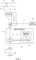
- FIG. 2 is an overall view of an arrester monitor 20 included in the railcar 10 shown in FIG. 1 .
- FIG. 3 is a block diagram including a configuration of the arrester monitor 20 shown in FIG. 2 .
- a large current that flows from the overhead contact line 100 to a power feeding path 13 via the pantograph 11 is transformed into a small current by a current transformer (CT) 14.
- CT current transformer
- a breaker 15, which blocks between the current transformer 14 and main circuitry 40 e.g., VCB: Vacuum Circuit Breaker
- An arrester 16 is located between the breaker 15 and the main circuitry 40.
- a temporarily large current such as a lightning current or surge current occurs, the arrester 16 causes the temporary large current to flow through a carbody 19. Through the carbody 19, the current is diverted to the rails 110.
- the main circuitry 40 is located downstream of the arrester 16 via a main circuitry electrical path 17.
- the current from the pantograph 11 flows to the arrester 16 and the main circuitry 40 via the current transformer 14 and the breaker 15.
- the arrester 16 diverts the current such that it flows from the carbody 19 to the rails 110 via an electrical path 18, thereby protecting the main circuitry 40.
- a current transformer, a breaker, and an arrester that are suitable for the railcar 10 may be used as the current transformer 14, the breaker 15, and the arrester 16.
- the railcar 10 of the present embodiment includes the arrester monitor 20, which is located on the electrical path 18 between the arrester 16 and the carbody 19 and which includes a galvanometer 21.
- the galvanometer 21 measures the value of a current that flows from the arrester 16 to the carbody 19 via the electrical path 18.
- the galvanometer 21 may be, for example, a moving-coil galvanometer. Examples of a current that flows through the electrical path 18 include: a leakage current that flows from the arrester 16 to the carbody 19; a temporary large lightning current; and a surge current that flows at the time of connecting the pantograph 11.
- the galvanometer 21 is electrically connected to a data storage 22 of the arrester monitor 20.
- the value of the current measured by the galvanometer 21 is stored in the data storage 22 in a chronological manner.
- the data storage 22 may be integrated with processing circuitry 23.
- the data storage 22 may include an internal storage medium such as a flash memory or hard disk to store current values measured by the galvanometer 21.
- the arrester monitor 20 measures, on the electrical path 18 and with the galvanometer 21, a current that flows from the arrester 16 to the carbody 19.
- the value of the current measured by the galvanometer 21 is transmitted to the data storage 22 and stored therein in a chronological manner.
- the data storage 22 is electrically connected to the processing circuitry 23.
- the processing circuitry 23 includes a determiner 24. As described below, based on a result of a determination by the determiner 24, a breaker-opening signal is outputted from first output circuitry 25 to control circuitry 27 of the railcar 10. Further, based on a result of a determination by the determiner 24, a signal to prohibit pantograph raising is outputted from second output circuitry 26 to the control circuitry 27 of the railcar 10.
- the processing circuitry 23 includes the determiner 24, an I/O interface, and so forth.
- the determiner 24 includes a processor, a volatile memory, a nonvolatile memory, and so forth.
- An input of a signal indicating a current value stored in the data storage 22 to the processing circuitry 23, a signal output from the first output circuitry 25, a signal output from the second output circuitry 26, and a signal output from the determiner 24 to a display 30 are realized by the I/O interface.
- the determination by the determiner 24 is realized as a result of the processor performing arithmetic processing based on a program stored in the nonvolatile memory by using the volatile memory.
- a control signal to give a command to open the breaker 15 or to give a command to prohibit raising of the pantograph 11 is outputted to the control circuitry 27 of the railcar 10. Also, as described below, based on a result of a determination by the determiner 24, a predetermined deterioration signal is outputted to the display 30, which is, for example, a display monitor of the railcar, to raise an alarm.
- FIG. 4 is a graph showing current/voltage changes when the value of a current measured by the galvanometer 21 of the arrester monitor 20 of FIG. 3 , the current flowing from the arrester 16 to the carbody 19, is in a normal state. The graph also shows the current/voltage changes when the arrester 16 is in a state of failure.
- FIG. 4 is a conceptual diagram showing, for both when the arrester 16 is in a normal state and when the arrester 16 is in a state of failure, changes in a voltage and a current that flow from the arrester 16 to the carbody 19.
- the horizontal axis represents current [A]
- the vertical axis represents voltage [V].
- a slight leakage current occurs in the arrester 16 even when the arrester 16 is in a normal state.
- a leakage current I 1 of the arrester 16 increases little by little until an operation start voltage Vm of the arrester 16 is reached.
- Vm of the arrester 16 When the operation start voltage Vm of the arrester 16 is reached, a large amount of current flows from the arrester 16 to the carbody 19, and as a result, the current value increases significantly.
- the current value at the operation start voltage Vm is an operation start current Im.
- a leakage current I 2 of the arrester 16 increases in proportional to an increase in the voltage.
- the leakage current I 2 increases linearly to a leakage current value In, at which the operation start voltage Vm is reached. Accordingly, in a case where a failure occurs in the arrester 16, the leakage current of the arrester 16 changes from a normal-state leakage current Ia into a failure-state leakage current Ib, i.e., increases very significantly, and as a result, the main circuitry 40 is not sufficiently fed with electric power.
- FIG. 5 is a graph chronologically showing a first measurement example of measuring current values by the galvanometer 21 shown in FIG. 3 .
- the horizontal axis represents time [t]
- the vertical axis represents current [A].
- FIG. 6 is a graph chronologically showing a second measurement example of measuring current values by the galvanometer 21 shown in FIG. 3 .
- the horizontal axis represents time [t]
- the vertical axis represents leakage current [A].
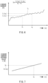
- FIG. 7 is a graph showing, as an average value within a unit time, the current values measured in the second measurement example of FIG. 6 .
- the horizontal axis represents time [t]
- the vertical axis represents leakage current average value I [A].
- the first measurement example of FIG. 5 schematically shows an example in which a large lightning current or a surge current at pantograph raising flows through the carbody 19 via the arrester 16.
- An overcurrent threshold value Is is preset for a large current that flows from the arrester 16 to the carbody 19, and is stored in the processing circuitry 23.
- the overcurrent threshold value Is is greater than the operation start current Im of the arrester 16, and is set to the value of an overcurrent that affects the life of the arrester 16.
- the example in FIG. 5 shows a record of three times occurrence (Is 1 , Is 2 , Is 3 ) of a current value change pattern in which the current value measured by the galvanometer 21 exceeds the predetermined overcurrent threshold value Is and then drops below the overcurrent threshold value Is.
- the processing circuitry 23 determines whether or not the current value change pattern, in which the current value measured by the galvanometer 21 exceeds the overcurrent threshold value Is and then drops below the overcurrent threshold value Is, has occurred more than a predetermined number of times. In a case where a result of the determination indicates that the current value change pattern has occurred more than the predetermined number of times, it is determined that the arrester 16 is in a state of deterioration.
- the predetermined number of times may be set based on, for example, the size of the arrester 16.
- the second measurement example of FIG. 6 schematically shows an example in which due to aging deterioration of the arrester 16, the leakage current I 1 flowing through the carbody 19 via the arrester 16 increases.
- the leakage current I 1 in a small amount is flowing from the arrester 16 to the carbody 19.
- the leakage current I 1 gradually increases due to, for example, deterioration of the arrester 16.
- FIG. 6 shows an example in which the leakage current I 1 flowing from the arrester 16 to the carbody 19 changes due to operations of the railcar 10, and increases in accordance with elapse of time.
- Such chronological changes in the leakage current I 1 may be defined as, for example, an average value Ix within a predetermined time from a leakage current I 1 (x 1 ) at a time x 1 to a leakage current I 1 (x 2 ) at a time x 2 .
- the average value Ix of the leakage current I 1 within the predetermined time shown in the graph of FIG. 6 may be defined as a leakage current average value Ix(x 2 ) at the time x 2 .
- the leakage current average value Ix(x 2 ) shown in FIG. 7 is greater than a predetermined deterioration threshold value, it can be determined that the arrester 16 is in a state of deterioration.
- the average value Ix within the predetermined time shown in FIG. 6 as the value at the time x 2 , which is the end of the predetermined time, whether or not the arrester 16 is in a state of deterioration can be determined, the next time the arrester monitor 20 is powered on, based on the average value Ix of the leakage current I 1 at a point immediately before the previous powering off of the arrester monitor 20.
- FIG. 8 is a graph showing one example where the deterioration level of the arrester 16 is divided by multiple deterioration threshold values.
- the horizontal axis represents time [t]
- the vertical axis represents leakage current [A].
- FIG. 8 shows a case where the voltage that changes while the railcar 10 is operating is assumed to be constant.
- the leakage current I 1 of the arrester 16 increases as the deterioration of the arrester 16 progresses in accordance with elapse of time.
- the leakage current I 1 is not uniform, and is affected by various conditions (e.g., voltage changes, usage time of the arrester, etc.). Therefore, the slope of the leakage current I 1 , changes in the leakage current I 1 , etc., are not limited to those in the illustrated example.
- FIG. 9 is a graph showing one example of setting multiple deterioration levels based on current values in relation to the current/voltage changes shown in FIG. 4 .
- the horizontal axis represents current [A]
- the vertical axis represents voltage value [V].
- FIG. 9 shows a part of FIG. 4 in an enlarged manner, such that a part where the deterioration levels are set is illustrated in an exaggerated manner.
- multiple deterioration levels of the arrester 16 are set by leakage current values within an overhead contact line voltage range.
- the leakage current I 1 increases little by little in accordance with increase in the voltage, and when the operation start voltage Vm is reached, the leakage current I 1 increases significantly from the operation start current Im.
- a line that indicates changes in the leakage current I 1 until the operation start voltage Vm and the operation start current Im are reached is approximated by a straight line, and the straight line is defined as a first level determination line I 10 .
- the first level determination line I 10 is shifted in a parallel direction so as to coincide with an intersection point O 1 of the operation start voltage Vm and the operation start current Im.
- the current value indicated by the first level determination line I 10 serves as a deterioration threshold value.
- the current value indicated by the first level determination line I 10 is the first deterioration threshold value D 1 .
- Values greater than the first deterioration threshold value D 1 are defined to fall within the first deterioration level E 2 .
- the first level determination line I 10 is, for example, a straight line that approximates the leakage current I 1 in a normal state, and the first level determination line I 10 is shifted to the operation start current Im at which the current value is higher.
- the current value indicated by the first deterioration threshold value D 1 is slightly higher than the leakage current I 1 in a normal state.
- the current value indicated by the first deterioration threshold value D 1 increases in accordance with increase in the voltage.
- the rate of increase in the first deterioration threshold value D 1 in accordance with increase in the voltage is similar to the rate of increase in the leakage current I 1 in a normal state in accordance with increase in the voltage.
- a second level determination line I 20 is drawn to set another deterioration level.
- a line that connects between an intersection point Oz and an intersection point O 3 is set as the second level determination line I 20 .
- the intersection point Oz is an intersection point of the lower limit of the overhead contact line voltage range and the first level determination line I 10 .
- the intersection point O 3 is an intersection point of an arrester continuous operating voltage Vn and the operation start current Im.
- the overhead contact line voltage range is the voltage range of the overhead contact line, and changes while the railcar 10 is operating.
- the arrester continuous operating voltage Vn is a voltage that can be continuously applied between both terminals of the arrester 16 (JIS E 5010), and is set in accordance with the arrester 16.
- a current value indicated by the second level determination line I 20 is the second deterioration threshold value D 2 , and values exceeding the second deterioration threshold value D 2 are defined to fall within the second deterioration level E 3 .
- the second deterioration threshold value D 2 is set such that the current value indicated thereby increases in accordance with increase in the voltage.
- the rate of increase in the second deterioration threshold value in accordance with increase in the voltage is greater than the rate of increase in the first deterioration threshold value in accordance with increase in the voltage.
- the second deterioration threshold value D 2 at the lower limit of the overhead contact line voltage range is the current value at the intersection point Oz of the first level determination line I 10 and the lower limit of the overhead contact line voltage range.
- the second level determination line I 20 may intersect the lower limit of the overhead contact line voltage range at a current value that is less than or greater than the intersection point Oz.
- the arrester monitor 20 it is determined whether or not a leakage current value measured by the galvanometer 21 is greater than the first deterioration threshold value D 1 of the first level determination line I 10 , and it is also determined whether or not the leakage current value measured by the galvanometer 21 is greater than the first deterioration threshold value D 1 of the first level determination line I 10 and the second deterioration threshold value D 2 of the second level determination line I 20 .
- These determinations are performed within the overhead contact line voltage range. In the present embodiment, based on results of these determinations, one of the following is performed: raising "no alarm”; raising a "warning" alarm; and raising a "failure" alarm.
- intersection point of the second level determination line I 20 and the lower limit of the overhead contact line voltage range may be set to a current value that is greater than the intersection point Oz of the first level determination line I 10 and the lower limit of the overhead contact line voltage range, so that the first deterioration level E 2 , for which a "warning" alarm is raised, exists at the lower limit of the overhead contact line voltage range.
- the intersection point of the second level determination line I 20 and the lower limit of the overhead contact line voltage range may be set to a current value that is less than the intersection point Oz. This makes it possible to raise a "failure" alarm for a less leakage current.
- the state of deterioration of the arrester 16 is divided into multiple deterioration levels corresponding to respective magnitudes of the leakage current I 1 .
- a deterioration signal can be made different for each deterioration level. Making the deterioration signal different for each deterioration level of the arrester 16 makes it possible to perform, for example, replacement work of the arrester 16 in accordance with a prepared plan.
- the example has been described, in which the first deterioration threshold value D 1 and the second deterioration threshold value D 2 are set, and based thereon two-stage deterioration level determination is performed, in which the alarms are raised in two stages, i.e., "warning" and "failure", from the state of "no alarm".
- the deterioration level determination may be performed in an alternative manner, in which a "failure" alarm is raised from the state of "no alarm”.
- more than two deterioration levels may be set.
- FIG. 10 is a first flowchart showing a flow of operations of the arrester monitor 20 while the railcar 10 is operating. The following description is given by using the reference signs shown in FIG. 3 .
- a current flowing through the current transformer 14 is an overcurrent (S1).
- the breaker 15 is opened (S6), and the flow ends.
- the arrester 16 is in a healthy state (S2).
- the arrester 16 is determined to be in a healthy state, the flow ends.
- FIG. 11 is a second flowchart showing a flow of operations of the arrester monitor 20 at the time of powering on the railcar 10.
- a flow of operations of the railcar 10 is shown on the left side, and the flow of operations of the arrester monitor 20 is shown on the right side.
- the following description is given by using the reference signs shown in FIG. 3 .
- the arrester monitor 20 determines whether or not the arrester 16 is in a healthy state (S12). In a case where the arrester 16 is determined to be in a healthy state, a pantograph-raising permission is given (S13). In this manner, the permission to raise the pantograph 11 is given for the arrester 16. Then, the pantograph 11 is pressed against the overhead contact line, and a breaker-closing permission is given (S14). Thereafter, it is determined whether or not a current entering the current transformer 14 is an overcurrent (S15).
- the flow ends.
- the breaker 15 is opened (S20), and the flow ends. After the breaker 15 is opened, the breaker 15 is brought into a closing-prohibited state, and then even if an operation to close the breaker 15 is erroneously performed, the breaker 15 will not be closed.
- a signal to prohibit pantograph raising is outputted (S19), and the breaker 15 is opened (S20). Then, the flow ends.
- the signal to prohibit pantograph raising includes a signal to disconnect pantograph-raising control circuitry that is included in the control circuitry 27 of the railcar 10.
- opening the breaker 15 includes outputting a signal to interrupt breaker-closing control circuitry that is included in the control circuitry 27 of the railcar 10. After the signal to prohibit pantograph raising is outputted, even if an operation to raise the pantograph 11 is performed erroneously, the pantograph 11 will not be raised. Also, after the breaker 15 is opened, the breaker 15 is brought into a closing-prohibited state, and then even if an operation to close the breaker 15 is erroneously performed, the breaker 15 will not be closed.
- a signal to display "FAILURE" is outputted to the display 30 (S21). Thereafter, a signal to prohibit pantograph raising is outputted (S19), and the breaker 15 is opened (S20). Then, the flow ends. After the signal to prohibit pantograph raising is outputted, even if an operation to raise the pantograph 11 is performed erroneously, the pantograph 11 will not be raised. Also, after the breaker 15 is opened, the breaker 15 is brought into a closing-prohibited state, and then even if an operation to close the breaker 15 is erroneously performed, the breaker 15 will not be closed.
- the arrester monitor 20 determines whether or not the arrester 16 is in a state of deterioration, and in a case where the arrester 16 is in a state of deterioration, a "warning" or “failure” alarm is raised, which makes early-stage replacement of the arrester 16 possible.
- FIG. 12 is a third flowchart showing a flow of operations of the arrester monitor 20 at the time of powering off the railcar 10. Also in the third flowchart, a flow of operations of the railcar 10 is shown on the left side, and the flow of operations of the arrester monitor 20 is shown on the right side.
- the flow starts, and an opening command is given to the breaker 15 (S30).
- the arrester monitor 20 performs arrester state storing to store the state of the arrester 16 before the powering off (S31).
- the arrester state storing may be, for example, as shown in FIG. 7 , storing the average value Ix within the predetermined time from the time x 1 to the time x 2 as a leakage current average value Ix(x 2 ) at the time of powering off.
- the arrester monitor 20 is powered off (S32).
- a command to lower the pantograph 11 is given to the railcar 10 (S33), and the control power of the railcar 10 is turned off (S34). Then, the flow ends.
- the arrester state storing by the arrester monitor 20 at the time of powering off the railcar 10 is the storing of the leakage current at the time x 2 when powering off. Therefore, the final leakage current average value Ix(x 2 ) when powering off the arrester 16 at the time of powering off the railcar 10 can be used as a basis for the determination in step (S12) shown in FIG. 11 .
- the state of deterioration of the arrester 16 may be determined and an alarm may be raised at the time of powering off the arrester monitor 20. In a case where an alarm is raised at the time of ending the operation of the railcar 10, and the alarm indicates that it is necessary to replace the arrester 16, the arrester 16 can be replaced before the start of the next operation of the railcar 10. In a case where an alarm is raised before the start of operating the railcar 10, the state of the arrester 16 can be checked based on the alarm before the start of operating the railcar 10.
- the alarm can be displayed as a message. For example, the displayed message may be: "The arrester is in a state of deterioration. Please replace the arrester at the next inspection of the railcar.” As another example, the displayed message may be: "The arrester is in a state of failure. Please replace the arrester.”
- the alarm may be raised with use of light.
- FIG. 13 illustrates a display example of "WARNING" on a display monitor screen as shown in FIG. 10 and FIG. 11 .
- FIG. 14 illustrates a display example of "FAILURE" on the display monitor screen as shown in FIG. 10 and FIG. 11 .
- the present embodiment describes examples in which the state of deterioration of the arrester 16 is notified on the display monitor.
- a message “ARRESTER: WARNING: CAR NO. ##” is displayed on the display 30, which can be checked at the driver's seat of the railcar 10. In this manner, information indicating on which car the arrester 16 is in a state of deterioration can be displayed. For example, the display can be shown in yellow to draw attention.
- a message “ARRESTER: FAILURE: CAR NO. ##” is displayed on the display 30, which can be checked at the driver's seat of the railcar 10. In this manner, information indicating on which car the arrester 16 is in a state of failure can be displayed. For example, the display can be shown in red to draw more attention.
- an alarm is raised by using the display 30, which is, for example, a display monitor of the railcar.
- an alarm can be raised by, for example, a sound or a warning lamp.
- the arrester 16 can be replaced before the start of the next operation of the railcar 10.
- the state of the arrester 16 can be checked based on the alarm before the start of operating the railcar 10.
- the alarm can be displayed as a message.
- the displayed message may be: "The arrester is in a state of deterioration. Please replace the arrester at the next inspection of the railcar.”
- the displayed message may be: "The arrester is in a state of failure. Please replace the arrester.”
- the railcar 10 includes eight cars.
- the number of cars included in the railcar 10 are not limited to those described in the above embodiment.
- circuitry or processing circuitry which includes general purpose processors, special purpose processors, integrated circuits, ASICs ("Application Specific Integrated Circuits"), conventional circuitry and/or combinations thereof which are configured or programmed to perform the disclosed functionality.
- Processors are considered processing circuitry or circuitry as they include transistors and other circuitry therein.
- the circuitry, units, or means are hardware that carry out or are programmed to perform the recited functionality.
- the hardware may be any hardware disclosed herein or otherwise known which is programmed or configured to carry out the recited functionality.
- the hardware is a processor which may be considered a type of circuitry
- the circuitry, means, or units are a combination of hardware and software, the software being used to configure the hardware and/or processor.
- the value of a current that flows from the arrester 16 to the carbody 19 via the electrical path 18 is measured by the galvanometer 21, and the measured value of the current can be stored in the data storage 22 as history data in a chronological manner.
- the processing circuitry 23 determines that the arrester 16 is in a state of deterioration and outputs a predetermined deterioration signal in a case where an average value of the current within a predetermined unit time is greater than a predetermined deterioration threshold value. Accordingly, the fact that the arrester of the railcar 10 is in a state of deterioration can be known from the deterioration signal.
- the processing circuitry may determine that the arrester is in the state of deterioration in a case where, in the history data, a number of occurrences of a current value change pattern is greater than a predetermined number of times, the current value change pattern being a pattern in which the value of the current exceeds a predetermined overcurrent threshold value and then drops below the overcurrent threshold value.
- the deterioration signal may include a signal to display a warning on a display. According to this configuration, the state of deterioration of the arrester can be displayed on the display for external notification purposes.
- the deterioration signal may include a signal to open a breaker that is interposed in a power feeding path to the arrester.
- the breaker can be opened in accordance with the state of deterioration of the arrester to prevent a current from flowing to the arrester.
- the deterioration signal may include a signal to prohibit raising of a pantograph of the railcar. According to this configuration, pantograph raising can be prohibited in accordance with the state of deterioration of the arrester to prevent entry of a current from the overhead contact line.
- the state of deterioration may be divided into multiple deterioration levels corresponding to respective deterioration degrees of the arrester, and the processing circuitry may make the deterioration signal different in accordance with to which one of the multiple deterioration levels the chronological change in the history data corresponds.
- a replacement work timing for the arrester can be planned in accordance with the deterioration signal, which is different for each deterioration level of the arrester.
- a railcar including the arrester monitor according to any one of the above-described modes is capable of properly determining, with the arrester monitor, that an arrester included in the railcar is in a state of deterioration.
Landscapes
- Engineering & Computer Science (AREA)
- Mechanical Engineering (AREA)
- General Physics & Mathematics (AREA)
- Physics & Mathematics (AREA)
- Health & Medical Sciences (AREA)
- Biomedical Technology (AREA)
- General Health & Medical Sciences (AREA)
- Power Engineering (AREA)
- Life Sciences & Earth Sciences (AREA)
- Sustainable Development (AREA)
- Sustainable Energy (AREA)
- Transportation (AREA)
- Electric Propulsion And Braking For Vehicles (AREA)
- Testing Electric Properties And Detecting Electric Faults (AREA)
Abstract
Description
- The present disclosure relates to an arrester monitor and a railcar including the same.
- Conventionally, a railcar includes an arrester. When a large current flows from an overhead contact line, the arrester diverts the large current such that it flows from the carbody to the rails, thereby preventing the large current from flowing through main circuitry. When the large current flows through an electrical path of the arrester, the internal resistance value thereof drops temporarily to divert the large current to the carbody. The large current is caused by lightning or by a surge that occurs when raising/lowering the pantograph. The arrester protects devices that are connected to the main circuitry from the large current. Usually, the arrester is replaced at each specified period.
- One example of conventional art relating to this type of arrester is an arrester leakage current detector that is installed at, for example, a transformer substation (see
Patent Literature 1, for example). The arrester leakage current detector includes a total leakage current measurer and a total leakage current storage. The arrester leakage current detector further includes: a higher harmonic remover to remove higher harmonics in a total leakage current; a total leakage current waveform adjuster; a total leakage current difference detector; and a resistance component current detector to detect a resistance component current in the total leakage current. With this configuration, the resistance component current of the arrester is obtained, and based on the obtained resistance component current, deterioration of the arrester is detected at an early stage. - PTL 1:
Japanese Patent No. 6616193 - As described above, the arrester included in the railcar diverts the large current to the carbody to prevent the large current from flowing through the main circuitry. However, there is a case where the arrester deteriorates more than expected even within the aforementioned specified period. If the arrester deteriorates, the leakage current that flows from the arrester to the carbody increases, and consequently, the amount of electric power transmitted to the main circuitry decreases.
- The above-described conventional art relates to an arrester installed at a transformer substation or the like, and monitors deterioration of the arrester by measuring the total leakage current of the arrester at a predetermined time. Therefore, this conventional art is not applicable to monitoring the deterioration of an arrester included in a railcar that is operated at different times in accordance with an operation schedule or the like.
- In view of the above, an object of one aspect of the present disclosure is to provide an arrester monitor that is capable of monitoring deterioration of an arrester included in a railcar based on the value of a current that flows from the arrester to a carbody of the railcar, and to provide a railcar including the arrester monitor.
- In order to achieve the above object, an arrester monitor according to one aspect of the present disclosure includes: a galvanometer that measures, on an electrical path between an arrester of a railcar and a carbody of the railcar, a value of a current that flows from the arrester to a grounded part the carbody; a data storage that stores the value of the current, which has been measured by the galvanometer, as history data in a chronological manner; and processing circuitry configured to determine, based on a chronological change in the history data stored in the data storage, that the arrester is in a state of deterioration and output a predetermined deterioration signal in a case where an average value of the current within a predetermined unit time is greater than a predetermined deterioration threshold value.
- One aspect of the present disclosure makes it possible to provide an arrester monitor capable of monitoring deterioration of an arrester included in a railcar based on the value of a current that flows from the arrester to a carbody of the railcar.
-
-
FIG. 1 is a side view schematically showing a railcar according to one embodiment of the present disclosure. -
FIG. 2 is an overall view of an arrester monitor included in the railcar shown inFIG. 1 . -
FIG. 3 is a block diagram including a configuration of the arrester monitor shown inFIG. 2 . -
FIG. 4 is a graph showing current/voltage changes when the value of a current measured by a galvanometer of the arrester monitor ofFIG. 3 , the current flowing from an arrester to a carbody, is in a normal state, the graph also showing the current/voltage changes when the arrester is in a state of failure. -
FIG. 5 is a graph chronologically showing a first measurement example of measuring current values by the galvanometer shown inFIG. 3 . -
FIG. 6 is a graph chronologically showing a second measurement example of measuring current values by the galvanometer shown inFIG. 3 . -
FIG. 7 is a graph showing, as an average value within a unit time, the current values measured in the second measurement example ofFIG. 6 . -
FIG. 8 is a graph showing one example where the deterioration level of the arrester is divided by multiple deterioration threshold values. -
FIG. 9 is a graph showing one example of setting multiple deterioration levels based on current values in relation to the current/voltage changes shown inFIG. 4 . -
FIG. 10 is a first flowchart showing a flow of operations of the arrester monitor while the railcar is operating. -
FIG. 11 is a second flowchart showing a flow of operations of the arrester monitor at the time of powering on the railcar. -
FIG. 12 is a third flowchart showing a flow of operations of the arrester monitor at the time of powering off the railcar. -
FIG. 13 illustrates a display example of "WARNING" on a display monitor screen as shown inFIG. 10 andFIG. 11 . -
FIG. 14 illustrates a display example of "FAILURE" on the display monitor screen as shown inFIG. 10 andFIG. 11 . - Hereinafter, one embodiment of the present disclosure is described. The embodiment described below is merely one example, in which the description is given by taking a high-speed railcar that travels at a relatively high speed as an example. The forward-backward direction referred to in the description and the claims coincides with a traveling direction of a
railcar 10 shown inFIG. 1 , which is a side view of therailcar 10. -
FIG. 1 is a side view schematically showing therailcar 10 according to one embodiment. Therailcar 10 in this embodiment includes eight cars as one example. Therailcar 10 is a train set in whichcars 1 to 8 are coupled to one another. In this example, apantograph 11 is located on the roof of each of thecar 3 and thecar 6 of therailcar 10. Thepantograph 11 is in contact with anoverhead contact line 100 with a constant pressure. Therailcar 10 travels onrails 110 bywheels 12. The present embodiment describes therailcar 10 including eight cars as one example. However, the number of cars included in therailcar 10, the arrangement of the pantographs on therailcar 10, etc., are not limited to those described in this example. -
FIG. 2 is an overall view of anarrester monitor 20 included in therailcar 10 shown inFIG. 1 .FIG. 3 is a block diagram including a configuration of thearrester monitor 20 shown inFIG. 2 . - As shown in
FIG. 2 , in the present embodiment, a large current that flows from theoverhead contact line 100 to apower feeding path 13 via thepantograph 11 is transformed into a small current by a current transformer (CT) 14. Abreaker 15, which blocks between thecurrent transformer 14 and main circuitry 40 (e.g., VCB: Vacuum Circuit Breaker), is located downstream of thecurrent transformer 14. Anarrester 16 is located between thebreaker 15 and themain circuitry 40. When a temporarily large current such as a lightning current or surge current occurs, thearrester 16 causes the temporary large current to flow through acarbody 19. Through thecarbody 19, the current is diverted to therails 110. Themain circuitry 40 is located downstream of thearrester 16 via a main circuitryelectrical path 17. According to therailcar 10 of the present embodiment, the current from thepantograph 11 flows to thearrester 16 and themain circuitry 40 via thecurrent transformer 14 and thebreaker 15. In a case where the voltage value of the current that flows from thebreaker 15 to themain circuitry 40 exceeds a threshold value, thearrester 16 diverts the current such that it flows from thecarbody 19 to therails 110 via anelectrical path 18, thereby protecting themain circuitry 40. A current transformer, a breaker, and an arrester that are suitable for therailcar 10 may be used as thecurrent transformer 14, thebreaker 15, and thearrester 16. - The
railcar 10 of the present embodiment includes thearrester monitor 20, which is located on theelectrical path 18 between thearrester 16 and the carbody 19 and which includes agalvanometer 21. Thegalvanometer 21 measures the value of a current that flows from thearrester 16 to thecarbody 19 via theelectrical path 18. Thegalvanometer 21 may be, for example, a moving-coil galvanometer. Examples of a current that flows through theelectrical path 18 include: a leakage current that flows from thearrester 16 to thecarbody 19; a temporary large lightning current; and a surge current that flows at the time of connecting thepantograph 11. Thegalvanometer 21 is electrically connected to adata storage 22 of thearrester monitor 20. The value of the current measured by thegalvanometer 21 is stored in thedata storage 22 in a chronological manner. Thedata storage 22 may be integrated withprocessing circuitry 23. Thedata storage 22 may include an internal storage medium such as a flash memory or hard disk to store current values measured by thegalvanometer 21. - As shown in
FIG. 3 , the arrester monitor 20 measures, on theelectrical path 18 and with thegalvanometer 21, a current that flows from thearrester 16 to thecarbody 19. The value of the current measured by thegalvanometer 21 is transmitted to thedata storage 22 and stored therein in a chronological manner. Thedata storage 22 is electrically connected to theprocessing circuitry 23. Theprocessing circuitry 23 includes adeterminer 24. As described below, based on a result of a determination by thedeterminer 24, a breaker-opening signal is outputted fromfirst output circuitry 25 to controlcircuitry 27 of therailcar 10. Further, based on a result of a determination by thedeterminer 24, a signal to prohibit pantograph raising is outputted fromsecond output circuitry 26 to thecontrol circuitry 27 of therailcar 10. - The
processing circuitry 23 includes thedeterminer 24, an I/O interface, and so forth. Thedeterminer 24 includes a processor, a volatile memory, a nonvolatile memory, and so forth. An input of a signal indicating a current value stored in thedata storage 22 to theprocessing circuitry 23, a signal output from thefirst output circuitry 25, a signal output from thesecond output circuitry 26, and a signal output from thedeterminer 24 to adisplay 30 are realized by the I/O interface. The determination by thedeterminer 24 is realized as a result of the processor performing arithmetic processing based on a program stored in the nonvolatile memory by using the volatile memory. - In the present embodiment, as described below, based on a result of a determination by the
determiner 24, a control signal to give a command to open thebreaker 15 or to give a command to prohibit raising of thepantograph 11 is outputted to thecontrol circuitry 27 of therailcar 10. Also, as described below, based on a result of a determination by thedeterminer 24, a predetermined deterioration signal is outputted to thedisplay 30, which is, for example, a display monitor of the railcar, to raise an alarm. -
FIG. 4 is a graph showing current/voltage changes when the value of a current measured by thegalvanometer 21 of the arrester monitor 20 ofFIG. 3 , the current flowing from thearrester 16 to thecarbody 19, is in a normal state. The graph also shows the current/voltage changes when thearrester 16 is in a state of failure.FIG. 4 is a conceptual diagram showing, for both when thearrester 16 is in a normal state and when thearrester 16 is in a state of failure, changes in a voltage and a current that flow from thearrester 16 to thecarbody 19. InFIG. 4 , the horizontal axis represents current [A], and the vertical axis represents voltage [V]. - A slight leakage current occurs in the
arrester 16 even when thearrester 16 is in a normal state. A leakage current I1 of thearrester 16 increases little by little until an operation start voltage Vm of thearrester 16 is reached. When the operation start voltage Vm of thearrester 16 is reached, a large amount of current flows from thearrester 16 to thecarbody 19, and as a result, the current value increases significantly. The current value at the operation start voltage Vm is an operation start current Im. Thus, even when thearrester 16 is in a normal state, the leakage current I1 occurs, and the leakage current I1 increases little by little until the operation start current Im is reached, but after the operation start current Im is exceeded, the leakage current I1 increases significantly. - On the other hand, in a case where the
arrester 16 is in a state of failure, a leakage current I2 of thearrester 16 increases in proportional to an increase in the voltage. The leakage current I2 increases linearly to a leakage current value In, at which the operation start voltage Vm is reached. Accordingly, in a case where a failure occurs in thearrester 16, the leakage current of thearrester 16 changes from a normal-state leakage current Ia into a failure-state leakage current Ib, i.e., increases very significantly, and as a result, themain circuitry 40 is not sufficiently fed with electric power. -
FIG. 5 is a graph chronologically showing a first measurement example of measuring current values by thegalvanometer 21 shown inFIG. 3 . InFIG. 5 , the horizontal axis represents time [t], and the vertical axis represents current [A].FIG. 6 is a graph chronologically showing a second measurement example of measuring current values by thegalvanometer 21 shown inFIG. 3 . InFIG. 6 , the horizontal axis represents time [t], and the vertical axis represents leakage current [A].FIG. 7 is a graph showing, as an average value within a unit time, the current values measured in the second measurement example ofFIG. 6 . InFIG. 7 , the horizontal axis represents time [t], and the vertical axis represents leakage current average value I [A]. - The first measurement example of
FIG. 5 schematically shows an example in which a large lightning current or a surge current at pantograph raising flows through thecarbody 19 via thearrester 16. An overcurrent threshold value Is is preset for a large current that flows from thearrester 16 to thecarbody 19, and is stored in theprocessing circuitry 23. The overcurrent threshold value Is is greater than the operation start current Im of thearrester 16, and is set to the value of an overcurrent that affects the life of thearrester 16. The example inFIG. 5 shows a record of three times occurrence (Is1, Is2, Is3) of a current value change pattern in which the current value measured by thegalvanometer 21 exceeds the predetermined overcurrent threshold value Is and then drops below the overcurrent threshold value Is. Theprocessing circuitry 23 determines whether or not the current value change pattern, in which the current value measured by thegalvanometer 21 exceeds the overcurrent threshold value Is and then drops below the overcurrent threshold value Is, has occurred more than a predetermined number of times. In a case where a result of the determination indicates that the current value change pattern has occurred more than the predetermined number of times, it is determined that thearrester 16 is in a state of deterioration. The predetermined number of times may be set based on, for example, the size of thearrester 16. - The second measurement example of
FIG. 6 schematically shows an example in which due to aging deterioration of thearrester 16, the leakage current I1 flowing through thecarbody 19 via thearrester 16 increases. The leakage current I1 in a small amount is flowing from thearrester 16 to thecarbody 19. The leakage current I1 gradually increases due to, for example, deterioration of thearrester 16.FIG. 6 shows an example in which the leakage current I1 flowing from thearrester 16 to the carbody 19 changes due to operations of therailcar 10, and increases in accordance with elapse of time. Such chronological changes in the leakage current I1 may be defined as, for example, an average value Ix within a predetermined time from a leakage current I1(x1) at a time x1 to a leakage current I1(x2) at a time x2. - Then, as shown in
FIG. 7 , the average value Ix of the leakage current I1 within the predetermined time shown in the graph ofFIG. 6 may be defined as a leakage current average value Ix(x2) at the time x2. In a case where the leakage current average value Ix(x2) shown inFIG. 7 is greater than a predetermined deterioration threshold value, it can be determined that thearrester 16 is in a state of deterioration. - Further, as shown in
FIG. 7 , by defining the average value Ix within the predetermined time shown inFIG. 6 as the value at the time x2, which is the end of the predetermined time, whether or not thearrester 16 is in a state of deterioration can be determined, the next time the arrester monitor 20 is powered on, based on the average value Ix of the leakage current I1 at a point immediately before the previous powering off of thearrester monitor 20. -
FIG. 8 is a graph showing one example where the deterioration level of thearrester 16 is divided by multiple deterioration threshold values. InFIG. 8 , the horizontal axis represents time [t], and the vertical axis represents leakage current [A].FIG. 8 shows a case where the voltage that changes while therailcar 10 is operating is assumed to be constant. The leakage current I1 of thearrester 16 increases as the deterioration of thearrester 16 progresses in accordance with elapse of time. When the leakage current I1, which increases in accordance with a progress in the deterioration of thearrester 16, increases from a normal level E1 to have exceeded a first deterioration threshold value D1, it is determined that a first deterioration level E2 has been reached. When the leakage current I1 increases from the first deterioration level E2 to have exceeded a second deterioration threshold value D2, it is determined that a second deterioration level E3 has been reached. In the present embodiment, when the first deterioration level E2 has been reached, a "warning" alarm is raised, and when the second deterioration level E3 has been reached, a "failure" alarm is raised. The leakage current I1 shown inFIG. 8 is one example illustrated in relation to the constant voltage, and this example conceptually shows the leakage current I1, which increases in accordance with a progress in the deterioration of thearrester 16. The leakage current I1 is not uniform, and is affected by various conditions (e.g., voltage changes, usage time of the arrester, etc.). Therefore, the slope of the leakage current I1, changes in the leakage current I1, etc., are not limited to those in the illustrated example. -
FIG. 9 is a graph showing one example of setting multiple deterioration levels based on current values in relation to the current/voltage changes shown inFIG. 4 . InFIG. 9 , the horizontal axis represents current [A], and the vertical axis represents voltage value [V].FIG. 9 shows a part ofFIG. 4 in an enlarged manner, such that a part where the deterioration levels are set is illustrated in an exaggerated manner. In this example, multiple deterioration levels of thearrester 16 are set by leakage current values within an overhead contact line voltage range. - As described above, when the
arrester 16 is in a normal state, the leakage current I1 increases little by little in accordance with increase in the voltage, and when the operation start voltage Vm is reached, the leakage current I1 increases significantly from the operation start current Im. InFIG. 9 , a line that indicates changes in the leakage current I1 until the operation start voltage Vm and the operation start current Im are reached is approximated by a straight line, and the straight line is defined as a first level determination line I10. The first level determination line I10 is shifted in a parallel direction so as to coincide with an intersection point O1 of the operation start voltage Vm and the operation start current Im. The current value indicated by the first level determination line I10 serves as a deterioration threshold value. In this example, multiple deterioration levels are set, and the current value indicated by the first level determination line I10 is the first deterioration threshold value D1. Values greater than the first deterioration threshold value D1 are defined to fall within the first deterioration level E2. The first level determination line I10 is, for example, a straight line that approximates the leakage current I1 in a normal state, and the first level determination line I10 is shifted to the operation start current Im at which the current value is higher. The current value indicated by the first deterioration threshold value D1 is slightly higher than the leakage current I1 in a normal state. The current value indicated by the first deterioration threshold value D1 increases in accordance with increase in the voltage. The rate of increase in the first deterioration threshold value D1 in accordance with increase in the voltage is similar to the rate of increase in the leakage current I1 in a normal state in accordance with increase in the voltage. - In
FIG. 9 , a second level determination line I20 is drawn to set another deterioration level. A line that connects between an intersection point Oz and an intersection point O3 is set as the second level determination line I20. The intersection point Oz is an intersection point of the lower limit of the overhead contact line voltage range and the first level determination line I10. The intersection point O3 is an intersection point of an arrester continuous operating voltage Vn and the operation start current Im. The overhead contact line voltage range is the voltage range of the overhead contact line, and changes while therailcar 10 is operating. The arrester continuous operating voltage Vn is a voltage that can be continuously applied between both terminals of the arrester 16 (JIS E 5010), and is set in accordance with thearrester 16. - A current value indicated by the second level determination line I20 is the second deterioration threshold value D2, and values exceeding the second deterioration threshold value D2 are defined to fall within the second deterioration level E3. The second deterioration threshold value D2 is set such that the current value indicated thereby increases in accordance with increase in the voltage. In this example, the rate of increase in the second deterioration threshold value in accordance with increase in the voltage is greater than the rate of increase in the first deterioration threshold value in accordance with increase in the voltage. In
FIG. 9 , the second deterioration threshold value D2 at the lower limit of the overhead contact line voltage range is the current value at the intersection point Oz of the first level determination line I10 and the lower limit of the overhead contact line voltage range. Alternatively, the second level determination line I20 may intersect the lower limit of the overhead contact line voltage range at a current value that is less than or greater than the intersection point Oz. - In the present embodiment, in the
arrester monitor 20, it is determined whether or not a leakage current value measured by thegalvanometer 21 is greater than the first deterioration threshold value D1 of the first level determination line I10, and it is also determined whether or not the leakage current value measured by thegalvanometer 21 is greater than the first deterioration threshold value D1 of the first level determination line I10 and the second deterioration threshold value D2 of the second level determination line I20. These determinations are performed within the overhead contact line voltage range. In the present embodiment, based on results of these determinations, one of the following is performed: raising "no alarm"; raising a "warning" alarm; and raising a "failure" alarm. - Based on chronological changes in the leakage current measured by the
galvanometer 21, in a case where the leakage current value is within the range of the normal level E1, which is less than the first deterioration threshold value D1, it is determined that the leakage current I1 is within its normal range, and "no alarm" is raised. - Based on chronological changes in the leakage current measured by the
galvanometer 21, in a case where the leakage current value is within the range of the first deterioration level E2, which is greater than the first deterioration threshold value D1 but less than the second deterioration threshold value D2, it means that the leakage current I1 has slightly increased. Therefore, a "warning" alarm is raised. - Based on chronological changes in the leakage current measured by the
galvanometer 21, in a case where the leakage current value is within the range of the second deterioration level E3, which is greater than the second deterioration threshold value D2, it means that the leakage current I1 has exceeded the predetermined range. Therefore, a "failure" alarm is raised. In the example shown inFIG. 9 , at the lower limit of the overhead contact line voltage range, the next level after the normal level E1 for which "no alarm" is raised is the second deterioration level E3 for which a "failure" alarm is raised. However, as mentioned above, the intersection point of the second level determination line I20 and the lower limit of the overhead contact line voltage range may be set to a current value that is greater than the intersection point Oz of the first level determination line I10 and the lower limit of the overhead contact line voltage range, so that the first deterioration level E2, for which a "warning" alarm is raised, exists at the lower limit of the overhead contact line voltage range. Alternatively, the intersection point of the second level determination line I20 and the lower limit of the overhead contact line voltage range may be set to a current value that is less than the intersection point Oz. This makes it possible to raise a "failure" alarm for a less leakage current. - Thus, the state of deterioration of the
arrester 16 is divided into multiple deterioration levels corresponding to respective magnitudes of the leakage current I1. By the division into the multiple deterioration levels, a deterioration signal can be made different for each deterioration level. Making the deterioration signal different for each deterioration level of thearrester 16 makes it possible to perform, for example, replacement work of thearrester 16 in accordance with a prepared plan. - In the present embodiment, the example has been described, in which the first deterioration threshold value D1 and the second deterioration threshold value D2 are set, and based thereon two-stage deterioration level determination is performed, in which the alarms are raised in two stages, i.e., "warning" and "failure", from the state of "no alarm". However, the deterioration level determination may be performed in an alternative manner, in which a "failure" alarm is raised from the state of "no alarm". Further alternatively, more than two deterioration levels may be set.
-
FIG. 10 is a first flowchart showing a flow of operations of the arrester monitor 20 while therailcar 10 is operating. The following description is given by using the reference signs shown inFIG. 3 . - After the flow starts, it is determined whether or not a current flowing through the
current transformer 14 is an overcurrent (S1). In a case where the current flowing through thecurrent transformer 14 is an overcurrent, thebreaker 15 is opened (S6), and the flow ends. In a case where the current flowing through thecurrent transformer 14 is not an overcurrent, it is determined whether or not thearrester 16 is in a healthy state (S2). In a case where thearrester 16 is determined to be in a healthy state, the flow ends. In a case where it is determined in the determination step (S2) that thearrester 16 is not in a healthy state, it is further determined whether or not thearrester 16 is in a warning state (S3). This determination can be made based on, for example, the example shown inFIG. 8 , in which the multiple deterioration levels are set. In a case where thearrester 16 is in a warning state, a signal to display "WARNING" is outputted to the display 30 (S4). Thereafter, it is determined whether or not a breaker-opening command is being given (S5). In a case where no breaker-opening command is being given, the flow ends, whereas in a case where a breaker-opening command is being given, thebreaker 15 is opened (S6), and the flow ends. In a case where it is determined in the above determination step (S3) that thearrester 16 is not in a warning state, a signal to display "FAILURE" is outputted to the display 30 (S7). In a case where thearrester 16 is in a state of failure, thebreaker 15 is opened (S6), and the flow ends. -
FIG. 11 is a second flowchart showing a flow of operations of the arrester monitor 20 at the time of powering on therailcar 10. In this flowchart, a flow of operations of therailcar 10 is shown on the left side, and the flow of operations of the arrester monitor 20 is shown on the right side. The following description is given by using the reference signs shown inFIG. 3 . - After the flow starts, when the control power of the
railcar 10 is turned on (S10), the arrester monitor 20 is powered on (S11). Consequently, the arrester monitor 20 determines whether or not thearrester 16 is in a healthy state (S12). In a case where thearrester 16 is determined to be in a healthy state, a pantograph-raising permission is given (S13). In this manner, the permission to raise thepantograph 11 is given for thearrester 16. Then, thepantograph 11 is pressed against the overhead contact line, and a breaker-closing permission is given (S14). Thereafter, it is determined whether or not a current entering thecurrent transformer 14 is an overcurrent (S15). In a case where the current entering thecurrent transformer 14 is not an overcurrent, the flow ends. In a case where the current entering thecurrent transformer 14 is an overcurrent, thebreaker 15 is opened (S20), and the flow ends. After thebreaker 15 is opened, thebreaker 15 is brought into a closing-prohibited state, and then even if an operation to close thebreaker 15 is erroneously performed, thebreaker 15 will not be closed. - On the other hand, in a case where it is determined in the above determination step (S12) that the
arrester 16 is not in a healthy state, it is determined whether or not thearrester 16 is in a warning state (S16). In a case where thearrester 16 is determined to be in a warning state, a signal to display "WARNING" is outputted to the display 30 (S17). Further, it is determined whether or not immediate replacement of thearrester 16 is possible (S18). In a case where the immediate replacement is impossible, the above-described pantograph-raising permission is given (S13), and also a permission to close thebreaker 15 is given (S14). Then, it is determined whether or not a current entering thecurrent transformer 14 is an overcurrent - (S15). In a case where the current entering the
current transformer 14 is not an overcurrent, the flow ends. In a case where the current entering thecurrent transformer 14 is an overcurrent, thebreaker 15 is opened (S20), and the flow ends. After thebreaker 15 is opened, thebreaker 15 is brought into a closing-prohibited state, and then even if an operation to close thebreaker 15 is erroneously performed, thebreaker 15 will not be closed. - In a case where it is determined in the above determination step (S18) that the immediate replacement is possible, a signal to prohibit pantograph raising is outputted (S19), and the
breaker 15 is opened (S20). Then, the flow ends. The signal to prohibit pantograph raising includes a signal to disconnect pantograph-raising control circuitry that is included in thecontrol circuitry 27 of therailcar 10. Further, opening thebreaker 15 includes outputting a signal to interrupt breaker-closing control circuitry that is included in thecontrol circuitry 27 of therailcar 10. After the signal to prohibit pantograph raising is outputted, even if an operation to raise thepantograph 11 is performed erroneously, thepantograph 11 will not be raised. Also, after thebreaker 15 is opened, thebreaker 15 is brought into a closing-prohibited state, and then even if an operation to close thebreaker 15 is erroneously performed, thebreaker 15 will not be closed. - In a case where it is determined in the above determination step (S 16) that the
arrester 16 is not in a warning state, a signal to display "FAILURE" is outputted to the display 30 (S21). Thereafter, a signal to prohibit pantograph raising is outputted (S19), and thebreaker 15 is opened (S20). Then, the flow ends. After the signal to prohibit pantograph raising is outputted, even if an operation to raise thepantograph 11 is performed erroneously, thepantograph 11 will not be raised. Also, after thebreaker 15 is opened, thebreaker 15 is brought into a closing-prohibited state, and then even if an operation to close thebreaker 15 is erroneously performed, thebreaker 15 will not be closed. - As described above, at the time of powering on the
railcar 10, the arrester monitor 20 determines whether or not thearrester 16 is in a state of deterioration, and in a case where thearrester 16 is in a state of deterioration, a "warning" or "failure" alarm is raised, which makes early-stage replacement of thearrester 16 possible. -
FIG. 12 is a third flowchart showing a flow of operations of the arrester monitor 20 at the time of powering off therailcar 10. Also in the third flowchart, a flow of operations of therailcar 10 is shown on the left side, and the flow of operations of the arrester monitor 20 is shown on the right side. - At the time of powering off the
railcar 10, the flow starts, and an opening command is given to the breaker 15 (S30). In response to the command signal, the arrester monitor 20 performs arrester state storing to store the state of thearrester 16 before the powering off (S31). The arrester state storing may be, for example, as shown inFIG. 7 , storing the average value Ix within the predetermined time from the time x1 to the time x2 as a leakage current average value Ix(x2) at the time of powering off. Thereafter, the arrester monitor 20 is powered off (S32). Also, a command to lower thepantograph 11 is given to the railcar 10 (S33), and the control power of therailcar 10 is turned off (S34). Then, the flow ends. - The arrester state storing by the arrester monitor 20 at the time of powering off the
railcar 10 is the storing of the leakage current at the time x2 when powering off. Therefore, the final leakage current average value Ix(x2) when powering off thearrester 16 at the time of powering off therailcar 10 can be used as a basis for the determination in step (S12) shown inFIG. 11 . - The state of deterioration of the
arrester 16 may be determined and an alarm may be raised at the time of powering off thearrester monitor 20. In a case where an alarm is raised at the time of ending the operation of therailcar 10, and the alarm indicates that it is necessary to replace thearrester 16, thearrester 16 can be replaced before the start of the next operation of therailcar 10. In a case where an alarm is raised before the start of operating therailcar 10, the state of thearrester 16 can be checked based on the alarm before the start of operating therailcar 10. The alarm can be displayed as a message. For example, the displayed message may be: "The arrester is in a state of deterioration. Please replace the arrester at the next inspection of the railcar." As another example, the displayed message may be: "The arrester is in a state of failure. Please replace the arrester." The alarm may be raised with use of light. -
FIG. 13 illustrates a display example of "WARNING" on a display monitor screen as shown inFIG. 10 andFIG. 11 .FIG. 14 illustrates a display example of "FAILURE" on the display monitor screen as shown inFIG. 10 andFIG. 11 . The present embodiment describes examples in which the state of deterioration of thearrester 16 is notified on the display monitor. - As shown in
FIG. 13 , in the case of a "WARNING"display 31 on thedisplay 30 in the "WARNING" displaying step (S4) ofFIG. 10 and the "WARNING" displaying step (S17) ofFIG. 11 , for example, a message "ARRESTER: WARNING: CAR NO. ##" is displayed on thedisplay 30, which can be checked at the driver's seat of therailcar 10. In this manner, information indicating on which car thearrester 16 is in a state of deterioration can be displayed. For example, the display can be shown in yellow to draw attention. - Further, as shown in
FIG. 14 , in the case of a "FAILURE"display 32 on thedisplay 30 in the "FAILURE" displaying step (S7) ofFIG. 10 and the "FAILURE" displaying step (S21) ofFIG. 11 , for example, a message "ARRESTER: FAILURE: CAR NO. ##" is displayed on thedisplay 30, which can be checked at the driver's seat of therailcar 10. In this manner, information indicating on which car thearrester 16 is in a state of failure can be displayed. For example, the display can be shown in red to draw more attention. - In the present embodiment, an alarm is raised by using the
display 30, which is, for example, a display monitor of the railcar. Alternatively, an alarm can be raised by, for example, a sound or a warning lamp. These different alarm raising methods may be combined, and the alarm raising method is not limited to those described in the present embodiment. - In a case where an alarm is raised at the end of the operation of the
railcar 10, and the alarm indicates that it is necessary to replace thearrester 16, thearrester 16 can be replaced before the start of the next operation of therailcar 10. In a case where an alarm is raised before the start of operating therailcar 10, the state of thearrester 16 can be checked based on the alarm before the start of operating therailcar 10. The alarm can be displayed as a message. For example, the displayed message may be: "The arrester is in a state of deterioration. Please replace the arrester at the next inspection of the railcar." As another example, the displayed message may be: "The arrester is in a state of failure. Please replace the arrester." - The above embodiment has described examples in which the
railcar 10 includes eight cars. However, the number of cars included in therailcar 10, the number ofpantographs 11, etc., are not limited to those described in the above embodiment. - Configurations, combinations, etc., described in the above embodiment are merely examples, and additions, omissions, replacements, and other modifications can be suitably made to the described configurations without departing from the scope of the present disclosure. The present disclosure is not limited to the embodiment, but is defined by the claims.
- The functionality of the elements disclosed herein may be implemented using circuitry or processing circuitry which includes general purpose processors, special purpose processors, integrated circuits, ASICs ("Application Specific Integrated Circuits"), conventional circuitry and/or combinations thereof which are configured or programmed to perform the disclosed functionality. Processors are considered processing circuitry or circuitry as they include transistors and other circuitry therein. In the disclosure, the circuitry, units, or means are hardware that carry out or are programmed to perform the recited functionality. The hardware may be any hardware disclosed herein or otherwise known which is programmed or configured to carry out the recited functionality. When the hardware is a processor which may be considered a type of circuitry, the circuitry, means, or units are a combination of hardware and software, the software being used to configure the hardware and/or processor.
- As described above, according to the above-described arrester monitor 20, the value of a current that flows from the
arrester 16 to thecarbody 19 via theelectrical path 18 is measured by thegalvanometer 21, and the measured value of the current can be stored in thedata storage 22 as history data in a chronological manner. Based on a chronological change in the history data stored in thedata storage 22, theprocessing circuitry 23 determines that thearrester 16 is in a state of deterioration and outputs a predetermined deterioration signal in a case where an average value of the current within a predetermined unit time is greater than a predetermined deterioration threshold value. Accordingly, the fact that the arrester of therailcar 10 is in a state of deterioration can be known from the deterioration signal. - The processing circuitry may determine that the arrester is in the state of deterioration in a case where, in the history data, a number of occurrences of a current value change pattern is greater than a predetermined number of times, the current value change pattern being a pattern in which the value of the current exceeds a predetermined overcurrent threshold value and then drops below the overcurrent threshold value. With this configuration, a determination that the arrester is in a state of deterioration can be made based on the fact that the number of occurrences of the current value change pattern, in which the value of the current that flows from the arrester to the carbody exceeds the predetermined overcurrent threshold value and then drops below the overcurrent threshold value, is greater than the predetermined number of times.
- The deterioration signal may include a signal to display a warning on a display. According to this configuration, the state of deterioration of the arrester can be displayed on the display for external notification purposes.
- The deterioration signal may include a signal to open a breaker that is interposed in a power feeding path to the arrester. According to this configuration, the breaker can be opened in accordance with the state of deterioration of the arrester to prevent a current from flowing to the arrester.
- The deterioration signal may include a signal to prohibit raising of a pantograph of the railcar. According to this configuration, pantograph raising can be prohibited in accordance with the state of deterioration of the arrester to prevent entry of a current from the overhead contact line.
- The state of deterioration may be divided into multiple deterioration levels corresponding to respective deterioration degrees of the arrester, and the processing circuitry may make the deterioration signal different in accordance with to which one of the multiple deterioration levels the chronological change in the history data corresponds. According to this configuration, for example, a replacement work timing for the arrester can be planned in accordance with the deterioration signal, which is different for each deterioration level of the arrester.
- A railcar including the arrester monitor according to any one of the above-described modes is capable of properly determining, with the arrester monitor, that an arrester included in the railcar is in a state of deterioration.
-
- 10
- railcar
- 11
- pantograph
- 12
- wheel
- 13
- power feeding path
- 14
- current transformer
- 15
- breaker
- 16
- arrester
- 17
- electrical path
- 18
- electrical path
- 19
- carbody
- 20
- arrester monitor
- 21
- galvanometer
- 22
- data storage
- 23
- processing circuitry
- 24
- determiner
- 25
- first output circuitry
- 26
- second output circuitry
- 30
- display
- 100
- overhead contact line
- 110
- rail
Claims (7)
- An arrester monitor comprising:a galvanometer that measures, on an electrical path between an arrester of a railcar and a carbody of the railcar, a value of a current that flows from the arrester to the carbody;a data storage that stores the value of the current, which has been measured by the galvanometer, as history data in a chronological manner; andprocessing circuitry configured to determine, based on a chronological change in the history data stored in the data storage, that the arrester is in a state of deterioration and output a predetermined deterioration signal in a case where an average value of the current within a predetermined unit time is greater than a predetermined deterioration threshold value.
- The arrester monitor according to claim 1, wherein
the processing circuitry determines that the arrester is in the state of deterioration in a case where, in the history data, a number of occurrences of a current value change pattern is greater than a predetermined number of times, the current value change pattern being a pattern in which the value of the current exceeds a predetermined overcurrent threshold value and then drops below the overcurrent threshold value. - The arrester monitor according to claim 1 or 2, wherein
the deterioration signal includes a signal to display a warning on a display. - The arrester monitor according to any one of claims 1 to 3, wherein
the deterioration signal includes a signal to open a breaker that is interposed in a power feeding path to the arrester. - The arrester monitor according to any one of claims 1 to 4, wherein
the deterioration signal includes a signal to prohibit raising of a pantograph of the railcar. - The arrester monitor according to any one of claims 1 to 5, whereinthe state of deterioration is divided into multiple deterioration levels corresponding to respective deterioration degrees of the arrester, andthe processing circuitry makes the deterioration signal different in accordance with to which one of the multiple deterioration levels the chronological change in the history data corresponds.
- A railcar comprising the arrester monitor according to any one of claims 1 to 6.
Applications Claiming Priority (1)
| Application Number | Priority Date | Filing Date | Title |
|---|---|---|---|
| PCT/JP2021/033698 WO2023042250A1 (en) | 2021-09-14 | 2021-09-14 | Lightning arrester monitoring device and railway vehicle provided with same |
Publications (2)
| Publication Number | Publication Date |
|---|---|
| EP4403437A1 true EP4403437A1 (en) | 2024-07-24 |
| EP4403437A4 EP4403437A4 (en) | 2025-07-02 |
Family
ID=85601944
Family Applications (1)
| Application Number | Title | Priority Date | Filing Date |
|---|---|---|---|
| EP21957434.0A Pending EP4403437A4 (en) | 2021-09-14 | 2021-09-14 | LIGHTNING ROD MONITORING DEVICE AND RAIL VEHICLE THEREOF |
Country Status (6)
| Country | Link |
|---|---|
| US (1) | US20250138058A1 (en) |
| EP (1) | EP4403437A4 (en) |
| JP (1) | JP7644831B2 (en) |
| CN (1) | CN117651672A (en) |
| TW (1) | TWI827979B (en) |
| WO (1) | WO2023042250A1 (en) |
Families Citing this family (1)
| Publication number | Priority date | Publication date | Assignee | Title |
|---|---|---|---|---|
| CN121933782A (en) * | 2024-10-17 | 2026-04-28 | 富联精密电子(天津)有限公司 | Current detection device |
Family Cites Families (13)
| Publication number | Priority date | Publication date | Assignee | Title |
|---|---|---|---|---|
| JPH0963741A (en) * | 1995-08-25 | 1997-03-07 | Nissin Electric Co Ltd | Lighting arrester deterioration monitoring method and device |
| EP2333925B1 (en) * | 2009-12-08 | 2013-02-13 | Raychem International | Surge arrester condition monitoring |
| KR20110094648A (en) * | 2010-02-17 | 2011-08-24 | 김봉택 | Single piece of train and automatic inspection system |
| JP5883736B2 (en) * | 2012-07-13 | 2016-03-15 | 川崎重工業株式会社 | Main transformer and high-voltage equipment box connection structure and railcar equipped with the connection structure |
| JP6303240B2 (en) * | 2014-10-16 | 2018-04-04 | 公益財団法人鉄道総合技術研究所 | Detection device, power supply system, and detection method |
| CN204956523U (en) * | 2015-08-04 | 2016-01-13 | 中国神华能源股份有限公司 | A ground reinforcement equipment and system for combined train |
| JP6616193B2 (en) | 2016-01-08 | 2019-12-04 | 東日本旅客鉄道株式会社 | Lightning arrester leakage current detection method, lightning arrester leakage current detection device, and lightning arrester leakage current monitoring device |
| CN107045089A (en) * | 2017-01-20 | 2017-08-15 | 上海欧忆能源科技有限公司 | Arrester condition diagnosing system |
| CN108983060A (en) * | 2018-09-12 | 2018-12-11 | 广东电网有限责任公司 | Lightning arrester detection device and system |
| CN110581556A (en) * | 2019-10-24 | 2019-12-17 | 通号(北京)轨道工业集团有限公司轨道交通技术研究院 | A track circuit high-order harmonic suppression circuit |
| CN110794251A (en) * | 2019-12-03 | 2020-02-14 | 常德威迪电气有限责任公司 | On-line monitoring method and on-line monitoring system for fault of arrester |
| CN110907742A (en) * | 2019-12-20 | 2020-03-24 | 福开尔(西安)电气有限公司 | Device for inhibiting excitation surge current of locomotive and method for monitoring surge current and overvoltage |
| CN112977542A (en) * | 2021-03-22 | 2021-06-18 | 北京中车赛德铁道电气科技有限公司 | High-voltage equipment on-line monitoring method for high-speed rail train |
-
2021
- 2021-09-14 WO PCT/JP2021/033698 patent/WO2023042250A1/en not_active Ceased
- 2021-09-14 US US18/690,765 patent/US20250138058A1/en active Pending
- 2021-09-14 JP JP2023547957A patent/JP7644831B2/en active Active
- 2021-09-14 EP EP21957434.0A patent/EP4403437A4/en active Pending
- 2021-09-14 CN CN202180100786.2A patent/CN117651672A/en active Pending
- 2021-09-22 TW TW110135106A patent/TWI827979B/en active
Also Published As
| Publication number | Publication date |
|---|---|
| JPWO2023042250A1 (en) | 2023-03-23 |
| CN117651672A (en) | 2024-03-05 |
| JP7644831B2 (en) | 2025-03-12 |
| TWI827979B (en) | 2024-01-01 |
| US20250138058A1 (en) | 2025-05-01 |
| TW202311762A (en) | 2023-03-16 |
| EP4403437A4 (en) | 2025-07-02 |
| WO2023042250A1 (en) | 2023-03-23 |
Similar Documents
| Publication | Publication Date | Title |
|---|---|---|
| US8164433B2 (en) | Detecting faults in a wiring harness | |
| US9057750B2 (en) | Test of a testing device for determining a voltage state of a high-voltage vehicle electrical system | |
| JP6433710B2 (en) | Vehicle system and control method thereof | |
| CN109417355A (en) | Motor drive | |
| EP3015307B1 (en) | Evse shorted cable protection method | |
| US10141752B2 (en) | Drawback resistant battery monitoring unit | |
| KR100997947B1 (en) | Regenerative energy storage system with information provision function | |
| KR102291762B1 (en) | Circuit for diagnosing a relay | |
| JP5361298B2 (en) | Battery pack | |
| WO2016207954A1 (en) | Power conversion device, and diagnosis system and diagnosis method for power conversion device | |
| US20250138058A1 (en) | Arrester monitor and railcar including the same | |
| JP4996190B2 (en) | Voltage detector | |
| JP2010252456A (en) | Charger-failure detecting device | |
| US20080061791A1 (en) | Procedure for Testing the Function of a Lamp Circuit | |
| JP6501976B2 (en) | Station building power supply device and charge detection method | |
| US4628301A (en) | Electrical circuit arrangements | |
| JP6764732B2 (en) | Railroad vehicle ground fault detection system | |
| KR101308054B1 (en) | System and method for detecting ground fault using voltage regulation and harmonic analysis | |
| JP2019184479A (en) | Discharge accident detection structure | |
| KR100703927B1 (en) | Fault monitoring device of blocking diode for redundant power supply | |
| KR20200049918A (en) | Electric power facility monitoring apparatus of electric railway vehicle | |
| JPH1130641A (en) | Integrated circuit testing device | |
| JP3684291B2 (en) | Power system total abnormality judgment device and protection device | |
| KR20240100986A (en) | Current sensor disorder detection method and device through cell voltage monitoring | |
| CN117269616A (en) | Traction converter resistor fault diagnosis method |
Legal Events
| Date | Code | Title | Description |
|---|---|---|---|
| STAA | Information on the status of an ep patent application or granted ep patent |
Free format text: STATUS: THE INTERNATIONAL PUBLICATION HAS BEEN MADE |
|
| PUAI | Public reference made under article 153(3) epc to a published international application that has entered the european phase |
Free format text: ORIGINAL CODE: 0009012 |
|
| STAA | Information on the status of an ep patent application or granted ep patent |
Free format text: STATUS: REQUEST FOR EXAMINATION WAS MADE |
|
| 17P | Request for examination filed |
Effective date: 20240411 |
|
| AK | Designated contracting states |
Kind code of ref document: A1 Designated state(s): AL AT BE BG CH CY CZ DE DK EE ES FI FR GB GR HR HU IE IS IT LI LT LU LV MC MK MT NL NO PL PT RO RS SE SI SK SM TR |
|
| DAV | Request for validation of the european patent (deleted) | ||
| DAX | Request for extension of the european patent (deleted) | ||
| A4 | Supplementary search report drawn up and despatched |
Effective date: 20250604 |
|
| RIC1 | Information provided on ipc code assigned before grant |
Ipc: H02H 3/04 20060101ALI20250528BHEP Ipc: G01R 31/12 20200101ALI20250528BHEP Ipc: G01R 31/50 20200101ALI20250528BHEP Ipc: B61L 99/00 20060101AFI20250528BHEP |
|
| STAA | Information on the status of an ep patent application or granted ep patent |
Free format text: STATUS: THE APPLICATION IS DEEMED TO BE WITHDRAWN |