EP4403409A1 - Control system - Google Patents
Control system Download PDFInfo
- Publication number
- EP4403409A1 EP4403409A1 EP22869728.0A EP22869728A EP4403409A1 EP 4403409 A1 EP4403409 A1 EP 4403409A1 EP 22869728 A EP22869728 A EP 22869728A EP 4403409 A1 EP4403409 A1 EP 4403409A1
- Authority
- EP
- European Patent Office
- Prior art keywords
- battery
- control unit
- temperature
- heater
- drive device
- Prior art date
- Legal status (The legal status is an assumption and is not a legal conclusion. Google has not performed a legal analysis and makes no representation as to the accuracy of the status listed.)
- Granted
Links
Images


Classifications
-
- H—ELECTRICITY
- H01—ELECTRIC ELEMENTS
- H01M—PROCESSES OR MEANS, e.g. BATTERIES, FOR THE DIRECT CONVERSION OF CHEMICAL ENERGY INTO ELECTRICAL ENERGY
- H01M10/00—Secondary cells; Manufacture thereof
- H01M10/60—Heating or cooling; Temperature control
- H01M10/63—Control systems
- H01M10/633—Control systems characterised by algorithms, flow charts, software details or the like
-
- H—ELECTRICITY
- H01—ELECTRIC ELEMENTS
- H01M—PROCESSES OR MEANS, e.g. BATTERIES, FOR THE DIRECT CONVERSION OF CHEMICAL ENERGY INTO ELECTRICAL ENERGY
- H01M10/00—Secondary cells; Manufacture thereof
- H01M10/42—Methods or arrangements for servicing or maintenance of secondary cells or secondary half-cells
- H01M10/48—Accumulators combined with arrangements for measuring, testing or indicating the condition of cells, e.g. the level or density of the electrolyte
-
- B—PERFORMING OPERATIONS; TRANSPORTING
- B60—VEHICLES IN GENERAL
- B60L—PROPULSION OF ELECTRICALLY-PROPELLED VEHICLES; SUPPLYING ELECTRIC POWER FOR AUXILIARY EQUIPMENT OF ELECTRICALLY-PROPELLED VEHICLES; ELECTRODYNAMIC BRAKE SYSTEMS FOR VEHICLES IN GENERAL; MAGNETIC SUSPENSION OR LEVITATION FOR VEHICLES; MONITORING OPERATING VARIABLES OF ELECTRICALLY-PROPELLED VEHICLES; ELECTRIC SAFETY DEVICES FOR ELECTRICALLY-PROPELLED VEHICLES
- B60L1/00—Supplying electric power to auxiliary equipment of vehicles
- B60L1/02—Supplying electric power to auxiliary equipment of vehicles to electric heating circuits
-
- B—PERFORMING OPERATIONS; TRANSPORTING
- B60—VEHICLES IN GENERAL
- B60L—PROPULSION OF ELECTRICALLY-PROPELLED VEHICLES; SUPPLYING ELECTRIC POWER FOR AUXILIARY EQUIPMENT OF ELECTRICALLY-PROPELLED VEHICLES; ELECTRODYNAMIC BRAKE SYSTEMS FOR VEHICLES IN GENERAL; MAGNETIC SUSPENSION OR LEVITATION FOR VEHICLES; MONITORING OPERATING VARIABLES OF ELECTRICALLY-PROPELLED VEHICLES; ELECTRIC SAFETY DEVICES FOR ELECTRICALLY-PROPELLED VEHICLES
- B60L15/00—Methods, circuits, or devices for controlling the traction-motor speed of electrically-propelled vehicles
- B60L15/20—Methods, circuits, or devices for controlling the traction-motor speed of electrically-propelled vehicles for control of the vehicle or its driving motor to achieve a desired performance, e.g. speed, torque, programmed variation of speed
- B60L15/2045—Methods, circuits, or devices for controlling the traction-motor speed of electrically-propelled vehicles for control of the vehicle or its driving motor to achieve a desired performance, e.g. speed, torque, programmed variation of speed for optimising the use of energy
-
- B—PERFORMING OPERATIONS; TRANSPORTING
- B60—VEHICLES IN GENERAL
- B60L—PROPULSION OF ELECTRICALLY-PROPELLED VEHICLES; SUPPLYING ELECTRIC POWER FOR AUXILIARY EQUIPMENT OF ELECTRICALLY-PROPELLED VEHICLES; ELECTRODYNAMIC BRAKE SYSTEMS FOR VEHICLES IN GENERAL; MAGNETIC SUSPENSION OR LEVITATION FOR VEHICLES; MONITORING OPERATING VARIABLES OF ELECTRICALLY-PROPELLED VEHICLES; ELECTRIC SAFETY DEVICES FOR ELECTRICALLY-PROPELLED VEHICLES
- B60L3/00—Electric devices on electrically-propelled vehicles for safety purposes; Monitoring operating variables, e.g. speed, deceleration or energy consumption
-
- B—PERFORMING OPERATIONS; TRANSPORTING
- B60—VEHICLES IN GENERAL
- B60L—PROPULSION OF ELECTRICALLY-PROPELLED VEHICLES; SUPPLYING ELECTRIC POWER FOR AUXILIARY EQUIPMENT OF ELECTRICALLY-PROPELLED VEHICLES; ELECTRODYNAMIC BRAKE SYSTEMS FOR VEHICLES IN GENERAL; MAGNETIC SUSPENSION OR LEVITATION FOR VEHICLES; MONITORING OPERATING VARIABLES OF ELECTRICALLY-PROPELLED VEHICLES; ELECTRIC SAFETY DEVICES FOR ELECTRICALLY-PROPELLED VEHICLES
- B60L3/00—Electric devices on electrically-propelled vehicles for safety purposes; Monitoring operating variables, e.g. speed, deceleration or energy consumption
- B60L3/0023—Detecting, eliminating, remedying or compensating for drive train abnormalities, e.g. failures within the drive train
- B60L3/0046—Detecting, eliminating, remedying or compensating for drive train abnormalities, e.g. failures within the drive train relating to electric energy storage systems, e.g. batteries or capacitors
-
- B—PERFORMING OPERATIONS; TRANSPORTING
- B60—VEHICLES IN GENERAL
- B60L—PROPULSION OF ELECTRICALLY-PROPELLED VEHICLES; SUPPLYING ELECTRIC POWER FOR AUXILIARY EQUIPMENT OF ELECTRICALLY-PROPELLED VEHICLES; ELECTRODYNAMIC BRAKE SYSTEMS FOR VEHICLES IN GENERAL; MAGNETIC SUSPENSION OR LEVITATION FOR VEHICLES; MONITORING OPERATING VARIABLES OF ELECTRICALLY-PROPELLED VEHICLES; ELECTRIC SAFETY DEVICES FOR ELECTRICALLY-PROPELLED VEHICLES
- B60L58/00—Methods or circuit arrangements for monitoring or controlling batteries or fuel cells, specially adapted for electric vehicles
- B60L58/10—Methods or circuit arrangements for monitoring or controlling batteries or fuel cells, specially adapted for electric vehicles for monitoring or controlling batteries
- B60L58/12—Methods or circuit arrangements for monitoring or controlling batteries or fuel cells, specially adapted for electric vehicles for monitoring or controlling batteries responding to state of charge [SoC]
-
- B—PERFORMING OPERATIONS; TRANSPORTING
- B60—VEHICLES IN GENERAL
- B60L—PROPULSION OF ELECTRICALLY-PROPELLED VEHICLES; SUPPLYING ELECTRIC POWER FOR AUXILIARY EQUIPMENT OF ELECTRICALLY-PROPELLED VEHICLES; ELECTRODYNAMIC BRAKE SYSTEMS FOR VEHICLES IN GENERAL; MAGNETIC SUSPENSION OR LEVITATION FOR VEHICLES; MONITORING OPERATING VARIABLES OF ELECTRICALLY-PROPELLED VEHICLES; ELECTRIC SAFETY DEVICES FOR ELECTRICALLY-PROPELLED VEHICLES
- B60L58/00—Methods or circuit arrangements for monitoring or controlling batteries or fuel cells, specially adapted for electric vehicles
- B60L58/10—Methods or circuit arrangements for monitoring or controlling batteries or fuel cells, specially adapted for electric vehicles for monitoring or controlling batteries
- B60L58/12—Methods or circuit arrangements for monitoring or controlling batteries or fuel cells, specially adapted for electric vehicles for monitoring or controlling batteries responding to state of charge [SoC]
- B60L58/14—Preventing excessive discharging
-
- B—PERFORMING OPERATIONS; TRANSPORTING
- B60—VEHICLES IN GENERAL
- B60L—PROPULSION OF ELECTRICALLY-PROPELLED VEHICLES; SUPPLYING ELECTRIC POWER FOR AUXILIARY EQUIPMENT OF ELECTRICALLY-PROPELLED VEHICLES; ELECTRODYNAMIC BRAKE SYSTEMS FOR VEHICLES IN GENERAL; MAGNETIC SUSPENSION OR LEVITATION FOR VEHICLES; MONITORING OPERATING VARIABLES OF ELECTRICALLY-PROPELLED VEHICLES; ELECTRIC SAFETY DEVICES FOR ELECTRICALLY-PROPELLED VEHICLES
- B60L58/00—Methods or circuit arrangements for monitoring or controlling batteries or fuel cells, specially adapted for electric vehicles
- B60L58/10—Methods or circuit arrangements for monitoring or controlling batteries or fuel cells, specially adapted for electric vehicles for monitoring or controlling batteries
- B60L58/16—Methods or circuit arrangements for monitoring or controlling batteries or fuel cells, specially adapted for electric vehicles for monitoring or controlling batteries responding to battery ageing, e.g. to the number of charging cycles or the state of health [SoH]
-
- B—PERFORMING OPERATIONS; TRANSPORTING
- B60—VEHICLES IN GENERAL
- B60L—PROPULSION OF ELECTRICALLY-PROPELLED VEHICLES; SUPPLYING ELECTRIC POWER FOR AUXILIARY EQUIPMENT OF ELECTRICALLY-PROPELLED VEHICLES; ELECTRODYNAMIC BRAKE SYSTEMS FOR VEHICLES IN GENERAL; MAGNETIC SUSPENSION OR LEVITATION FOR VEHICLES; MONITORING OPERATING VARIABLES OF ELECTRICALLY-PROPELLED VEHICLES; ELECTRIC SAFETY DEVICES FOR ELECTRICALLY-PROPELLED VEHICLES
- B60L58/00—Methods or circuit arrangements for monitoring or controlling batteries or fuel cells, specially adapted for electric vehicles
- B60L58/10—Methods or circuit arrangements for monitoring or controlling batteries or fuel cells, specially adapted for electric vehicles for monitoring or controlling batteries
- B60L58/24—Methods or circuit arrangements for monitoring or controlling batteries or fuel cells, specially adapted for electric vehicles for monitoring or controlling batteries for controlling the temperature of batteries
- B60L58/25—Methods or circuit arrangements for monitoring or controlling batteries or fuel cells, specially adapted for electric vehicles for monitoring or controlling batteries for controlling the temperature of batteries by controlling the electric load
-
- B—PERFORMING OPERATIONS; TRANSPORTING
- B60—VEHICLES IN GENERAL
- B60L—PROPULSION OF ELECTRICALLY-PROPELLED VEHICLES; SUPPLYING ELECTRIC POWER FOR AUXILIARY EQUIPMENT OF ELECTRICALLY-PROPELLED VEHICLES; ELECTRODYNAMIC BRAKE SYSTEMS FOR VEHICLES IN GENERAL; MAGNETIC SUSPENSION OR LEVITATION FOR VEHICLES; MONITORING OPERATING VARIABLES OF ELECTRICALLY-PROPELLED VEHICLES; ELECTRIC SAFETY DEVICES FOR ELECTRICALLY-PROPELLED VEHICLES
- B60L58/00—Methods or circuit arrangements for monitoring or controlling batteries or fuel cells, specially adapted for electric vehicles
- B60L58/10—Methods or circuit arrangements for monitoring or controlling batteries or fuel cells, specially adapted for electric vehicles for monitoring or controlling batteries
- B60L58/24—Methods or circuit arrangements for monitoring or controlling batteries or fuel cells, specially adapted for electric vehicles for monitoring or controlling batteries for controlling the temperature of batteries
- B60L58/27—Methods or circuit arrangements for monitoring or controlling batteries or fuel cells, specially adapted for electric vehicles for monitoring or controlling batteries for controlling the temperature of batteries by heating
-
- H—ELECTRICITY
- H01—ELECTRIC ELEMENTS
- H01M—PROCESSES OR MEANS, e.g. BATTERIES, FOR THE DIRECT CONVERSION OF CHEMICAL ENERGY INTO ELECTRICAL ENERGY
- H01M10/00—Secondary cells; Manufacture thereof
- H01M10/42—Methods or arrangements for servicing or maintenance of secondary cells or secondary half-cells
- H01M10/48—Accumulators combined with arrangements for measuring, testing or indicating the condition of cells, e.g. the level or density of the electrolyte
- H01M10/486—Accumulators combined with arrangements for measuring, testing or indicating the condition of cells, e.g. the level or density of the electrolyte for measuring temperature
-
- H—ELECTRICITY
- H01—ELECTRIC ELEMENTS
- H01M—PROCESSES OR MEANS, e.g. BATTERIES, FOR THE DIRECT CONVERSION OF CHEMICAL ENERGY INTO ELECTRICAL ENERGY
- H01M10/00—Secondary cells; Manufacture thereof
- H01M10/60—Heating or cooling; Temperature control
- H01M10/61—Types of temperature control
- H01M10/615—Heating or keeping warm
-
- H—ELECTRICITY
- H01—ELECTRIC ELEMENTS
- H01M—PROCESSES OR MEANS, e.g. BATTERIES, FOR THE DIRECT CONVERSION OF CHEMICAL ENERGY INTO ELECTRICAL ENERGY
- H01M10/00—Secondary cells; Manufacture thereof
- H01M10/60—Heating or cooling; Temperature control
- H01M10/62—Heating or cooling; Temperature control specially adapted for specific applications
- H01M10/625—Vehicles
-
- H—ELECTRICITY
- H01—ELECTRIC ELEMENTS
- H01M—PROCESSES OR MEANS, e.g. BATTERIES, FOR THE DIRECT CONVERSION OF CHEMICAL ENERGY INTO ELECTRICAL ENERGY
- H01M10/00—Secondary cells; Manufacture thereof
- H01M10/60—Heating or cooling; Temperature control
- H01M10/63—Control systems
-
- H—ELECTRICITY
- H01—ELECTRIC ELEMENTS
- H01M—PROCESSES OR MEANS, e.g. BATTERIES, FOR THE DIRECT CONVERSION OF CHEMICAL ENERGY INTO ELECTRICAL ENERGY
- H01M10/00—Secondary cells; Manufacture thereof
- H01M10/60—Heating or cooling; Temperature control
- H01M10/65—Means for temperature control structurally associated with the cells
- H01M10/657—Means for temperature control structurally associated with the cells by electric or electromagnetic means
- H01M10/6571—Resistive heaters
-
- B—PERFORMING OPERATIONS; TRANSPORTING
- B60—VEHICLES IN GENERAL
- B60L—PROPULSION OF ELECTRICALLY-PROPELLED VEHICLES; SUPPLYING ELECTRIC POWER FOR AUXILIARY EQUIPMENT OF ELECTRICALLY-PROPELLED VEHICLES; ELECTRODYNAMIC BRAKE SYSTEMS FOR VEHICLES IN GENERAL; MAGNETIC SUSPENSION OR LEVITATION FOR VEHICLES; MONITORING OPERATING VARIABLES OF ELECTRICALLY-PROPELLED VEHICLES; ELECTRIC SAFETY DEVICES FOR ELECTRICALLY-PROPELLED VEHICLES
- B60L2240/00—Control parameters of input or output; Target parameters
- B60L2240/40—Drive Train control parameters
- B60L2240/42—Drive Train control parameters related to electric machines
- B60L2240/421—Speed
-
- B—PERFORMING OPERATIONS; TRANSPORTING
- B60—VEHICLES IN GENERAL
- B60L—PROPULSION OF ELECTRICALLY-PROPELLED VEHICLES; SUPPLYING ELECTRIC POWER FOR AUXILIARY EQUIPMENT OF ELECTRICALLY-PROPELLED VEHICLES; ELECTRODYNAMIC BRAKE SYSTEMS FOR VEHICLES IN GENERAL; MAGNETIC SUSPENSION OR LEVITATION FOR VEHICLES; MONITORING OPERATING VARIABLES OF ELECTRICALLY-PROPELLED VEHICLES; ELECTRIC SAFETY DEVICES FOR ELECTRICALLY-PROPELLED VEHICLES
- B60L2240/00—Control parameters of input or output; Target parameters
- B60L2240/40—Drive Train control parameters
- B60L2240/54—Drive Train control parameters related to batteries
- B60L2240/545—Temperature
-
- B—PERFORMING OPERATIONS; TRANSPORTING
- B60—VEHICLES IN GENERAL
- B60L—PROPULSION OF ELECTRICALLY-PROPELLED VEHICLES; SUPPLYING ELECTRIC POWER FOR AUXILIARY EQUIPMENT OF ELECTRICALLY-PROPELLED VEHICLES; ELECTRODYNAMIC BRAKE SYSTEMS FOR VEHICLES IN GENERAL; MAGNETIC SUSPENSION OR LEVITATION FOR VEHICLES; MONITORING OPERATING VARIABLES OF ELECTRICALLY-PROPELLED VEHICLES; ELECTRIC SAFETY DEVICES FOR ELECTRICALLY-PROPELLED VEHICLES
- B60L2240/00—Control parameters of input or output; Target parameters
- B60L2240/40—Drive Train control parameters
- B60L2240/54—Drive Train control parameters related to batteries
- B60L2240/547—Voltage
-
- B—PERFORMING OPERATIONS; TRANSPORTING
- B60—VEHICLES IN GENERAL
- B60L—PROPULSION OF ELECTRICALLY-PROPELLED VEHICLES; SUPPLYING ELECTRIC POWER FOR AUXILIARY EQUIPMENT OF ELECTRICALLY-PROPELLED VEHICLES; ELECTRODYNAMIC BRAKE SYSTEMS FOR VEHICLES IN GENERAL; MAGNETIC SUSPENSION OR LEVITATION FOR VEHICLES; MONITORING OPERATING VARIABLES OF ELECTRICALLY-PROPELLED VEHICLES; ELECTRIC SAFETY DEVICES FOR ELECTRICALLY-PROPELLED VEHICLES
- B60L2240/00—Control parameters of input or output; Target parameters
- B60L2240/40—Drive Train control parameters
- B60L2240/54—Drive Train control parameters related to batteries
- B60L2240/549—Current
-
- H—ELECTRICITY
- H01—ELECTRIC ELEMENTS
- H01M—PROCESSES OR MEANS, e.g. BATTERIES, FOR THE DIRECT CONVERSION OF CHEMICAL ENERGY INTO ELECTRICAL ENERGY
- H01M2220/00—Batteries for particular applications
- H01M2220/20—Batteries in motive systems, e.g. vehicle, ship, plane
-
- Y—GENERAL TAGGING OF NEW TECHNOLOGICAL DEVELOPMENTS; GENERAL TAGGING OF CROSS-SECTIONAL TECHNOLOGIES SPANNING OVER SEVERAL SECTIONS OF THE IPC; TECHNICAL SUBJECTS COVERED BY FORMER USPC CROSS-REFERENCE ART COLLECTIONS [XRACs] AND DIGESTS
- Y02—TECHNOLOGIES OR APPLICATIONS FOR MITIGATION OR ADAPTATION AGAINST CLIMATE CHANGE
- Y02E—REDUCTION OF GREENHOUSE GAS [GHG] EMISSIONS, RELATED TO ENERGY GENERATION, TRANSMISSION OR DISTRIBUTION
- Y02E60/00—Enabling technologies; Technologies with a potential or indirect contribution to GHG emissions mitigation
- Y02E60/10—Energy storage using batteries
-
- Y—GENERAL TAGGING OF NEW TECHNOLOGICAL DEVELOPMENTS; GENERAL TAGGING OF CROSS-SECTIONAL TECHNOLOGIES SPANNING OVER SEVERAL SECTIONS OF THE IPC; TECHNICAL SUBJECTS COVERED BY FORMER USPC CROSS-REFERENCE ART COLLECTIONS [XRACs] AND DIGESTS
- Y02—TECHNOLOGIES OR APPLICATIONS FOR MITIGATION OR ADAPTATION AGAINST CLIMATE CHANGE
- Y02T—CLIMATE CHANGE MITIGATION TECHNOLOGIES RELATED TO TRANSPORTATION
- Y02T10/00—Road transport of goods or passengers
- Y02T10/60—Other road transportation technologies with climate change mitigation effect
- Y02T10/70—Energy storage systems for electromobility, e.g. batteries
Definitions
- the present invention relates to a system and a method for controlling a battery mounted on a vehicle.
- a battery generally preferably operates in a predetermined temperature range. For this reason, a power-storage system having a temperature control function is known. Meanwhile, in the electric vehicle, it is required to increase a cruisable distance. For this reason, a method of limiting the opportunity to adjust the temperature of the battery based on a battery deterioration index (charge rate, temperature, or the like) has been proposed (for example, Patent Literature 1). As an example, even in a case where the temperature of the battery is out of the predetermined temperature region, the temperature adjustment is not executed when the charge rate enters a dangerous region. Then, since the power consumption is suppressed, the cruising distance of the electric vehicle becomes long.
- a battery deterioration index charge rate, temperature, or the like
- Patent Literature 1 JP 2020-119694 A
- this method may increase an internal resistance of the battery because the opportunity to adjust the temperature of the battery is limited.
- the battery voltage may decrease when power is supplied from the battery to the load.
- An object according to one aspect of the present invention is to avoid a decrease in battery voltage while suppressing a decrease in temperature of a battery mounted on a vehicle.
- a control system including: a temperature sensor that detects a temperature of a battery mounted on a vehicle; a heater that heats the battery; a battery control unit that detects a charge state of the battery and controls an operating state of the heater; and a control unit that controls a drive device that operates with power supplied from the battery and gives an instruction related to the operating state of the heater to the battery control unit.
- the control unit gives a heat generation instruction indicating that the heater generates heat to the battery control unit.
- the control unit When the temperature of the battery is lower than the temperature threshold and the charge state of the battery is equal to or lower than the charge level, the control unit gives a stop instruction indicating that the heater is stopped or a suppression instruction indicating that an amount of heat generated by the heater is suppressed to the battery control unit, and limits power consumption of the drive device.
- the temperature of the battery when the temperature of the battery is lower than the temperature threshold, the temperature of the battery is increased by causing the heater to generate heat.
- the heater is stopped and the power consumption of the drive device is limited when the charge state of the battery is equal to or lower than the predetermined charge level (for example, a predetermined SOC threshold).
- the predetermined charge level for example, a predetermined SOC threshold
- the control unit may more strongly limit power consumption of the drive device as a difference between the temperature of the battery and the temperature threshold is larger.
- the control unit may limit power consumption of the drive device by limiting a rotation speed of the motor.
- the present invention it is possible to avoid a decrease in a battery voltage while suppressing a decrease in temperature of a battery mounted on a vehicle.
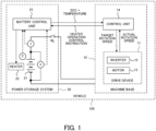
- Fig. 1 illustrates an example of a control system mounted on a vehicle according to an embodiment of the present invention.
- a vehicle 100 according to the embodiment of the present invention is not particularly limited, but is, for example, an electric vehicle that travels by a motor.
- the vehicle 100 is not limited to an electric vehicle, and may be a hybrid vehicle or the like.
- the vehicle 100 is not particularly limited, but is, for example, an industrial vehicle such as a forklift.
- the vehicle 100 is not limited to an industrial vehicle, and may be a passenger car or the like.
- the vehicle 100 includes a machine base 10 and a power storage system 20.
- Fig. 1 mainly depicts a control system according to an embodiment of the present invention, and the vehicle 100 may implement other devices and functions.
- the machine base 10 includes a drive device 11 and a control unit 14.
- the drive device 11 includes an inverter 12 and a motor 13.
- the inverter 12 rotates the motor 13 using the power supplied from the power storage system 20.
- the inverter 12 rotates the motor 13 in accordance with a drive control signal provided from the control unit 14.
- the drive control signal includes a control signal indicating a target rotation speed.
- the inverter 12 controls the rotation speed of the motor 13 according to the target rotation speed.
- the motor 13 is, for example, a motor for traveling of the vehicle 100.
- the motor 13 may be a cargo handling motor of the forklift.
- the drive device 11 may detect an actual rotation speed of the motor 13. In this case, an actual rotation speed representing the actual rotation speed of the motor 13 is notified to the control unit 14.
- the control unit 14 is realized by, for example, a microcomputer including a processor and a memory, and controls the drive device 11 according to an instruction from a user of the vehicle 100.
- the instruction from the user corresponds to, for example, a depression angle (alternatively, the accelerator opening degree) of an accelerator of the vehicle 100.
- the control unit 14 calculates the target rotation speed of the motor 13 according to an instruction from the user.
- the control unit 14 may calculate the target rotation speed based on an instruction from the user and the actual rotation speed notified from the drive device 11.
- control unit 14 may limit power supply to the drive device 11 based on the temperature and the charge state of the battery 21 notified from the power storage system 20.
- the control unit 14 can control an operating state of a heater 22 included in the power storage system 20.
- the power storage system 20 includes the battery 21, the heater 22, a voltage sensor V, a current sensor I, a temperature sensor T, a relay RL, and a battery control unit 23. Note that the power storage system 20 may include other circuits or devices not shown in Fig. 1 .
- the battery 21 is not particularly limited, but is a lithium-ion battery in this embodiment.
- the battery 21 is not particularly limited, but includes a plurality of battery packs connected in series/parallel. In this case, each battery pack may include a plurality of battery cells connected in series.
- the heater 22 is provided in the vicinity of the battery 21 and generates heat in accordance with an instruction from the battery control unit 23. That is, the heater 22 can heat the battery 21 in accordance with an instruction from the battery control unit 23.
- the heater 22 is realized by, for example, a resistance wire. In this case, the heater 22 generates heat by passing a current through the resistance wire.
- the battery control unit 23 controls an on state/off state of the heater 22 by controlling the current flowing through the resistance wire.
- the voltage sensor V detects a voltage of the battery 21.
- the voltage sensor V may detect a voltage between a positive electrode terminal and a negative electrode terminal of the battery 21, may detect a voltage of each battery pack, or may detect a voltage of each battery cell.
- the current sensor I detects a current flowing through the battery 21.
- the current sensor I can detect a charging current when the battery 21 is charged, a current supplied from the battery 21 to a load, and a current regenerated from the load to the battery 21.
- the temperature sensor T is provided in the vicinity of the battery 21 and detects the temperature of the battery 21.
- the relay RL conducts/cuts off a power line connected to the battery 21 according to an instruction from the battery control unit 23. For example, in a case where the battery 21 is a lithium-ion battery, when the battery voltage falls below a predetermined threshold, the relay RL may cut off the power line to protect the battery 21.
- the battery control unit 23 is realized by, for example, a microcomputer including a processor and a memory, and controls a charging operation of the battery 21.
- the battery control unit 23 may control the charging current and the charging voltage of the battery 21 while exchanging a control signal with a charger (not illustrated).
- the battery control unit 23 detects a charge state of the battery 21.
- As the charge state for example, a State of Charge (SOC) of the battery 21 is calculated.
- SOC State of Charge
- the SOC is an index representing a charge rate, and 100% and 0% represent a fully charged state and a fully discharged state, respectively.
- the SOC can be calculated or estimated by a known technique.
- the battery control unit 23 can calculate the SOC based on the integrated value of the current detected by the current sensor I.
- an error may be accumulated. Therefore, when the SOC is calculated based on the integrated value of the current, it is preferable to reset the SOC according to a predetermined trigger.
- the SOC may be reset to "100%" when the battery 21 can be regarded as a fully charged state, or the SOC may be reset to "0%" when the battery 21 can be regarded as a fully discharged state.
- the battery control unit 23 may estimate the SOC by another method. For example, the battery control unit 23 may estimate the SOC based on the voltage of the battery 21.
- the battery control unit 23 notifies the control unit 14 of the SOC of the battery 21. In this case, the battery control unit 23 also notifies the control unit 14 of the temperature of the battery 21 detected by the temperature sensor T. For example, the battery control unit 23 preferably notifies the control unit 14 of the SOC and the temperature of the battery 21 at predetermined time intervals. Alternatively, the battery control unit 23 may notify the control unit 14 of the SOC and the temperature of the battery 21 in response to a request from the control unit 14.
- the battery control unit 23 can adjust the temperature of the battery 21 by controlling the heater 22.
- the battery preferably operates in a predetermined temperature range.
- the internal resistance (alternatively, battery resistance) of the battery 21 increases at a low temperature.
- the voltage of the battery 21 may decrease when power is supplied from the battery 21 to the load.
- charging efficiency of the battery 21 may decrease.
- the battery control unit 23 notifies the control unit 14 of the temperature of the battery 21 measured using the temperature sensor T. Then, the control unit 14 determines whether to cause the heater 22 to generate heat based on the temperature of the battery 21. Specifically, when the temperature of the battery 21 becomes lower than a predetermined temperature threshold, the control unit 14 determines that the heater 22 needs to generate heat. In this case, the battery control unit 23 raises the temperature of the battery 21 by causing the heater 22 to generate heat in accordance with an instruction from the control unit 14. However, as will be described in detail later, the control unit 14 may stop or suppress temperature adjustment performance of the heater 22 even when the temperature of the battery 21 is lower than a predetermined temperature threshold.
- Fig. 2 is a flowchart illustrating an example of processing of the battery control unit 23. Note that this flowchart represents a procedure related to temperature adjustment of the battery 21, and other procedures are omitted. Furthermore, the processing of this flowchart is repeatedly executed at predetermined time intervals, for example.
- the battery control unit 23 detects the temperature of the battery 21 using the output signal of the temperature sensor T.
- the temperature of the battery 21 may be referred to as a "battery temperature”.
- the battery control unit 23 calculates the SOC of the battery 21.
- the battery control unit 23 notifies the control unit 14 of the battery temperature detected in S1 and the SOC calculated in S2.
- the battery control unit 23 receives the heater operation control instruction from the control unit 14.
- the heater operation control instruction represents a heat generation instruction or a stop instruction in this embodiment.
- the heater operation control instruction will be described later.
- the battery control unit 23 causes the heater 22 to generate heat in S6.
- the temperature of the battery 21 increases.
- the battery control unit 23 stops the heat generation of the heater 22 in S7.
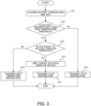
- Fig. 3 is a flowchart illustrating an example of processing of the control unit 14. Note that this flowchart represents a procedure related to temperature adjustment of the battery 21, and other procedures are omitted. Furthermore, the processing of this flowchart is repeatedly executed at predetermined time intervals, for example.
- the control unit 14 acquires information indicating the temperature of the battery 21 and information indicating the SOC from the battery control unit 23.
- the control unit 14 compares the battery temperature with a predetermined temperature threshold.
- the temperature threshold may be determined, for example, in consideration of the amount of increase in the internal resistance of the battery 21 based on the normal temperature. In this embodiment, the temperature threshold is not particularly limited, but is, for example, "5°C".
- the control unit 14 When the battery temperature is equal to or higher than the temperature threshold, the control unit 14 generates a stop instruction indicating that the heater 22 is stopped as the heater operation control instruction in S13, and transmits the stop instruction to the battery control unit 23.
- the control unit 14 compares the SOC of the battery 21 with a predetermined SOC threshold (predetermined charge level) in S14.
- the SOC threshold may be determined, for example, in consideration of a distance that the vehicle 100 can travel using the power of the battery 21.
- the SOC threshold may be a charge amount with which the industrial vehicle can travel from an arbitrary position in the factory to a charging station.
- the SOC threshold is not particularly limited, but is, for example, "15%”.
- the control unit 14 When the SOC of the battery 21 is higher than the SOC threshold, the control unit 14 generates a heat generation instruction representing causing the heater 22 to generate heat as a heater operation control instruction in S15, and transmits the heat generation instruction to the battery control unit 23.
- the control unit 14 limits the power consumption of the drive device 11 in S16.
- the control unit 14 limits the power consumption of the drive device 11 by limiting the target rotation speed of the motor 13.
- the control unit 14 sets the maximum value of the target rotation speed of the motor 13 to be smaller than that at the normal time.
- the control unit 14 more strongly limit the power consumption of the drive device 11 as the difference between the battery temperature and the temperature threshold is larger. In this case, the power consumption of the drive device 11 is limited in stages.
- the control unit 14 generates the above-described stop instruction as a heater operation control instruction and transmits the stop instruction to the battery control unit 23.
- the battery control unit 23 controls the operating state of the heater 22 according to the heater operation control instruction. Therefore, when the heat generation instruction is generated in S15, the battery control unit 23 causes the heater 22 to generate heat. Meanwhile, when the stop instruction is generated in S13 or S17, the battery control unit 23 stops the heater 22.
- the control unit 14 stops the heater 22 and limits the power consumption of the drive device 11.
- the heater control and the motor control are performed based on the comparison between the SOC of the battery 21 and one SOC threshold, but the present invention is not limited to this method. That is, the heater control and the motor control may be performed using two different thresholds.
- Fig. 4 is a flowchart illustrating a variation of processing of the control unit 14. Note that S11 to S13 and S15 to S17 are substantially the same in Figs. 3 and 4 . That is, when the battery temperature is equal to or higher than the temperature threshold, the stop instruction is transmitted to the battery control unit 23 in S13. Meanwhile, when the battery temperature is lower than the temperature threshold, the processing of the control unit 14 proceeds to S21.
- the control unit 14 compares the SOC of the battery 21 with the first SOC threshold (first charge level).
- the first SOC threshold is not particularly limited, but may be the same as the SOC threshold used in the procedure illustrated in Fig. 3 .
- the control unit 14 transmits a heat generation instruction to the battery control unit 23 in S15.
- the control unit 14 limits the power consumption of the drive device 11 in S16. For example, the control unit 14 sets the maximum value of the target rotation speed of the motor 13 to be smaller than that at the normal time.
- the control unit 14 compares the SOC of the battery 21 with the second SOC threshold (second charge level).
- the second SOC threshold is assumed to be lower than the first SOC threshold in this embodiment.
- the control unit 14 transmits a heat generation instruction to the battery control unit 23 in S15.
- the control unit 14 transmits a stop instruction to the battery control unit 23 in S17.
- the control unit 14 limits the target rotation speed of the motor 13, but the heater 22 generates heat.
- the control unit 14 limits the target rotation speed of the motor 13 and stops the heater 22. That is, while the SOC of the battery 21 decreases, the power consumption of the motor 13 is first limited, and then the heat generation of the heater 22 is limited. According to this procedure, the period during which the battery 21 is used in the low temperature state is shortened as compared with the procedure illustrated in Fig. 3 .
- the variation of the embodiment of the present invention is not limited to this procedure, and the heat generation of the heater 22 may be limited first, and then the power consumption of the motor 13 may be limited.
- the two SOC thresholds are preferably determined in consideration of a trade-off relationship between battery deterioration and an operating time of the vehicle 100.
- the procedure illustrated in Fig. 4 is the same as the procedure illustrated in Fig. 3 .
- the battery 21 is not limited to a lithium-ion battery, and may be a battery using other materials.
- the present invention is effective for a battery that needs to be protected when a battery voltage drops.
- the SOC threshold may be arbitrarily set by the user of the vehicle 100 using an interface mounted on the machine base 10.
- the SOC is used as the charge state of the battery 21, but the present invention is not limited to this method.
- the control unit 14 may control the operations of the heater 22 and the motor 13 based on the voltage of the battery 21, the voltage of the battery pack, or the voltage of the battery cell, instead of the SOC.
- the heater 22 is controlled to the ON state or the OFF state, but the present invention is not limited to this method.
- the control unit 14 may control the temperature adjustment performance of the heater 22 according to the temperature of the battery 21.
- the control unit 14 gives a suppression instruction indicating suppression of the amount of heat generated by the heater 22 to the battery control unit 23. Then, the battery control unit 23 adjusts the current flowing to the heater 22 based on the suppression instruction.
- the power consumption of the drive device 11 is limited by limiting the target rotation speed of the motor 13, but the present invention is not limited to this method.
- the control unit 14 may limit the accelerator opening degree of the vehicle 100, or may change the correspondence relationship between the accelerator opening degree and the target rotation speed of the motor 13.
- the control unit 14 determines the operating state of the heater 22, and the battery control unit 23 controls the heater 22 according to the instruction given from the control unit 14, but the present invention is not limited to this method.
- the battery control unit 23 may control the operating state of the heater 22 based on the battery temperature, and when the SOC of the battery 21 is lower than the SOC threshold, the control unit 14 may give the stop instruction to the battery control unit 23. In this case, even when the battery temperature is equal to or lower than the temperature threshold, the battery control unit 23 stops the heater 22 when a stop instruction is given.
Landscapes
- Engineering & Computer Science (AREA)
- Power Engineering (AREA)
- Manufacturing & Machinery (AREA)
- Chemical & Material Sciences (AREA)
- Chemical Kinetics & Catalysis (AREA)
- Electrochemistry (AREA)
- General Chemical & Material Sciences (AREA)
- Mechanical Engineering (AREA)
- Transportation (AREA)
- Life Sciences & Earth Sciences (AREA)
- Sustainable Development (AREA)
- Sustainable Energy (AREA)
- Automation & Control Theory (AREA)
- Secondary Cells (AREA)
- Physics & Mathematics (AREA)
- Electromagnetism (AREA)
- Electric Propulsion And Braking For Vehicles (AREA)
- Charge And Discharge Circuits For Batteries Or The Like (AREA)
Abstract
Description
- The present invention relates to a system and a method for controlling a battery mounted on a vehicle.
- In recent years, an electric vehicle that drives a-motor with power supplied from a battery has been widely used. For example, electrification of industrial vehicles such as forklift trucks has been advanced.
- A battery generally preferably operates in a predetermined temperature range. For this reason, a power-storage system having a temperature control function is known. Meanwhile, in the electric vehicle, it is required to increase a cruisable distance. For this reason, a method of limiting the opportunity to adjust the temperature of the battery based on a battery deterioration index (charge rate, temperature, or the like) has been proposed (for example, Patent Literature 1). As an example, even in a case where the temperature of the battery is out of the predetermined temperature region, the temperature adjustment is not executed when the charge rate enters a dangerous region. Then, since the power consumption is suppressed, the cruising distance of the electric vehicle becomes long.
- Patent Literature 1:
JP 2020-119694 A - As described above, a method of increasing the cruisable distance by limiting the opportunity to adjust the temperature of the battery based on the battery deterioration index in the electric vehicle has been proposed. However, this method may increase an internal resistance of the battery because the opportunity to adjust the temperature of the battery is limited. When the internal resistance of the battery increases, the battery voltage may decrease when power is supplied from the battery to the load.
- An object according to one aspect of the present invention is to avoid a decrease in battery voltage while suppressing a decrease in temperature of a battery mounted on a vehicle.
- According to one aspect of the present invention, there is provided a control system including: a temperature sensor that detects a temperature of a battery mounted on a vehicle; a heater that heats the battery; a battery control unit that detects a charge state of the battery and controls an operating state of the heater; and a control unit that controls a drive device that operates with power supplied from the battery and gives an instruction related to the operating state of the heater to the battery control unit. When the temperature of the battery is lower than a predetermined temperature threshold and the charge state of the battery is higher than a predetermined charge level, the control unit gives a heat generation instruction indicating that the heater generates heat to the battery control unit. When the temperature of the battery is lower than the temperature threshold and the charge state of the battery is equal to or lower than the charge level, the control unit gives a stop instruction indicating that the heater is stopped or a suppression instruction indicating that an amount of heat generated by the heater is suppressed to the battery control unit, and limits power consumption of the drive device.
- As described above, in the control system according to the embodiment of the present invention, when the temperature of the battery is lower than the temperature threshold, the temperature of the battery is increased by causing the heater to generate heat. However, even when the temperature of the battery is lower than the temperature threshold, the heater is stopped and the power consumption of the drive device is limited when the charge state of the battery is equal to or lower than the predetermined charge level (for example, a predetermined SOC threshold). As a result, since the current supplied from the battery to the drive device is suppressed, even when the internal resistance of the battery increases, voltage drop does not increase, and a lowering range of the battery voltage can be suppressed.
- In the above configuration, when the temperature of the battery is lower than the temperature threshold and the charge state of the battery is equal to or lower than the charge level, the control unit may more strongly limit power consumption of the drive device as a difference between the temperature of the battery and the temperature threshold is larger. In addition, in a case where the drive device includes a motor mounted on the vehicle, the control unit may limit power consumption of the drive device by limiting a rotation speed of the motor.
- According to the present invention, it is possible to avoid a decrease in a battery voltage while suppressing a decrease in temperature of a battery mounted on a vehicle.
-
-
Fig. 1 is a diagram illustrating an example of a control system mounted on a vehicle according to an embodiment of the present invention. -
Fig. 2 is a flowchart illustrating an example of processing of a battery control unit. -
Fig. 3 is a flowchart illustrating an example of processing of a control unit. -
Fig. 4 is a flowchart illustrating a variation of the processing of the control unit. -
Fig. 1 illustrates an example of a control system mounted on a vehicle according to an embodiment of the present invention. Avehicle 100 according to the embodiment of the present invention is not particularly limited, but is, for example, an electric vehicle that travels by a motor. However, thevehicle 100 is not limited to an electric vehicle, and may be a hybrid vehicle or the like. Thevehicle 100 is not particularly limited, but is, for example, an industrial vehicle such as a forklift. However, thevehicle 100 is not limited to an industrial vehicle, and may be a passenger car or the like. - The
vehicle 100 includes amachine base 10 and apower storage system 20. Note thatFig. 1 mainly depicts a control system according to an embodiment of the present invention, and thevehicle 100 may implement other devices and functions. - The
machine base 10 includes adrive device 11 and acontrol unit 14. Thedrive device 11 includes aninverter 12 and amotor 13. Theinverter 12 rotates themotor 13 using the power supplied from thepower storage system 20. In this case, theinverter 12 rotates themotor 13 in accordance with a drive control signal provided from thecontrol unit 14. In this example, the drive control signal includes a control signal indicating a target rotation speed. In this case, theinverter 12 controls the rotation speed of themotor 13 according to the target rotation speed. Themotor 13 is, for example, a motor for traveling of thevehicle 100. Alternatively, when thevehicle 100 is a forklift, themotor 13 may be a cargo handling motor of the forklift. Thedrive device 11 may detect an actual rotation speed of themotor 13. In this case, an actual rotation speed representing the actual rotation speed of themotor 13 is notified to thecontrol unit 14. - The
control unit 14 is realized by, for example, a microcomputer including a processor and a memory, and controls thedrive device 11 according to an instruction from a user of thevehicle 100. The instruction from the user corresponds to, for example, a depression angle (alternatively, the accelerator opening degree) of an accelerator of thevehicle 100. In this case, thecontrol unit 14 calculates the target rotation speed of themotor 13 according to an instruction from the user. Alternatively, thecontrol unit 14 may calculate the target rotation speed based on an instruction from the user and the actual rotation speed notified from thedrive device 11. - As will be described in detail later, the
control unit 14 may limit power supply to thedrive device 11 based on the temperature and the charge state of thebattery 21 notified from thepower storage system 20. Thecontrol unit 14 can control an operating state of aheater 22 included in thepower storage system 20. - The
power storage system 20 includes thebattery 21, theheater 22, a voltage sensor V, a current sensor I, a temperature sensor T, a relay RL, and abattery control unit 23. Note that thepower storage system 20 may include other circuits or devices not shown inFig. 1 . - The
battery 21 is not particularly limited, but is a lithium-ion battery in this embodiment. Thebattery 21 is not particularly limited, but includes a plurality of battery packs connected in series/parallel. In this case, each battery pack may include a plurality of battery cells connected in series. - The
heater 22 is provided in the vicinity of thebattery 21 and generates heat in accordance with an instruction from thebattery control unit 23. That is, theheater 22 can heat thebattery 21 in accordance with an instruction from thebattery control unit 23. Theheater 22 is realized by, for example, a resistance wire. In this case, theheater 22 generates heat by passing a current through the resistance wire. In addition, thebattery control unit 23 controls an on state/off state of theheater 22 by controlling the current flowing through the resistance wire. - The voltage sensor V detects a voltage of the
battery 21. The voltage sensor V may detect a voltage between a positive electrode terminal and a negative electrode terminal of thebattery 21, may detect a voltage of each battery pack, or may detect a voltage of each battery cell. The current sensor I detects a current flowing through thebattery 21. The current sensor I can detect a charging current when thebattery 21 is charged, a current supplied from thebattery 21 to a load, and a current regenerated from the load to thebattery 21. The temperature sensor T is provided in the vicinity of thebattery 21 and detects the temperature of thebattery 21. The relay RL conducts/cuts off a power line connected to thebattery 21 according to an instruction from thebattery control unit 23. For example, in a case where thebattery 21 is a lithium-ion battery, when the battery voltage falls below a predetermined threshold, the relay RL may cut off the power line to protect thebattery 21. - The
battery control unit 23 is realized by, for example, a microcomputer including a processor and a memory, and controls a charging operation of thebattery 21. In this case, thebattery control unit 23 may control the charging current and the charging voltage of thebattery 21 while exchanging a control signal with a charger (not illustrated). In addition, thebattery control unit 23 detects a charge state of thebattery 21. As the charge state, for example, a State of Charge (SOC) of thebattery 21 is calculated. The SOC is an index representing a charge rate, and 100% and 0% represent a fully charged state and a fully discharged state, respectively. - The SOC can be calculated or estimated by a known technique. For example, the
battery control unit 23 can calculate the SOC based on the integrated value of the current detected by the current sensor I. However, when the SOC is calculated by this method, an error may be accumulated. Therefore, when the SOC is calculated based on the integrated value of the current, it is preferable to reset the SOC according to a predetermined trigger. For example, the SOC may be reset to "100%" when thebattery 21 can be regarded as a fully charged state, or the SOC may be reset to "0%" when thebattery 21 can be regarded as a fully discharged state. In addition, thebattery control unit 23 may estimate the SOC by another method. For example, thebattery control unit 23 may estimate the SOC based on the voltage of thebattery 21. - The
battery control unit 23 notifies thecontrol unit 14 of the SOC of thebattery 21. In this case, thebattery control unit 23 also notifies thecontrol unit 14 of the temperature of thebattery 21 detected by the temperature sensor T. For example, thebattery control unit 23 preferably notifies thecontrol unit 14 of the SOC and the temperature of thebattery 21 at predetermined time intervals. Alternatively, thebattery control unit 23 may notify thecontrol unit 14 of the SOC and the temperature of thebattery 21 in response to a request from thecontrol unit 14. - Furthermore, the
battery control unit 23 can adjust the temperature of thebattery 21 by controlling theheater 22. Here, in general, the battery preferably operates in a predetermined temperature range. For example, in a case where thebattery 21 is a lithium-ion battery, the internal resistance (alternatively, battery resistance) of thebattery 21 increases at a low temperature. Here, when the internal resistance increases, the voltage of thebattery 21 may decrease when power is supplied from thebattery 21 to the load. Alternatively, charging efficiency of thebattery 21 may decrease. - Therefore, the
battery control unit 23 notifies thecontrol unit 14 of the temperature of thebattery 21 measured using the temperature sensor T. Then, thecontrol unit 14 determines whether to cause theheater 22 to generate heat based on the temperature of thebattery 21. Specifically, when the temperature of thebattery 21 becomes lower than a predetermined temperature threshold, thecontrol unit 14 determines that theheater 22 needs to generate heat. In this case, thebattery control unit 23 raises the temperature of thebattery 21 by causing theheater 22 to generate heat in accordance with an instruction from thecontrol unit 14. However, as will be described in detail later, thecontrol unit 14 may stop or suppress temperature adjustment performance of theheater 22 even when the temperature of thebattery 21 is lower than a predetermined temperature threshold. -
Fig. 2 is a flowchart illustrating an example of processing of thebattery control unit 23. Note that this flowchart represents a procedure related to temperature adjustment of thebattery 21, and other procedures are omitted. Furthermore, the processing of this flowchart is repeatedly executed at predetermined time intervals, for example. - In S1, the
battery control unit 23 detects the temperature of thebattery 21 using the output signal of the temperature sensor T. In the following description, the temperature of thebattery 21 may be referred to as a "battery temperature". In S2, thebattery control unit 23 calculates the SOC of thebattery 21. In S3, thebattery control unit 23 notifies thecontrol unit 14 of the battery temperature detected in S1 and the SOC calculated in S2. - In S4 to S5, the
battery control unit 23 receives the heater operation control instruction from thecontrol unit 14. The heater operation control instruction represents a heat generation instruction or a stop instruction in this embodiment. The heater operation control instruction will be described later. When the heat generation instruction is received, thebattery control unit 23 causes theheater 22 to generate heat in S6. As a result, the temperature of thebattery 21 increases. Meanwhile, when the stop instruction is received, thebattery control unit 23 stops the heat generation of theheater 22 in S7. -
Fig. 3 is a flowchart illustrating an example of processing of thecontrol unit 14. Note that this flowchart represents a procedure related to temperature adjustment of thebattery 21, and other procedures are omitted. Furthermore, the processing of this flowchart is repeatedly executed at predetermined time intervals, for example. - In S11, the
control unit 14 acquires information indicating the temperature of thebattery 21 and information indicating the SOC from thebattery control unit 23. In S12, thecontrol unit 14 compares the battery temperature with a predetermined temperature threshold. The temperature threshold may be determined, for example, in consideration of the amount of increase in the internal resistance of thebattery 21 based on the normal temperature. In this embodiment, the temperature threshold is not particularly limited, but is, for example, "5°C". When the battery temperature is equal to or higher than the temperature threshold, thecontrol unit 14 generates a stop instruction indicating that theheater 22 is stopped as the heater operation control instruction in S13, and transmits the stop instruction to thebattery control unit 23. - When the battery temperature is lower than the temperature threshold, the
control unit 14 compares the SOC of thebattery 21 with a predetermined SOC threshold (predetermined charge level) in S14. The SOC threshold may be determined, for example, in consideration of a distance that thevehicle 100 can travel using the power of thebattery 21. For example, when thevehicle 100 is an industrial vehicle used in a factory, the SOC threshold may be a charge amount with which the industrial vehicle can travel from an arbitrary position in the factory to a charging station. The SOC threshold is not particularly limited, but is, for example, "15%". When the SOC of thebattery 21 is higher than the SOC threshold, thecontrol unit 14 generates a heat generation instruction representing causing theheater 22 to generate heat as a heater operation control instruction in S15, and transmits the heat generation instruction to thebattery control unit 23. - When the battery temperature is lower than the temperature threshold and the SOC of the
battery 21 is equal to or lower than the SOC threshold, thecontrol unit 14 limits the power consumption of thedrive device 11 in S16. In this embodiment, thecontrol unit 14 limits the power consumption of thedrive device 11 by limiting the target rotation speed of themotor 13. For example, thecontrol unit 14 sets the maximum value of the target rotation speed of themotor 13 to be smaller than that at the normal time. In addition, it is preferable that thecontrol unit 14 more strongly limit the power consumption of thedrive device 11 as the difference between the battery temperature and the temperature threshold is larger. In this case, the power consumption of thedrive device 11 is limited in stages. For example, when the difference between the battery temperature and the temperature threshold is 2°C or less, the maximum value of the target rotation speed of themotor 13 is limited to 80% of the normal time, and when the difference exceeds 2°C, the maximum value of the target rotation speed of themotor 13 is limited to 50% of the normal time. Alternatively, the limit width of the maximum value of the target rotation speed of themotor 13 may be proportional to the difference between the battery temperature and the temperature threshold. Thereafter, in S17, thecontrol unit 14 generates the above-described stop instruction as a heater operation control instruction and transmits the stop instruction to thebattery control unit 23. - As described with reference to
Fig. 2 , thebattery control unit 23 controls the operating state of theheater 22 according to the heater operation control instruction. Therefore, when the heat generation instruction is generated in S15, thebattery control unit 23 causes theheater 22 to generate heat. Meanwhile, when the stop instruction is generated in S13 or S17, thebattery control unit 23 stops theheater 22. - As described above, in the control system according to the embodiment of the present invention, when the battery temperature is lower than the temperature threshold, the battery temperature is increased by causing the
heater 22 to generate heat. As a result, an increase in the internal resistance of thebattery 21 is suppressed, and a decrease in the battery voltage can be avoided. However, even when the battery temperature is lower than the temperature threshold, theheater 22 is stopped when the SOC of thebattery 21 is lower than the SOC threshold. As a result, battery consumption is suppressed, and a driving time of the battery is lengthened. However, when theheater 22 is stopped, the temperature of thebattery 21 remains low, and the battery voltage may decrease due to an increase in the internal resistance of thebattery 21. Therefore, thecontrol unit 14 stops theheater 22 and limits the power consumption of thedrive device 11. As a result, since the current supplied from thebattery 21 to the load (that is, the drive device 11) of themachine base 10 is suppressed, even when the internal resistance of thebattery 21 increases, the voltage drop does not increase, and the lowering range of the battery voltage can be suppressed. In other words, an operation area (the temperature and/or the SOC of the battery 21) where the battery voltage does not decrease is wider than the case where the power consumption of thedrive device 11 is not limited. - In the procedure illustrated in
Fig. 3 , the heater control and the motor control are performed based on the comparison between the SOC of thebattery 21 and one SOC threshold, but the present invention is not limited to this method. That is, the heater control and the motor control may be performed using two different thresholds. -
Fig. 4 is a flowchart illustrating a variation of processing of thecontrol unit 14. Note that S11 to S13 and S15 to S17 are substantially the same inFigs. 3 and4 . That is, when the battery temperature is equal to or higher than the temperature threshold, the stop instruction is transmitted to thebattery control unit 23 in S13. Meanwhile, when the battery temperature is lower than the temperature threshold, the processing of thecontrol unit 14 proceeds to S21. - In S21, the
control unit 14 compares the SOC of thebattery 21 with the first SOC threshold (first charge level). The first SOC threshold is not particularly limited, but may be the same as the SOC threshold used in the procedure illustrated inFig. 3 . When the SOC of thebattery 21 is higher than the first SOC threshold, thecontrol unit 14 transmits a heat generation instruction to thebattery control unit 23 in S15. Meanwhile, when the SOC of thebattery 21 is equal to or lower than the first SOC threshold, thecontrol unit 14 limits the power consumption of thedrive device 11 in S16. For example, thecontrol unit 14 sets the maximum value of the target rotation speed of themotor 13 to be smaller than that at the normal time. - In S22, the
control unit 14 compares the SOC of thebattery 21 with the second SOC threshold (second charge level). The second SOC threshold is assumed to be lower than the first SOC threshold in this embodiment. When the SOC of thebattery 21 is higher than the second SOC threshold, thecontrol unit 14 transmits a heat generation instruction to thebattery control unit 23 in S15. Meanwhile, when the SOC of thebattery 21 is equal to or lower than the second SOC threshold, thecontrol unit 14 transmits a stop instruction to thebattery control unit 23 in S17. - As described above, in the procedure illustrated in
Fig. 4 , when the battery temperature is lower than the temperature threshold and the SOC of thebattery 21 is lower than the first SOC threshold and higher than the second threshold, thecontrol unit 14 limits the target rotation speed of themotor 13, but theheater 22 generates heat. When the SOC of thebattery 21 falls below the second threshold, thecontrol unit 14 limits the target rotation speed of themotor 13 and stops theheater 22. That is, while the SOC of thebattery 21 decreases, the power consumption of themotor 13 is first limited, and then the heat generation of theheater 22 is limited. According to this procedure, the period during which thebattery 21 is used in the low temperature state is shortened as compared with the procedure illustrated inFig. 3 . However, the variation of the embodiment of the present invention is not limited to this procedure, and the heat generation of theheater 22 may be limited first, and then the power consumption of themotor 13 may be limited. - The two SOC thresholds are preferably determined in consideration of a trade-off relationship between battery deterioration and an operating time of the
vehicle 100. When the two SOC thresholds are the same, the procedure illustrated inFig. 4 is the same as the procedure illustrated inFig. 3 . - The
battery 21 is not limited to a lithium-ion battery, and may be a battery using other materials. For example, the present invention is effective for a battery that needs to be protected when a battery voltage drops. Further, the SOC threshold may be arbitrarily set by the user of thevehicle 100 using an interface mounted on themachine base 10. - In the above-described embodiment, the SOC is used as the charge state of the
battery 21, but the present invention is not limited to this method. For example, thecontrol unit 14 may control the operations of theheater 22 and themotor 13 based on the voltage of thebattery 21, the voltage of the battery pack, or the voltage of the battery cell, instead of the SOC. - In the above-described embodiment, the
heater 22 is controlled to the ON state or the OFF state, but the present invention is not limited to this method. For example, thecontrol unit 14 may control the temperature adjustment performance of theheater 22 according to the temperature of thebattery 21. In this case, thecontrol unit 14 gives a suppression instruction indicating suppression of the amount of heat generated by theheater 22 to thebattery control unit 23. Then, thebattery control unit 23 adjusts the current flowing to theheater 22 based on the suppression instruction. - In the above-described embodiment, the power consumption of the
drive device 11 is limited by limiting the target rotation speed of themotor 13, but the present invention is not limited to this method. For example, when the battery temperature is lower than the temperature threshold and the SOC of thebattery 21 is equal to or lower than the SOC threshold, thecontrol unit 14 may limit the accelerator opening degree of thevehicle 100, or may change the correspondence relationship between the accelerator opening degree and the target rotation speed of themotor 13. - In the above-described embodiment, the
control unit 14 determines the operating state of theheater 22, and thebattery control unit 23 controls theheater 22 according to the instruction given from thecontrol unit 14, but the present invention is not limited to this method. For example, thebattery control unit 23 may control the operating state of theheater 22 based on the battery temperature, and when the SOC of thebattery 21 is lower than the SOC threshold, thecontrol unit 14 may give the stop instruction to thebattery control unit 23. In this case, even when the battery temperature is equal to or lower than the temperature threshold, thebattery control unit 23 stops theheater 22 when a stop instruction is given. -
- 10
- machine base
- 11
- drive device
- 12
- inverter
- 13
- motor
- 14
- control unit
- 20
- power storage system
- 21
- battery
- 22
- heater
- 23
- battery control unit
- 100
- vehicle
Claims (5)
- A control system comprising:a temperature sensor that detects a temperature of a battery mounted on a vehicle;a heater that heats the battery;a battery control unit that detects a charge state of the battery and controls an operating state of the heater; anda control unit that controls a drive device that operates with power supplied from the battery and gives an instruction related to the operating state of the heater to the battery control unit, whereinwhen the temperature of the battery is lower than a predetermined temperature threshold and the charge state of the battery is higher than a predetermined charge level, the control unit gives a heat generation instruction indicating that the heater generates heat to the battery control unit, andwhen the temperature of the battery is lower than the temperature threshold and the charge state of the battery is equal to or lower than the charge level, the control unit gives a stop instruction indicating that the heater is stopped or a suppression instruction indicating that an amount of heat generated by the heater is suppressed to the battery control unit, and limits power consumption of the drive device.
- The control system according to claim 1, wherein
when the temperature of the battery is lower than the temperature threshold and the charge state of the battery is equal to or lower than the charge level, the control unit more strongly limits power consumption of the drive device as a difference between the temperature of the battery and the temperature threshold is larger. - The control system according to claim 1, whereinthe drive device includes a motor mounted on the vehicle, andthe control unit limits power consumption of the drive device by limiting a rotation speed of the motor.
- A control system comprising:a temperature sensor that detects a temperature of a battery mounted on a vehicle;a heater that heats the battery;a battery control unit that detects a charge state of the battery and controls an operating state of the heater; anda control unit that controls a drive device that operates with power supplied from the battery and gives an instruction related to the operating state of the heater to the battery control unit, whereinwhen the temperature of the battery is lower than a predetermined temperature threshold and the charge state of the battery is higher than a first charge level, the control unit gives a heat generation instruction indicating that the heater generates heat to the battery control unit,when the temperature of the battery is lower than the temperature threshold and the charge state of the battery is equal to or lower than the first charge level, the control unit limits power consumption of the drive device, andwhen the temperature of the battery is lower than the temperature threshold and the charge state of the battery is lower than or equal to a second charge level lower than the first charge level, the control unit gives a stop instruction indicating that the heater is stopped or a suppression instruction indicating that an amount of heat generated by the heater is suppressed to the battery control unit.
- A vehicle comprising:a battery;a drive device that operates with power supplied from the battery; anda temperature sensor that detects a temperature of the battery;a heater that heats the battery;a battery control unit that detects a charge state of the battery and controls an operating state of the heater; anda control unit that controls the drive device and gives an instruction related to the operating state of the heater to the battery control unit, whereinwhen the temperature of the battery is lower than a predetermined temperature threshold and the charge state of the battery is higher than a predetermined charge level, the control unit gives a heat generation instruction indicating that the heater generates heat to the battery control unit, andwhen the temperature of the battery is lower than the temperature threshold and the charge state of the battery is equal to or lower than the charge level, the control unit gives a stop instruction indicating that the heater is stopped or a suppression instruction indicating that an amount of heat generated by the heater is suppressed to the battery control unit, and limits power consumption of the drive device.
Applications Claiming Priority (2)
| Application Number | Priority Date | Filing Date | Title |
|---|---|---|---|
| JP2021152292A JP7600939B2 (en) | 2021-09-17 | 2021-09-17 | Control System |
| PCT/JP2022/030542 WO2023042581A1 (en) | 2021-09-17 | 2022-08-10 | Control system |
Publications (3)
| Publication Number | Publication Date |
|---|---|
| EP4403409A1 true EP4403409A1 (en) | 2024-07-24 |
| EP4403409A4 EP4403409A4 (en) | 2025-01-01 |
| EP4403409B1 EP4403409B1 (en) | 2025-12-17 |
Family
ID=85602768
Family Applications (1)
| Application Number | Title | Priority Date | Filing Date |
|---|---|---|---|
| EP22869728.0A Active EP4403409B1 (en) | 2021-09-17 | 2022-08-10 | Control system |
Country Status (8)
| Country | Link |
|---|---|
| US (1) | US20250125436A1 (en) |
| EP (1) | EP4403409B1 (en) |
| JP (1) | JP7600939B2 (en) |
| CN (1) | CN117999191A (en) |
| AU (1) | AU2022348236B2 (en) |
| CA (1) | CA3231437A1 (en) |
| TW (1) | TWI828288B (en) |
| WO (1) | WO2023042581A1 (en) |
Family Cites Families (16)
| Publication number | Priority date | Publication date | Assignee | Title |
|---|---|---|---|---|
| JP3749184B2 (en) | 2002-01-31 | 2006-02-22 | 三洋電機株式会社 | Battery device for vehicle |
| JP4020650B2 (en) | 2002-01-30 | 2007-12-12 | 三洋電機株式会社 | Battery device for vehicle |
| JP2005176484A (en) | 2003-12-10 | 2005-06-30 | Honda Motor Co Ltd | Control device for hybrid vehicle |
| US7154068B2 (en) * | 2004-05-26 | 2006-12-26 | Ford Global Technologies, Llc | Method and system for a vehicle battery temperature control |
| JP5162100B2 (en) * | 2006-03-07 | 2013-03-13 | プライムアースEvエナジー株式会社 | Secondary battery temperature control device, vehicle battery pack, and secondary battery temperature control program |
| JP5866835B2 (en) | 2011-07-13 | 2016-02-24 | マツダ株式会社 | Battery heating device for electric drive vehicle |
| US8620506B2 (en) * | 2011-12-21 | 2013-12-31 | Ford Global Technologies, Llc | Method and system for thermal management of a high voltage battery for a vehicle |
| JP6545435B2 (en) | 2014-03-07 | 2019-07-17 | 三菱重工業株式会社 | Vehicle control device, vehicle, and control method of vehicle |
| JP6331697B2 (en) * | 2014-05-28 | 2018-05-30 | トヨタ自動車株式会社 | Power storage system |
| US10770766B2 (en) * | 2015-09-28 | 2020-09-08 | Honda Motor Co., Ltd. | Heating control device |
| EP3354499B1 (en) * | 2017-01-25 | 2021-11-10 | Robert Bosch GmbH | Device for heating a traction battery and method for operating a traction battery |
| JP7155642B2 (en) | 2018-06-15 | 2022-10-19 | 株式会社デンソー | Drive control device for vehicle drive system |
| EP3584106A1 (en) * | 2018-06-19 | 2019-12-25 | Einride Ab | Predictive remote thermal managment |
| JP7213698B2 (en) * | 2019-01-22 | 2023-01-27 | サンデン株式会社 | VEHICLE BATTERY TEMPERATURE ADJUSTMENT DEVICE AND VEHICLE AIR CONDITIONER WITH SAME |
| JP7207007B2 (en) | 2019-02-26 | 2023-01-18 | トヨタ自動車株式会社 | vehicle controller |
| JP7498625B2 (en) | 2020-01-31 | 2024-06-12 | 株式会社デンソー | Vehicle control device, program, and vehicle control method |
-
2021
- 2021-09-17 JP JP2021152292A patent/JP7600939B2/en active Active
-
2022
- 2022-08-10 EP EP22869728.0A patent/EP4403409B1/en active Active
- 2022-08-10 US US18/691,675 patent/US20250125436A1/en active Pending
- 2022-08-10 AU AU2022348236A patent/AU2022348236B2/en active Active
- 2022-08-10 WO PCT/JP2022/030542 patent/WO2023042581A1/en not_active Ceased
- 2022-08-10 CN CN202280062572.5A patent/CN117999191A/en active Pending
- 2022-08-10 CA CA3231437A patent/CA3231437A1/en active Pending
- 2022-08-30 TW TW111132620A patent/TWI828288B/en active
Also Published As
| Publication number | Publication date |
|---|---|
| AU2022348236A1 (en) | 2024-03-28 |
| CN117999191A (en) | 2024-05-07 |
| AU2022348236B2 (en) | 2025-04-17 |
| US20250125436A1 (en) | 2025-04-17 |
| WO2023042581A1 (en) | 2023-03-23 |
| EP4403409B1 (en) | 2025-12-17 |
| TW202320391A (en) | 2023-05-16 |
| JP2023044323A (en) | 2023-03-30 |
| EP4403409A4 (en) | 2025-01-01 |
| TWI828288B (en) | 2024-01-01 |
| CA3231437A1 (en) | 2023-03-23 |
| JP7600939B2 (en) | 2024-12-17 |
Similar Documents
| Publication | Publication Date | Title |
|---|---|---|
| US9849793B2 (en) | Electrical storage system for vehicle | |
| US8981729B2 (en) | Charging control apparatus and charging control method for battery | |
| JP4494453B2 (en) | Secondary battery control device and control method | |
| CN103339788B (en) | Control device and control method for power storage device | |
| US20110148361A1 (en) | Battery system and method for detecting current restriction state in a battery system | |
| JP5470829B2 (en) | Discrimination device for discriminating the state of a lithium ion battery | |
| JP5762699B2 (en) | Hybrid car power supply | |
| CN106797126A (en) | Secondary battery charging system and charging method | |
| JP2013145175A (en) | Battery system and short circuit detection method | |
| JP5256668B2 (en) | Energy control system for fuel cell vehicle | |
| JP5842607B2 (en) | Non-aqueous secondary battery control device and control method | |
| EP4403409A1 (en) | Control system | |
| JP5696028B2 (en) | Battery control device and power storage device | |
| JP2020162375A (en) | vehicle | |
| KR101539810B1 (en) | Battery pack control method and apparatus | |
| JP2019170022A (en) | vehicle | |
| US20250162526A1 (en) | Charging system and vehicle | |
| JP2001339868A (en) | Control method for charge/discharge of battery | |
| JP5169479B2 (en) | Vehicle control device | |
| KR102716979B1 (en) | Apparatus for Controlling Power of Parallel Multi Battery Pack and Method thereof |
Legal Events
| Date | Code | Title | Description |
|---|---|---|---|
| STAA | Information on the status of an ep patent application or granted ep patent |
Free format text: STATUS: THE INTERNATIONAL PUBLICATION HAS BEEN MADE |
|
| PUAI | Public reference made under article 153(3) epc to a published international application that has entered the european phase |
Free format text: ORIGINAL CODE: 0009012 |
|
| STAA | Information on the status of an ep patent application or granted ep patent |
Free format text: STATUS: REQUEST FOR EXAMINATION WAS MADE |
|
| 17P | Request for examination filed |
Effective date: 20240322 |
|
| AK | Designated contracting states |
Kind code of ref document: A1 Designated state(s): AL AT BE BG CH CY CZ DE DK EE ES FI FR GB GR HR HU IE IS IT LI LT LU LV MC MK MT NL NO PL PT RO RS SE SI SK SM TR |
|
| DAV | Request for validation of the european patent (deleted) | ||
| DAX | Request for extension of the european patent (deleted) | ||
| A4 | Supplementary search report drawn up and despatched |
Effective date: 20241202 |
|
| RIC1 | Information provided on ipc code assigned before grant |
Ipc: B60L 58/25 20190101ALI20241126BHEP Ipc: H01M 10/63 20140101ALI20241126BHEP Ipc: B60L 1/02 20060101ALI20241126BHEP Ipc: B60L 58/16 20190101ALI20241126BHEP Ipc: H01M 10/6571 20140101ALI20241126BHEP Ipc: H01M 10/633 20140101ALI20241126BHEP Ipc: H01M 10/625 20140101ALI20241126BHEP Ipc: H01M 10/615 20140101ALI20241126BHEP Ipc: H01M 10/48 20060101ALI20241126BHEP Ipc: B60L 58/12 20190101ALI20241126BHEP Ipc: B60L 3/00 20190101ALI20241126BHEP Ipc: B60L 58/27 20190101AFI20241126BHEP |
|
| STAA | Information on the status of an ep patent application or granted ep patent |
Free format text: STATUS: EXAMINATION IS IN PROGRESS |
|
| 17Q | First examination report despatched |
Effective date: 20250425 |
|
| GRAP | Despatch of communication of intention to grant a patent |
Free format text: ORIGINAL CODE: EPIDOSNIGR1 |
|
| STAA | Information on the status of an ep patent application or granted ep patent |
Free format text: STATUS: GRANT OF PATENT IS INTENDED |
|
| INTG | Intention to grant announced |
Effective date: 20250829 |
|
| GRAS | Grant fee paid |
Free format text: ORIGINAL CODE: EPIDOSNIGR3 |
|
| GRAA | (expected) grant |
Free format text: ORIGINAL CODE: 0009210 |
|
| STAA | Information on the status of an ep patent application or granted ep patent |
Free format text: STATUS: THE PATENT HAS BEEN GRANTED |
|
| AK | Designated contracting states |
Kind code of ref document: B1 Designated state(s): AL AT BE BG CH CY CZ DE DK EE ES FI FR GB GR HR HU IE IS IT LI LT LU LV MC MK MT NL NO PL PT RO RS SE SI SK SM TR |
|
| REG | Reference to a national code |
Ref country code: CH Ref legal event code: F10 Free format text: ST27 STATUS EVENT CODE: U-0-0-F10-F00 (AS PROVIDED BY THE NATIONAL OFFICE) Effective date: 20251217 Ref country code: GB Ref legal event code: FG4D |
|
| REG | Reference to a national code |
Ref country code: CH Ref legal event code: R17 Free format text: ST27 STATUS EVENT CODE: U-0-0-R10-R17 (AS PROVIDED BY THE NATIONAL OFFICE) Effective date: 20251222 |
|
| REG | Reference to a national code |
Ref country code: DE Ref legal event code: R096 Ref document number: 602022027194 Country of ref document: DE |
|
| REG | Reference to a national code |
Ref country code: LT Ref legal event code: MG9D |
|
| PG25 | Lapsed in a contracting state [announced via postgrant information from national office to epo] |
Ref country code: NO Free format text: LAPSE BECAUSE OF FAILURE TO SUBMIT A TRANSLATION OF THE DESCRIPTION OR TO PAY THE FEE WITHIN THE PRESCRIBED TIME-LIMIT Effective date: 20260317 |
|
| PG25 | Lapsed in a contracting state [announced via postgrant information from national office to epo] |
Ref country code: FI Free format text: LAPSE BECAUSE OF FAILURE TO SUBMIT A TRANSLATION OF THE DESCRIPTION OR TO PAY THE FEE WITHIN THE PRESCRIBED TIME-LIMIT Effective date: 20251217 Ref country code: HR Free format text: LAPSE BECAUSE OF FAILURE TO SUBMIT A TRANSLATION OF THE DESCRIPTION OR TO PAY THE FEE WITHIN THE PRESCRIBED TIME-LIMIT Effective date: 20251217 |
|
| PG25 | Lapsed in a contracting state [announced via postgrant information from national office to epo] |
Ref country code: RS Free format text: LAPSE BECAUSE OF FAILURE TO SUBMIT A TRANSLATION OF THE DESCRIPTION OR TO PAY THE FEE WITHIN THE PRESCRIBED TIME-LIMIT Effective date: 20260317 |
|
| REG | Reference to a national code |
Ref country code: NL Ref legal event code: MP Effective date: 20251217 |
|
| PG25 | Lapsed in a contracting state [announced via postgrant information from national office to epo] |
Ref country code: LV Free format text: LAPSE BECAUSE OF FAILURE TO SUBMIT A TRANSLATION OF THE DESCRIPTION OR TO PAY THE FEE WITHIN THE PRESCRIBED TIME-LIMIT Effective date: 20251217 |