EP4403392A1 - Openable roof for sports cars - Google Patents
Openable roof for sports cars Download PDFInfo
- Publication number
- EP4403392A1 EP4403392A1 EP24151778.8A EP24151778A EP4403392A1 EP 4403392 A1 EP4403392 A1 EP 4403392A1 EP 24151778 A EP24151778 A EP 24151778A EP 4403392 A1 EP4403392 A1 EP 4403392A1
- Authority
- EP
- European Patent Office
- Prior art keywords
- lever mechanisms
- openable roof
- fabric cover
- roof according
- containing tank
- Prior art date
- Legal status (The legal status is an assumption and is not a legal conclusion. Google has not performed a legal analysis and makes no representation as to the accuracy of the status listed.)
- Granted
Links
Images


Classifications
-
- B—PERFORMING OPERATIONS; TRANSPORTING
- B60—VEHICLES IN GENERAL
- B60J—WINDOWS, WINDSCREENS, NON-FIXED ROOFS, DOORS, OR SIMILAR DEVICES FOR VEHICLES; REMOVABLE EXTERNAL PROTECTIVE COVERINGS SPECIALLY ADAPTED FOR VEHICLES
- B60J7/00—Non-fixed roofs; Roofs with movable panels, e.g. rotary sunroofs
- B60J7/08—Non-fixed roofs; Roofs with movable panels, e.g. rotary sunroofs of non-sliding type, i.e. movable or removable roofs or panels, e.g. let-down tops or roofs capable of being easily detached or of assuming a collapsed or inoperative position
- B60J7/12—Non-fixed roofs; Roofs with movable panels, e.g. rotary sunroofs of non-sliding type, i.e. movable or removable roofs or panels, e.g. let-down tops or roofs capable of being easily detached or of assuming a collapsed or inoperative position foldable; Tensioning mechanisms therefor, e.g. struts
- B60J7/1226—Soft tops for convertible vehicles
- B60J7/1265—Soft tops for convertible vehicles characterised by kinematic movements, e.g. using parallelogram linkages
- B60J7/1282—Soft tops for convertible vehicles characterised by kinematic movements, e.g. using parallelogram linkages foldable against a main arch before attaining fully open mode
-
- B—PERFORMING OPERATIONS; TRANSPORTING
- B60—VEHICLES IN GENERAL
- B60J—WINDOWS, WINDSCREENS, NON-FIXED ROOFS, DOORS, OR SIMILAR DEVICES FOR VEHICLES; REMOVABLE EXTERNAL PROTECTIVE COVERINGS SPECIALLY ADAPTED FOR VEHICLES
- B60J7/00—Non-fixed roofs; Roofs with movable panels, e.g. rotary sunroofs
- B60J7/08—Non-fixed roofs; Roofs with movable panels, e.g. rotary sunroofs of non-sliding type, i.e. movable or removable roofs or panels, e.g. let-down tops or roofs capable of being easily detached or of assuming a collapsed or inoperative position
- B60J7/12—Non-fixed roofs; Roofs with movable panels, e.g. rotary sunroofs of non-sliding type, i.e. movable or removable roofs or panels, e.g. let-down tops or roofs capable of being easily detached or of assuming a collapsed or inoperative position foldable; Tensioning mechanisms therefor, e.g. struts
- B60J7/1226—Soft tops for convertible vehicles
- B60J7/1265—Soft tops for convertible vehicles characterised by kinematic movements, e.g. using parallelogram linkages
- B60J7/1278—Soft tops for convertible vehicles characterised by kinematic movements, e.g. using parallelogram linkages the complete top rotating around a single main axis on the vehicle body
-
- B—PERFORMING OPERATIONS; TRANSPORTING
- B60—VEHICLES IN GENERAL
- B60J—WINDOWS, WINDSCREENS, NON-FIXED ROOFS, DOORS, OR SIMILAR DEVICES FOR VEHICLES; REMOVABLE EXTERNAL PROTECTIVE COVERINGS SPECIALLY ADAPTED FOR VEHICLES
- B60J7/00—Non-fixed roofs; Roofs with movable panels, e.g. rotary sunroofs
- B60J7/20—Vehicle storage compartments for roof parts or for collapsible flexible tops
- B60J7/202—Vehicle storage compartments for roof parts or for collapsible flexible tops being characterised by moveable cover parts for closing the gap between boot lid and rearmost seats
-
- B—PERFORMING OPERATIONS; TRANSPORTING
- B60—VEHICLES IN GENERAL
- B60J—WINDOWS, WINDSCREENS, NON-FIXED ROOFS, DOORS, OR SIMILAR DEVICES FOR VEHICLES; REMOVABLE EXTERNAL PROTECTIVE COVERINGS SPECIALLY ADAPTED FOR VEHICLES
- B60J7/00—Non-fixed roofs; Roofs with movable panels, e.g. rotary sunroofs
- B60J7/08—Non-fixed roofs; Roofs with movable panels, e.g. rotary sunroofs of non-sliding type, i.e. movable or removable roofs or panels, e.g. let-down tops or roofs capable of being easily detached or of assuming a collapsed or inoperative position
- B60J7/12—Non-fixed roofs; Roofs with movable panels, e.g. rotary sunroofs of non-sliding type, i.e. movable or removable roofs or panels, e.g. let-down tops or roofs capable of being easily detached or of assuming a collapsed or inoperative position foldable; Tensioning mechanisms therefor, e.g. struts
- B60J7/14—Non-fixed roofs; Roofs with movable panels, e.g. rotary sunroofs of non-sliding type, i.e. movable or removable roofs or panels, e.g. let-down tops or roofs capable of being easily detached or of assuming a collapsed or inoperative position foldable; Tensioning mechanisms therefor, e.g. struts with a plurality of rigid plate-like elements or rigid non plate-like elements, e.g. with non-slidable, but pivotable or foldable movement
- B60J7/143—Non-fixed roofs; Roofs with movable panels, e.g. rotary sunroofs of non-sliding type, i.e. movable or removable roofs or panels, e.g. let-down tops or roofs capable of being easily detached or of assuming a collapsed or inoperative position foldable; Tensioning mechanisms therefor, e.g. struts with a plurality of rigid plate-like elements or rigid non plate-like elements, e.g. with non-slidable, but pivotable or foldable movement for covering the passenger compartment
- B60J7/145—Non-fixed roofs; Roofs with movable panels, e.g. rotary sunroofs of non-sliding type, i.e. movable or removable roofs or panels, e.g. let-down tops or roofs capable of being easily detached or of assuming a collapsed or inoperative position foldable; Tensioning mechanisms therefor, e.g. struts with a plurality of rigid plate-like elements or rigid non plate-like elements, e.g. with non-slidable, but pivotable or foldable movement for covering the passenger compartment at least two elements being folded in clamp-shell fashion
Definitions
- the invention relates to an openable roof for sports cars.
- the invention relates to an openable roof for sports cars of the kind comprising a containing tank obtained at the back of a passenger compartment of a sports car; a fabric cover to cover the passenger compartment; and an operating unit to move the fabric cover between an opening position, in which the fabric cover is housed inside the containing tank in order to open the roof, and a closing position, in which the fabric cover extends on the outside of the containing tank in order to close the roof.
- the operating unit comprises two lever mechanisms, which are parallel to one another and to a driving direction of the sports car, and a front bar, which extends between the two lever mechanisms and is configured to be coupled to a support ring of a front windshield of the sports car following the movement of the fabric cover to its closing position.
- the operating unit further comprises at least one stiffening cross member, which extends between the two lever mechanisms and has a constant length.
- the fabric cover is fixed to the front bar and to the two lever mechanisms so as to be moved between a spread configuration on the outside of the containing tank, when the roof is closed, and a folded configuration inside the containing tank, when the roof is open.
- known openable roofs for sports cars of the kind described above suffer from some drawbacks, which are mainly due to the fact that the containing tank needs to have, in plan view, a substantially rectangular shape and that, as a consequence, said openable roofs are not suited to be installed in sports cars with a shape that is tapered towards the back.
- the object of the present invention is to provide an openable roof for sports cars which is not affected by the aforementioned drawbacks and can be manufactured in a simple and economic fashion.
- number 1 indicates, as a whole, a sports car comprising an outer body 2 having a shape that is tapered towards the back of the car 1 and a passenger compartment 3 projecting upwards from a lower floor of the car 1 in order to accommodate, on the inside, at least the driver of the car 1.
- the passenger compartment 3 is closed by a front windshield 4, by a rear windshield 5 ( figures 4 and 5 ) and by an openable roof 6.
- the roof 6 comprises a containing tank 7, which is obtained at the back of the passenger compartment 3 and has, in plan view, the shape of a trapezium arranged with its larger base between the passenger compartment 3 and a smaller base of its.
- the tank 7 is closed by a lid 8 coupled to the body 2 in a rotary manner so as to move between a closing position ( figures 2 and 5 ) and an opening position ( figures 3 and 4 ) closing and opening the tank 7.
- the roof 6 further has a support frame 9, which is integrated in the body 2 and is provided with two vertical uprights 10 parallel to one another and projecting into the tank 7.
- the roof 6 further comprises a fabric cover 11 to close the passenger compartment 3 at the top and an operating unit 12 to move the cover 11 between an opening position, in which the cover 11 is arranged inside the tank 7 in order to open the roof 6, and a closing position, in which the cover 11 is arranged on the outside of the tank 7 in order to close the roof 6.
- the operating unit 12 comprises two electric motors 13, which are aligned with and face one another and have respective output shafts 14 mounted so as to rotate around a common rotation axis 15, which is substantially transverse to a driving direction 16 of the car 1.
- Each motor 13 is fixed to a sleeve 17, which is coaxial to the axis 15, extends around the relative shaft 14 and is fixed, in turn, to a relative upright 10.
- Each sleeve 17 has a helical guide 18, which is obtained through the sleeve 17 and is wound like a spiral around and along said axis 15.
- the unit 12 further comprises two lever mechanisms 19 parallel to one another, each associated with a relative motor 13 and comprising a collar 20, which is fitted on the relative sleeve 17 coaxial to the axis 15 and is coupled to the relative shaft 14 by means of a screw-nut screw coupling, in particular by means of a recirculating ball coupling, and is further coupled to the guide 18 of the sleeve 17 so as to move, with a rotation-translation movement, along and around the aforesaid axis 15.
- the collar 20 defines the first member of a first articulated quadrilateral 21 further comprising a second member 22 with an elongated shape coupled in a rotary manner, on one side, to the collar 20 so as to rotate, relative to the collar 20, around a rotation axis 23 parallel to the axis 15 and, on the other side, to a third member 24 of the first articulated quadrilateral 21 so as to rotate, relative to the member 24, around a rotation axis 25 parallel to the axis 15.
- the articulated quadrilateral 21 further comprises a fourth member 26, which is defined by a first arm of a rocker arm 27 and extends between two rotation axes 28, 29 parallel to one another and to the axis 15, the axis 28 being the rotation axis between the collar 20 and the member 26 and the axis 29 being the rotation axis between the rocker arm 27 and the member 24.
- a fourth member 26 which is defined by a first arm of a rocker arm 27 and extends between two rotation axes 28, 29 parallel to one another and to the axis 15, the axis 28 being the rotation axis between the collar 20 and the member 26 and the axis 29 being the rotation axis between the rocker arm 27 and the member 24.
- the member 24 defines the first member of a second articulated quadrilateral 30 comprising, in addition, a second member 31 with an elongated shape coupled in a rotary manner, on one side, to the member 24 so as to rotate, relative to the member 24, around a rotation axis 32 parallel to the axis 15 and, on the other side, to a third member 33 of the second articulated quadrilateral 30 so as to rotate, relative to the member 33, around a rotation axis 34 parallel to the axis 15.
- the second articulated quadrilateral 30 further comprises a fourth member 35, which is defined by a second arm of the rocker arm 27 and extends between the axis 29 and a rotation axis 36 of the member 35 relative to the member 33.
- the members 33 of the two lever mechanisms 19 have an elongated shape, project from the second articulated quadrilateral 30 and have respective free ends connected to a front bar 37 of the operating unit 12.
- Each member 33 is connected to the bar 37 through the interposition of a connecting rod 38, which extends between two rotation axes 39 transverse to the axis 15, one of them being the rotation axis of the connecting rod 38 relative to the member 33 and the other one being the rotation axis of the connecting rod 38 relative to the bar 37.
- the bar 37 is configured to be coupled to a support ring 40 of the front windshield 4 following the movement of the cover 11 to its closing position.
- the operating unit 12 further comprises, in this specific case, two stiffening cross members 41 with a variable length to connect the two lever mechanisms 19 to one another.
- Each cross member 41 comprises, in this specific case, a crank mechanism 42 comprising, in turn, a central connecting rod 43 and two side cranks 44, each extending between two rotation axes 45, 46 parallel to one another and transverse to the axis 15, the axis 45 being the rotation axis of the crank 44 relative to the connecting rod 43 and the axis 46 being the rotation axis of the crank 44 relative to a coupling bracket 47 shaped so as to project from the rocker arm 27 of a relative lever mechanism 19 towards the other lever mechanism 19.
- a crank mechanism 42 comprising, in turn, a central connecting rod 43 and two side cranks 44, each extending between two rotation axes 45, 46 parallel to one another and transverse to the axis 15, the axis 45 being the rotation axis of the crank 44 relative to the connecting rod 43 and the axis 46 being the rotation axis of the crank 44 relative to a coupling bracket 47 shaped so as to project from the rocker arm 27 of a relative lever mechanism 19 towards the other lever mechanism 19.
- cover 11 is coupled to the front bar 37 and to the lever mechanisms 19.
- the activation of the electric motors 13 leads to the rotation of the relative output shafts 14 and, hence, to the rotation-translation movement of the collars 20 along and around said axis 15.
- the lever mechanisms 19 and the cover 11 are movable between the opening position of the roof 6 ( figure 7 ), in which the lever mechanisms 19 get closer to one another in the direction 48 in order to get into the tank 7 and store the cover 11 in a U-shaped configuration inside the tank 7, and the closing position of the roof 6 ( figure 8 ), in which the lever mechanisms 19 move away from one another in the direction 48 in order to place themselves on the outside of the tank 7 and move the cover 11 to a spread configuration on the outside of the tank 7.
- crank mechanisms 42 are eliminated and replaced by respective telescopic bars.
Landscapes
- Engineering & Computer Science (AREA)
- Mechanical Engineering (AREA)
- Body Structure For Vehicles (AREA)
Abstract
Description
- This patent application claims priority from
Italian patent application no. 102023000000606 filed on January 17, 2023 - The invention relates to an openable roof for sports cars.
- In particular, the invention relates to an openable roof for sports cars of the kind comprising a containing tank obtained at the back of a passenger compartment of a sports car; a fabric cover to cover the passenger compartment; and an operating unit to move the fabric cover between an opening position, in which the fabric cover is housed inside the containing tank in order to open the roof, and a closing position, in which the fabric cover extends on the outside of the containing tank in order to close the roof.
- The operating unit comprises two lever mechanisms, which are parallel to one another and to a driving direction of the sports car, and a front bar, which extends between the two lever mechanisms and is configured to be coupled to a support ring of a front windshield of the sports car following the movement of the fabric cover to its closing position.
- The operating unit further comprises at least one stiffening cross member, which extends between the two lever mechanisms and has a constant length.
- The fabric cover is fixed to the front bar and to the two lever mechanisms so as to be moved between a spread configuration on the outside of the containing tank, when the roof is closed, and a folded configuration inside the containing tank, when the roof is open.
- Since the distance between the two lever mechanisms in the closing position substantially is the same as the distance between the two lever mechanisms in the opening position, known openable roofs for sports cars of the kind described above suffer from some drawbacks, which are mainly due to the fact that the containing tank needs to have, in plan view, a substantially rectangular shape and that, as a consequence, said openable roofs are not suited to be installed in sports cars with a shape that is tapered towards the back.
- The object of the present invention is to provide an openable roof for sports cars which is not affected by the aforementioned drawbacks and can be manufactured in a simple and economic fashion.
- According to the present invention, there is provided an openable roof for sports cars as claimed in the appended claims.
- The invention will now be described with reference to the accompanying drawings showing a non-limiting embodiment thereof, wherein:
-
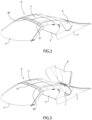
figure 1 is a schematic plan view, with parts removed for greater clarity, of a sports car provided with a preferred embodiment of the openable roof according to the present invention; -
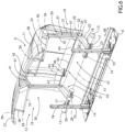
figures 2, 3 ,4 and 5 are four schematic perspective views, with parts removed for greater clarity, of a detail of the sports car offigure 1 shown in four different operating positions; -
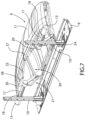
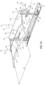
figures 6 ,7 and8 are three schematic perspective views, with parts removed for greater clarity, of a detail offigures 2, 3 ,4 and 5 shown in three different operating positions; and -
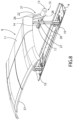
figures 9 ,10 and11 are three schematic perspective views, with parts removed for greater clarity, of a detail offigures 6 ,7 and8 shown in three different operating positions. - With reference to
figure 1 , number 1 indicates, as a whole, a sports car comprising anouter body 2 having a shape that is tapered towards the back of the car 1 and apassenger compartment 3 projecting upwards from a lower floor of the car 1 in order to accommodate, on the inside, at least the driver of the car 1. - The
passenger compartment 3 is closed by afront windshield 4, by a rear windshield 5 (figures 4 and 5 ) and by anopenable roof 6. - The
roof 6 comprises a containingtank 7, which is obtained at the back of thepassenger compartment 3 and has, in plan view, the shape of a trapezium arranged with its larger base between thepassenger compartment 3 and a smaller base of its. - The
tank 7 is closed by alid 8 coupled to thebody 2 in a rotary manner so as to move between a closing position (figures 2 and5 ) and an opening position (figures 3 and4 ) closing and opening thetank 7. - The
roof 6 further has asupport frame 9, which is integrated in thebody 2 and is provided with twovertical uprights 10 parallel to one another and projecting into thetank 7. - According to
figures 2 to 11 , theroof 6 further comprises afabric cover 11 to close thepassenger compartment 3 at the top and anoperating unit 12 to move thecover 11 between an opening position, in which thecover 11 is arranged inside thetank 7 in order to open theroof 6, and a closing position, in which thecover 11 is arranged on the outside of thetank 7 in order to close theroof 6. - The
operating unit 12 comprises twoelectric motors 13, which are aligned with and face one another and haverespective output shafts 14 mounted so as to rotate around acommon rotation axis 15, which is substantially transverse to adriving direction 16 of the car 1. - Each
motor 13 is fixed to asleeve 17, which is coaxial to theaxis 15, extends around therelative shaft 14 and is fixed, in turn, to a relative upright 10. - Each
sleeve 17 has ahelical guide 18, which is obtained through thesleeve 17 and is wound like a spiral around and along saidaxis 15. - The
unit 12 further comprises twolever mechanisms 19 parallel to one another, each associated with arelative motor 13 and comprising acollar 20, which is fitted on therelative sleeve 17 coaxial to theaxis 15 and is coupled to therelative shaft 14 by means of a screw-nut screw coupling, in particular by means of a recirculating ball coupling, and is further coupled to theguide 18 of thesleeve 17 so as to move, with a rotation-translation movement, along and around theaforesaid axis 15. - The
collar 20 defines the first member of a first articulated quadrilateral 21 further comprising asecond member 22 with an elongated shape coupled in a rotary manner, on one side, to thecollar 20 so as to rotate, relative to thecollar 20, around arotation axis 23 parallel to theaxis 15 and, on the other side, to athird member 24 of the first articulated quadrilateral 21 so as to rotate, relative to themember 24, around arotation axis 25 parallel to theaxis 15. - The articulated quadrilateral 21 further comprises a
fourth member 26, which is defined by a first arm of arocker arm 27 and extends between tworotation axes axis 15, theaxis 28 being the rotation axis between thecollar 20 and themember 26 and theaxis 29 being the rotation axis between therocker arm 27 and themember 24. - The
member 24 defines the first member of a second articulated quadrilateral 30 comprising, in addition, asecond member 31 with an elongated shape coupled in a rotary manner, on one side, to themember 24 so as to rotate, relative to themember 24, around arotation axis 32 parallel to theaxis 15 and, on the other side, to athird member 33 of the second articulated quadrilateral 30 so as to rotate, relative to themember 33, around arotation axis 34 parallel to theaxis 15. - The second articulated quadrilateral 30 further comprises a
fourth member 35, which is defined by a second arm of therocker arm 27 and extends between theaxis 29 and arotation axis 36 of themember 35 relative to themember 33. - The
members 33 of the twolever mechanisms 19 have an elongated shape, project from the second articulated quadrilateral 30 and have respective free ends connected to afront bar 37 of theoperating unit 12. - Each
member 33 is connected to thebar 37 through the interposition of a connectingrod 38, which extends between tworotation axes 39 transverse to theaxis 15, one of them being the rotation axis of the connectingrod 38 relative to themember 33 and the other one being the rotation axis of the connectingrod 38 relative to thebar 37. - The
bar 37 is configured to be coupled to asupport ring 40 of thefront windshield 4 following the movement of thecover 11 to its closing position. - The
operating unit 12 further comprises, in this specific case, twostiffening cross members 41 with a variable length to connect the twolever mechanisms 19 to one another. - Each
cross member 41 comprises, in this specific case, acrank mechanism 42 comprising, in turn, acentral connecting rod 43 and twoside cranks 44, each extending between tworotation axes axis 15, theaxis 45 being the rotation axis of thecrank 44 relative to the connectingrod 43 and theaxis 46 being the rotation axis of thecrank 44 relative to acoupling bracket 47 shaped so as to project from therocker arm 27 of arelative lever mechanism 19 towards theother lever mechanism 19. - With regard to what disclosed above, it should finally be pointed out that the
cover 11 is coupled to thefront bar 37 and to thelever mechanisms 19. - In use, the activation of the
electric motors 13 leads to the rotation of therelative output shafts 14 and, hence, to the rotation-translation movement of thecollars 20 along and around saidaxis 15. - The combination of the movement of the
collars 20 in a movingdirection 48 parallel to theaxis 15 with the movement of thecollars 20 around theaxis 15 leads to the movement of thelever mechanisms 19 between a wide position (figures 8 and10 ), in which thelever mechanisms 19 are arranged on the outside of the containingtank 7 and at a distance D1 from one another measured parallel to thedirection 48, and a narrow position (figures 7 and9 ), in which thelever mechanisms 19 are arranged inside the containingtank 7 and at a distance D2 from one another, also measured parallel to thedirection 48, that is smaller than both the distance D1 and the minimum width of thetank 7. - As a consequence, the
lever mechanisms 19 and thecover 11 are movable between the opening position of the roof 6 (figure 7 ), in which thelever mechanisms 19 get closer to one another in thedirection 48 in order to get into thetank 7 and store thecover 11 in a U-shaped configuration inside thetank 7, and the closing position of the roof 6 (figure 8 ), in which thelever mechanisms 19 move away from one another in thedirection 48 in order to place themselves on the outside of thetank 7 and move thecover 11 to a spread configuration on the outside of thetank 7. - According to a variant which is not shown herein, the
crank mechanisms 42 are eliminated and replaced by respective telescopic bars.
Claims (13)
- An openable roof for sports cars, the roof comprising a containing tank (7); a fabric cover (11); and an operating unit (12) to move the fabric cover (11) between an opening position, in which the fabric cover (11) is housed inside the containing tank (7) in order to open the roof, and a closing position, in which the fabric cover (11) extends on the outside of the containing tank (7) in order to close the roof; the operating unit (12) comprising two lever mechanisms (19), which are parallel to one another and to a driving direction (16) of the sports car, and a front bar (37), which extends between the two lever mechanisms (19) and is configured to be coupled to a support ring (40) of a front windshield (4) of the sports car following the movement of the fabric cover (11) to its closing position; the fabric cover (11) being fixed to the front bar (37) and to the two lever mechanisms (19); and being characterized in that the two lever mechanisms (19) are movable relative to one another in a moving direction (48), which is transverse to the driving direction (16) of the sports car, between a narrow position, in which the lever mechanisms (19) are arranged inside the containing tank (7) following the movement of the fabric cover (11) to its opening position, and a wide position, in which the lever mechanisms (19) extend on the outside of the containing tank (7) following the movement of the fabric cover (11) to its closing position.
- The openable roof according to claim 1, wherein the distance (D2) between the lever mechanisms (19) arranged in their narrow position, which is measured parallel to the moving direction (48), is smaller than the distance (D1) between the lever mechanisms (19) arranged in their wide position and than the minimum width of the containing tank (7), which are also measured parallel to the moving direction (48) .
- The openable roof according to claim 1 or 2, wherein the operating unit (12) further comprises at least one stiffening cross member (41) with a variable length interposed between the lever mechanisms (19) in order to connect the lever mechanisms (19) to one another.
- The openable roof according to claim 3, wherein the stiffening cross member (41) comprises a telescopic bar or a crank mechanism (42).
- The openable roof according to any one of the preceding claims, wherein the operating unit (12) comprises, for each lever mechanism (19), a respective actuator device (13) to move the lever mechanism (19) in the moving direction (48) between its narrow and wide positions.
- The openable roof according to claim 5, wherein each lever mechanism (19) comprises a first articulated quadrilateral (21) connected to the relative actuator device (13) and a second articulated quadrilateral (30) interposed between the first articulated quadrilateral (21) and the front bar (37).
- The openable roof according to claim 6, wherein each actuator device (13) comprises an electric motor provided with an output shaft (14) mounted so as to rotate around a rotation axis (15), which is substantially parallel to the moving direction (48); the first articulated quadrilateral (21) of each lever mechanism (19) comprising a first member (20) coupled to the output shaft (14) of the relative electric motor so as to move with a rotation-translation motion along and around said rotation axis (15).
- The openable roof according to claim 7, wherein the first articulated quadrilateral (21) further comprises a second member (22) and a third member (26), which are connected to the first member (20) in a rotary manner, and a fourth member (24), which is connected to said second and third member (22, 26) in a rotary manner.
- The openable roof according to claim 8, wherein the second articulated quadrilateral (30) comprises a fifth and a sixth member (31, 35), which are connected to the fourth member (24) in a rotary manner, and a seventh member (33), which is connected to said fifth and sixth member (31, 35) in a rotary manner and projects from the second articulated quadrilateral (30); the front bar (37) being connected to the seventh members (33) of the two lever mechanisms (19).
- The openable roof according to claim 9, wherein the front bar (37) is coupled to the seventh member (33) of each second articulated quadrilateral (30) through the interposition of a relative connecting rod (38) coupled to the seventh member (33) and to the front bar (37) in a rotary manner.
- The openable roof according to any one of the claims from 7 to 10, wherein the operating unit (12) further comprises, for each electric motor, a respective helical guide (18), which extends around the output shaft (14) of the electric motor, is wound like a spiral around and along said rotation axis (15) and is engaged with a rotation-translation motion by the first member (20) of the relative first articulated quadrilateral (21).
- The openable roof according to any one of the preceding claims, wherein the fabric cover (11) has, when the roof is closed, a spread configuration and further has, when the roof is open, a U-folded configuration inside the containing tank (7).
- The openable roof according to any one of the preceding claims, wherein the containing tank (7) has, in plan view, a substantially trapezoid-like shape.
Applications Claiming Priority (1)
| Application Number | Priority Date | Filing Date | Title |
|---|---|---|---|
| IT102023000000606A IT202300000606A1 (en) | 2023-01-17 | 2023-01-17 | OPEN ROOF FOR SPORTS CARS |
Publications (2)
| Publication Number | Publication Date |
|---|---|
| EP4403392A1 true EP4403392A1 (en) | 2024-07-24 |
| EP4403392B1 EP4403392B1 (en) | 2026-01-14 |
Family
ID=85792223
Family Applications (1)
| Application Number | Title | Priority Date | Filing Date |
|---|---|---|---|
| EP24151778.8A Active EP4403392B1 (en) | 2023-01-17 | 2024-01-15 | Openable roof for sports cars |
Country Status (3)
| Country | Link |
|---|---|
| US (1) | US20240239164A1 (en) |
| EP (1) | EP4403392B1 (en) |
| IT (1) | IT202300000606A1 (en) |
Citations (3)
| Publication number | Priority date | Publication date | Assignee | Title |
|---|---|---|---|---|
| FR473167A (en) * | 1914-06-08 | 1915-01-05 | Oswald Viertel | Hood body folds up invisibly |
| FR1382296A (en) * | 1963-11-07 | 1964-12-18 | Applic Ind Soc Et | Convertible vehicle |
| US5620226A (en) * | 1995-12-07 | 1997-04-15 | Dura Convertible Systems, Inc. | Simplified automated top operator |
-
2023
- 2023-01-17 IT IT102023000000606A patent/IT202300000606A1/en unknown
-
2024
- 2024-01-09 US US18/408,091 patent/US20240239164A1/en active Pending
- 2024-01-15 EP EP24151778.8A patent/EP4403392B1/en active Active
Patent Citations (3)
| Publication number | Priority date | Publication date | Assignee | Title |
|---|---|---|---|---|
| FR473167A (en) * | 1914-06-08 | 1915-01-05 | Oswald Viertel | Hood body folds up invisibly |
| FR1382296A (en) * | 1963-11-07 | 1964-12-18 | Applic Ind Soc Et | Convertible vehicle |
| US5620226A (en) * | 1995-12-07 | 1997-04-15 | Dura Convertible Systems, Inc. | Simplified automated top operator |
Also Published As
| Publication number | Publication date |
|---|---|
| EP4403392B1 (en) | 2026-01-14 |
| US20240239164A1 (en) | 2024-07-18 |
| IT202300000606A1 (en) | 2024-07-17 |
Similar Documents
| Publication | Publication Date | Title |
|---|---|---|
| JP4268762B2 (en) | Retractable roof for hose box, panel truck or station wagon type vehicle | |
| US6029873A (en) | Retractable roof rack | |
| US8118343B2 (en) | Stowable roof configuration for a convertible | |
| US5758923A (en) | Folding top for a passenger vehicle | |
| US20070187985A1 (en) | Vehicle roof automatic opening/closing device | |
| US20120025582A1 (en) | Seat assembly having an adjustable head restraint assembly | |
| US6948757B2 (en) | Wind shield for motorbikes and drive device for a vehicle component | |
| US7644974B2 (en) | Hood for a convertible | |
| EP1842710A2 (en) | Retractable roof and vehicle therewith | |
| JP2005529782A5 (en) | ||
| JP4689930B2 (en) | Retractable hardtop system for convertible cars | |
| EP4403392A1 (en) | Openable roof for sports cars | |
| KR102950072B1 (en) | Armrest for vehicle | |
| US6631939B2 (en) | Adjustable vehicle roof having a pivotable side window | |
| US12110724B2 (en) | Actuator for vehicle flap | |
| US8733821B2 (en) | Trim arrangement for a pivot arm of a motor vehicle door | |
| EP2065240B1 (en) | Vehicle roof opening/closing apparatus | |
| WO2010034247A1 (en) | Retractable vehicle roof apparatus and vehicle having the same | |
| KR20030046824A (en) | Auxiliary seat for bus | |
| JP7752751B2 (en) | Device for vehicle roof and vehicle roof | |
| JP4681182B2 (en) | Wind wiper device for vehicle and method for operating wiper lever linkage | |
| KR20180137987A (en) | Seat Bolster Structure of Vehicle | |
| US7681938B2 (en) | Convertible vehicle | |
| JPH03501378A (en) | Special wiper system for automobiles | |
| CN209719441U (en) | A kind of power fold mechanism in automobile |
Legal Events
| Date | Code | Title | Description |
|---|---|---|---|
| PUAI | Public reference made under article 153(3) epc to a published international application that has entered the european phase |
Free format text: ORIGINAL CODE: 0009012 |
|
| STAA | Information on the status of an ep patent application or granted ep patent |
Free format text: STATUS: THE APPLICATION HAS BEEN PUBLISHED |
|
| AK | Designated contracting states |
Kind code of ref document: A1 Designated state(s): AL AT BE BG CH CY CZ DE DK EE ES FI FR GB GR HR HU IE IS IT LI LT LU LV MC ME MK MT NL NO PL PT RO RS SE SI SK SM TR |
|
| STAA | Information on the status of an ep patent application or granted ep patent |
Free format text: STATUS: REQUEST FOR EXAMINATION WAS MADE |
|
| 17P | Request for examination filed |
Effective date: 20241122 |
|
| RBV | Designated contracting states (corrected) |
Designated state(s): AL AT BE BG CH CY CZ DE DK EE ES FI FR GB GR HR HU IE IS IT LI LT LU LV MC ME MK MT NL NO PL PT RO RS SE SI SK SM TR |
|
| RIC1 | Information provided on ipc code assigned before grant |
Ipc: B60J 7/12 20060101AFI20250710BHEP Ipc: B60J 7/14 20060101ALN20250710BHEP |
|
| GRAP | Despatch of communication of intention to grant a patent |
Free format text: ORIGINAL CODE: EPIDOSNIGR1 |
|
| STAA | Information on the status of an ep patent application or granted ep patent |
Free format text: STATUS: GRANT OF PATENT IS INTENDED |
|
| RIC1 | Information provided on ipc code assigned before grant |
Ipc: B60J 7/12 20060101AFI20250717BHEP Ipc: B60J 7/14 20060101ALN20250717BHEP |
|
| INTG | Intention to grant announced |
Effective date: 20250818 |
|
| GRAS | Grant fee paid |
Free format text: ORIGINAL CODE: EPIDOSNIGR3 |
|
| GRAA | (expected) grant |
Free format text: ORIGINAL CODE: 0009210 |
|
| STAA | Information on the status of an ep patent application or granted ep patent |
Free format text: STATUS: THE PATENT HAS BEEN GRANTED |
|
| AK | Designated contracting states |
Kind code of ref document: B1 Designated state(s): AL AT BE BG CH CY CZ DE DK EE ES FI FR GB GR HR HU IE IS IT LI LT LU LV MC ME MK MT NL NO PL PT RO RS SE SI SK SM TR |
|
| REG | Reference to a national code |
Ref country code: CH Ref legal event code: F10 Free format text: ST27 STATUS EVENT CODE: U-0-0-F10-F00 (AS PROVIDED BY THE NATIONAL OFFICE) Effective date: 20260114 Ref country code: GB Ref legal event code: FG4D |
|
| REG | Reference to a national code |
Ref country code: DE Ref legal event code: R096 Ref document number: 602024001965 Country of ref document: DE |
|
| REG | Reference to a national code |
Ref country code: IE Ref legal event code: FG4D |
|
| PGFP | Annual fee paid to national office [announced via postgrant information from national office to epo] |
Ref country code: DE Payment date: 20260127 Year of fee payment: 3 |
|
| PGFP | Annual fee paid to national office [announced via postgrant information from national office to epo] |
Ref country code: AT Payment date: 20260301 Year of fee payment: 3 |
|
| PGFP | Annual fee paid to national office [announced via postgrant information from national office to epo] |
Ref country code: IT Payment date: 20260131 Year of fee payment: 3 |
|
| PGFP | Annual fee paid to national office [announced via postgrant information from national office to epo] |
Ref country code: FR Payment date: 20260126 Year of fee payment: 3 |