EP4403365A1 - Liquid ejection head - Google Patents
Liquid ejection head Download PDFInfo
- Publication number
- EP4403365A1 EP4403365A1 EP23205643.2A EP23205643A EP4403365A1 EP 4403365 A1 EP4403365 A1 EP 4403365A1 EP 23205643 A EP23205643 A EP 23205643A EP 4403365 A1 EP4403365 A1 EP 4403365A1
- Authority
- EP
- European Patent Office
- Prior art keywords
- sidewalls
- pair
- air chamber
- head according
- cover member
- Prior art date
- Legal status (The legal status is an assumption and is not a legal conclusion. Google has not performed a legal analysis and makes no representation as to the accuracy of the status listed.)
- Pending
Links
- 239000007788 liquid Substances 0.000 title claims abstract description 27
- 239000011800 void material Substances 0.000 claims abstract description 39
- 229920005989 resin Polymers 0.000 claims description 22
- 239000011347 resin Substances 0.000 claims description 22
- 239000000463 material Substances 0.000 claims description 16
- 239000000976 ink Substances 0.000 description 73
- 239000000758 substrate Substances 0.000 description 22
- 239000010408 film Substances 0.000 description 8
- 230000008602 contraction Effects 0.000 description 6
- PXHVJJICTQNCMI-UHFFFAOYSA-N Nickel Chemical compound [Ni] PXHVJJICTQNCMI-UHFFFAOYSA-N 0.000 description 4
- 238000004519 manufacturing process Methods 0.000 description 4
- 238000005452 bending Methods 0.000 description 3
- 230000015572 biosynthetic process Effects 0.000 description 3
- 239000003086 colorant Substances 0.000 description 3
- 230000006866 deterioration Effects 0.000 description 3
- 238000007639 printing Methods 0.000 description 3
- 239000000853 adhesive Substances 0.000 description 2
- 230000001070 adhesive effect Effects 0.000 description 2
- 230000007423 decrease Effects 0.000 description 2
- 238000010586 diagram Methods 0.000 description 2
- 238000006073 displacement reaction Methods 0.000 description 2
- 230000006870 function Effects 0.000 description 2
- 229910052451 lead zirconate titanate Inorganic materials 0.000 description 2
- 229910052759 nickel Inorganic materials 0.000 description 2
- 239000010409 thin film Substances 0.000 description 2
- 229910000990 Ni alloy Inorganic materials 0.000 description 1
- 239000004642 Polyimide Substances 0.000 description 1
- PNEYBMLMFCGWSK-UHFFFAOYSA-N aluminium oxide Inorganic materials [O-2].[O-2].[O-2].[Al+3].[Al+3] PNEYBMLMFCGWSK-UHFFFAOYSA-N 0.000 description 1
- 239000000919 ceramic Substances 0.000 description 1
- 238000006243 chemical reaction Methods 0.000 description 1
- 239000000470 constituent Substances 0.000 description 1
- 230000001419 dependent effect Effects 0.000 description 1
- 238000007599 discharging Methods 0.000 description 1
- 229920006332 epoxy adhesive Polymers 0.000 description 1
- HFGPZNIAWCZYJU-UHFFFAOYSA-N lead zirconate titanate Chemical compound [O-2].[O-2].[O-2].[O-2].[O-2].[Ti+4].[Zr+4].[Pb+2] HFGPZNIAWCZYJU-UHFFFAOYSA-N 0.000 description 1
- 238000003754 machining Methods 0.000 description 1
- 230000005499 meniscus Effects 0.000 description 1
- 238000012986 modification Methods 0.000 description 1
- 230000004048 modification Effects 0.000 description 1
- 239000002245 particle Substances 0.000 description 1
- 230000010287 polarization Effects 0.000 description 1
- 229920001721 polyimide Polymers 0.000 description 1
- 238000007789 sealing Methods 0.000 description 1
- 238000006467 substitution reaction Methods 0.000 description 1
- 229920005992 thermoplastic resin Polymers 0.000 description 1
- 229920001187 thermosetting polymer Polymers 0.000 description 1
- XLYOFNOQVPJJNP-UHFFFAOYSA-N water Substances O XLYOFNOQVPJJNP-UHFFFAOYSA-N 0.000 description 1
Images




Classifications
-
- B—PERFORMING OPERATIONS; TRANSPORTING
- B41—PRINTING; LINING MACHINES; TYPEWRITERS; STAMPS
- B41J—TYPEWRITERS; SELECTIVE PRINTING MECHANISMS, i.e. MECHANISMS PRINTING OTHERWISE THAN FROM A FORME; CORRECTION OF TYPOGRAPHICAL ERRORS
- B41J2/00—Typewriters or selective printing mechanisms characterised by the printing or marking process for which they are designed
- B41J2/005—Typewriters or selective printing mechanisms characterised by the printing or marking process for which they are designed characterised by bringing liquid or particles selectively into contact with a printing material
- B41J2/01—Ink jet
- B41J2/135—Nozzles
- B41J2/14—Structure thereof only for on-demand ink jet heads
- B41J2/14201—Structure of print heads with piezoelectric elements
- B41J2/14209—Structure of print heads with piezoelectric elements of finger type, chamber walls consisting integrally of piezoelectric material
-
- B—PERFORMING OPERATIONS; TRANSPORTING
- B41—PRINTING; LINING MACHINES; TYPEWRITERS; STAMPS
- B41J—TYPEWRITERS; SELECTIVE PRINTING MECHANISMS, i.e. MECHANISMS PRINTING OTHERWISE THAN FROM A FORME; CORRECTION OF TYPOGRAPHICAL ERRORS
- B41J2/00—Typewriters or selective printing mechanisms characterised by the printing or marking process for which they are designed
- B41J2/005—Typewriters or selective printing mechanisms characterised by the printing or marking process for which they are designed characterised by bringing liquid or particles selectively into contact with a printing material
- B41J2/01—Ink jet
- B41J2/135—Nozzles
- B41J2/14—Structure thereof only for on-demand ink jet heads
- B41J2/14201—Structure of print heads with piezoelectric elements
-
- B—PERFORMING OPERATIONS; TRANSPORTING
- B41—PRINTING; LINING MACHINES; TYPEWRITERS; STAMPS
- B41J—TYPEWRITERS; SELECTIVE PRINTING MECHANISMS, i.e. MECHANISMS PRINTING OTHERWISE THAN FROM A FORME; CORRECTION OF TYPOGRAPHICAL ERRORS
- B41J2/00—Typewriters or selective printing mechanisms characterised by the printing or marking process for which they are designed
- B41J2/005—Typewriters or selective printing mechanisms characterised by the printing or marking process for which they are designed characterised by bringing liquid or particles selectively into contact with a printing material
- B41J2/01—Ink jet
- B41J2/135—Nozzles
- B41J2/14—Structure thereof only for on-demand ink jet heads
-
- B—PERFORMING OPERATIONS; TRANSPORTING
- B41—PRINTING; LINING MACHINES; TYPEWRITERS; STAMPS
- B41J—TYPEWRITERS; SELECTIVE PRINTING MECHANISMS, i.e. MECHANISMS PRINTING OTHERWISE THAN FROM A FORME; CORRECTION OF TYPOGRAPHICAL ERRORS
- B41J2/00—Typewriters or selective printing mechanisms characterised by the printing or marking process for which they are designed
- B41J2/005—Typewriters or selective printing mechanisms characterised by the printing or marking process for which they are designed characterised by bringing liquid or particles selectively into contact with a printing material
- B41J2/01—Ink jet
- B41J2/135—Nozzles
- B41J2/14—Structure thereof only for on-demand ink jet heads
- B41J2002/14362—Assembling elements of heads
-
- B—PERFORMING OPERATIONS; TRANSPORTING
- B41—PRINTING; LINING MACHINES; TYPEWRITERS; STAMPS
- B41J—TYPEWRITERS; SELECTIVE PRINTING MECHANISMS, i.e. MECHANISMS PRINTING OTHERWISE THAN FROM A FORME; CORRECTION OF TYPOGRAPHICAL ERRORS
- B41J2/00—Typewriters or selective printing mechanisms characterised by the printing or marking process for which they are designed
- B41J2/005—Typewriters or selective printing mechanisms characterised by the printing or marking process for which they are designed characterised by bringing liquid or particles selectively into contact with a printing material
- B41J2/01—Ink jet
- B41J2/135—Nozzles
- B41J2/14—Structure thereof only for on-demand ink jet heads
- B41J2002/14459—Matrix arrangement of the pressure chambers
-
- B—PERFORMING OPERATIONS; TRANSPORTING
- B41—PRINTING; LINING MACHINES; TYPEWRITERS; STAMPS
- B41J—TYPEWRITERS; SELECTIVE PRINTING MECHANISMS, i.e. MECHANISMS PRINTING OTHERWISE THAN FROM A FORME; CORRECTION OF TYPOGRAPHICAL ERRORS
- B41J2202/00—Embodiments of or processes related to ink-jet or thermal heads
- B41J2202/01—Embodiments of or processes related to ink-jet heads
- B41J2202/11—Embodiments of or processes related to ink-jet heads characterised by specific geometrical characteristics
-
- B—PERFORMING OPERATIONS; TRANSPORTING
- B41—PRINTING; LINING MACHINES; TYPEWRITERS; STAMPS
- B41J—TYPEWRITERS; SELECTIVE PRINTING MECHANISMS, i.e. MECHANISMS PRINTING OTHERWISE THAN FROM A FORME; CORRECTION OF TYPOGRAPHICAL ERRORS
- B41J2202/00—Embodiments of or processes related to ink-jet or thermal heads
- B41J2202/01—Embodiments of or processes related to ink-jet heads
- B41J2202/12—Embodiments of or processes related to ink-jet heads with ink circulating through the whole print head
Definitions
- Embodiments described herein relate generally to a liquid ejection head.
- a share-mode shared-wall inkjet head generally adopts so-called three-cycle driving for sharing the same driving element in two pressure chambers and simultaneously driving one third of a plurality of arrayed chambers as pressure chambers.
- An independent driving head is also developed that uses both sides of a pressure chamber to be driven as dummy pressure chambers and drives one pressure chamber with independent two driving elements.
- a structure is also developed in which a large number of grooves are formed in a piezoelectric body, entrances of the grooves are closed by photosensitive resin walls or the like at every other grooves, and the grooves not closed in the entrances are used as pressure chambers and the closed grooves are used as air chambers to perform independent driving.
- a liquid ejection head comprising a plurality of sidewalls forming a plurality of grooves that alternately configure a plurality of pressure chambers and a plurality of air chambers; and a cover member including an inner wall section formed between a pair of the sidewalls configuring both sides of each of the air chambers and an outer wall section disposed further on an outer side than end portions of the pair of sidewalls, the cover member including a void section in at least a part thereof and closing an opening end portion of the air chamber.
- An object of embodiments is to provide a liquid ejection head that can ensure a satisfactory ejection characteristic.
- a liquid ejection head includes a plurality of sidewalls and a cover member.
- the plurality of sidewalls form a plurality of grooves that alternately configure a plurality of pressure chambers and a plurality of air chambers.
- the cover member includes an inner wall section formed between a pair of the sidewalls configuring both sides of each of the air chambers and an outer wall section disposed further on an outer side than end portions of the pair of sidewalls.
- the cover member includes a void section in at least a part thereof and closes an opening end portion of the air chamber.
- FIG. 1 is a perspective view illustrating an inkjet head according to the first embodiment.
- FIG. 2 is an exploded perspective view of a part of the inkjet head.
- FIG. 3 is a perspective view illustrating a configuration of a part of the inkjet head in an enlarged form.
- FIGS. 4 to 7 are sectional views illustrating configurations of parts of the inkjet head in an enlarged form.
- FIG. 8 is an explanatory diagram of a driving state.
- X, Y, and Z in the figures respectively indicate a first direction, a second direction, and a third direction orthogonal to one another.
- directions are explained based on a posture in which a parallel arrangement direction of nozzles 28 and pressure chambers 31 of the inkjet head 10 extends along an X axis, an extending direction of the pressure chambers 31 is along a Y axis, and an ejecting direction of liquid is along a Z axis.
- the directions are not limited to these directions.
- the inkjet head 10 is a share-mode shared-wall inkjet head of a so-called side shooter type.
- the inkjet head 10 is a device for ejecting ink and is mounted, for example, on the inside of an inkjet printer.
- the inkjet head 10 is an inkjet head of an independent driving type in which the pressure chambers 31 and air chambers 32 are alternately disposed.
- the air chambers 32 are air chambers to which ink is not supplied and do not include the nozzles 28.
- the inkjet head 10 includes an actuator base 11, a nozzle plate 12, and a frame 13.
- the actuator base 11 is an example of a base material.
- An ink chamber 27 to which ink, which is an example of liquid, is supplied is formed on the inside of the inkjet head 10.
- the inkjet head 10 includes components such as a circuit board 17 that controls the inkjet head 10 and a manifold 18 that forms a part of a path between the inkjet head 10 and an ink tank.
- the actuator base 11 includes a substrate 21 and a pair of actuators 22.
- the substrate 21 is formed in a rectangular plate shape by ceramics such as alumina.
- the substrate 21 includes a flat mounting surface.
- the pair of actuators 22 is bonded to the mounting surface of the substrate 21.
- a plurality of supply holes 25 and a plurality of discharge holes 26 are formed in the substrate 21.
- pattern wires 211 are formed on the substrate 21 of the actuator base 11.
- the pattern wires 211 are formed by, for example, a nickel thin film.
- the pattern wires 211 include a common pattern and an individual pattern and are configured in a predetermined pattern shape connected to electrode layers 34 formed in the actuators 22.
- the pattern wires 211 are formed in positions avoiding the supply holes 25 and the discharge holes 26.
- the supply holes 25 are provided side by side in the longitudinal direction of the actuators 22 between the pair of actuators 22 in the center of the substrate 21.
- the supply holes 25 communicate with an ink supply section of the manifold 18.
- the supply holes 25 are connected to the ink tank via the ink supply section.
- the supply holes 25 supply the ink in the ink tank to the ink chamber 27.
- the discharge holes 26 are provided side by side in two rows across the supply holes 25 and the pair of actuators 22.
- the discharge holes 26 communicate with an ink discharge section of the manifold 18.
- the discharge holes 26 are connected to the ink tank via the ink discharge section.
- the discharge holes 26 discharge the ink in the ink chamber 27 to the ink tank.
- the pair of actuators 22 is bonded to the mounting surface of the substrate 21.
- the pair of actuators 22 is provided on the substrate 21 side by side in two rows across the supply holes 25.
- Each of the actuators 22 is formed by plate-like two piezoelectric bodies formed by, for example, lead zirconate titanate (PZT).
- PZT lead zirconate titanate
- the two piezoelectric bodies are pasted together such that polarization directions thereof are directions opposite to each other with respect to the thickness direction thereof.
- the actuators 22 are bonded to the mounting surface of the substrate 21 by, for example, an epoxy adhesive having a thermosetting property.
- the actuators 22 are disposed side by side in parallel in the ink chamber 27 to correspond to the nozzles 28 disposed side by side in two rows.
- the actuators 22 divide the ink chamber 27 into a first common chamber 271 in which the supply holes 25 are opened and two second common chambers 272 in which the discharge holes 26 are opened.
- the width in the latitudinal direction of the actuator 22 gradually increases from the top side toward the substrate side.
- a sectional shape in a direction (the latitudinal direction) orthogonal to the longitudinal direction of the actuator 22 is formed in a trapezoidal shape.
- a side surface section 221 of the actuator 22 includes inclined surfaces inclined with respect to the second direction and the third direction.
- the top of the actuator 22 is bonded to the nozzle plate 12.
- the actuator 22 includes a plurality of pressure chambers 31 and a plurality of air chambers 32.
- the actuator 22 includes a plurality of sidewalls 33 functioning as driving elements and includes, among the plurality of sidewalls 33, grooves configuring the pressure chambers 31 and the air chambers 32. In other words, the sidewalls 33 function as columnar driving elements formed among the grooves forming the pressure chambers 31 and the air chambers 32.
- FIG. 4 is a sectional view in which one of the actuators 22 of the inkjet head 10 illustrated in FIG. 2 is partially enlarged.
- FIG. 5 is a sectional view of the groove configuring the pressure chamber 31 of the inkjet head 10 illustrated in FIG. 4 taken along F5-F5.
- FIG. 6 is a sectional view of the groove configuring the air chamber 32 of the inkjet head 10 illustrated in FIG. 4 taken along F6-F6.
- the bottom surface section of the groove and the principal plane of the substrate 21 are connected by the inclined sidewall sections 221.
- the pressure chambers 31 and the air chambers 32 are alternately disposed.
- the pressure chambers 31 and the air chambers 32 respectively extend in a direction crossing the longitudinal direction of the actuator 22.
- the plurality of the pressure chambers 31 and the plurality of air chambers 32 are disposed in parallel in the first direction (the X axis in the figures), which is the longitudinal direction of the actuator 22.
- the width dimension in the X direction of the grooves is fixed in the depth direction extending in the Z direction.
- a cross section orthogonal to the Y direction, which is an extending direction of the grooves, is formed in a rectangular shape.
- a shape of the pressure chambers 31 and a shape of the air chambers 32 may be different.
- the sidewalls 33 are formed between the pressure chambers 31 and the air chambers 32 and deformed according to a driving signal to change the volume of the pressure chambers 31.
- the electrode layers 34 are respectively provided on the inner wall surfaces of the pressure chambers 31 and the air chambers 32 and the side surface section 221 of the actuator base 11.
- the electrode layers 34 are formed by a conductive film such as a nickel thin film.
- the electrode layers 34 lead from the inner surface sections of the grooves onto the substrate 21 through the side surface section 221 and are connected to the pattern wires 211.
- the electrode layers 34 are formed on at least one of the side surface sections and the bottom surface sections of the sidewalls 33.
- the plurality of pressure chambers 31 communicate with the plurality of nozzles 28 of the nozzle plate 12 bonded to the tops of the pressure chambers 31. Both ends in the second direction of each of the pressure chambers 31 communicate with the ink chamber 27. That is, one end portion is opened to the first common chamber 271 of the ink chamber 27 and the other end portion is opened to the second common chambers 272 of the ink chamber 27. Therefore, ink flows in from one end portion of the pressure chamber 31 and flows out from the other end portion. The ink may flows in from both the end portions of the pressure chamber 31.
- one side in the third direction (the Z direction) of the air chamber 32 is closed by the nozzle plate 12 bonded to the top of the air chamber 32.
- both the ends in the second direction of the plurality of air chambers 32 are closed by the cover members 23. That is, the cover members 23 are respectively disposed between the first common chamber 271 of the ink chamber 27 and the air chamber 32 and between the air chamber 32 and the second common chambers 272. Both ends of the air chamber 32 is separated from the ink chamber 27. Therefore, the air chamber 32 configures an air chamber into which ink does not flow.
- the cover members 23 are respectively provided at both the ends in the Y direction (the second direction), which is an extending direction of the air chambers 32.
- the cover members 23 connect end portions of the sidewalls 33 and separate the common chambers 271 and 272 and the air chamber 32.
- the cover members 23 include void sections 233 at least in a part of the cover members 23 and close an opening end portion of the air chamber 32.
- Each of the cover members 23 includes a pair of extending walls 231 extending in the extending direction of the air chamber 32 and a connecting wall 232 that connects the pair of extending walls 231 and includes the void section 233 formed between the pair of extending walls 231.
- the void section 233 smaller than the width between the pair of sidewalls 33 is formed between the pair of extending walls 231. That is, the pair of extending walls 231 is separated in the first direction (the X direction), which is a deforming direction of the pair of extending walls 231.
- the cover member 23 is formed in a reverse C shape or a U shape opened toward the outer side in the extending direction of the air chamber 32 in a plan view as illustrated in FIG. 4 .
- the pair of extending walls 231 is wall members extending in the extending direction and the depth direction of the subject air chamber 32.
- the pair of extending walls 231 integrally includes inner wall sections 234 formed on the inner surfaces of a pair of sidewalls configuring both the sides in an arranging direction of the air chambers 32 and outer wall sections 235 disposed further on the outer side than end portions of the pair of sidewalls.
- the pair of extending walls 231 is formed in a range from a counter surface of the nozzle plate 12 to the bottoms of the grooves over the entire length of the depth of the grooves in the Z direction (depth direction).
- the void section 233 is formed between the pair of extending walls 231.
- a width dimension in the X direction of the void section 233 is fixed over the entire length in the extending direction.
- the inner wall sections 234 have smaller thickness dimension in the arranging direction and are configured thinner than the outer wall sections 235 in the arranging direction.
- the void section 233 is a slit-like space having a width dimension smaller than the width dimension of the air chamber 32 in the width direction.
- the void section 233 is formed between the end portions of the sidewalls 33 on both the sides in the extending direction (for example, the void section 233 may partially extend into the air chamber 32 between the sidewalls 33).
- the void section 233 is formed over end portions of the pair of extending walls 231 from a position beside the end portions of the sidewalls 33 in a direction away from the air chamber 32 and the connecting wall 232 (for example, the void section 233 may partially extend outside the air chamber 32 between the sidewalls 33) .
- the void section 233 opened toward the outer side is formed to the connecting wall 232 provided further on the inner side than the end portions of the sidewalls 33.
- the connecting wall 232 is a wall-like member that closes the air chamber 32 in a position further on the inner side in the extending direction of the air chamber 32 than the end portions of the sidewalls 33.
- the connecting wall 232 is a wall member extending along a surface orthogonal to the longitudinal direction of the air chamber 32.
- the connecting wall 232 connects the end portions on the inner side of the pair of extending walls 231 in the arranging direction and is formed from the counter surface of the nozzle plate 12 to the bottoms of the grooves in the Z direction to cover the end portion of the air chamber 32.
- the cover member 23 is made of a material having hardness lower than the hardness of a piezoelectric material.
- the cover member 23 is made of a resin material softer than the sidewalls 33.
- the cover member 23 is made of a photosensitive resin material.
- the cover member 23 is formed by exposing the photosensitive resin to light and hardening the photosensitive resin in the shape of the cover member 23. Peeling of the cover member 23 by contraction stress at the time of the hardening can be prevented because the void section 233 is interposed between the pair of extending walls 231 separated from each other in the X direction, which is a vibrating direction of the sidewalls 33.
- the nozzle plate 12 is formed by, for example, a rectangular film made of polyimide.
- the nozzle plate 12 faces the mounting surface of the actuator base 11.
- a plurality of nozzles 28 piercing through the nozzle plate 12 in the thickness direction thereof are formed.
- the plurality of nozzles 28 are provided as many as the pressure chambers 31 and are disposed to respectively face the pressure chambers 31.
- the plurality of nozzles 28 are disposed in the first direction (the X direction) and arrayed in two rows to correspond to the pair of actuators 22.
- Each of the nozzles 28 is formed in a tubular shape, the axis of which extends in the third direction. For example, even if the diameter of the nozzles 28 is fixed, the nozzles 28 may have a shape reduced in diameter toward the center or the distal end portion thereof.
- the nozzles 28 are disposed to face halfway portions in the extending direction of the pressure chambers 31 formed in the pair of actuators 22 and respectively communicate with the pressure chambers 31.
- the nozzles 28 are disposed one by one in positions corresponding to the positions between both the end portions of the pressure chambers 31, for example, the longitudinal direction centers of the pressure chambers 31.
- the frame 13 is formed in a rectangular frame shape by, for example, a nickel alloy.
- the frame 13 is interposed between the mounting surface of the actuator base 11 and the nozzle plate 12.
- the frame 13 is bonded to the mounting surface of the actuator base 11 and the nozzle plate 12. That is, the nozzle plate 12 is attached to the actuator base 11 via the frame 13.
- the manifold 18 is bonded to a side of the actuator base 11 opposite to the nozzle plate 12.
- An ink supply section, which is a flow path communicating with the supply holes 25, and an ink discharge section, which is a flow path communicating with the discharge holes 26, are formed on the inside of the manifold 18.
- the circuit board 17 illustrated in FIG. 1 is a film carrier package (FCP).
- the circuit board 17 includes a film 51 on which a plurality of wires are formed, the film 51 being made of flexible resin, and a driving IC 52 connected to the plurality of wires of the film 51.
- the driving IC 52 is electrically connected to the electrode layers 34 via the wires of the film 51 and the pattern wires 211.
- the ink chamber 27 surrounded by the actuator base 11, the nozzle plate 12, and the frame 13 is formed. That is, the ink chamber 27 is formed between the actuator base 11 and the nozzle plate 12.
- the ink chamber 27 is partitioned into three sections in the second direction (the Y direction) by the two actuators 22 and includes the two second common chambers 272, which are common chambers in which the discharge holes 26 are opened, and the first common chamber 271, which is a common chamber in which the supply holes 25 are opened.
- the first common chamber 271 and the second common chambers 272 communicate with the plurality of pressure chambers 31.
- FIG. 7 is an enlarged sectional view of a portion where the inkjet head 10 illustrated in FIG. 2 is taken along F7-F7 in the longitudinal direction.
- FIG. 8 is a partially enlarged sectional view illustrating an example of a state in which the sidewalls 33 illustrated in FIG. 7 is subjected to share mode deformation.
- ink circulates between the ink tank and the ink chamber 27 through the supply holes 25, the pressure chambers 31, and the discharge holes 26.
- the driving IC 52 applies a driving voltage to the electrode layers 34 of the pressure chambers 31 via the wires of the film 51 according to, for example, a signal input from a control unit of the inkjet printer to thereby cause a potential difference between the electrode layers 34 of the pressure chambers 31 and the electrode layers 34 of the air chambers 32 to selectively subject the sidewalls 33 to share mode deformation.
- the driving IC 52 deforms the sidewalls 33 formed between the pressure chambers 31 and the air chambers 32 according to a driving signal to change the volume of the pressure chambers 31.
- the sidewalls 33 undergo the share mode deformation, whereby the volume of the pressure chambers 31 in which the electrode layers 34 are provided increases and the pressure in the pressure chambers 31 decreases. Consequently, the ink in the ink chamber 27 flows into the pressure chambers 31.
- the driving IC 52 applies a driving voltage having the opposite potential to the electrode layers 34 of the pressure chambers 31. Consequently, as indicated by an alternate long and two short dashes line in FIG. 8 , the sidewalls 33 undergo the share mode deformation, the volume of the pressure chambers 31 in which the electrode layers 34 are provided decreases, and the pressure in the pressure chambers 31 increases. Consequently, the ink in the pressure chambers 31 is pressurized and ejected from the nozzles 28.
- a method of manufacturing the inkjet head 10 is explained. First, a piezoelectric member, on which a plurality of grooves are formed, is stuck to the plate-like substrate 21 by an adhesive or the like, machining is applied to the piezoelectric member using a dicing saw, a slicer, or the like to mold the actuator base 11 having a predetermined external shape. Note that, for example, a block-like base member having thickness equivalent to a plurality of actuator bases 11 may be formed and then divided to manufacture the plurality of actuator bases 11 having a predetermined shape.
- the electrode layers 34 and the pattern wires 211 are formed on the inner surfaces of the grooves configuring the pressure chambers 31 and the air chambers 32 and the surface of the substrate 21. Consequently, the electrode layers 34 and the pattern wires 211 are respectively formed in predetermined parts on the surface of the actuator base 11.
- both the ends of the air chambers 32 are closed by forming the cover members 23 at the end portions of the air chambers 32.
- photosensitive resin is filled in the grooves configuring the air chambers 32 and target parts are hardened by exposure to form the cover members 23.
- parts to be the void sections 233 are removed to form the slit-like void sections 233 and photosensitive resin layers are molded in a reverse C shape, whereby the cover members 23 are formed.
- the actuator base 11 is assembled to the manifold 18 and the frame 13 is stuck to one surface of the substrate 21 of the actuator base 11 by an adhesive sheet of thermoplastic resin.
- the assembled frame 13, the tops of the sidewalls 33 of the actuators 22, and the surfaces of the cover members 23 on the nozzle plate 12 side are polished to be the same surface.
- the nozzle plate 12 is bonded and attached to the polished surfaces of the tops of the sidewalls 33, the frame 13, and the cover members 23.
- the nozzles 28 are positioned to face the pressure chambers 31.
- the driving IC 52 and the circuit board 17 are connected to, via a flexible printed board, the pattern wires 211 formed on the principal plane of the substrate 21 as illustrated in FIG. 1 , whereby the inkjet head 10 is completed.
- the inkjet printer 100 includes a housing 111, a medium supply unit 112, an image forming unit 113, a medium discharge unit 114, a conveying device 115, and a control unit 116.
- the inkjet printer 100 is a liquid ejecting device that performs image formation processing on paper P by, for example, ejecting liquid such as ink while conveying the paper P as a recording medium, which is an ejection target object, along a predetermined conveying path A leading from the medium supply unit 112 to the medium discharge unit 114 through the image forming unit 113.
- the housing 111 configures an outer frame of the inkjet printer 100.
- a discharge port for discharging the paper P to the outside is provided in a predetermined part of the housing 111.
- the medium supply unit 112 includes a plurality of paper feeding cassettes and is configured to be capable of stacking and storing pluralities of pieces of the paper P of various sizes.
- the medium discharge unit 114 includes a paper discharge tray configured to be capable of holding the paper P discharged from the discharge port.
- the image forming unit 113 includes a supporting section 117 that supports the paper P and a plurality of head units 130 disposed to face one another above the supporting section 117.
- the supporting section 117 includes a conveying belt 118 provided in a loop shape in a predetermined region where image formation is performed, a support plate 119 that supports the conveying belt 118 from the rear side thereof, and a plurality of belt rollers 120 provided on the rear side of the conveying belt 118.
- the supporting section 117 supports the paper P on a holding surface, which is the upper surface of the conveying belt 118, and feeds the conveying belt 118 at predetermined timing according to rotation of the belt rollers 120 to thereby convey the paper P to a downstream side.
- the head units 130 include a plurality of inkjet heads 10 (for four colors), ink tanks 132 functioning as liquid tanks respectively mounted on the inkjet heads 10, connection flow paths 133 that connect the inkjet heads 10 and the ink tanks 132, and circulation pumps 134, which are circulating units.
- the head units 130 are circulation-type head units that always circulate liquid in the ink tanks 132 and the pressure chambers 31, the air chambers 32, and the ink chambers 27 fabricated on the inside of the inkjet head 10.
- the head units 130 include the inkjet heads 10 for four colors of cyan, magenta, yellow, and black and the ink tanks 132 that respectively store inks of these colors.
- the ink tanks 132 are connected to the inkjet heads 10 by the connection flow paths 133.
- the connection flow paths 133 includes supply flow paths connected to supply ports of the inkjet heads 10 and collection flow paths connected to discharge ports of the inkjet heads 10.
- Not-illustrated negative pressure control devices such as pumps are coupled to the ink tanks 132.
- the negative pressure control devices control the insides of the ink tanks 132 to a negative pressure according to water head values of the inkjet head 10 and the ink tanks 132 to form a meniscus having a predetermined shape with the inks supplied to the nozzles 28 of the inkjet head 10.
- the circulation pumps 134 are, for example, liquid feeding pumps configured by piezoelectric pumps.
- the circulation pumps 134 are provided in the supply flow paths.
- the circulation pumps 134 are connected to a driving circuit of the control unit 116 by wires and are configured to be controllable by a CPU (Central Processing Unit).
- the circulation pumps 134 circulate liquid in a circulation flow path including the inkjet head 10 and the ink tanks 132.
- the conveying device 115 conveys the paper P along the conveying path A leading from the medium supply unit 112 to the medium discharge unit 114 through the image forming unit 113.
- the conveying device 115 includes a plurality of guide plate pairs 121 and a plurality of conveying rollers 122 disposed along the conveying path A.
- the plurality of guide plate pairs 121 respectively include pair of plate members disposed to face each other across the conveyed paper P and guide the paper P along the conveying path A.
- the conveying rollers 122 are driven by the control of the control unit 116 to rotate to send the paper P to the downstream side along the conveying path A. Note that sensors that detect conveyance states of the paper P are disposed in places of the conveying path A.
- the control unit 116 includes a control circuit such as a CPU, which is a controller, a ROM (Read Only Memory) that stores various programs and the like, a R_AM (Random Access Memory) that temporarily stores various variable data, image data, and the like, and an interface unit that receives data from the outside and outputs data to the outside.
- a control circuit such as a CPU, which is a controller, a ROM (Read Only Memory) that stores various programs and the like, a R_AM (Random Access Memory) that temporarily stores various variable data, image data, and the like, and an interface unit that receives data from the outside and outputs data to the outside.
- the control unit 116 drives the conveying device 115 to convey the paper P and outputs a printing signal to the head units 130 at predetermined timing to drive the inkjet head 10.
- the inkjet head 10 sends a driving signal to the driving IC 52 according to an image signal corresponding to image data, applies a driving voltage to the electrode layers 34 of the pressure chambers 31 via the wires to selectively drive the sidewalls 33 of the actuators 22 and eject the inks, which are droplets, from the nozzles 28, and forms an image on the paper P held on the conveying bels 118.
- the control unit 116 drives the circulation pumps 134 to circulate liquid in the circulation flow path that passes through the ink tanks 132 and the inkjet head 10.
- the circulation pumps 134 are driven by a circulating operation, whereby the inks in the ink tanks 132 are supplied from the supply holes 25 to the first common chamber 271 of the ink chamber 27 through the ink supply section of the manifold 18.
- the inks are supplied to the plurality of pressure chambers 31 of the pair of actuators 22.
- the inks flow into the second common chambers 272 of the ink chamber 27 through the pressure chambers 31.
- the inks are discharged from the discharge holes 26 to the ink tanks 132 through the ink discharge section of the manifold 18.
- the air chambers 32 are closed by the cover members 23 including the void sections 233, it is possible to reduce contraction stress at the time of the photosensitive resin hardening if the cover members 23 are formed. Therefore, it is possible to prevent the bonding surfaces of the cover members 23 from peeling from the sidewalls 33, prevent a material from being broken, and prevent inks from intruding into the air chambers 32. By preventing the inks from intruding into the air chambers 32, it is possible to prevent so-called crosstalk that affects the pressure of the inks in the pressure chambers 31 adjacent to each other. It is easy to maintain ejection performance.
- the cover members 23 can absorb displacement vibration of the sidewalls 33 and prevent vibration from being transmitted from one sidewall 33 to the other sidewall 33. That is, it is possible to prevent vibration of one sidewall 33 from being transmitted to the other sidewall 33 and it is possible to prevent the so-called cross talk. It is easy to maintain the ejection performance.
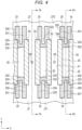
- the shape opened toward the extending direction outer side of the air chambers 32 and bending in the reverse C shape is illustrated as the shape of the cover members 23.
- the cover members 23 may include bending sections bending in, for example, a U shape or may be a shape opened toward the extending direction inner side of the air chambers 32.
- the connecting wall 232 is disposed further on the inner side than the end portions of the sidewalls 33 .
- the connecting wall 232 may be disposed further on the outer side than the end portions of the sidewalls 33.
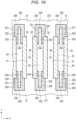
- the cover member 230 includes the pair of extending walls 231 and the connecting wall 232.
- the connecting wall 232 is disposed at the end portion on the outer side in the extending direction in the extending walls 231.
- the connecting wall 232 is located further on the outer side in an extending direction of the air chamber 32 than the end portions of the sidewalls 33.
- the cover member 230 is formed in a reverse C shape opened toward the inner side in the extending direction in a plan view.
- the pair of extending walls 231 includes the inner wall sections 234 formed on the inner surfaces of the sidewalls 33 and the outer wall sections 235.
- the void section 233 is formed between the pair of extending walls 231.
- the connecting wall 232 may be a flat wall member or may be a bent wall.
- a width dimension in the X direction of the void section 233 is fixed over the entire length in the extending direction.
- the inner wall sections 234 have a width dimension in an arranging direction thereof smaller than the thickness dimension of the outer wall sections 235 and is configured thinner than the outer wall sections 235.
- the pair of extending walls 231 is wall members extending in the extending direction of the subject air chamber 32.
- the pair of extending walls 231 includes the inner wall sections 234 formed on the inner surfaces of the pair of sidewalls configuring both the sides in the arranging direction of the air chambers 32 and the outer wall sections 235 disposed further on the outer side than end portions of the pair of sidewalls.
- the void section 233 is formed between the pair of extending walls 231. As an example, the void section 233 has fixed width in the extending direction.
- the inner wall sections 234 have a thickness dimension, which is a dimension in the arranging direction, smaller than the thickness dimension of the outer wall sections 235 and are configured thinner than the outer wall sections 235.
- the void section 233 is a slit-like space having a width dimension smaller than the width dimension of the air chamber 32 in the width direction.
- the void section 233 is formed between the end portions of the sidewall 33 on both the sides in the extending direction.
- the void section 233 opened toward the inner side is formed from a position beside the end portions of the sidewalls 33 to the connecting wall 232 provided further on the outer side than the end portions of the sidewalls 33.
- the void section 233 communicates with the air chamber 32.
- the void section 233 may function as the air chamber 32 as well.
- the connecting wall 232 is a wall-like member that closes the air chamber 32 in a position further on the outer side in the extending direction of the air chamber 32 than the end portions of the sidewalls 33.
- the connecting wall 232 is a wall member orthogonal to or crossing the extension of the air chamber 32.
- the connecting wall 232 connects the pair of extending walls 231 in the arranging direction and is formed from the counter surface of the nozzle plate 12 to the bottoms of the grooves in the Z direction to cover the end portion of the air chamber 32.
- the cover member 230 is made of a material having hardness lower than the hardness of a piezoelectric material.
- the cover member 230 is made of a resin material softer than the sidewalls 33.
- the cover member 230 is made of a photosensitive resin material.
- the cover member 230 is formed by exposing the photosensitive resin to light and hardening the photosensitive resin in the shape of the cover member 230. Peeling of the cover member 230 by contraction stress at the time of the hardening can be prevented because the void section 233 is interposed between the pair of extending walls 231 separated from each other in the X direction, which is a vibrating direction of the sidewalls 33.
- the cover member 230 since the cover member 230 includes the void section 233, it is possible to reduce contraction stress of the photosensitive resin if the cover member 230 is formed and prevent peeling of the cover member 230 by the contraction stress. Therefore, it is possible to ensure satisfactory ejection performance. If the sidewalls 33 are displaced in the X direction, since the extending walls 231 are elastically deformed to be displaced in the X direction, the cover member 230 can absorb displacement vibration of the sidewalls 33 and prevents vibration from being transmitted from one sidewall 33 to the other sidewall 33. That is, it is possible to prevent vibration of one sidewall 33 from being transmitted to the other sidewall 33 and it is possible to prevent so-called cross talk. It is easy to maintain the ejection performance.
- the connecting wall 232 may be provided in a halfway portion in the extending direction of the pair of extending walls 231 and may have a shape including the void sections 233 respectively on the inner side and the outer side in the extending direction.
- actuators 22 including the plurality of grooves are disposed in the principal plane portion of the substrate 21 .
- actuators may be provided on the end face of the substrate 21.
- the number of nozzle rows is not limited to the number in the embodiment. One row or three or more rows of nozzles may be provided.
- the actuator base 11 including the stacked piezoelectric body including the piezoelectric members on the substrate 21 is illustrated.
- the actuator base 11 may be formed by, for example, only the piezoelectric members without using a substrate.
- One piezoelectric member may be used rather than the two piezoelectric members.
- the supply side and the discharge side may be opposite or the supply side and the discharge side may be configured to be switchable.
- the circulation-type inkjet head is illustrated in which one side of the pressure chamber 31 is the supply side and the other side is the discharge side and the ink in the first common chamber flows in from one side of the pressure chamber 31 and flows out from the other side.
- the inkjet head may be a non-circulation type.
- a configuration may be adopted in which common chambers on both the sides of the pressure chamber 31 are the supply side and the ink flows in from both the sides. That is, a configuration may be adopted in which the ink flows in from both the sides of the pressure chamber 31 and flows out from the nozzles 28 disposed in the center of the pressure chamber 31.
- Shapes of the cover members 23 respectively formed at both the ends may be different from each other.
- the supply holes 25 provided in the substrate 21 are not limited to a shape of a plurality of circular holes provided between the pair of actuators 22 illustrated in FIG. 2 .
- the supply holes 25 may be one long hole provided between the pair of actuators 22.
- the liquid to be ejected is not limited to the ink for printing.
- the liquid may be, for example, liquid including conductive particles for forming a wiring pattern of a printed wiring board.
- the inkjet head is used for the liquid ejection device such as the inkjet printer.
- the inkjet head can also be used for, for example, a 3D printer, an industrial manufacturing machine, and a medical use.
- the inkjet head enables a reduction in size and weight and a reduction in cost.
Landscapes
- Particle Formation And Scattering Control In Inkjet Printers (AREA)
Abstract
Description
- Embodiments described herein relate generally to a liquid ejection head.
- In recent years, high productivity is requested for an inkjet head. An increase in speed and an increase in a liquid droplet amount are problems in the inkjet head. For example, a share-mode shared-wall inkjet head generally adopts so-called three-cycle driving for sharing the same driving element in two pressure chambers and simultaneously driving one third of a plurality of arrayed chambers as pressure chambers. An independent driving head is also developed that uses both sides of a pressure chamber to be driven as dummy pressure chambers and drives one pressure chamber with independent two driving elements. For example, a structure is also developed in which a large number of grooves are formed in a piezoelectric body, entrances of the grooves are closed by photosensitive resin walls or the like at every other grooves, and the grooves not closed in the entrances are used as pressure chambers and the closed grooves are used as air chambers to perform independent driving.
- In the inkjet head explained above, if walls for sealing the air chambers are formed using photosensitive resin, peeling is sometimes caused between the photosensitive resin and the driving elements, which are bonding surfaces, by contraction reaction of the photosensitive resin. If the formation of the walls of the air chambers is insufficient, ink intrudes into the air chambers, natural vibration periods of the pressure chambers adjacent to each other deviate and pressure chamber natural vibration frequency fluctuation in a plane increases, causing deterioration in ejection performance. If the air chambers are filled with the ink, a (crosstalk) phenomenon in which vibration is transmitted to the adjacent pressure chambers occurs. As a result, deterioration and omission of ink arrival accuracy occur, causing deterioration in ejection performance.
- Related art is described in, for example,
JP-A-2015-189031 - To this end, there is provided a liquid ejection head comprising a plurality of sidewalls forming a plurality of grooves that alternately configure a plurality of pressure chambers and a plurality of air chambers; and a cover member including an inner wall section formed between a pair of the sidewalls configuring both sides of each of the air chambers and an outer wall section disposed further on an outer side than end portions of the pair of sidewalls, the cover member including a void section in at least a part thereof and closing an opening end portion of the air chamber. Preferred embodiments are set out in dependent claims.
-
-
FIG. 1 is a perspective view illustrating an inkjet head according to an embodiment; -
FIG. 2 is an exploded perspective view illustrating a configuration of a part of the inkjet head; -
FIG. 3 is a perspective view in which a main part of the inkjet head illustrated inFIG. 2 is partially enlarged; -
FIG. 4 is a sectional view illustrating a configuration of the inkjet head in an enlarged form; -
FIG. 5 is a sectional view of the inkjet head illustrated inFIG. 4 taken along an F5-F5 line; -
FIG. 6 is a sectional view of the inkjet head illustrated inFIG. 4 taken along an F6-F6 line; -
FIG. 7 is a partially enlarged sectional view in which a part of a cross section of the inkjet head illustrated inFIG. 2 taken along an F7-F7 line is enlarged; -
FIG. 8 is a partially enlarged sectional view for explaining a driving operation of the inkjet head; -
FIG. 9 is a schematic diagram illustrating an inkjet printer according to the embodiment; and -
FIG. 10 is a sectional view illustrating a configuration of a part of an inkjet head according to another embodiment in an enlarged form. - An object of embodiments is to provide a liquid ejection head that can ensure a satisfactory ejection characteristic.
- A liquid ejection head according to an embodiment includes a plurality of sidewalls and a cover member. The plurality of sidewalls form a plurality of grooves that alternately configure a plurality of pressure chambers and a plurality of air chambers. The cover member includes an inner wall section formed between a pair of the sidewalls configuring both sides of each of the air chambers and an outer wall section disposed further on an outer side than end portions of the pair of sidewalls. The cover member includes a void section in at least a part thereof and closes an opening end portion of the air chamber.
- A configuration of an
inkjet head 10, which is a liquid ejection head, according to a first embodiment is explained below with reference toFIGS. 1 to 8 .FIG. 1 is a perspective view illustrating an inkjet head according to the first embodiment.FIG. 2 is an exploded perspective view of a part of the inkjet head.FIG. 3 is a perspective view illustrating a configuration of a part of the inkjet head in an enlarged form.FIGS. 4 to 7 are sectional views illustrating configurations of parts of the inkjet head in an enlarged form.FIG. 8 is an explanatory diagram of a driving state. X, Y, and Z in the figures respectively indicate a first direction, a second direction, and a third direction orthogonal to one another. Note that, in this embodiment, directions are explained based on a posture in which a parallel arrangement direction ofnozzles 28 andpressure chambers 31 of theinkjet head 10 extends along an X axis, an extending direction of thepressure chambers 31 is along a Y axis, and an ejecting direction of liquid is along a Z axis. However, the directions are not limited to these directions. - As illustrated in
FIGS. 1 to 7 , theinkjet head 10 is a share-mode shared-wall inkjet head of a so-called side shooter type. Theinkjet head 10 is a device for ejecting ink and is mounted, for example, on the inside of an inkjet printer. For example, theinkjet head 10 is an inkjet head of an independent driving type in which thepressure chambers 31 andair chambers 32 are alternately disposed. Theair chambers 32 are air chambers to which ink is not supplied and do not include thenozzles 28. - The
inkjet head 10 includes anactuator base 11, anozzle plate 12, and aframe 13. Theactuator base 11 is an example of a base material. Anink chamber 27 to which ink, which is an example of liquid, is supplied is formed on the inside of theinkjet head 10. - Further, the
inkjet head 10 includes components such as a circuit board 17 that controls theinkjet head 10 and amanifold 18 that forms a part of a path between theinkjet head 10 and an ink tank. - As illustrated in
FIG. 2 , theactuator base 11 includes asubstrate 21 and a pair ofactuators 22. - The
substrate 21 is formed in a rectangular plate shape by ceramics such as alumina. Thesubstrate 21 includes a flat mounting surface. The pair ofactuators 22 is bonded to the mounting surface of thesubstrate 21. A plurality ofsupply holes 25 and a plurality ofdischarge holes 26 are formed in thesubstrate 21. - As illustrated in
FIGS. 2 ,5, and 6 ,pattern wires 211 are formed on thesubstrate 21 of theactuator base 11. Thepattern wires 211 are formed by, for example, a nickel thin film. Thepattern wires 211 include a common pattern and an individual pattern and are configured in a predetermined pattern shape connected toelectrode layers 34 formed in theactuators 22. For example, thepattern wires 211 are formed in positions avoiding thesupply holes 25 and thedischarge holes 26. - The
supply holes 25 are provided side by side in the longitudinal direction of theactuators 22 between the pair ofactuators 22 in the center of thesubstrate 21. Thesupply holes 25 communicate with an ink supply section of themanifold 18. Thesupply holes 25 are connected to the ink tank via the ink supply section. Thesupply holes 25 supply the ink in the ink tank to theink chamber 27. - The
discharge holes 26 are provided side by side in two rows across thesupply holes 25 and the pair ofactuators 22. Thedischarge holes 26 communicate with an ink discharge section of themanifold 18. The discharge holes 26 are connected to the ink tank via the ink discharge section. The discharge holes 26 discharge the ink in theink chamber 27 to the ink tank. - The pair of
actuators 22 is bonded to the mounting surface of thesubstrate 21. The pair ofactuators 22 is provided on thesubstrate 21 side by side in two rows across the supply holes 25. Each of theactuators 22 is formed by plate-like two piezoelectric bodies formed by, for example, lead zirconate titanate (PZT). The two piezoelectric bodies are pasted together such that polarization directions thereof are directions opposite to each other with respect to the thickness direction thereof. Theactuators 22 are bonded to the mounting surface of thesubstrate 21 by, for example, an epoxy adhesive having a thermosetting property. As illustrated inFIG. 2 , theactuators 22 are disposed side by side in parallel in theink chamber 27 to correspond to thenozzles 28 disposed side by side in two rows. Theactuators 22 divide theink chamber 27 into a firstcommon chamber 271 in which the supply holes 25 are opened and two secondcommon chambers 272 in which the discharge holes 26 are opened. - The width in the latitudinal direction of the
actuator 22 gradually increases from the top side toward the substrate side. A sectional shape in a direction (the latitudinal direction) orthogonal to the longitudinal direction of theactuator 22 is formed in a trapezoidal shape. Aside surface section 221 of theactuator 22 includes inclined surfaces inclined with respect to the second direction and the third direction. The top of theactuator 22 is bonded to thenozzle plate 12. Theactuator 22 includes a plurality ofpressure chambers 31 and a plurality ofair chambers 32. Theactuator 22 includes a plurality ofsidewalls 33 functioning as driving elements and includes, among the plurality ofsidewalls 33, grooves configuring thepressure chambers 31 and theair chambers 32. In other words, thesidewalls 33 function as columnar driving elements formed among the grooves forming thepressure chambers 31 and theair chambers 32. -
FIG. 4 is a sectional view in which one of theactuators 22 of theinkjet head 10 illustrated inFIG. 2 is partially enlarged.FIG. 5 is a sectional view of the groove configuring thepressure chamber 31 of theinkjet head 10 illustrated inFIG. 4 taken along F5-F5.FIG. 6 is a sectional view of the groove configuring theair chamber 32 of theinkjet head 10 illustrated inFIG. 4 taken along F6-F6. - As illustrated in
FIGS. 2 ,5, and 6 , the bottom surface section of the groove and the principal plane of thesubstrate 21 are connected by theinclined sidewall sections 221. Thepressure chambers 31 and theair chambers 32 are alternately disposed. Thepressure chambers 31 and theair chambers 32 respectively extend in a direction crossing the longitudinal direction of theactuator 22. The plurality of thepressure chambers 31 and the plurality ofair chambers 32 are disposed in parallel in the first direction (the X axis in the figures), which is the longitudinal direction of theactuator 22. In this embodiment, for example, the width dimension in the X direction of the grooves is fixed in the depth direction extending in the Z direction. A cross section orthogonal to the Y direction, which is an extending direction of the grooves, is formed in a rectangular shape. - Note that a shape of the
pressure chambers 31 and a shape of theair chambers 32 may be different. Thesidewalls 33 are formed between thepressure chambers 31 and theair chambers 32 and deformed according to a driving signal to change the volume of thepressure chambers 31. - The electrode layers 34 are respectively provided on the inner wall surfaces of the
pressure chambers 31 and theair chambers 32 and theside surface section 221 of theactuator base 11. The electrode layers 34 are formed by a conductive film such as a nickel thin film. The electrode layers 34 lead from the inner surface sections of the grooves onto thesubstrate 21 through theside surface section 221 and are connected to thepattern wires 211. For example, the electrode layers 34 are formed on at least one of the side surface sections and the bottom surface sections of thesidewalls 33. - The plurality of
pressure chambers 31 communicate with the plurality ofnozzles 28 of thenozzle plate 12 bonded to the tops of thepressure chambers 31. Both ends in the second direction of each of thepressure chambers 31 communicate with theink chamber 27. That is, one end portion is opened to the firstcommon chamber 271 of theink chamber 27 and the other end portion is opened to the secondcommon chambers 272 of theink chamber 27. Therefore, ink flows in from one end portion of thepressure chamber 31 and flows out from the other end portion. The ink may flows in from both the end portions of thepressure chamber 31. - As illustrated in
FIGS. 3 and6 , one side in the third direction (the Z direction) of theair chamber 32 is closed by thenozzle plate 12 bonded to the top of theair chamber 32. For example, both the ends in the second direction of the plurality ofair chambers 32 are closed by thecover members 23. That is, thecover members 23 are respectively disposed between the firstcommon chamber 271 of theink chamber 27 and theair chamber 32 and between theair chamber 32 and the secondcommon chambers 272. Both ends of theair chamber 32 is separated from theink chamber 27. Therefore, theair chamber 32 configures an air chamber into which ink does not flow. - For example, the
cover members 23 are respectively provided at both the ends in the Y direction (the second direction), which is an extending direction of theair chambers 32. Thecover members 23 connect end portions of thesidewalls 33 and separate thecommon chambers air chamber 32. Thecover members 23 includevoid sections 233 at least in a part of thecover members 23 and close an opening end portion of theair chamber 32. - Each of the
cover members 23 includes a pair of extendingwalls 231 extending in the extending direction of theair chamber 32 and a connectingwall 232 that connects the pair of extendingwalls 231 and includes thevoid section 233 formed between the pair of extendingwalls 231. For example, thevoid section 233 smaller than the width between the pair ofsidewalls 33 is formed between the pair of extendingwalls 231. That is, the pair of extendingwalls 231 is separated in the first direction (the X direction), which is a deforming direction of the pair of extendingwalls 231. For example, thecover member 23 is formed in a reverse C shape or a U shape opened toward the outer side in the extending direction of theair chamber 32 in a plan view as illustrated inFIG. 4 . - The pair of extending
walls 231 is wall members extending in the extending direction and the depth direction of thesubject air chamber 32. The pair of extendingwalls 231 integrally includesinner wall sections 234 formed on the inner surfaces of a pair of sidewalls configuring both the sides in an arranging direction of theair chambers 32 andouter wall sections 235 disposed further on the outer side than end portions of the pair of sidewalls. For example, the pair of extendingwalls 231 is formed in a range from a counter surface of thenozzle plate 12 to the bottoms of the grooves over the entire length of the depth of the grooves in the Z direction (depth direction). Thevoid section 233 is formed between the pair of extendingwalls 231. As an example, a width dimension in the X direction of thevoid section 233 is fixed over the entire length in the extending direction. Theinner wall sections 234 have smaller thickness dimension in the arranging direction and are configured thinner than theouter wall sections 235 in the arranging direction. - The
void section 233 is a slit-like space having a width dimension smaller than the width dimension of theair chamber 32 in the width direction. Thevoid section 233 is formed between the end portions of thesidewalls 33 on both the sides in the extending direction (for example, thevoid section 233 may partially extend into theair chamber 32 between the sidewalls 33). Thevoid section 233 is formed over end portions of the pair of extendingwalls 231 from a position beside the end portions of the sidewalls 33 in a direction away from theair chamber 32 and the connecting wall 232 (for example, thevoid section 233 may partially extend outside theair chamber 32 between the sidewalls 33) . In this embodiment, thevoid section 233 opened toward the outer side is formed to the connectingwall 232 provided further on the inner side than the end portions of thesidewalls 33. - The connecting
wall 232 is a wall-like member that closes theair chamber 32 in a position further on the inner side in the extending direction of theair chamber 32 than the end portions of thesidewalls 33. The connectingwall 232 is a wall member extending along a surface orthogonal to the longitudinal direction of theair chamber 32. The connectingwall 232 connects the end portions on the inner side of the pair of extendingwalls 231 in the arranging direction and is formed from the counter surface of thenozzle plate 12 to the bottoms of the grooves in the Z direction to cover the end portion of theair chamber 32. - The
cover member 23 is made of a material having hardness lower than the hardness of a piezoelectric material. For example, thecover member 23 is made of a resin material softer than thesidewalls 33. As an example, thecover member 23 is made of a photosensitive resin material. For example, after photosensitive resin is applied to both end portions of theair chamber 32, thecover member 23 is formed by exposing the photosensitive resin to light and hardening the photosensitive resin in the shape of thecover member 23. Peeling of thecover member 23 by contraction stress at the time of the hardening can be prevented because thevoid section 233 is interposed between the pair of extendingwalls 231 separated from each other in the X direction, which is a vibrating direction of thesidewalls 33. - The
nozzle plate 12 is formed by, for example, a rectangular film made of polyimide. Thenozzle plate 12 faces the mounting surface of theactuator base 11. In thenozzle plate 12, a plurality ofnozzles 28 piercing through thenozzle plate 12 in the thickness direction thereof are formed. - The plurality of
nozzles 28 are provided as many as thepressure chambers 31 and are disposed to respectively face thepressure chambers 31. The plurality ofnozzles 28 are disposed in the first direction (the X direction) and arrayed in two rows to correspond to the pair ofactuators 22. Each of thenozzles 28 is formed in a tubular shape, the axis of which extends in the third direction. For example, even if the diameter of thenozzles 28 is fixed, thenozzles 28 may have a shape reduced in diameter toward the center or the distal end portion thereof. Thenozzles 28 are disposed to face halfway portions in the extending direction of thepressure chambers 31 formed in the pair ofactuators 22 and respectively communicate with thepressure chambers 31. Thenozzles 28 are disposed one by one in positions corresponding to the positions between both the end portions of thepressure chambers 31, for example, the longitudinal direction centers of thepressure chambers 31. - The
frame 13 is formed in a rectangular frame shape by, for example, a nickel alloy. Theframe 13 is interposed between the mounting surface of theactuator base 11 and thenozzle plate 12. Theframe 13 is bonded to the mounting surface of theactuator base 11 and thenozzle plate 12. That is, thenozzle plate 12 is attached to theactuator base 11 via theframe 13. - The manifold 18 is bonded to a side of the
actuator base 11 opposite to thenozzle plate 12. An ink supply section, which is a flow path communicating with the supply holes 25, and an ink discharge section, which is a flow path communicating with the discharge holes 26, are formed on the inside of the manifold 18. - The circuit board 17 illustrated in
FIG. 1 is a film carrier package (FCP). The circuit board 17 includes afilm 51 on which a plurality of wires are formed, thefilm 51 being made of flexible resin, and a drivingIC 52 connected to the plurality of wires of thefilm 51. The drivingIC 52 is electrically connected to the electrode layers 34 via the wires of thefilm 51 and thepattern wires 211. - On the inside of the
inkjet head 10 configured as explained above, theink chamber 27 surrounded by theactuator base 11, thenozzle plate 12, and theframe 13 is formed. That is, theink chamber 27 is formed between theactuator base 11 and thenozzle plate 12. For example, theink chamber 27 is partitioned into three sections in the second direction (the Y direction) by the twoactuators 22 and includes the two secondcommon chambers 272, which are common chambers in which the discharge holes 26 are opened, and the firstcommon chamber 271, which is a common chamber in which the supply holes 25 are opened. The firstcommon chamber 271 and the secondcommon chambers 272 communicate with the plurality ofpressure chambers 31. -
FIG. 7 is an enlarged sectional view of a portion where theinkjet head 10 illustrated inFIG. 2 is taken along F7-F7 in the longitudinal direction.FIG. 8 is a partially enlarged sectional view illustrating an example of a state in which thesidewalls 33 illustrated inFIG. 7 is subjected to share mode deformation. - In the
inkjet head 10 configured as explained above, ink circulates between the ink tank and theink chamber 27 through the supply holes 25, thepressure chambers 31, and the discharge holes 26. The drivingIC 52 applies a driving voltage to the electrode layers 34 of thepressure chambers 31 via the wires of thefilm 51 according to, for example, a signal input from a control unit of the inkjet printer to thereby cause a potential difference between the electrode layers 34 of thepressure chambers 31 and the electrode layers 34 of theair chambers 32 to selectively subject thesidewalls 33 to share mode deformation. The drivingIC 52 deforms the sidewalls 33 formed between thepressure chambers 31 and theair chambers 32 according to a driving signal to change the volume of thepressure chambers 31. - As indicated by a solid line in
FIG. 8 , thesidewalls 33 undergo the share mode deformation, whereby the volume of thepressure chambers 31 in which the electrode layers 34 are provided increases and the pressure in thepressure chambers 31 decreases. Consequently, the ink in theink chamber 27 flows into thepressure chambers 31. - In a state in which the volume of the
pressure chambers 31 increases, the drivingIC 52 applies a driving voltage having the opposite potential to the electrode layers 34 of thepressure chambers 31. Consequently, as indicated by an alternate long and two short dashes line inFIG. 8 , thesidewalls 33 undergo the share mode deformation, the volume of thepressure chambers 31 in which the electrode layers 34 are provided decreases, and the pressure in thepressure chambers 31 increases. Consequently, the ink in thepressure chambers 31 is pressurized and ejected from thenozzles 28. - A method of manufacturing the
inkjet head 10 is explained. First, a piezoelectric member, on which a plurality of grooves are formed, is stuck to the plate-like substrate 21 by an adhesive or the like, machining is applied to the piezoelectric member using a dicing saw, a slicer, or the like to mold theactuator base 11 having a predetermined external shape. Note that, for example, a block-like base member having thickness equivalent to a plurality ofactuator bases 11 may be formed and then divided to manufacture the plurality ofactuator bases 11 having a predetermined shape. - Subsequently, the electrode layers 34 and the
pattern wires 211 are formed on the inner surfaces of the grooves configuring thepressure chambers 31 and theair chambers 32 and the surface of thesubstrate 21. Consequently, the electrode layers 34 and thepattern wires 211 are respectively formed in predetermined parts on the surface of theactuator base 11. - Subsequently, both the ends of the
air chambers 32 are closed by forming thecover members 23 at the end portions of theair chambers 32. For example, photosensitive resin is filled in the grooves configuring theair chambers 32 and target parts are hardened by exposure to form thecover members 23. Alternatively, after the photosensitive resin is hardened, parts to be thevoid sections 233 are removed to form the slit-like void sections 233 and photosensitive resin layers are molded in a reverse C shape, whereby thecover members 23 are formed. - The
actuator base 11 is assembled to the manifold 18 and theframe 13 is stuck to one surface of thesubstrate 21 of theactuator base 11 by an adhesive sheet of thermoplastic resin. - Then, the assembled
frame 13, the tops of thesidewalls 33 of theactuators 22, and the surfaces of thecover members 23 on thenozzle plate 12 side are polished to be the same surface. Thenozzle plate 12 is bonded and attached to the polished surfaces of the tops of thesidewalls 33, theframe 13, and thecover members 23. At this time, thenozzles 28 are positioned to face thepressure chambers 31. Further, the drivingIC 52 and the circuit board 17 are connected to, via a flexible printed board, thepattern wires 211 formed on the principal plane of thesubstrate 21 as illustrated inFIG. 1 , whereby theinkjet head 10 is completed. - An example of an
inkjet printer 100 including theinkjet head 10 is explained below with reference toFIG. 9 . Theinkjet printer 100 includes ahousing 111, amedium supply unit 112, animage forming unit 113, amedium discharge unit 114, a conveyingdevice 115, and acontrol unit 116. - The
inkjet printer 100 is a liquid ejecting device that performs image formation processing on paper P by, for example, ejecting liquid such as ink while conveying the paper P as a recording medium, which is an ejection target object, along a predetermined conveying path A leading from themedium supply unit 112 to themedium discharge unit 114 through theimage forming unit 113. - The
housing 111 configures an outer frame of theinkjet printer 100. A discharge port for discharging the paper P to the outside is provided in a predetermined part of thehousing 111. - The
medium supply unit 112 includes a plurality of paper feeding cassettes and is configured to be capable of stacking and storing pluralities of pieces of the paper P of various sizes. - The
medium discharge unit 114 includes a paper discharge tray configured to be capable of holding the paper P discharged from the discharge port. - The
image forming unit 113 includes a supportingsection 117 that supports the paper P and a plurality ofhead units 130 disposed to face one another above the supportingsection 117. - The supporting
section 117 includes a conveying belt 118 provided in a loop shape in a predetermined region where image formation is performed, asupport plate 119 that supports the conveying belt 118 from the rear side thereof, and a plurality ofbelt rollers 120 provided on the rear side of the conveying belt 118. - The supporting
section 117 supports the paper P on a holding surface, which is the upper surface of the conveying belt 118, and feeds the conveying belt 118 at predetermined timing according to rotation of thebelt rollers 120 to thereby convey the paper P to a downstream side. - The
head units 130 include a plurality of inkjet heads 10 (for four colors),ink tanks 132 functioning as liquid tanks respectively mounted on the inkjet heads 10,connection flow paths 133 that connect the inkjet heads 10 and theink tanks 132, and circulation pumps 134, which are circulating units. Thehead units 130 are circulation-type head units that always circulate liquid in theink tanks 132 and thepressure chambers 31, theair chambers 32, and theink chambers 27 fabricated on the inside of theinkjet head 10. - In this embodiment, the
head units 130 include the inkjet heads 10 for four colors of cyan, magenta, yellow, and black and theink tanks 132 that respectively store inks of these colors. Theink tanks 132 are connected to the inkjet heads 10 by theconnection flow paths 133. Theconnection flow paths 133 includes supply flow paths connected to supply ports of the inkjet heads 10 and collection flow paths connected to discharge ports of the inkjet heads 10. - Not-illustrated negative pressure control devices such as pumps are coupled to the
ink tanks 132. The negative pressure control devices control the insides of theink tanks 132 to a negative pressure according to water head values of theinkjet head 10 and theink tanks 132 to form a meniscus having a predetermined shape with the inks supplied to thenozzles 28 of theinkjet head 10. - The circulation pumps 134 are, for example, liquid feeding pumps configured by piezoelectric pumps. The circulation pumps 134 are provided in the supply flow paths. The circulation pumps 134 are connected to a driving circuit of the
control unit 116 by wires and are configured to be controllable by a CPU (Central Processing Unit). The circulation pumps 134 circulate liquid in a circulation flow path including theinkjet head 10 and theink tanks 132. - The conveying
device 115 conveys the paper P along the conveying path A leading from themedium supply unit 112 to themedium discharge unit 114 through theimage forming unit 113. The conveyingdevice 115 includes a plurality of guide plate pairs 121 and a plurality of conveyingrollers 122 disposed along the conveying path A. - The plurality of guide plate pairs 121 respectively include pair of plate members disposed to face each other across the conveyed paper P and guide the paper P along the conveying path A.
- The conveying
rollers 122 are driven by the control of thecontrol unit 116 to rotate to send the paper P to the downstream side along the conveying path A. Note that sensors that detect conveyance states of the paper P are disposed in places of the conveying path A. - The
control unit 116 includes a control circuit such as a CPU, which is a controller, a ROM (Read Only Memory) that stores various programs and the like, a R_AM (Random Access Memory) that temporarily stores various variable data, image data, and the like, and an interface unit that receives data from the outside and outputs data to the outside. - In the
inkjet printer 100 configured as explained above, for example, if a printing instruction by operation of an operation input unit by a user is detected in the interface unit, thecontrol unit 116 drives the conveyingdevice 115 to convey the paper P and outputs a printing signal to thehead units 130 at predetermined timing to drive theinkjet head 10. As an ejecting operation, theinkjet head 10 sends a driving signal to the drivingIC 52 according to an image signal corresponding to image data, applies a driving voltage to the electrode layers 34 of thepressure chambers 31 via the wires to selectively drive thesidewalls 33 of theactuators 22 and eject the inks, which are droplets, from thenozzles 28, and forms an image on the paper P held on the conveying bels 118. As a liquid ejecting operation, thecontrol unit 116 drives the circulation pumps 134 to circulate liquid in the circulation flow path that passes through theink tanks 132 and theinkjet head 10. The circulation pumps 134 are driven by a circulating operation, whereby the inks in theink tanks 132 are supplied from the supply holes 25 to the firstcommon chamber 271 of theink chamber 27 through the ink supply section of the manifold 18. The inks are supplied to the plurality ofpressure chambers 31 of the pair ofactuators 22. The inks flow into the secondcommon chambers 272 of theink chamber 27 through thepressure chambers 31. The inks are discharged from the discharge holes 26 to theink tanks 132 through the ink discharge section of the manifold 18. - According to the embodiment explained above, since the
air chambers 32 are closed by thecover members 23 including thevoid sections 233, it is possible to reduce contraction stress at the time of the photosensitive resin hardening if thecover members 23 are formed. Therefore, it is possible to prevent the bonding surfaces of thecover members 23 from peeling from thesidewalls 33, prevent a material from being broken, and prevent inks from intruding into theair chambers 32. By preventing the inks from intruding into theair chambers 32, it is possible to prevent so-called crosstalk that affects the pressure of the inks in thepressure chambers 31 adjacent to each other. It is easy to maintain ejection performance. If thesidewalls 33 are displaced in the X direction, since the extendingwalls 231 are elastically deformed to be displaced in the X direction, thecover members 23 can absorb displacement vibration of thesidewalls 33 and prevent vibration from being transmitted from onesidewall 33 to theother sidewall 33. That is, it is possible to prevent vibration of onesidewall 33 from being transmitted to theother sidewall 33 and it is possible to prevent the so-called cross talk. It is easy to maintain the ejection performance. - Note that embodiments are not limited to the embodiment explained above per se. The constituent elements can be modified and embodied without departing from the gist of the embodiments in an implementation stage.
- For example, the shape opened toward the extending direction outer side of the
air chambers 32 and bending in the reverse C shape is illustrated as the shape of thecover members 23. However, not only this, but, for example, thecover members 23 may include bending sections bending in, for example, a U shape or may be a shape opened toward the extending direction inner side of theair chambers 32. - In the embodiment explained above, an example in which the connecting
wall 232 is disposed further on the inner side than the end portions of thesidewalls 33 is explained. However, not only this, but, for example, as another embodiment, as in acover member 230 illustrated inFIG. 10 , the connectingwall 232 may be disposed further on the outer side than the end portions of thesidewalls 33. - For example, the
cover member 230 includes the pair of extendingwalls 231 and the connectingwall 232. The connectingwall 232 is disposed at the end portion on the outer side in the extending direction in the extendingwalls 231. The connectingwall 232 is located further on the outer side in an extending direction of theair chamber 32 than the end portions of thesidewalls 33. As an example, thecover member 230 is formed in a reverse C shape opened toward the inner side in the extending direction in a plan view. The pair of extendingwalls 231 includes theinner wall sections 234 formed on the inner surfaces of thesidewalls 33 and theouter wall sections 235. Thevoid section 233 is formed between the pair of extendingwalls 231. For example, the connectingwall 232 may be a flat wall member or may be a bent wall. As an example, a width dimension in the X direction of thevoid section 233 is fixed over the entire length in the extending direction. Theinner wall sections 234 have a width dimension in an arranging direction thereof smaller than the thickness dimension of theouter wall sections 235 and is configured thinner than theouter wall sections 235. - The pair of extending
walls 231 is wall members extending in the extending direction of thesubject air chamber 32. The pair of extendingwalls 231 includes theinner wall sections 234 formed on the inner surfaces of the pair of sidewalls configuring both the sides in the arranging direction of theair chambers 32 and theouter wall sections 235 disposed further on the outer side than end portions of the pair of sidewalls. Thevoid section 233 is formed between the pair of extendingwalls 231. As an example, thevoid section 233 has fixed width in the extending direction. Theinner wall sections 234 have a thickness dimension, which is a dimension in the arranging direction, smaller than the thickness dimension of theouter wall sections 235 and are configured thinner than theouter wall sections 235. - The
void section 233 is a slit-like space having a width dimension smaller than the width dimension of theair chamber 32 in the width direction. Thevoid section 233 is formed between the end portions of thesidewall 33 on both the sides in the extending direction. In this embodiment, thevoid section 233 opened toward the inner side is formed from a position beside the end portions of thesidewalls 33 to the connectingwall 232 provided further on the outer side than the end portions of thesidewalls 33. In this embodiment, thevoid section 233 communicates with theair chamber 32. Thevoid section 233 may function as theair chamber 32 as well. - The connecting
wall 232 is a wall-like member that closes theair chamber 32 in a position further on the outer side in the extending direction of theair chamber 32 than the end portions of thesidewalls 33. The connectingwall 232 is a wall member orthogonal to or crossing the extension of theair chamber 32. The connectingwall 232 connects the pair of extendingwalls 231 in the arranging direction and is formed from the counter surface of thenozzle plate 12 to the bottoms of the grooves in the Z direction to cover the end portion of theair chamber 32. - The
cover member 230 is made of a material having hardness lower than the hardness of a piezoelectric material. For example, thecover member 230 is made of a resin material softer than thesidewalls 33. As an example, thecover member 230 is made of a photosensitive resin material. For example, after photosensitive resin is applied to both the end portions of theair chamber 32, thecover member 230 is formed by exposing the photosensitive resin to light and hardening the photosensitive resin in the shape of thecover member 230. Peeling of thecover member 230 by contraction stress at the time of the hardening can be prevented because thevoid section 233 is interposed between the pair of extendingwalls 231 separated from each other in the X direction, which is a vibrating direction of thesidewalls 33. - In this embodiment as well, since the
cover member 230 includes thevoid section 233, it is possible to reduce contraction stress of the photosensitive resin if thecover member 230 is formed and prevent peeling of thecover member 230 by the contraction stress. Therefore, it is possible to ensure satisfactory ejection performance. If thesidewalls 33 are displaced in the X direction, since the extendingwalls 231 are elastically deformed to be displaced in the X direction, thecover member 230 can absorb displacement vibration of thesidewalls 33 and prevents vibration from being transmitted from onesidewall 33 to theother sidewall 33. That is, it is possible to prevent vibration of onesidewall 33 from being transmitted to theother sidewall 33 and it is possible to prevent so-called cross talk. It is easy to maintain the ejection performance. - Note that the connecting
wall 232 may be provided in a halfway portion in the extending direction of the pair of extendingwalls 231 and may have a shape including thevoid sections 233 respectively on the inner side and the outer side in the extending direction. - In the embodiment explained above, an example in which the
actuators 22 including the plurality of grooves are disposed in the principal plane portion of thesubstrate 21 is explained. However, not only this, but, for example, actuators may be provided on the end face of thesubstrate 21. The number of nozzle rows is not limited to the number in the embodiment. One row or three or more rows of nozzles may be provided. - In the embodiment explained above, the
actuator base 11 including the stacked piezoelectric body including the piezoelectric members on thesubstrate 21 is illustrated. However, not only this, but theactuator base 11 may be formed by, for example, only the piezoelectric members without using a substrate. One piezoelectric member may be used rather than the two piezoelectric members. The supply side and the discharge side may be opposite or the supply side and the discharge side may be configured to be switchable. - In the embodiment explained above, as an example, the circulation-type inkjet head is illustrated in which one side of the
pressure chamber 31 is the supply side and the other side is the discharge side and the ink in the first common chamber flows in from one side of thepressure chamber 31 and flows out from the other side. However, not only this, but, for example, the inkjet head may be a non-circulation type. For example, a configuration may be adopted in which common chambers on both the sides of thepressure chamber 31 are the supply side and the ink flows in from both the sides. That is, a configuration may be adopted in which the ink flows in from both the sides of thepressure chamber 31 and flows out from thenozzles 28 disposed in the center of thepressure chamber 31. Shapes of thecover members 23 respectively formed at both the ends may be different from each other. The supply holes 25 provided in thesubstrate 21 are not limited to a shape of a plurality of circular holes provided between the pair ofactuators 22 illustrated inFIG. 2 . For example, the supply holes 25 may be one long hole provided between the pair ofactuators 22. - For example, the liquid to be ejected is not limited to the ink for printing. The liquid may be, for example, liquid including conductive particles for forming a wiring pattern of a printed wiring board.
- In the embodiment explained above, an example in which the inkjet head is used for the liquid ejection device such as the inkjet printer is explained. However, not only this, but the inkjet head can also be used for, for example, a 3D printer, an industrial manufacturing machine, and a medical use. The inkjet head enables a reduction in size and weight and a reduction in cost.
- According to at least one embodiment explained above, it is possible to provide a liquid ejection head and a method of manufacturing the liquid ejection head that can ensure a stable ejection characteristic.
- Besides, the several embodiments are explained above. However, these embodiments are presented as examples and are not intended to limit the scope of the invention. These new embodiments can be implemented in other various forms. Various omissions, substitutions, and changes can be made without departing from the gist of the invention. These embodiments and modifications thereof are included in the scope of the invention and included in the inventions described in the claims and the scope of the inventions.
Claims (13)
- A liquid ejection head comprising:a plurality of sidewalls (33) forming a plurality of grooves that alternately configure a plurality of pressure chambers (31) and a plurality of air chambers (32); anda cover member (23, 230) including an inner wall section formed between a pair of the sidewalls configuring both sides of each of the air chambers and an outer wall section disposed further on an outer side than end portions of the pair of sidewalls, the cover member including a void section (233) in at least a part thereof and closing an opening end portion of the air chamber.
- The head according to claim 1, wherein the void section is formed between the end portions of the pair of sidewalls configuring both the sides.
- The head according to claim 1 or 2, wherein the void section is a slit-like space having a width dimension smaller than the width dimension of the air chamber.
- The head according to any one of claim 1 to 3, whereinthe pressure chambers communicate with nozzles that ejects droplets, andthe cover member includes a pair of extending walls integrally including the inner wall section formed on an inner side surface of the air chamber between the pair of sidewalls and the outer wall section extending to an extending direction outer side of the air chamber from the inner wall section and a connecting wall connecting the pair of extending walls, and the void section smaller than width between the pair of sidewalls is formed between the pair of extending walls.
- The head according to claim 4, further comprising a nozzle plate, wherein
the pair of extending walls is formed in a range from a counter surface of the nozzle plate to the bottoms of the grooves over the entire length of the depth of the grooves in a depth direction. - The head according to any one of claims 1 to 5, wherein the inner wall sections have smaller thickness dimension in an arranging direction of the air chambers and are configured thinner than the outer wall sections in the arranging direction.
- The head according to any one of claims 1 to 6, whereinthe sidewalls are made of a piezoelectric material,the cover member is made of a photosensitive resin material having hardness lower than hardness of the piezoelectric material, andthe void section is opened toward an outer side in an extending direction of the air chamber.
- The head according to claim 7, wherein
the cover member is formed in a reverse C shape or a U shape, seen along an ejecting direction of liquid, opened toward the outer side in the extending direction of the air chamber. - The head according to any one of claims 1 to 6, whereinthe sidewalls are made of a piezoelectric material,the cover member is made of a photosensitive resin material having hardness lower than hardness of the piezoelectric material, andthe void section is opened toward an inner side in an extending direction of the air chamber.
- The head according to claim 9, wherein
the cover member is formed in a reverse C shape or a U shape, seen along an ejecting direction of liquid, opened toward the inner side in the extending direction of the air chamber. - The head according to claim 9 or 10, wherein the void section communicates with the air chamber.
- The head according to any one of claims 1 to 11, wherein the void section partially extends into the air chamber between the sidewalls and partially extends outside the air chamber between the sidewalls in an extending direction of the air chamber.
- The head according to any one of claims 1 to 12, wherein the connecting wall is provided in a halfway portion in the extending direction of the cover member, and have a shape including the void sections respectively on the inner side and the outer side in the extending direction.
Applications Claiming Priority (1)
| Application Number | Priority Date | Filing Date | Title |
|---|---|---|---|
| JP2023005348A JP2024101386A (en) | 2023-01-17 | 2023-01-17 | Liquid ejection head |
Publications (1)
| Publication Number | Publication Date |
|---|---|
| EP4403365A1 true EP4403365A1 (en) | 2024-07-24 |
Family
ID=88511177
Family Applications (1)
| Application Number | Title | Priority Date | Filing Date |
|---|---|---|---|
| EP23205643.2A Pending EP4403365A1 (en) | 2023-01-17 | 2023-10-24 | Liquid ejection head |
Country Status (3)
| Country | Link |
|---|---|
| EP (1) | EP4403365A1 (en) |
| JP (1) | JP2024101386A (en) |
| CN (1) | CN118358260A (en) |
Citations (2)
| Publication number | Priority date | Publication date | Assignee | Title |
|---|---|---|---|---|
| JP2015189031A (en) | 2014-03-27 | 2015-11-02 | 東芝テック株式会社 | Ink jet head, ink jet recording device, and manufacturing method of ink jet head |
| US20220176695A1 (en) * | 2020-12-07 | 2022-06-09 | Sii Printek Inc. | Head chip, liquid jet head, liquid jet recording device, and method of manufacturing head chip |
-
2023
- 2023-01-17 JP JP2023005348A patent/JP2024101386A/en active Pending
- 2023-10-12 CN CN202311325159.6A patent/CN118358260A/en active Pending
- 2023-10-24 EP EP23205643.2A patent/EP4403365A1/en active Pending
Patent Citations (2)
| Publication number | Priority date | Publication date | Assignee | Title |
|---|---|---|---|---|
| JP2015189031A (en) | 2014-03-27 | 2015-11-02 | 東芝テック株式会社 | Ink jet head, ink jet recording device, and manufacturing method of ink jet head |
| US20220176695A1 (en) * | 2020-12-07 | 2022-06-09 | Sii Printek Inc. | Head chip, liquid jet head, liquid jet recording device, and method of manufacturing head chip |
Also Published As
| Publication number | Publication date |
|---|---|
| CN118358260A (en) | 2024-07-19 |
| JP2024101386A (en) | 2024-07-29 |
Similar Documents
| Publication | Publication Date | Title |
|---|---|---|
| US12023925B2 (en) | Liquid ejection head | |
| JP2022149368A (en) | Liquid discharge head | |
| JP2023032351A (en) | Liquid discharge head and method for manufacturing liquid discharge head | |
| CN116552120B (en) | Liquid nozzle | |
| US11724500B2 (en) | Liquid ejection head | |
| US11845280B2 (en) | Liquid ejecting head and liquid ejecting device | |
| JP7681468B2 (en) | LIQUID DISCHARGE HEAD AND METHOD FOR MANUFACTURING LIQUID DISCHARGE HEAD | |
| JP2024063654A (en) | Liquid ejection head and liquid ejection device | |
| JP7689066B2 (en) | Liquid ejection head | |
| JP7634445B2 (en) | Liquid ejection head | |
| JP7681469B2 (en) | Liquid ejection head | |
| US12036794B2 (en) | Liquid ejection head | |
| JP7648479B2 (en) | LIQUID DISCHARGE HEAD AND METHOD FOR MANUFACTURING LIQUID DISCHARGE HEAD | |
| JP2024101386A (en) | Liquid ejection head | |
| JP7788294B2 (en) | Liquid ejection head and method of manufacturing the same | |
| EP4286165B1 (en) | Liquid ejection head | |
| JP7650783B2 (en) | LIQUID DISCHARGE HEAD AND METHOD FOR MANUFACTURING LIQUID DISCHARGE HEAD | |
| JP7657122B2 (en) | LIQUID DISCHARGE HEAD AND METHOD FOR MANUFACTURING LIQUID DISCHARGE HEAD | |
| JP7725345B2 (en) | Liquid ejection head and method of manufacturing the same | |
| US20250296331A1 (en) | Liquid ejection head and liquid ejection apparatus | |
| JP2023170460A (en) | liquid discharge head | |
| JP2025054604A (en) | LIQUID DISCHARGE HEAD AND METHOD FOR MANUFACTURING LIQUID DISCHARGE HEAD | |
| JP2024137288A (en) | Liquid ejection head and liquid ejection device | |
| JP2023046015A (en) | liquid ejection head | |
| JP2023173168A (en) | liquid discharge head |
Legal Events
| Date | Code | Title | Description |
|---|---|---|---|
| PUAI | Public reference made under article 153(3) epc to a published international application that has entered the european phase |
Free format text: ORIGINAL CODE: 0009012 |
|
| STAA | Information on the status of an ep patent application or granted ep patent |
Free format text: STATUS: THE APPLICATION HAS BEEN PUBLISHED |
|
| AK | Designated contracting states |
Kind code of ref document: A1 Designated state(s): AL AT BE BG CH CY CZ DE DK EE ES FI FR GB GR HR HU IE IS IT LI LT LU LV MC ME MK MT NL NO PL PT RO RS SE SI SK SM TR |
|
| RAP1 | Party data changed (applicant data changed or rights of an application transferred) |
Owner name: RISO TECHNOLOGIES CORPORATION |
|
| STAA | Information on the status of an ep patent application or granted ep patent |
Free format text: STATUS: REQUEST FOR EXAMINATION WAS MADE |
|
| P01 | Opt-out of the competence of the unified patent court (upc) registered |
Free format text: CASE NUMBER: APP_68074/2024 Effective date: 20241226 |
|
| 17P | Request for examination filed |
Effective date: 20250124 |