EP4403311A1 - Pneumatic tool motor including side cover with airflow-guiding structure - Google Patents
Pneumatic tool motor including side cover with airflow-guiding structure Download PDFInfo
- Publication number
- EP4403311A1 EP4403311A1 EP23215100.1A EP23215100A EP4403311A1 EP 4403311 A1 EP4403311 A1 EP 4403311A1 EP 23215100 A EP23215100 A EP 23215100A EP 4403311 A1 EP4403311 A1 EP 4403311A1
- Authority
- EP
- European Patent Office
- Prior art keywords
- gas accumulation
- grooves
- gas
- guiding
- air
- Prior art date
- Legal status (The legal status is an assumption and is not a legal conclusion. Google has not performed a legal analysis and makes no representation as to the accuracy of the status listed.)
- Granted
Links
Images



Classifications
-
- B—PERFORMING OPERATIONS; TRANSPORTING
- B25—HAND TOOLS; PORTABLE POWER-DRIVEN TOOLS; MANIPULATORS
- B25F—COMBINATION OR MULTI-PURPOSE TOOLS NOT OTHERWISE PROVIDED FOR; DETAILS OR COMPONENTS OF PORTABLE POWER-DRIVEN TOOLS NOT PARTICULARLY RELATED TO THE OPERATIONS PERFORMED AND NOT OTHERWISE PROVIDED FOR
- B25F5/00—Details or components of portable power-driven tools not particularly related to the operations performed and not otherwise provided for
-
- F—MECHANICAL ENGINEERING; LIGHTING; HEATING; WEAPONS; BLASTING
- F01—MACHINES OR ENGINES IN GENERAL; ENGINE PLANTS IN GENERAL; STEAM ENGINES
- F01C—ROTARY-PISTON OR OSCILLATING-PISTON MACHINES OR ENGINES
- F01C13/00—Adaptations of machines or engines for special use; Combinations of engines with devices driven thereby
- F01C13/02—Adaptations of machines or engines for special use; Combinations of engines with devices driven thereby for driving hand-held tools or the like
-
- F—MECHANICAL ENGINEERING; LIGHTING; HEATING; WEAPONS; BLASTING
- F01—MACHINES OR ENGINES IN GENERAL; ENGINE PLANTS IN GENERAL; STEAM ENGINES
- F01C—ROTARY-PISTON OR OSCILLATING-PISTON MACHINES OR ENGINES
- F01C21/00—Component parts, details or accessories not provided for in groups F01C1/00 - F01C20/00
- F01C21/18—Arrangements for admission or discharge of the working fluid, e.g. constructional features of the inlet or outlet
Definitions
- the present invention relates to a pneumatic tool motor including a side cover with an airflow-guiding structure and, more particularly, to an airflow-guiding structure for a side cover of a pneumatic tool motor cylinder, which reduces the wear caused by operation of the vanes of the rotor and increases the airtight effect through disposition of air accumulation grooves.
- U.S. Patent No. 3,472,323 ( ⁇ 323 patent) filed Oct. 24, 1967 also discloses an exhaust passage 12 in FIGS. 5 and 6 and teaches that the gas passing through the exhaust passage 121 flows out of a port 118 of a groove which widens outward at an outer side of the exhaust passage 121 and is then guided into the pneumatic tool body.
- the high pressure air can be filled through the exhaust passage 121 into the exhaust chamber 54 to rotate the rotor 50 received in the exhaust chamber 54. It can be seen that providing a gas groove which widens outward at the edge of the exhaust hole of the pneumatic tool cylinder body is a known design for increasing the air pressure operation.
- Swedish Patent No. SE 515533 C2 discloses four air inlets 32, 33, 35, and 36 in FIGS. 2 and 3 to permit operations in reverse directions, and gas grooves which widen outward are also provided at edges of the air inlets 32, 33, 35, and 36 to increase the inlet amount of air.
- FIG. 11 illustrates the inner housing 30 having a plurality of openings 31-34 which allow pressurized air to pass from the valve housing 12 into the ports 35-38.
- the first ports 35, 37 either alone or in combination, drive the rotor in a first direction when pressurized air is directed through the openings 31 and/or 33.
- the second ports 36, 38 drive the rotor in a second direction, either alone or in combination, when pressurized air is directed through the openings 32 and/or 34.
- the tool When two ports are receiving pressurized air, the tool will be in an overdrive state.
- the first and second ports 35-38 intercommunicate with inner grooves in the body of a side cover, such that pressurized air can be guided to drive the rotor to thereby generate a high-speed driving force.
- ⁇ 399 patent does not clearly illustrate enlarged guiding grooves extending from the inlet ports, the difference is merely a measure combining a conventional technique.
- U.S. Patent Publication No. 2004/0197218 A1 filed Mar. 8, 2004 discloses a pneumatic tool body in the form of a cylinder including air inlets 11 and back pressure air outlets 12, which are disposed at a side wall of the cylinder, and an air outlet 13 is formed on another side of the cylinder opposite to the air inlets 11 and the back pressure air outlets 12.
- the pressurized air within each air room C is expelled from the air outlet 13 when the rotor reaches to the air outlet 13.
- the back pressure air in each air room C is expelled from the back pressure air outlets 12.
- FIG. 1 shows a pneumatic motor with dual air intake disclosed in Taiwan Utility Model No. M541520 ('520 patent) which is a counterpart patent application of EP 3,351,723 B1 .
- the ⁇ 520 patent discloses a pneumatic cylinder 2 and a rotor 3.
- the pneumatic cylinder 2 includes a cylinder body 20 and an accommodating room 22 located in the cylinder body 20.
- the cylinder body 20 has two air inletting paths 24, two air venting paths 26, four air venting holes 28 and a front axial hole 29.
- the cylinder body 20 includes a middle pipe 40, a front cover 50 disposed on a front end 40a of the middle pipe 40, and a rear cover 60 disposed on a rear end 40b of the middle pipe 40.
- the front axial hole 29 is provided on the front cover 50.
- the four venting holes 28 are provided on the top and bottom sides of the middle pipe 40.
- the rear cover 60 has two air inlets 62 spaced from each other by 180 degrees, two air outlets 64 spaced from each other by 180 degrees, two rear air inletting grooves 66 provided on a front wall of the rear cover 60 and connected with the two air inlets 62 respectively, two rear air venting grooves 68 provided on the front wall of the rear cover 60 and connected with the two air outlets 64 respectively, and a rear axial hole 69.
- the middle pipe 40 is provided on the rear end 40b thereof with two rear air inletting recesses located correspondingly to the two air inlets 62 and communicating with the accommodating room 22, and two rear air venting recesses 44 located correspondingly to the two air outlets 64 and communicating with the accommodating room 22.
- the middle pipe 40 further has two air inletting channels 41 penetrating through the middle pipe 40 along an axis X of the cylinder 20 and connected with the two rear air inletting recesses 42 respectively, two air venting channels 43 penetrating through the middle pipe 40 along the axis X and connected with the two rear air venting recesses 42 respectively, two front air inletting recesses 46 provided on the front end 40a of the middle pipe 40 and connected with the two air inletting channels 41 respectively, and two front air venting recesses 48 provided on the front end 40a of the middle pipe 40 and connected with the two air venting channels 43 respectively.
- the two front air inletting recesses 46 and the two front air venting recesses 48 all communicate with the accommodating room 22.
- the front cover 50 has two front air inletting grooves 56 provided on a rear wall of the front cover 50 and communicating with the two air inletting channels 41 respectively, and two front air venting grooves 58 provided on the rear wall of the front cover 50 and communicating with the two air venting channels 43 respectively.
- Each of the air inletting paths 24 is composed of one of the air inlets 62, one of the rear air inletting grooves 66, one of the rear air inletting recesses 42, one of the air inletting channels 41, one of the front air inletting recesses 46, and one of the front air inletting grooves 56.
- Each of the air venting paths 26 is composed of one of the air outlets 64, one of the rear air venting grooves 68, one of the rear air venting recesses 44, one of the air venting channels 43, one of the front air venting recesses 48, and one of the front air venting grooves 58.
- the front cover 50 and the middle pipe 40 may be formed integrally.
- the air firstly passes through the two air inlets 62, and then divided into three parts.
- a first part of the air flows into the accommodating room 22 through the two rear air inletting recesses 42.
- a second part of the air enters the two rear air inletting grooves 66 and then flows into the accommodating room 22.
- a third part of the air passes through the two air inletting channels 41 and is divided into two parts.
- One part of the air flows into the accommodating room 22 through the two front air inletting recesses 46.
- the other part of the air enters the two front air inletting grooves 56 and then flows into the accommodating room 22.
- the air entering the accommodating room 22 blows the vanes 34 to move, causing the vanes 34 to move out from the grooves 32 and abut against the inner wall of the accommodating room 22.
- another portion of the air pushes the extended-out vanes 34 to move, thereby driving the rotor 3 to rotate in the accommodating room 22.
- the air leaves the accommodating room 22 through the two air venting paths 26.
- the air is partially vented through the air venting hole 28 in the first air venting process.
- a part of the air directly enters the rear air venting recess 44 and vented from the air outlet 64
- another part of the air enters the rear air venting groove 68 and vented from the air outlet 64
- the remaining part of the air enters the air venting channel 43 through the front air venting recess 48 and the front air venting groove 58 and then vented from the air outlet 64, so that the second air venting process is accomplished.
- the '520 patent has the following disadvantages.
- the vanes 34 move outward from the grooves 32 and abut against the inner wall of the accommodating room 22 at a high speed and a high pressure.
- the extended-out vanes 34 will pass through the two rear air inletting recesses 42 and two rear air venting recesses 44 and reach the notches formed in the inner wall of the accommodating room 22.
- the notches formed in the inner wall of the accommodating room 22 will cause abrasion of corners at the top edges of the vanes 34 under stress.
- the output of the rotor 3 is related to the airtight extent between the rotating vanes 34 and the inner wall of the accommodating room 22.
- the speed and the torque of the rotor will be reduced significantly, shortening the service life of the product.
- an objective of the present invention is to provide a pneumatic tool motor comprising: a cylinder including a chamber, two inlet passages, two discharge passages, and two exhaust holes; a rotor received in the chamber and including a plurality of channels receiving a plurality of vanes; a side cover disposed on a front end of the cylinder and configured for guiding airflow, with two front inlet guiding grooves provided on a rear wall of the side cover and respectively intercommunicating with the two inlet passages, with two front discharge guiding grooves provided on the rear wall of the side cover and respectively intercommunicating with the two discharge passages; and a rear cover disposed on a rear end of the cylinder, with the rear cover including two inlet ports and two exhaust ports, with two rear input guiding grooves provided on a front wall of the rear cover and respectively intercommunicating with the two inlet passages, with two rear output guiding grooves provided on the front wall of the rear cover and respectively intercommunicating with the two discharge
- the side cover includes two first gas accumulation grooves associated with the two front inlet guiding grooves respectively and aligned with the two discharge passages.
- Each of the two first gas accumulation grooves includes a gas accumulation portion aligned with an associated discharge passage and a gas guiding portion which intercommunicates with an associated front inlet guiding groove and which is shallower than the gas accumulation portion of the first gas accumulation groove.
- the side cover further includes two second gas accumulation grooves associated with the two front discharge guiding grooves respectively and aligned with the two inlet passages respectively.
- Each of the two second gas accumulation grooves includes a gas accumulation portion aligned with an associated inlet passage and a gas guiding portion which intercommunicates with an associated front discharge guiding groove and which is shallower than the gas accumulation portion of the second gas accumulation groove.
- Each of the two exhaust ports includes a gas accumulation portion aligned with an associated discharge passage and a gas guiding portion which intercommunicates with an associated rear output guiding groove and which is shallower than the gas accumulation portion of the exhaust port.
- Each of the two inlet ports includes a gas accumulation portion aligned with an associated inlet passage and a gas guiding portion which intercommunicates with an associated rear input guiding groove and which is shallower than the gas accumulation portion of the inlet port.
- each of the two first gas accumulation grooves has an area greater than an associated discharge passage.
- Each of the two second gas accumulation grooves has an area greater than an associated inlet passage.
- the gas guiding portion of each of the two first gas accumulation grooves is within an extent of an associated gas accumulation groove.
- the gas guiding portion of each of the two second gas accumulation grooves is within an extent of an associated gas accumulation groove.
- Each gas guiding portion of the rear cover is within an extent of an associated gas accumulation groove.
- a pneumatic tool motor comprises a cylinder 20 having a chamber 20, four exhaust ports 28, and a middle tube 40.
- a side cover 10 for guiding airflow is disposed on a front end of the middle tube 40.
- a rear cover 60 is disposed on a rear end of the middle tube 40.
- Two of the four exhaust ports 28 are disposed on a side of the middle tube 40, and another two exhaust ports 28 are disposed on another side of the middle tube 40 opposite to the side of the middle tube 40 and aligned with the two of the four exhaust ports 28 respectively.
- the rear cover 60 includes two diametrically disposed inlet ports 62 and two diametrically disposed outlet ports 64.
- the rear cover 60 further includes a front side having two rear input guiding grooves 66 intercommunicating with the two inlet ports 62 respectively.
- the front side of the rear cover 60 further includes two rear output guiding grooves 68 intercommunicating with the two exhaust ports 64 respectively.
- the rear end of the middle tube 40 intercommunicates with the chamber 22.
- the middle tube 40 further includes two diametrically disposed inlet passages 41 each extending through the middle tube 40 along an axis parallel to a central axis X of the middle tube 40.
- the two inlet passages 41 intercommunicate with the two exhaust ports 64 respectively.
- the middle tube 40 further includes two diametrically disposed discharge passages 43 each extending through the middle tube 40 along an axis parallel to the central axis X of the middle tube 40.
- the two discharge passages 43 intercommunicate with the two inlet ports 62 respectively.
- the side cover 10 includes two front inlet guiding grooves 16 disposed on a side wall of the side cover 10 and respectively intercommunicating with the two inlet passages 41 of the middle tube 40.
- the side wall of the side cover 10 further includes two front discharge guiding grooves 18 respectively intercommunicating with the two discharge passages 43 of the middle tube 40.
- the pneumatic tool motor includes two inlet passageways and two discharge passageways.
- Each of the two inlet passageways is comprised of one of the inlet ports 62, one of the two rear input guiding grooves 66, one of the two inlet passages 41, and one of the front inlet guiding grooves 16.
- Each of the two discharge passageways is comprised of one of the two exhaust ports 64, one of the two rear output guiding grooves 68, one of the two discharge passages 43, and one of the front discharge guiding grooves 18.
- the side cover 10 includes two first gas accumulation grooves 12 associated with the two front inlet guiding grooves 16 respectively and aligned with the two discharge passages 43 of the middle tube 40 respectively.
- Each of the two first gas accumulation grooves 12 has an area covering an associated discharge passage 43 of the middle tube 40.
- Each of the two first gas accumulation grooves 12 includes a gas accumulation portion 121 aligned with the associated discharge passage 43 of the middle tube 40 and a gas guiding portion 122 which intercommunicates with an associated front inlet guiding groove 16 and which is shallower than the gas accumulation portion 121 of the first gas accumulation groove 12.
- the side cover 10 includes two second gas accumulation grooves 14 associated with the two front discharge guiding grooves 18 respectively and aligned with the two inlet passages 41 of the middle tube 40 respectively.
- Each of the two second gas accumulation grooves 14 has an area covering an associated inlet passage 41 of the middle tube 40.
- Each of the two second gas accumulation grooves 14 includes a gas accumulation portion 141 aligned with the associated inlet passage 41 of the middle tube 40 and a gas guiding portion 14 2 which intercommunicates with an associated front discharge guiding groove 18 and which is shallower than the gas accumulation portion 141 of the second gas accumulation groove 14.
- Each of the two exhaust ports 64 is aligned with an associated discharge passage 43 of the middle tube 40 and has an area covering the associated discharge passage 43.
- Each of the two exhaust ports 64 includes a gas accumulation portion 641 aligned with the associated discharge passage 43 of the middle tube 40 and a gas guiding portion 642 which intercommunicates with an associated rear output guiding groove 68 and which is shallower than the gas accumulation portion 641 of the exhaust port 64.
- Each of the two inlet ports 62 is aligned with an associated inlet passage 41 of the middle tube 40 and has an area covering the associated inlet passage 41.
- Each of the two inlet ports 62 includes a gas accumulation portion 621 aligned with the associated inlet passage 41 of the middle tube 40 and a gas guiding portion 622 which intercommunicates with an associated rear input guiding groove 66 and which is shallower than the gas accumulation portion 621 of the inlet port 62.
- each gas guiding portion 122, 142, 622, 642 is within the extent of an associated gas accumulation groove 121, 141, 621, 641.
- the rotor 3 is rotatably received in the chamber 22 of the cylinder 2 and includes a plurality of channels 32 receiving a plurality of vanes 34 respectively.
- a front axle 36 extends forward from the rotor 3 and extends beyond the cylinder 2 to abut against the front cover 50.
- a rear axle 38 extends outward from the rotor 3 and extends beyond the cylinder 2 to abut against the rear cover 60.
- first and second gas accumulation grooves 12, 14 on the side cover 10 and the gas accumulation portions 621, 641 on the rear cover 60 high pressure air currents can be filled into the chamber 22 via the gas accumulation portions 122, 142, 621, 641 to actuate the vanes 34 of the rotor 3. Furthermore, a portion of the air currents is guided by the gas guiding portions 122, 142, 622, 642 into a central portion of the chamber 22 to generate back pressure acceleration for outward movement of the vanes 34 to abut against the inner wall of the chamber 22, thereby enhancing the airtightness.
- the chamber 22 is free of notches contacting with the vanes 34. This reduces rotational loss of the rotor 34 and maintains excellent airtightness, which is more durable and provides enhanced effect.
Landscapes
- Engineering & Computer Science (AREA)
- Mechanical Engineering (AREA)
- General Engineering & Computer Science (AREA)
- Actuator (AREA)
- Sawing (AREA)
Abstract
Description
- The present invention relates to a pneumatic tool motor including a side cover with an airflow-guiding structure and, more particularly, to an airflow-guiding structure for a side cover of a pneumatic tool motor cylinder, which reduces the wear caused by operation of the vanes of the rotor and increases the airtight effect through disposition of air accumulation grooves.
- In operation of a pneumatic tool motor, high pressure air is introduced into a pneumatic tool body and passes through air guiding holes to drive vanes of a rotor in the pneumatic tool body, thereby generating a rotational power transmitted to a driving end of the pneumatic tool for driving a tool. With continuous developments of the products, designers try to obtain the maximum force for driving the rotor at a fixed input air pressure. Namely, the vanes of the rotor can withstand the maximum air pressure by providing a better air supply condition for the introduced high pressure air, thereby enhancing the output power of the rotor. This is the major issue in the design of pneumatic tool motors for a long time, and the design pattern of increasing the rotor output power by increasing the air input can be analyzed through analysis of historic patent applications for pneumatic tool motors.
- After introducing the high pressure air into the pneumatic tool body, the high pressure air is filled through air guiding holes into a cylinder chamber receiving the rotor. However, in a case that the diameters of the outlets of the air guiding holes are not changed, it is difficult to instantly fill a large amount of high pressure air into the cylinder chamber to drive the vanes for high-torque rotation. To this end,
U.S. Patent No. 2,424, 638 (`638 patent) filed Nov. 8, 1994 discloses secondary ports 48 which are radially outside of the through-ports 52 and in the form of grooves with larger volumes. The `638 patent clearly discloses the air current from the through-ports 52 flows out of the secondary ports 48 and into the pneumatic tool body. Thus, high pressure air is guided by the through-ports 52 and is filled into the cylinder chamber for driving the rotor received in the cylinder chamber. Although the `638 patent does not clearly teach the operation of the secondary ports 48, a person skilled in the art may easily understand its purposes of generating a higher air pressure through filling a larger airflow into the secondary ports 48. -
U.S. Patent No. 3,472,323 (`323 patent) filed Oct. 24, 1967 also discloses anexhaust passage 12 inFIGS. 5 and6 and teaches that the gas passing through theexhaust passage 121 flows out of a port 118 of a groove which widens outward at an outer side of theexhaust passage 121 and is then guided into the pneumatic tool body. Thus, the high pressure air can be filled through theexhaust passage 121 into the exhaust chamber 54 to rotate therotor 50 received in the exhaust chamber 54. It can be seen that providing a gas groove which widens outward at the edge of the exhaust hole of the pneumatic tool cylinder body is a known design for increasing the air pressure operation. - Furthermore, Swedish Patent No.
SE 515533 C2 air inlets FIGS. 2 and3 to permit operations in reverse directions, and gas grooves which widen outward are also provided at edges of theair inlets -
U.S. Patent No. 6,250,399 B1 ('399 patent) filed Sep. 13, 1999 discloses two first ports 35, 37 and twosecond ports 36, 38 (FIG. 9) to permit operations in reverse directions. FIG. 11 illustrates theinner housing 30 having a plurality of openings 31-34 which allow pressurized air to pass from thevalve housing 12 into the ports 35-38. The first ports 35, 37, either alone or in combination, drive the rotor in a first direction when pressurized air is directed through the openings 31 and/or 33. Similarly, thesecond ports openings 32 and/or 34. When two ports are receiving pressurized air, the tool will be in an overdrive state. Namely, in `399 patent, the first and second ports 35-38 intercommunicate with inner grooves in the body of a side cover, such that pressurized air can be guided to drive the rotor to thereby generate a high-speed driving force. Although `399 patent does not clearly illustrate enlarged guiding grooves extending from the inlet ports, the difference is merely a measure combining a conventional technique. -
U.S. Patent Publication No. 2004/0197218 A1 (`218 application) filed Mar. 8, 2004 discloses a pneumatic tool body in the form of a cylinder including air inlets 11 and backpressure air outlets 12, which are disposed at a side wall of the cylinder, and an air outlet 13 is formed on another side of the cylinder opposite to the air inlets 11 and the backpressure air outlets 12. When the rotor 2 spins a half cycle in the clockwise direction, the pressurized air within each air room C is expelled from the air outlet 13 when the rotor reaches to the air outlet 13. When the rotor 2 spins to a full cycle, the back pressure air in each air room C is expelled from the backpressure air outlets 12. When the rotor 2 spins in the counterclockwise direction, the pressurized air is sucked in via the backpressure air outlets 12 and is expelled via the air outlet 13 and the air inlets 11 subsequently. As can be seen from the figures of `218 application, gas grooves which widen outward are disposed on outer edges of the air inlets 11 and the backpressure air outlets 12 to increase the inlet amount of air. Thus, `218 application can be deemed as a derivative design of the conventional technique. -
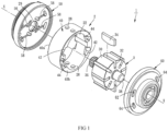
FIG. 1 shows a pneumatic motor with dual air intake disclosed inTaiwan Utility Model No. M541520 EP 3,351,723 B1 . The `520 patent discloses a pneumatic cylinder 2 and arotor 3. The pneumatic cylinder 2 includes a cylinder body 20 and anaccommodating room 22 located in the cylinder body 20. The cylinder body 20 has two air inletting paths 24, two air venting paths 26, fourair venting holes 28 and a frontaxial hole 29. The cylinder body 20 includes amiddle pipe 40, afront cover 50 disposed on afront end 40a of themiddle pipe 40, and arear cover 60 disposed on arear end 40b of themiddle pipe 40. The frontaxial hole 29 is provided on thefront cover 50. The fourventing holes 28 are provided on the top and bottom sides of themiddle pipe 40. Therear cover 60 has twoair inlets 62 spaced from each other by 180 degrees, twoair outlets 64 spaced from each other by 180 degrees, two rear air inlettinggrooves 66 provided on a front wall of therear cover 60 and connected with the twoair inlets 62 respectively, two rearair venting grooves 68 provided on the front wall of therear cover 60 and connected with the twoair outlets 64 respectively, and a rear axial hole 69. - The
middle pipe 40 is provided on therear end 40b thereof with two rear air inletting recesses located correspondingly to the twoair inlets 62 and communicating with theaccommodating room 22, and two rearair venting recesses 44 located correspondingly to the twoair outlets 64 and communicating with theaccommodating room 22. Themiddle pipe 40 further has two air inlettingchannels 41 penetrating through themiddle pipe 40 along an axis X of the cylinder 20 and connected with the two rear air inlettingrecesses 42 respectively, twoair venting channels 43 penetrating through themiddle pipe 40 along the axis X and connected with the two rearair venting recesses 42 respectively, two front air inletting recesses 46 provided on thefront end 40a of themiddle pipe 40 and connected with the twoair inletting channels 41 respectively, and two front air venting recesses 48 provided on thefront end 40a of themiddle pipe 40 and connected with the twoair venting channels 43 respectively. The two front air inletting recesses 46 and the two front air venting recesses 48 all communicate with theaccommodating room 22. - The
front cover 50 has two front air inlettinggrooves 56 provided on a rear wall of thefront cover 50 and communicating with the two air inlettingchannels 41 respectively, and two frontair venting grooves 58 provided on the rear wall of thefront cover 50 and communicating with the twoair venting channels 43 respectively. Each of the air inletting paths 24 is composed of one of theair inlets 62, one of the rear air inlettinggrooves 66, one of the rear air inlettingrecesses 42, one of the air inlettingchannels 41, one of the front air inletting recesses 46, and one of the front air inlettinggrooves 56. Each of the air venting paths 26 is composed of one of theair outlets 64, one of the rearair venting grooves 68, one of the rearair venting recesses 44, one of theair venting channels 43, one of the front air venting recesses 48, and one of the frontair venting grooves 58. In other potential embodiments, thefront cover 50 and themiddle pipe 40 may be formed integrally. - The air firstly passes through the two
air inlets 62, and then divided into three parts. A first part of the air flows into theaccommodating room 22 through the two rear air inlettingrecesses 42. A second part of the air enters the two rear air inlettinggrooves 66 and then flows into theaccommodating room 22. A third part of the air passes through the two air inlettingchannels 41 and is divided into two parts. One part of the air flows into theaccommodating room 22 through the two front air inletting recesses 46. The other part of the air enters the two front air inlettinggrooves 56 and then flows into theaccommodating room 22. The air entering theaccommodating room 22 blows thevanes 34 to move, causing thevanes 34 to move out from thegrooves 32 and abut against the inner wall of theaccommodating room 22. At this time, another portion of the air pushes the extended-outvanes 34 to move, thereby driving therotor 3 to rotate in theaccommodating room 22. - The following is the detailed process that the air leaves the
accommodating room 22 through the two air venting paths 26. Firstly, the air is partially vented through theair venting hole 28 in the first air venting process. Then, a part of the air directly enters the rear air venting recess 44 and vented from theair outlet 64, another part of the air enters the rearair venting groove 68 and vented from theair outlet 64, and the remaining part of the air enters theair venting channel 43 through the front air venting recess 48 and the frontair venting groove 58 and then vented from theair outlet 64, so that the second air venting process is accomplished. - However, the '520 patent has the following disadvantages. When the
rotor 3 rotates in theaccommodating room 22 at a high speed and a high torque, thevanes 34 move outward from thegrooves 32 and abut against the inner wall of theaccommodating room 22 at a high speed and a high pressure. At this time, the extended-outvanes 34 will pass through the two rear air inlettingrecesses 42 and two rearair venting recesses 44 and reach the notches formed in the inner wall of theaccommodating room 22. After long-term operation, the notches formed in the inner wall of theaccommodating room 22 will cause abrasion of corners at the top edges of thevanes 34 under stress. The output of therotor 3 is related to the airtight extent between the rotatingvanes 34 and the inner wall of theaccommodating room 22. The higher the airtightness, the better the driving efficiency of the pressurized air. When the airtightness is reduced, the speed and the torque of the rotor will be reduced significantly, shortening the service life of the product. - Thus, a need exists for a novel pneumatic tool motor which mitigates and/or obviates the above drawbacks.
- To solve the disadvantages of the prior art, an objective of the present invention is to provide a pneumatic tool motor comprising: a cylinder including a chamber, two inlet passages, two discharge passages, and two exhaust holes; a rotor received in the chamber and including a plurality of channels receiving a plurality of vanes; a side cover disposed on a front end of the cylinder and configured for guiding airflow, with two front inlet guiding grooves provided on a rear wall of the side cover and respectively intercommunicating with the two inlet passages, with two front discharge guiding grooves provided on the rear wall of the side cover and respectively intercommunicating with the two discharge passages; and a rear cover disposed on a rear end of the cylinder, with the rear cover including two inlet ports and two exhaust ports, with two rear input guiding grooves provided on a front wall of the rear cover and respectively intercommunicating with the two inlet passages, with two rear output guiding grooves provided on the front wall of the rear cover and respectively intercommunicating with the two discharge passages.
- The side cover includes two first gas accumulation grooves associated with the two front inlet guiding grooves respectively and aligned with the two discharge passages. Each of the two first gas accumulation grooves includes a gas accumulation portion aligned with an associated discharge passage and a gas guiding portion which intercommunicates with an associated front inlet guiding groove and which is shallower than the gas accumulation portion of the first gas accumulation groove.
- The side cover further includes two second gas accumulation grooves associated with the two front discharge guiding grooves respectively and aligned with the two inlet passages respectively. Each of the two second gas accumulation grooves includes a gas accumulation portion aligned with an associated inlet passage and a gas guiding portion which intercommunicates with an associated front discharge guiding groove and which is shallower than the gas accumulation portion of the second gas accumulation groove.
- Each of the two exhaust ports includes a gas accumulation portion aligned with an associated discharge passage and a gas guiding portion which intercommunicates with an associated rear output guiding groove and which is shallower than the gas accumulation portion of the exhaust port.
- Each of the two inlet ports includes a gas accumulation portion aligned with an associated inlet passage and a gas guiding portion which intercommunicates with an associated rear input guiding groove and which is shallower than the gas accumulation portion of the inlet port.
- In an example, each of the two first gas accumulation grooves) has an area greater than an associated discharge passage. Each of the two second gas accumulation grooves has an area greater than an associated inlet passage. The gas guiding portion of each of the two first gas accumulation grooves is within an extent of an associated gas accumulation groove. The gas guiding portion of each of the two second gas accumulation grooves is within an extent of an associated gas accumulation groove. Each gas guiding portion of the rear cover is within an extent of an associated gas accumulation groove.
- The present invention will become clearer in light of the following detailed description of illustrative embodiments of this invention described in connection with the drawings.
-
-
FIG. 1 is an exploded, perspective view corresponding toFIG. 2 ofTaiwan Utility Model No. M541520 -
FIG. 2 is a partial, exploded, perspective view of a pneumatic tool motor of a preferred embodiment according to the present invention. -
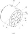
FIG. 3 is a perspective view of the pneumatic tool motor ofFIG. 2 after assembly. -
FIG. 4 is a perspective view of an airflow-guiding side cover ofFIG. 2 . -
FIG. 5 is a plan view of the airflow-guiding side cover ofFIG. 4 . -
FIG. 6 is another exploded, perspective view of the pneumatic tool motor ofFIG. 2 . -
FIG. 7 is a plan view of a rear cover of the pneumatic tool motor ofFIG. 6 . - With reference to
FIGS. 2 ,3 , and6 , a pneumatic tool motor according to the present invention comprises a cylinder 20 having a chamber 20, fourexhaust ports 28, and amiddle tube 40. Aside cover 10 for guiding airflow is disposed on a front end of themiddle tube 40. Arear cover 60 is disposed on a rear end of themiddle tube 40. Two of the fourexhaust ports 28 are disposed on a side of themiddle tube 40, and another twoexhaust ports 28 are disposed on another side of themiddle tube 40 opposite to the side of themiddle tube 40 and aligned with the two of the fourexhaust ports 28 respectively. Therear cover 60 includes two diametricallydisposed inlet ports 62 and two diametricallydisposed outlet ports 64. With reference toFIGS. 6 and7 , therear cover 60 further includes a front side having two rearinput guiding grooves 66 intercommunicating with the twoinlet ports 62 respectively. The front side of therear cover 60 further includes two rearoutput guiding grooves 68 intercommunicating with the twoexhaust ports 64 respectively. The rear end of themiddle tube 40 intercommunicates with thechamber 22. Themiddle tube 40 further includes two diametricallydisposed inlet passages 41 each extending through themiddle tube 40 along an axis parallel to a central axis X of themiddle tube 40. The twoinlet passages 41 intercommunicate with the twoexhaust ports 64 respectively. Themiddle tube 40 further includes two diametrically disposeddischarge passages 43 each extending through themiddle tube 40 along an axis parallel to the central axis X of themiddle tube 40. The twodischarge passages 43 intercommunicate with the twoinlet ports 62 respectively. - With reference to
FIGS. 4-7 , theside cover 10 includes two frontinlet guiding grooves 16 disposed on a side wall of theside cover 10 and respectively intercommunicating with the twoinlet passages 41 of themiddle tube 40. The side wall of theside cover 10 further includes two frontdischarge guiding grooves 18 respectively intercommunicating with the twodischarge passages 43 of themiddle tube 40. - Thus, the pneumatic tool motor includes two inlet passageways and two discharge passageways. Each of the two inlet passageways is comprised of one of the
inlet ports 62, one of the two rearinput guiding grooves 66, one of the twoinlet passages 41, and one of the frontinlet guiding grooves 16. Each of the two discharge passageways is comprised of one of the twoexhaust ports 64, one of the two rearoutput guiding grooves 68, one of the twodischarge passages 43, and one of the frontdischarge guiding grooves 18. - The side cover 10 includes two first
gas accumulation grooves 12 associated with the two frontinlet guiding grooves 16 respectively and aligned with the twodischarge passages 43 of themiddle tube 40 respectively. Each of the two firstgas accumulation grooves 12 has an area covering an associateddischarge passage 43 of themiddle tube 40. Each of the two firstgas accumulation grooves 12 includes agas accumulation portion 121 aligned with the associateddischarge passage 43 of themiddle tube 40 and agas guiding portion 122 which intercommunicates with an associated frontinlet guiding groove 16 and which is shallower than thegas accumulation portion 121 of the firstgas accumulation groove 12. - Furthermore, the
side cover 10 includes two secondgas accumulation grooves 14 associated with the two frontdischarge guiding grooves 18 respectively and aligned with the twoinlet passages 41 of themiddle tube 40 respectively. Each of the two secondgas accumulation grooves 14 has an area covering an associatedinlet passage 41 of themiddle tube 40. Each of the two secondgas accumulation grooves 14 includes agas accumulation portion 141 aligned with the associatedinlet passage 41 of themiddle tube 40 and agas guiding portion 14 2 which intercommunicates with an associated frontdischarge guiding groove 18 and which is shallower than thegas accumulation portion 141 of the secondgas accumulation groove 14. - Each of the two
exhaust ports 64 is aligned with an associateddischarge passage 43 of themiddle tube 40 and has an area covering the associateddischarge passage 43. Each of the twoexhaust ports 64 includes agas accumulation portion 641 aligned with the associateddischarge passage 43 of themiddle tube 40 and agas guiding portion 642 which intercommunicates with an associated rearoutput guiding groove 68 and which is shallower than thegas accumulation portion 641 of theexhaust port 64. - Each of the two
inlet ports 62 is aligned with an associatedinlet passage 41 of themiddle tube 40 and has an area covering the associatedinlet passage 41. Each of the twoinlet ports 62 includes agas accumulation portion 621 aligned with the associatedinlet passage 41 of themiddle tube 40 and agas guiding portion 622 which intercommunicates with an associated rearinput guiding groove 66 and which is shallower than thegas accumulation portion 621 of theinlet port 62. - In the preferred embodiment of the present invention, each
gas guiding portion gas accumulation groove - The
rotor 3 is rotatably received in thechamber 22 of the cylinder 2 and includes a plurality ofchannels 32 receiving a plurality ofvanes 34 respectively. Afront axle 36 extends forward from therotor 3 and extends beyond the cylinder 2 to abut against thefront cover 50. Arear axle 38 extends outward from therotor 3 and extends beyond the cylinder 2 to abut against therear cover 60. - By the provision of the first and second
gas accumulation grooves side cover 10 and thegas accumulation portions rear cover 60, high pressure air currents can be filled into thechamber 22 via thegas accumulation portions vanes 34 of therotor 3. Furthermore, a portion of the air currents is guided by thegas guiding portions chamber 22 to generate back pressure acceleration for outward movement of thevanes 34 to abut against the inner wall of thechamber 22, thereby enhancing the airtightness. - Due to provision of the
gas accumulation grooves side cover 10 and thegas accumulation portions rear cover 60, thechamber 22 is free of notches contacting with thevanes 34. This reduces rotational loss of therotor 34 and maintains excellent airtightness, which is more durable and provides enhanced effect. - Thus since the invention disclosed herein may be embodied in other specific forms without departing from the spirit or general characteristics thereof, some of which forms have been indicated, the embodiments described herein are to be considered in all respects illustrative and not restrictive. The scope of the invention is to be indicated by the appended claims, rather than by the foregoing description, and all changes which come within the meaning and range of equivalency of the claims are intended to be embraced therein.
Claims (3)
- A pneumatic tool motor comprising: a cylinder (2) including a chamber (22), two inlet passages (41), two discharge passages (43), and two exhaust holes (28); a rotor (3) received in the chamber (22) and including a plurality of channels (32) receiving a plurality of vanes (34); a side cover (10) disposed on a front end of the cylinder (2) and configured for guiding airflow, with two front inlet guiding grooves (16) provided on a rear wall of the side cover (10) and respectively intercommunicating with the two inlet passages (41), with two front discharge guiding grooves (18) provided on the rear wall of the side cover (10) and respectively intercommunicating with the two discharge passages (43); and a rear cover (60) disposed on a rear end of the cylinder (2), with the rear cover (60) including two inlet ports (62) and two exhaust ports (64), with two rear input guiding grooves (66) provided on a front wall of the rear cover (60) and respectively intercommunicating with the two inlet passages (41), with two rear output guiding grooves (68) provided on the front wall of the rear cover (60) and respectively intercommunicating with the two discharge passages (43), characterized in that:the side cover (10) includes two first gas accumulation grooves (12) associated with the two front inlet guiding grooves (16) respectively and aligned with the two discharge passages (43), each of the two first gas accumulation grooves (12) includes a gas accumulation portion (121) aligned with an associated discharge passage (43) and a gas guiding portion (122) which intercommunicates with an associated front inlet guiding groove (16) and which is shallower than the gas accumulation portion (121) of the first gas accumulation groove (12),the side cover (10) further includes two second gas accumulation grooves (14) associated with the two front discharge guiding grooves (18) respectively and aligned with the two inlet passages (41) respectively, each of the two second gas accumulation grooves (14) includes a gas accumulation portion (141) aligned with an associated inlet passage (41) and a gas guiding portion (142) which intercommunicates with an associated front discharge guiding groove (18) and which is shallower than the gas accumulation portion (141) of the second gas accumulation groove (14),each of the two exhaust ports (64) includes a gas accumulation portion (641) aligned with an associated discharge passage (43) and a gas guiding portion (642) which intercommunicates with an associated rear output guiding groove (68) and which is shallower than the gas accumulation portion (641) of the exhaust port (64),each of the two inlet ports (62) includes a gas accumulation portion (621) aligned with an associated inlet passage (41) and a gas guiding portion (622) which intercommunicates with an associated rear input guiding groove (66) and which is shallower than the gas accumulation portion (621) of the inlet port (62).
- The pneumatic tool motor as claimed in claim 1, characterized in that: each of the two first gas accumulation grooves (12) has an area greater than an associated discharge passage (43), and each of the two second gas accumulation grooves (14) has an area greater than an associated inlet passage (41).
- The pneumatic tool motor as claimed in claim 1, characterized in that: the gas guiding portion (122) of each of the two first gas accumulation grooves (12) is within an extent of an associated gas accumulation groove (121), the gas guiding portion (142) of each of the two second gas accumulation grooves (14) is within an extent of an associated gas accumulation groove (141), and each gas guiding portion (622, 642) of the rear cover (60) is within an extent of an associated gas accumulation groove (621, 641).
Applications Claiming Priority (1)
| Application Number | Priority Date | Filing Date | Title |
|---|---|---|---|
| TW112102877A TWI869766B (en) | 2023-01-19 | 2023-01-19 | Pneumatic tool motor with side cover air flow guide structure |
Publications (3)
| Publication Number | Publication Date |
|---|---|
| EP4403311A1 true EP4403311A1 (en) | 2024-07-24 |
| EP4403311C0 EP4403311C0 (en) | 2026-03-11 |
| EP4403311B1 EP4403311B1 (en) | 2026-03-11 |
Family
ID=89164602
Family Applications (1)
| Application Number | Title | Priority Date | Filing Date |
|---|---|---|---|
| EP23215100.1A Active EP4403311B1 (en) | 2023-01-19 | 2023-12-07 | Pneumatic tool motor including side cover with airflow-guiding structure |
Country Status (2)
| Country | Link |
|---|---|
| EP (1) | EP4403311B1 (en) |
| TW (1) | TWI869766B (en) |
Citations (10)
| Publication number | Priority date | Publication date | Assignee | Title |
|---|---|---|---|---|
| US638A (en) | 1838-03-17 | Improvement in self-sharpening plows | ||
| US2424A (en) | 1842-01-17 | Coustkuctioit of the caps of glass lamps | ||
| US3472323A (en) | 1967-10-24 | 1969-10-14 | Robert M Hall | Pneumatically driven surgical instrument |
| US6059049A (en) * | 1999-03-09 | 2000-05-09 | Lin; Chen-Yang | Air cylinder apparatus for a pneumatically driven power tool |
| US6250399B1 (en) | 1999-09-13 | 2001-06-26 | Chicago Pneumatic Tool Company | Pneumatic tool with a reverse valve having an overdrive |
| SE515533C2 (en) | 1998-04-01 | 2001-08-20 | Atlas Copco Tools Ab | Portable pneumatic power tool with longitudinal displaceable pistol type handle |
| US20040197218A1 (en) | 2003-04-04 | 2004-10-07 | Yu-Kun Wu | Cylinder structure for a pneumatic tool |
| US20060113099A1 (en) * | 2004-12-01 | 2006-06-01 | Ingersoll-Rand Company | Pneumatic motor improvements and pneumatic tools incorporating same |
| US20070151075A1 (en) * | 2000-01-27 | 2007-07-05 | Sp Air Kabushiki Kaisha | Pneumatic rotary tool |
| TWM541520U (en) | 2017-01-20 | 2017-05-11 | Yu-Ren Wu | Dual air intake pneumatic motor |
Family Cites Families (3)
| Publication number | Priority date | Publication date | Assignee | Title |
|---|---|---|---|---|
| US20070166182A1 (en) * | 2006-01-19 | 2007-07-19 | Mighty Seven International Co., Ltd. | Pneumatic tool |
| CN201502530U (en) * | 2009-08-13 | 2010-06-09 | 炬岱企业有限公司 | Double-cylinder motor structure of hammering type pneumatic tool |
| TWM616023U (en) * | 2021-04-29 | 2021-08-21 | 海碩國際科技股份有限公司 | Cylinder assembly |
-
2023
- 2023-01-19 TW TW112102877A patent/TWI869766B/en active
- 2023-12-07 EP EP23215100.1A patent/EP4403311B1/en active Active
Patent Citations (11)
| Publication number | Priority date | Publication date | Assignee | Title |
|---|---|---|---|---|
| US638A (en) | 1838-03-17 | Improvement in self-sharpening plows | ||
| US2424A (en) | 1842-01-17 | Coustkuctioit of the caps of glass lamps | ||
| US3472323A (en) | 1967-10-24 | 1969-10-14 | Robert M Hall | Pneumatically driven surgical instrument |
| SE515533C2 (en) | 1998-04-01 | 2001-08-20 | Atlas Copco Tools Ab | Portable pneumatic power tool with longitudinal displaceable pistol type handle |
| US6059049A (en) * | 1999-03-09 | 2000-05-09 | Lin; Chen-Yang | Air cylinder apparatus for a pneumatically driven power tool |
| US6250399B1 (en) | 1999-09-13 | 2001-06-26 | Chicago Pneumatic Tool Company | Pneumatic tool with a reverse valve having an overdrive |
| US20070151075A1 (en) * | 2000-01-27 | 2007-07-05 | Sp Air Kabushiki Kaisha | Pneumatic rotary tool |
| US20040197218A1 (en) | 2003-04-04 | 2004-10-07 | Yu-Kun Wu | Cylinder structure for a pneumatic tool |
| US20060113099A1 (en) * | 2004-12-01 | 2006-06-01 | Ingersoll-Rand Company | Pneumatic motor improvements and pneumatic tools incorporating same |
| TWM541520U (en) | 2017-01-20 | 2017-05-11 | Yu-Ren Wu | Dual air intake pneumatic motor |
| EP3351723B1 (en) | 2017-01-20 | 2020-12-02 | Yu-Jen Wu | Pneumatic motor with dual air intake |
Also Published As
| Publication number | Publication date |
|---|---|
| TW202430772A (en) | 2024-08-01 |
| EP4403311C0 (en) | 2026-03-11 |
| TWI869766B (en) | 2025-01-11 |
| EP4403311B1 (en) | 2026-03-11 |
Similar Documents
| Publication | Publication Date | Title |
|---|---|---|
| KR20120007441A (en) | Rooted Fluid Machine | |
| US2159232A (en) | Pressure fluid motor | |
| JP2016500414A (en) | Vacuum ejector with multi-nozzle drive stage | |
| EP4403311B1 (en) | Pneumatic tool motor including side cover with airflow-guiding structure | |
| CN108343473A (en) | Double air inlet type pneumatic motor | |
| EP3351723B1 (en) | Pneumatic motor with dual air intake | |
| CN113217111B (en) | Rotary pneumatic motor | |
| US4514157A (en) | Rotary vane compressor | |
| GB2315098A (en) | Rotary machine | |
| CN113386075B (en) | Pneumatic spanner | |
| CN212601673U (en) | Pneumatic tool | |
| CN112814957A (en) | Small valve pilot type sheet-mounted integrated large-flow vacuum generator | |
| CN113586409A (en) | Valveless three-dimensional piezoelectric pump | |
| CN109404276B (en) | Double-acting vane pump | |
| CN202834198U (en) | Three-position five-way foot valve | |
| WO2001002701A1 (en) | Rotary ram fluid pressurizing machine | |
| CN115539385B (en) | Mute vacuum pump | |
| CN218325219U (en) | Diaphragm air pump | |
| TWM574524U (en) | Pneumatic tool with increased output torque and cylinder thereof | |
| CA2527859A1 (en) | Fluid pump and motor | |
| CN220791311U (en) | Pneumatic motor | |
| US8016550B2 (en) | Direction-switchable pneumatic cylinder | |
| JPS60187783A (en) | Vane type suction and compression device for fluid | |
| CN211648464U (en) | Fan blower | |
| KR101387349B1 (en) | Electro vacuum pump for vehicle |
Legal Events
| Date | Code | Title | Description |
|---|---|---|---|
| PUAI | Public reference made under article 153(3) epc to a published international application that has entered the european phase |
Free format text: ORIGINAL CODE: 0009012 |
|
| STAA | Information on the status of an ep patent application or granted ep patent |
Free format text: STATUS: THE APPLICATION HAS BEEN PUBLISHED |
|
| AK | Designated contracting states |
Kind code of ref document: A1 Designated state(s): AL AT BE BG CH CY CZ DE DK EE ES FI FR GB GR HR HU IE IS IT LI LT LU LV MC ME MK MT NL NO PL PT RO RS SE SI SK SM TR |
|
| STAA | Information on the status of an ep patent application or granted ep patent |
Free format text: STATUS: REQUEST FOR EXAMINATION WAS MADE |
|
| 17P | Request for examination filed |
Effective date: 20250124 |
|
| GRAJ | Information related to disapproval of communication of intention to grant by the applicant or resumption of examination proceedings by the epo deleted |
Free format text: ORIGINAL CODE: EPIDOSDIGR1 |
|
| GRAP | Despatch of communication of intention to grant a patent |
Free format text: ORIGINAL CODE: EPIDOSNIGR1 |
|
| GRAP | Despatch of communication of intention to grant a patent |
Free format text: ORIGINAL CODE: EPIDOSNIGR1 |
|
| STAA | Information on the status of an ep patent application or granted ep patent |
Free format text: STATUS: GRANT OF PATENT IS INTENDED |
|
| INTG | Intention to grant announced |
Effective date: 20251029 |
|
| GRAS | Grant fee paid |
Free format text: ORIGINAL CODE: EPIDOSNIGR3 |
|
| GRAA | (expected) grant |
Free format text: ORIGINAL CODE: 0009210 |
|
| STAA | Information on the status of an ep patent application or granted ep patent |
Free format text: STATUS: THE PATENT HAS BEEN GRANTED |
|
| AK | Designated contracting states |
Kind code of ref document: B1 Designated state(s): AL AT BE BG CH CY CZ DE DK EE ES FI FR GB GR HR HU IE IS IT LI LT LU LV MC ME MK MT NL NO PL PT RO RS SE SI SK SM TR |
|
| REG | Reference to a national code |
Ref country code: CH Ref legal event code: F10 Free format text: ST27 STATUS EVENT CODE: U-0-0-F10-F00 (AS PROVIDED BY THE NATIONAL OFFICE) Effective date: 20260311 Ref country code: GB Ref legal event code: FG4D |
|
| REG | Reference to a national code |
Ref country code: DE Ref legal event code: R096 Ref document number: 602023013310 Country of ref document: DE |
|
| REG | Reference to a national code |
Ref country code: IE Ref legal event code: FG4D |
|
| U01 | Request for unitary effect filed |
Effective date: 20260325 |
|
| U07 | Unitary effect registered |
Designated state(s): AT BE BG DE DK EE FI FR IT LT LU LV MT NL PT RO SE SI Effective date: 20260402 |
|
| PG25 | Lapsed in a contracting state [announced via postgrant information from national office to epo] |
Ref country code: RS Free format text: LAPSE BECAUSE OF FAILURE TO SUBMIT A TRANSLATION OF THE DESCRIPTION OR TO PAY THE FEE WITHIN THE PRESCRIBED TIME-LIMIT Effective date: 20260611 |
|
| PG25 | Lapsed in a contracting state [announced via postgrant information from national office to epo] |
Ref country code: ES Free format text: LAPSE BECAUSE OF FAILURE TO SUBMIT A TRANSLATION OF THE DESCRIPTION OR TO PAY THE FEE WITHIN THE PRESCRIBED TIME-LIMIT Effective date: 20260311 |
|
| PG25 | Lapsed in a contracting state [announced via postgrant information from national office to epo] |
Ref country code: GR Free format text: LAPSE BECAUSE OF FAILURE TO SUBMIT A TRANSLATION OF THE DESCRIPTION OR TO PAY THE FEE WITHIN THE PRESCRIBED TIME-LIMIT Effective date: 20260612 |
|
| PG25 | Lapsed in a contracting state [announced via postgrant information from national office to epo] |
Ref country code: NO Free format text: LAPSE BECAUSE OF FAILURE TO SUBMIT A TRANSLATION OF THE DESCRIPTION OR TO PAY THE FEE WITHIN THE PRESCRIBED TIME-LIMIT Effective date: 20260611 |
|
| PG25 | Lapsed in a contracting state [announced via postgrant information from national office to epo] |
Ref country code: HR Free format text: LAPSE BECAUSE OF FAILURE TO SUBMIT A TRANSLATION OF THE DESCRIPTION OR TO PAY THE FEE WITHIN THE PRESCRIBED TIME-LIMIT Effective date: 20260311 |