EP4403111A1 - Beam output control method and apparatus for optical machine in imaging system, and ct imaging system - Google Patents
Beam output control method and apparatus for optical machine in imaging system, and ct imaging system Download PDFInfo
- Publication number
- EP4403111A1 EP4403111A1 EP22889065.3A EP22889065A EP4403111A1 EP 4403111 A1 EP4403111 A1 EP 4403111A1 EP 22889065 A EP22889065 A EP 22889065A EP 4403111 A1 EP4403111 A1 EP 4403111A1
- Authority
- EP
- European Patent Office
- Prior art keywords
- output beam
- ray source
- time interval
- imaging system
- encoder
- Prior art date
- Legal status (The legal status is an assumption and is not a legal conclusion. Google has not performed a legal analysis and makes no representation as to the accuracy of the status listed.)
- Pending
Links
Images



Classifications
-
- H—ELECTRICITY
- H05—ELECTRIC TECHNIQUES NOT OTHERWISE PROVIDED FOR
- H05G—X-RAY TECHNIQUE
- H05G1/00—X-ray apparatus involving X-ray tubes; Circuits therefor
- H05G1/08—Electrical details
- H05G1/26—Measuring, controlling or protecting
- H05G1/30—Controlling
- H05G1/38—Exposure time
-
- G—PHYSICS
- G01—MEASURING; TESTING
- G01N—INVESTIGATING OR ANALYSING MATERIALS BY DETERMINING THEIR CHEMICAL OR PHYSICAL PROPERTIES
- G01N23/00—Investigating or analysing materials by the use of wave or particle radiation, e.g. X-rays or neutrons, not covered by groups G01N3/00 – G01N17/00, G01N21/00 or G01N22/00
- G01N23/02—Investigating or analysing materials by the use of wave or particle radiation, e.g. X-rays or neutrons, not covered by groups G01N3/00 – G01N17/00, G01N21/00 or G01N22/00 by transmitting the radiation through the material
- G01N23/04—Investigating or analysing materials by the use of wave or particle radiation, e.g. X-rays or neutrons, not covered by groups G01N3/00 – G01N17/00, G01N21/00 or G01N22/00 by transmitting the radiation through the material and forming images of the material
- G01N23/046—Investigating or analysing materials by the use of wave or particle radiation, e.g. X-rays or neutrons, not covered by groups G01N3/00 – G01N17/00, G01N21/00 or G01N22/00 by transmitting the radiation through the material and forming images of the material using tomography, e.g. computed tomography [CT]
-
- G—PHYSICS
- G01—MEASURING; TESTING
- G01N—INVESTIGATING OR ANALYSING MATERIALS BY DETERMINING THEIR CHEMICAL OR PHYSICAL PROPERTIES
- G01N23/00—Investigating or analysing materials by the use of wave or particle radiation, e.g. X-rays or neutrons, not covered by groups G01N3/00 – G01N17/00, G01N21/00 or G01N22/00
- G01N23/02—Investigating or analysing materials by the use of wave or particle radiation, e.g. X-rays or neutrons, not covered by groups G01N3/00 – G01N17/00, G01N21/00 or G01N22/00 by transmitting the radiation through the material
- G01N23/06—Investigating or analysing materials by the use of wave or particle radiation, e.g. X-rays or neutrons, not covered by groups G01N3/00 – G01N17/00, G01N21/00 or G01N22/00 by transmitting the radiation through the material and measuring the absorption
- G01N23/083—Investigating or analysing materials by the use of wave or particle radiation, e.g. X-rays or neutrons, not covered by groups G01N3/00 – G01N17/00, G01N21/00 or G01N22/00 by transmitting the radiation through the material and measuring the absorption the radiation being X-rays
-
- G—PHYSICS
- G01—MEASURING; TESTING
- G01V—GEOPHYSICS; GRAVITATIONAL MEASUREMENTS; DETECTING MASSES OR OBJECTS; TAGS
- G01V5/00—Prospecting or detecting by the use of ionising radiation, e.g. of natural or induced radioactivity
- G01V5/20—Detecting prohibited goods, e.g. weapons, explosives, hazardous substances, contraband or smuggled objects
- G01V5/22—Active interrogation, i.e. by irradiating objects or goods using external radiation sources, e.g. using gamma rays or cosmic rays
- G01V5/226—Active interrogation, i.e. by irradiating objects or goods using external radiation sources, e.g. using gamma rays or cosmic rays using tomography
-
- G—PHYSICS
- G06—COMPUTING OR CALCULATING; COUNTING
- G06T—IMAGE DATA PROCESSING OR GENERATION, IN GENERAL
- G06T12/00—Tomographic reconstruction from projections
- G06T12/10—Image preprocessing, e.g. calibration, positioning of sources or scatter correction
-
- H—ELECTRICITY
- H05—ELECTRIC TECHNIQUES NOT OTHERWISE PROVIDED FOR
- H05G—X-RAY TECHNIQUE
- H05G1/00—X-ray apparatus involving X-ray tubes; Circuits therefor
- H05G1/08—Electrical details
- H05G1/26—Measuring, controlling or protecting
- H05G1/30—Controlling
-
- G—PHYSICS
- G01—MEASURING; TESTING
- G01N—INVESTIGATING OR ANALYSING MATERIALS BY DETERMINING THEIR CHEMICAL OR PHYSICAL PROPERTIES
- G01N2223/00—Investigating materials by wave or particle radiation
- G01N2223/03—Investigating materials by wave or particle radiation by transmission
- G01N2223/04—Investigating materials by wave or particle radiation by transmission and measuring absorption
-
- G—PHYSICS
- G01—MEASURING; TESTING
- G01N—INVESTIGATING OR ANALYSING MATERIALS BY DETERMINING THEIR CHEMICAL OR PHYSICAL PROPERTIES
- G01N2223/00—Investigating materials by wave or particle radiation
- G01N2223/40—Imaging
- G01N2223/419—Imaging computed tomograph
-
- G—PHYSICS
- G01—MEASURING; TESTING
- G01N—INVESTIGATING OR ANALYSING MATERIALS BY DETERMINING THEIR CHEMICAL OR PHYSICAL PROPERTIES
- G01N2223/00—Investigating materials by wave or particle radiation
- G01N2223/60—Specific applications or type of materials
- G01N2223/643—Specific applications or type of materials object on conveyor
Definitions
- the present disclosure relates to a field of security inspection imaging technology, and in particularly, to a method and a device for controlling an output beam of an X-ray source in an imaging system, a CT imaging system, an electronic apparatus, a storage medium and a program product.
- Reconstruction of a CT image is based on a known precise geometry of a source point of X-ray source, a detector crystal, and a scanned object in the same coordinate system.
- an X-ray beam should be ensured to have a uniform sampling frequency in time and space as much as possible.
- a temporal sampling frequency is strictly controlled by a detector integration time, while a spatial sampling frequency is controlled by a uniform motion of an equipment conveying device.
- the speed of the equipment conveying device fluctuates, especially when the equipment conveying device stops and then resumes for some reason, the spatial sampling frequency and the temporal sampling frequency are not synchronous, resulting in a distortion or disorder of the reconstructed image.
- a method and a device for controlling an output beam of an X-ray source in an imaging system, a CT imaging system, an electronic apparatus, a storage medium and a program product are provided.
- the imaging system includes an X-ray source, a detector, a conveying device and an encoder arranged on the conveying device.
- the method includes: receiving an encoder signal and an X-ray source output beam signal, and initially synchronizing the encoder signal and the X-ray source output beam signal; recording a coded value M of the encoder at moment t m , and a coded value N of the encoder at moment t m+1 , where each of M, N, and m is an integer; determining that a duration from the moment t m to the moment t m+1 is an actual output beam time interval T of the X-ray source, when it is determined that a difference value between the coded value M and the coded value N satisfies a preset value a, where a is an integer; determining a gap time T G in the actual output beam time interval T based on a preset output beam time interval T J of the imaging system and the actual output beam time interval T; and controlling the X-ray source not to emit an X-ray beam within the gap time T G .
- the method for controlling an output beam of an X-ray source in an imaging system further includes: demarcating a conveying distance S 0 of the conveying device under a single change of the coded value; and controlling an output beam state of a source point in the X-ray source according to a numerical relationship between the conveying distance S 0 and a sampling spacing S preset in the imaging system.
- the X-ray source when S 0 ⁇ S, in a single actual output beam time interval T, the X-ray source is controlled to select a source point for an output beam in a preset source point output beam sequence.
- the X-ray source when S 0 ⁇ S, in a single actual output beam time interval T, the X-ray source is controlled to select H source points for a continuous output beam in a preset source point output beam sequence, and H*S>S 0 is satisfied.
- a position Z of an object to be scanned on the conveying device during an output beam of the H source points is determined based on the actual output beam time interval T.
- a device for controlling an output beam of an X-ray source in an imaging system including: a receiving module configured to receive an encoder signal and an X-ray source output beam signal, and initially synchronize the encoder signal and the X-ray source output beam signal; a counting module configured to record a coded value M of the encoder at moment t m , and a coded value N of the encoder at moment t m+1 , where each of M, N, and m is an integer; an actual output beam time interval determining module configured to determine that a duration from the moment t m to the moment t m+1 is an actual output beam time interval T of the X-ray source, when it is determined that a difference value between the coded value M and the coded value N satisfies a preset value a, a being an integer; a gap time determining module configured to determine a gap time T G in the actual output beam time interval T based on a preset output beam
- the device for controlling an output beam of an X-ray source in an imaging system further includes: a first demarcating module configured to demarcate a conveying distance S 0 of a conveying device under a single change of the coded value; and an X-ray source output beam state controlling module configured to control an output beam state of a source point in the X-ray source according to a numerical relationship between the conveying distance S 0 and a sampling spacing S preset in the imaging system.
- a CT imaging system including: an X-ray source having at least one source point in the X-ray source; a detector; a conveying device, an encoder being provided on a rotating shaft of the conveying device; a data collecting module configured to acquire data information collected by the detector; a data processing module configured to receive the data information uploaded by the data collecting module, and perform an image reconstruction according to the data information; a display module configured to display a result of the image reconstruction; and a device for controlling an output beam of an X-ray source in an imaging system according to any one of the above.
- a position calculating module is further included and configured to determine a position Z of an object to be scanned on a conveying device during an output beam of H source points based on the actual output beam time interval T.
- an electronic apparatus including: one or more processors; and a storage device configured to store one or more programs, wherein when the one or more programs are executed by the one or more processors, the one or more processors are caused to execute the method according to any one of the above.
- a computer-readable storage medium having an executable instruction stored thereon, the instruction, when executed by a processor, causing the processor to perform the method according to any one of the above.
- a computer program product including a computer program, the computer program, when executed by a processor, implementing the method according to any one of the above.
- a method for controlling an output beam of an X-ray source in an imaging system includes: receiving an encoder signal and an X-ray source output beam signal, and initially synchronizing the encoder signal and the X-ray source output beam signal; recording a coded value M of the encoder at moment t m , and a coded value N of the encoder at moment t m+1 , where each of M, N, and m is an integer; determining that a duration from the moment t m to the moment t m+1 is an actual output beam time interval T of the X-ray source, when it is determined that a difference value between the coded value M and the coded value N satisfies a preset value a, where a is an integer; determining a gap time T G in the actual output beam time interval T based on a preset output beam time interval T J of the imaging system and the actual output beam time interval T; and controlling the X-ray source not
- the output beam time of the X-ray source is determined in a manner that the coded value of the encoder changes by a value which is the same as the duration for the change.
- the duration for the change which is the same as the value by which the coded value changes increases. Accordingly, the X-ray source is controlled not to output a beam within the gap time by calculating the increased duration to increase the gap time in the actual output beam time interval of the X-ray source, thereby achieving an equidistant output beam of the X-ray source, so as to avoid the problem of a sampling image disorder caused by an overlapping of the source point output beam time.
- a position of a source point of the X-ray source is fixed and unchanged, and a control system controls the source point for a quick switch and output beam.
- the positions of a X-ray source and a detector of a static CT are fixed and unchanged, and a very small error may occur after a geometric demarcation is performed. If a CT detector performs sampling at a fixed time interval, a scanned object moves along a conveyor belt, and a speed fluctuation of the conveyor belt will cause an erroneous coordinate position of the object in a conveying direction.
- a belt speed fluctuation may cause a distortion of a reconstructed image.
- a belt speed fluctuation may result in disorder of reconstruction data. Especially when the conveyor belt is stopped and then resumed, the distortion or disorder of an image will be more obvious, which will seriously affect the accuracy of an image judgment.
- the first approach is to restore a package to a position of a uniform motion by rewinding, and then reconstruct an image according to a uniform speed state. But the operation of this approach is relatively complicated, and a high control accuracy of the conveying device is required.
- the second approach is to demarcate a position of a package of each output beam by coding. This approach is easy to make the number of reconstructed viewing angles of different slices vary greatly, resulting in an image difference.
- the imaging system includes an X-ray source, a detector, a conveying device and an encoder arranged on the conveying device.
- the method includes: receiving an encoder signal and an X-ray source output beam signal, and initially synchronizing the encoder signal and the X-ray source output beam signal; recording a coded value M of the encoder at moment t m , and a coded value N of the encoder at moment t m+1 , where each of M, N, and m is an integer; determining that a duration from the moment t m to the moment t m+1 is an actual output beam time interval T of the X-ray source, when it is determined that a difference value between the coded value M and the coded value N satisfies a preset value a, where a is an integer; determining a gap time T G in the actual output beam time interval T based on a preset output beam time interval T J of the imaging system and the actual output beam time interval T; and controlling the X-ray source not to emit an X-ray beam within the gap time T G .
- the output beam time of the X-ray source is determined in a manner that the coded value of the encoder changes by a value which is the same as the duration for the change.
- the duration for the change which is the same as the value by which the coded value changes increases. Accordingly, the X-ray source is controlled not to output a beam within the gap time by calculating the increased duration to increase the gap time in the actual output beam time interval of the X-ray source, thereby achieving an equidistant output beam of the X-ray source, so as to avoid the problem of a sampling image disorder caused by an overlapping of the source point output beam time.
- FIG. 1 schematically shows a flow chart of a method for controlling an output beam of an X-ray source in an imaging system according to an embodiment of the present disclosure.
- the method for controlling an output beam of an X-ray source in an imaging system includes operation S210 to operation S250.
- an encoder signal and an X-ray source output beam signal are received, and the encoder signal and the X-ray source output beam signal are initially synchronized.
- a static CT scanning system with a distributed X-ray source basically includes an X-ray source, a detector and a conveying device.
- the X-ray source and the detector are fixed and unchanged, and a scanning region is formed in a certain region of the conveying device.
- the conveying device is responsible for conveying an object to be detected to the scanning region.
- a plurality of source points are set in the X-ray source.
- the source points may emit X-rays for scanning an object.
- the plurality of source points may be set at intervals along a conveying direction. When an object is scanned, different source points perform an output beam action in a certain sequence according to scanning requirements.
- an X-ray source output beam signal described in the present text is an output beam signal of a source point described above.
- a ray emitted by the X-ray source is received by the detector, and the system controls the output beam action of the X-ray source to synchronize with the receiving action of the detector to ensure the quality of imaging.
- the synchronization of the output beam action of the X-ray source with the receiving action of the detector may be a default operation of the system. Therefore, in the present text, a representative description is made only using the X-ray source output beam signal to make the illustration concise.
- the encoder is set on the conveying device.
- the conveying device may be a belt conveyor
- the encoder may be installed on a driving roller of the belt conveyor to detect an angular velocity of the driving roller, thereby calculating a moving speed, a moving distance etc. of the detected object on the conveying device.
- the encoder may be of a code disc type, a code ruler type, or the like.
- a background server or a system general controller receives the encoder signal and the X-ray source output beam signal.
- an output beam situation of the X-ray source is determined through the encoder signal fed back by the encoder, it is necessary to ensure the synchronization of the encoder signal with the X-ray source signal.
- the synchronization of the encoder signal with the X-ray source signal may be achieved by controlling start-up signals of the encoder and the X-ray source.
- a coded value M of the encoder at moment t m and a coded value N of the encoder at moment t m+1 are is recorded, where each of M, N, and m is an integer.
- an encoder of a code disc type when taken as an example, the encoder converts an angular displacement into a periodic electrical signal, and then converts the electrical signal into a count pulse, and a quantity of count pulses is used to represent a displacement value.
- a zero pulse is used to demarcate a zero reference position of the encoder and the position of the detected object on the conveying device at the zero reference position. For example, at the zero reference position, the first source point in the X-ray source emits an X-ray beam, and moment t 0 is demarcated at a time cycle.
- a single change of a coded value is used to define a unit moving distance of a detected object. For example, when the object moves 10 mm, the coded value changes by 1. At different moments, the detected object is driven by the conveying device to move, and the coded value increases by one for every 10mm increase in the moving distance of the object.
- a duration from the moment t m to the moment t m+1 is an actual output beam time interval T of the X-ray source, when it is determined that a difference value between the coded value M and the coded value N satisfies a preset value a, where a is an integer.
- a change amount of the coded value of the encoder when a change amount of the coded value of the encoder reaches the preset value a, it means that the detected object reaches a preset distance of the system.
- the actual output beam time interval T of the X-ray source may be obtained by calculating a time required for a change of the coded value.
- a gap time T G in the actual output beam time interval T is determined based on a preset output beam time interval T J of the imaging system and the actual output beam time interval T.
- the X-ray source emits a beam with a second source point according to the sequence.
- the conveying device needs to convey the detected object by a preset distance, but when the belt speed fluctuates, the conveying device does not move by the preset distance, after the X-ray source outputs an X-ray beam at the preset time interval of the output beam.
- the actual output beam time interval of a single source point may be divided into three parts: on time, off time and gap time.
- On time and off time are fixed durations preset in the system, and respectively represent a stable dose interval and a rising and falling dose interval.
- Off time may be located on one side or both sides of on time, and a sum of on time and off time is the preset output beam time interval T J described above.
- the actual output beam time interval of the source point is only constituted by two parts: on time and off time.
- Gap time is the gap time T G described above. When the belt speed fluctuates, the gap time T G is increased in the actual output beam time interval of the source point.
- the X-ray source is controlled not to emit an X-ray beam within the gap time T G .
- the source point in the X-ray source is controlled not to output a beam during the gap time.
- FIG. 2 schematically shows a flow chart of another implementation manner of a method for controlling an output beam of an X-ray source in an imaging system according to an embodiment of the present disclosure, including operations S260 to S270.
- a conveying distance S 0 of the conveying device is demarcated under a single change of the coded value.
- an output beam state of a source point in the X-ray source is controlled according to a numerical relationship between the conveying distance S 0 and a sampling spacing S preset in the imaging system.
- the output beam state of a source point in the X-ray source is affected by the accuracy of the encoder as follows.
- the X-ray source is controlled to select one source point for an output beam in a preset source point output beam sequence.
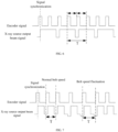
- FIG. 5 and FIG. 6 show that in a uniform speed state, one or more encoder cycles may correspond to one actual output beam time interval of the X-ray source
- FIG. 7 and FIG. 8 show that in a variable speed state, i.e., when the belt speed fluctuates, one or more encoder cycles may correspond to one actual output beam time interval of the X-ray source.
- the encoder has a low precision.
- the X-ray source is controlled to select H source points for a continuous output beam in the preset source point output beam sequence, and H*S>S 0 is satisfied.
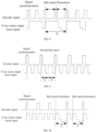
- FIG. 9 shows that in a uniform speed state, one encoder cycle may correspond to two actual output beam time intervals of the X-ray source
- FIG. 10 shows that in a variable speed state, i.e., when the belt speed fluctuates, one encoder cycle may correspond to two actual output beam time intervals of the X-ray source.
- FIG. 3 schematically shows a flow chart of another implementation manner of a method for controlling an output beam of an X-ray source in an imaging system according to an embodiment of the present disclosure, including operation S280.
- a position Z of an object to be scanned on the conveying device is determined during an output beam of the H source points based on the actual output beam time interval T.
- a position coordinate of the object on the conveying device is precisely calculated according to the output beam time of the source point in the X-ray source.
- a device for controlling an output beam of an X-ray source in an imaging system According to the embodiments of the present disclosure, there is further provided a device for controlling an output beam of an X-ray source in an imaging system. The device will be described in detail below with reference to FIG. 11 .
- FIG. 11 schematically shows a structural block diagram of a device for controlling an output beam of an X-ray source in an imaging system according to an embodiment of the present disclosure.
- the device 300 for controlling an output beam of an X-ray source in an imaging system includes: a receiving module 301, a counting module 302, an actual output beam time interval determining module 303, a gap time determining module 304, and an X-ray source controlling module 305.
- the receiving module is used to receive an encoder signal and an X-ray source output beam signal, and initially synchronize the encoder signal and the X-ray source output beam signal.
- the receiving module 301 may be used to perform the operation S210 described above, which is not repeated here.
- the counting module 302 is used to record a coded value M of the encoder at moment t m , and a coded value N of the encoder at moment t m+1 , where each of M, N, and m is an integer. In an embodiment, the counting module 302 may be used to perform the operation S220 described above, which is not repeated here.
- the actual output beam time interval determining module 303 is used to determine that a duration from the moment t m to the moment t m+1 is an actual output beam time interval T of the X-ray source, when it is determined that a difference value between the coded value M and the coded value N satisfies a preset value a, a being an integer.
- the actual output beam time interval determining module 303 may be used to perform the operation S230 described above, which is not repeated here.
- the gap time determining module 304 is used to determine a gap time T G in the actual output beam time interval T based on a preset output beam time interval T J of the imaging system and the actual output beam time interval T. In an embodiment, the gap time determining module 304 may be used to perform the operation S240 described above, which is not repeated here.
- the X-ray source controlling module 305 is used to control the X-ray source not to emit an X-ray beam within the gap time T G .
- the X-ray source controlling module 305 may be used to perform the operation S250 described above, which is not repeated here.
- the device for controlling an output beam of an X-ray source in an imaging system further includes: a first demarcating module used to demarcate a conveying distance S 0 of a conveying device under a single change of the coded value; and an X-ray source output beam state controlling module used to control an output beam state of a source point in the X-ray source according to a numerical relationship between the conveying distance S 0 and a sampling spacing S preset in the imaging system.
- the device for controlling an output beam of an X-ray source in an imaging system further includes: a position calculating module used to determine a position Z of an object to be scanned on a conveying device during an output beam of H source points based on the actual output beam time interval T.
- a method for controlling an output beam of an X-ray source in an imaging system includes: receiving an encoder signal and an X-ray source output beam signal, and initially synchronizing the encoder signal and the X-ray source output beam signal; recording a coded value M of the encoder at moment t m , and a coded value N of the encoder at moment t m+1 , where each of M, N, and m is an integer; determining that a duration from the moment t m to the moment t m+1 is an actual output beam time interval T of the X-ray source, when it is determined that a difference value between the coded value M and the coded value N satisfies a preset value a, where a is an integer; determining a gap time T G in the actual output beam time interval T based on a preset output beam time interval T J of the imaging system and the actual output beam time interval T; and controlling the X-ray source not
- the output beam time of the X-ray source is determined in a manner that the coded value of the encoder changes by a value which is the same as the duration for the change.
- the duration for the change which is the same as the value by which the coded value changes increases. Accordingly, the X-ray source is controlled not to output a beam within the gap time by calculating the increased duration to increase the gap time in the actual output beam time interval of the X-ray source, thereby achieving an equidistant output beam of the X-ray source, so as to avoid the problem of a sampling image disorder caused by an overlapping of the source point output beam time.
- any number of modules from the receiving module 301, the counting module 302, the actual output beam time interval determining module 303, the gap time determining module 304, and the X-ray source controlling module 305 may be combined into one module for implementation, or any one of these modules may be split into a plurality of modules. Alternatively, at least a portion of the functions of one or more of these modules may be combined with at least a portion of the functions of other modules for implementation in one module.
- At least one of the receiving module 301, the counting module 302, the actual output beam time interval determining module 303, the gap time determining module 304, and the X-ray source controlling module 305 may be at least partially implemented as a hardware circuit, such as a Field Programmable Gate Array (FPGA), a Programmable Logic Array (PLA), a System on Chip, a System on Substrate, a System on Package, and an Application Specific Integrated Circuit (ASIC), or may be implemented by a hardware or a firmware in any other reasonable manner of integrating or encapsulating a circuit, or by any one of or by an appropriate combination of more of a software, a hardware, and a firmware.
- FPGA Field Programmable Gate Array
- PLA Programmable Logic Array
- ASIC Application Specific Integrated Circuit
- At least one of the receiving module 301, the counting module 302, the actual output beam time interval determining module 303, the gap time determining module 304, and the X-ray source controlling module 305 may be at least partially implemented as a computer program module, and the computer program module may execute a corresponding function, when it is operated.
- a CT imaging system including: a device for controlling an output beam of an X-ray source in an imaging system according to the embodiments above, an X-ray source having at least one source point in the X-ray source; a detector; a conveying device, an encoder being provided on a rotating shaft of the conveying device; a data collecting module used to acquire data information collected by the detector; a data processing module used to receive the data information uploaded by the data collecting module, and perform an image reconstruction according to the data information; and a display module used to display a result of the image reconstruction.
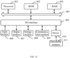
- FIG. 12 schematically shows a block diagram of an electronic apparatus applicable for implementing a method for splicing moving targets in a fixed view field according to an embodiment of the present disclosure.
- the electronic device 400 includes a processor 401 that may perform various appropriate actions and processes according to a program stored in a read-only memory (ROM) 402 or a program loaded from a memory section 408 into a random access memory (RAM) 403.
- the processor 401 may include, for example, a general-purpose microprocessor (e.g., a CPU), an instruction set processor and/or a related chipset, and/or a special-purpose microprocessor (e.g., an application-specific integrated circuit (ASIC)), and the like.
- the processor 401 may also include an on-board memory for a caching purpose.
- the processor 401 may include a single processing unit or multiple processing units for performing different actions of the method flow according to the embodiments of the present disclosure.
- the processor 401 In the RAM 403, various programs and data necessary for an operation of the electronic apparatus 400 are stored.
- the processor 401, the ROM 402, and the RAM 403 are connected to one another through a bus 404.
- the processor 401 performs various operations of the method flow according to the embodiments of the present disclosure by executing the program in the ROM 402 and/or the RAM 403. It is noted that the program may also be stored in one or more memories other than the ROM 402 and the RAM 403.
- the processor 401 may also perform various operations of the method flow according to the embodiments of the present disclosure by executing programs stored in the one or more memories.
- the electronic apparatus 400 may further include an input/output (I/O) interface 405.
- the input/output (I/O) interface 405 is also connected to the bus 404.
- the electronic apparatus 400 may also include one or more of the following components connected to the I/O interface 405: an 1 406 including a keyboard, a mouse, etc.; an output section 407 including a cathode ray tube (CRT), a liquid crystal display (LCD), a speaker, etc.; a storage section 408 including a hard disk and the like; and a communication section 405 including a network interface card such as a LAN card and a modem.
- the communication section 405 performs a communication processing via a network such as the Internet.
- a driver 410 is also connected to the I/O interface 405 as needed.
- a detachable medium 411 such as a magnetic disk, an optical disk, a magneto-optical disk and a semiconductor memory, is installed on the driver 410 as needed, so that the computer program read therefrom is installed into the storage section 408 as needed.
- a computer-readable storage medium may be included in the device/apparatus/system described in the above embodiments. It may also exist alone without being assembled into the device/apparatus/system.
- the above computer-readable storage medium carries one or more programs, and when the above one or more programs are executed, the method according to the embodiments of the present disclosure is implemented.
- the computer-readable storage medium may be a non-volatile computer-readable storage medium, for example, including but not limited to, a portable computer disk, a hard disk, a random access memory (RAM), a read only memory (ROM), an erasable programmable read only memory (EPROM or a flash memory), a portable compact disk read only memory (CD-ROM), an optical storage device, a magnetic storage devices, or any suitable combination of the above.
- a computer-readable storage medium may be any tangible medium that contains or stores a program. The program may be used by or in combination with an instruction execution system, an apparatus, or a device.
- a computer-readable storage medium may include one or more memories other than the ROM 402 and/or the RAM 403 and/or the ROM 402 and the RAM 403 described above.
- a computer program product including a computer program, the computer program containing a program code for performing the method illustrated in the flowchart.
- the program code is used to cause the computer system to implement the item recommendation method provided in the embodiments of the present disclosure.
- the computer program performs the above functions defined in the system/apparatus of the embodiments of the present disclosure, when it is executed by the processor 401.
- the system, apparatus, module, unit, etc. described above may be implemented by a computer program module.
- the computer program may rely on a tangible storage medium such as an optical storage device and a magnetic storage device.
- the computer program may also be transmitted and distributed in the form of a signal over a network medium, and downloaded and installed through the communication section 405, and/or installed from the detachable medium 411.
- the program code contained in the computer program may be transmitted using any suitable network medium, including but not limited to: a wireless network medium, a wired network medium, etc., or any suitable combination of the above.
- the computer program may be downloaded and installed from the network via the communication section 405 and/or installed from the detachable medium 411.
- the above functions defined in the system of the embodiments of the present disclosure are performed.
- the above system, apparatus, device, module, unit, etc. may be implemented by a computer program module.
- the program code for executing the computer program provided in the embodiments of the present disclosure may be written in any combination of one or more programming languages. Specifically, advanced procedures and/or object-oriented programming languages, and/or assembly/machine languages may be used to implement these computing programs.
- Programming languages include, but are not limited to, languages such as Java, C++, python, "C" language or similar programming languages.
- the program code may be executed entirely on a user computing device, partially on the user device, partially on a remote computing device, or entirely on a remote computing device or server.
- the remote computing device may be connected to a user computing device over any kind of network, including a local area network (LAN) or a wide area network (WAN), or may be connected to an external computing device (for example, connection over the Internet using an Internet service provider).
- LAN local area network
- WAN wide area network
- an Internet service provider for example, connection over the Internet using an Internet service provider
- each block in the flowcharts or block diagrams may represent a module, a program segment, or a portion of a code, the above module, program segment, or portion of the code includes one or more executable instructions for implementing specified logical functions.
- the functions noted in the blocks may occur in a sequence different from the sequence as noted in the figures. For example, two blocks shown in a successive manner may be actually executed substantially concurrently, or the blocks may be sometimes executed in a reverse sequence depending on the function involved.
- each block in the block diagrams or flowcharts and combinations of blocks in the block diagrams or flowcharts may be achieved by a dedicated hardware-based system for executing specified functions or operations.
Landscapes
- Health & Medical Sciences (AREA)
- Physics & Mathematics (AREA)
- General Physics & Mathematics (AREA)
- General Health & Medical Sciences (AREA)
- Life Sciences & Earth Sciences (AREA)
- Engineering & Computer Science (AREA)
- Theoretical Computer Science (AREA)
- Pathology (AREA)
- Chemical & Material Sciences (AREA)
- Analytical Chemistry (AREA)
- Biochemistry (AREA)
- Immunology (AREA)
- Toxicology (AREA)
- Nuclear Medicine, Radiotherapy & Molecular Imaging (AREA)
- Pulmonology (AREA)
- Radiology & Medical Imaging (AREA)
- High Energy & Nuclear Physics (AREA)
- General Life Sciences & Earth Sciences (AREA)
- Geophysics (AREA)
- Analysing Materials By The Use Of Radiation (AREA)
- Length Measuring Devices By Optical Means (AREA)
Abstract
Description
- The present disclosure relates to a field of security inspection imaging technology, and in particularly, to a method and a device for controlling an output beam of an X-ray source in an imaging system, a CT imaging system, an electronic apparatus, a storage medium and a program product.
- Reconstruction of a CT image is based on a known precise geometry of a source point of X-ray source, a detector crystal, and a scanned object in the same coordinate system. To ensure the quality of a reconstructed image, an X-ray beam should be ensured to have a uniform sampling frequency in time and space as much as possible. Typically, a temporal sampling frequency is strictly controlled by a detector integration time, while a spatial sampling frequency is controlled by a uniform motion of an equipment conveying device. However, due to an influence of the load, the speed of the equipment conveying device fluctuates, especially when the equipment conveying device stops and then resumes for some reason, the spatial sampling frequency and the temporal sampling frequency are not synchronous, resulting in a distortion or disorder of the reconstructed image.
- In view of this, according to the embodiments of the present disclosure, there is provided a method and a device for controlling an output beam of an X-ray source in an imaging system, a CT imaging system, an electronic apparatus, a storage medium and a program product.
- According to an aspect of the present disclosure, there is provided a method for controlling an output beam of an X-ray source in an imaging system. The imaging system includes an X-ray source, a detector, a conveying device and an encoder arranged on the conveying device. The method includes: receiving an encoder signal and an X-ray source output beam signal, and initially synchronizing the encoder signal and the X-ray source output beam signal; recording a coded value M of the encoder at moment tm, and a coded value N of the encoder at moment tm+1, where each of M, N, and m is an integer; determining that a duration from the moment tm to the moment tm+1 is an actual output beam time interval T of the X-ray source, when it is determined that a difference value between the coded value M and the coded value N satisfies a preset value a, where a is an integer; determining a gap time TG in the actual output beam time interval T based on a preset output beam time interval TJ of the imaging system and the actual output beam time interval T; and controlling the X-ray source not to emit an X-ray beam within the gap time TG.
- According to the embodiments of the present disclosure, the method for controlling an output beam of an X-ray source in an imaging system further includes: demarcating a conveying distance S0 of the conveying device under a single change of the coded value; and controlling an output beam state of a source point in the X-ray source according to a numerical relationship between the conveying distance S0 and a sampling spacing S preset in the imaging system.
- According to the embodiments of the present disclosure, when S0≤S, in a single actual output beam time interval T, the X-ray source is controlled to select a source point for an output beam in a preset source point output beam sequence.
- According to the embodiments of the present disclosure, when the X-ray source is controlled to select a source point for an output beam in a preset source point output beam sequence, the preset output beam time interval is TJ=a*S0/v, where v is a speed set in the conveying device.
- According to the embodiments of the present disclosure, when S0≥S, in a single actual output beam time interval T, the X-ray source is controlled to select H source points for a continuous output beam in a preset source point output beam sequence, and H*S>S0 is satisfied.
- According to the embodiments of the present disclosure, when the X-ray source is controlled to select H source points for a continuous output beam in a preset source point output beam sequence, the preset output beam time interval is TJ=S0/(H*v), where v is a speed set in the conveying device.
- According to the embodiments of the present disclosure, a position Z of an object to be scanned on the conveying device during an output beam of the H source points is determined based on the actual output beam time interval T.
- According to the embodiments of the present disclosure, the determining a position Z of an object to be scanned on the conveying device during an output beam of the H source points based on the actual output beam time interval T includes: demarcating a first output beam when the encoder signal and the X-ray source output beam signal are initially synchronized; and calculating Z=(k-1)*S0+TJ*S0/(T1+T2), where T1 is a duration of a K-1th output beam, and T2 is a duration of a Kth output beam.
- According to the embodiments of the present disclosure, the determining a gap time TG in the actual output beam time interval T based on a preset output beam time interval TJ of the imaging system and the actual output beam time interval T includes: TG=T-TJ.
- According to another aspect of the present disclosure, there is provided a device for controlling an output beam of an X-ray source in an imaging system, including: a receiving module configured to receive an encoder signal and an X-ray source output beam signal, and initially synchronize the encoder signal and the X-ray source output beam signal; a counting module configured to record a coded value M of the encoder at moment tm, and a coded value N of the encoder at moment tm+1, where each of M, N, and m is an integer; an actual output beam time interval determining module configured to determine that a duration from the moment tm to the moment tm+1 is an actual output beam time interval T of the X-ray source, when it is determined that a difference value between the coded value M and the coded value N satisfies a preset value a, a being an integer; a gap time determining module configured to determine a gap time TG in the actual output beam time interval T based on a preset output beam time interval TJ of the imaging system and the actual output beam time interval T; and an X-ray source controlling module configured to control the X-ray source not to emit an X-ray beam within the gap time TG.
- According to the embodiments of the present disclosure, the device for controlling an output beam of an X-ray source in an imaging system further includes: a first demarcating module configured to demarcate a conveying distance S0 of a conveying device under a single change of the coded value; and an X-ray source output beam state controlling module configured to control an output beam state of a source point in the X-ray source according to a numerical relationship between the conveying distance S0 and a sampling spacing S preset in the imaging system.
- According to another aspect of the present disclosure, there is further provided a CT imaging system, including: an X-ray source having at least one source point in the X-ray source; a detector; a conveying device, an encoder being provided on a rotating shaft of the conveying device; a data collecting module configured to acquire data information collected by the detector; a data processing module configured to receive the data information uploaded by the data collecting module, and perform an image reconstruction according to the data information; a display module configured to display a result of the image reconstruction; and a device for controlling an output beam of an X-ray source in an imaging system according to any one of the above.
- According to the embodiments of the present disclosure, a position calculating module is further included and configured to determine a position Z of an object to be scanned on a conveying device during an output beam of H source points based on the actual output beam time interval T.
- According to another aspect of the present disclosure, there is further provided an electronic apparatus, including: one or more processors; and a storage device configured to store one or more programs, wherein when the one or more programs are executed by the one or more processors, the one or more processors are caused to execute the method according to any one of the above.
- According to another aspect of the present disclosure, there is further provided a computer-readable storage medium having an executable instruction stored thereon, the instruction, when executed by a processor, causing the processor to perform the method according to any one of the above.
- According to another aspect of the present disclosure, there is further provided a computer program product, including a computer program, the computer program, when executed by a processor, implementing the method according to any one of the above.
- According to the embodiments of the present disclosure, there is provided a method for controlling an output beam of an X-ray source in an imaging system. The method includes: receiving an encoder signal and an X-ray source output beam signal, and initially synchronizing the encoder signal and the X-ray source output beam signal; recording a coded value M of the encoder at moment tm, and a coded value N of the encoder at moment tm+1, where each of M, N, and m is an integer; determining that a duration from the moment tm to the moment tm+1 is an actual output beam time interval T of the X-ray source, when it is determined that a difference value between the coded value M and the coded value N satisfies a preset value a, where a is an integer; determining a gap time TG in the actual output beam time interval T based on a preset output beam time interval TJ of the imaging system and the actual output beam time interval T; and controlling the X-ray source not to emit a beam within the gap time TG. In the embodiments of the present disclosure, the output beam time of the X-ray source is determined in a manner that the coded value of the encoder changes by a value which is the same as the duration for the change. When the speed of the conveying device decreases, the duration for the change which is the same as the value by which the coded value changes increases. Accordingly, the X-ray source is controlled not to output a beam within the gap time by calculating the increased duration to increase the gap time in the actual output beam time interval of the X-ray source, thereby achieving an equidistant output beam of the X-ray source, so as to avoid the problem of a sampling image disorder caused by an overlapping of the source point output beam time.
- The above and other objectives, features and advantages of the present disclosure will become more apparent from the following description of the embodiments of the present disclosure with reference to the accompanying drawings. In the drawings,
-
FIG. 1 schematically shows a flowchart of a method for controlling an output beam of an X-ray source in an imaging system according to the embodiments of the present disclosure; -
FIG. 2 schematically shows a flow chart of another implementation manner of a method for controlling an output beam of an X-ray source in an imaging system according to the embodiments of the present disclosure; -
FIG. 3 schematically shows a flow chart of another implementation manner of a method for controlling an output beam of an X-ray source in an imaging system according to the embodiments of the present disclosure; -
FIG. 4 schematically shows a schematic diagram of an actual output beam time interval of an X-ray source output beam signal in a method for controlling an output beam of an X-ray source in an imaging system according to the embodiments of the present disclosure; -
FIG. 5 schematically shows a schematic diagram of an encoder signal and an X-ray source output beam signal in a method for controlling an output beam of an X-ray source in an imaging system according to the embodiments of the present disclosure; -
FIG. 6 schematically shows a schematic diagram of an encoder signal and an X-ray source output beam signal in an imaging system according to the embodiments of the present disclosure. -
FIG. 7 schematically shows a schematic diagram of an encoder signal and an X-ray source output beam signal in another implementation manner of a method for controlling an output beam of an X-ray source in an imaging system according to the embodiments of the present disclosure; -
FIG. 8 schematically shows a schematic diagram of an encoder signal and an X-ray source output beam signal in another implementation manner of a method for controlling an output beam of an X-ray source in an imaging system according to the embodiments of the present disclosure; -
FIG. 9 schematically shows a schematic diagram of an encoder signal and an X-ray source output beam signal in another implementation manner of a method for controlling an output beam of an X-ray source in an imaging system according to the embodiments of the present disclosure; -
FIG. 10 schematically shows a schematic diagram of an encoder signal and an X-ray source output beam signal in another implementation manner of a method for controlling an output beam of an X-ray source in an imaging system according to the embodiments of the present disclosure; -
FIG. 11 schematically shows a structural block diagram of a device for controlling an output beam of an X-ray source in an imaging system according to the embodiments of the present disclosure; -
FIG. 12 schematically shows a block diagram of an electronic apparatus applicable for implementing a method for controlling an output beam of an X-ray source in an imaging system according to the embodiments of the present disclosure. - Hereinafter, the embodiments of the present disclosure will be described with reference to the accompanying drawings. However, it should be understood that these descriptions are exemplary only, and are not intended to limit the scope of the present disclosure. In the following detailed description, for convenience of explanation, numerous specific details are set forth in order to provide a thorough understanding of the embodiments of the present disclosure. However, it will be apparent that one or more embodiments may be implemented without these specific details. In addition, in the following description, descriptions of well-known structures and technologies are omitted to avoid unnecessarily obscuring the concepts of the present disclosure.
- The terms used here are only for the purpose of describing particular embodiments and are not intended to limit the present disclosure. The terms "comprise", "include" and the like used here indicate the presence of a features, a operation, an operation and/or a component, but do not exclude the presence or addition of one or more other features, operations, operations or components.
- When an expression like "at least one of A, B, or C" is used, it should generally be interpreted in accordance with the meaning of the expression commonly understood by those skilled in the art (e.g., "a system having at least one of A, B, or C" should include, but not be limited to a system having A only, having B only, having C only, having A and B, having A and C, having B and C, and/or having A, B and C). The terms "first" and "second" are only used for descriptive purposes, and should not be construed as indicating or implying relative importance or impliedly indicating the quantity of technical features indicated. Therefore, features defined with "first" and "second" may expressly or impliedly include one or more of said features.
- The detailed background technology may include other technical problems in addition to the technical problems to be solved by the independent claims.
- In the field of radiation imaging, when a static CT scanning system with a distributed X-ray source is used, a position of a source point of the X-ray source is fixed and unchanged, and a control system controls the source point for a quick switch and output beam. The positions of a X-ray source and a detector of a static CT are fixed and unchanged, and a very small error may occur after a geometric demarcation is performed. If a CT detector performs sampling at a fixed time interval, a scanned object moves along a conveyor belt, and a speed fluctuation of the conveyor belt will cause an erroneous coordinate position of the object in a conveying direction.
- In a static CT system with a single scan plane, a belt speed fluctuation may cause a distortion of a reconstructed image.
- In a static CT system with multiple scan planes, a belt speed fluctuation may result in disorder of reconstruction data. Especially when the conveyor belt is stopped and then resumed, the distortion or disorder of an image will be more obvious, which will seriously affect the accuracy of an image judgment.
- The inventor found out that there are generally two approaches to deal with the above belt speed fluctuation.
- The first approach is to restore a package to a position of a uniform motion by rewinding, and then reconstruct an image according to a uniform speed state. But the operation of this approach is relatively complicated, and a high control accuracy of the conveying device is required.
- The second approach is to demarcate a position of a package of each output beam by coding. This approach is easy to make the number of reconstructed viewing angles of different slices vary greatly, resulting in an image difference.
- In view of the above problems, according to the embodiments of the present disclosure, there is provided a method for controlling an output beam of an X-ray source in an imaging system. The imaging system includes an X-ray source, a detector, a conveying device and an encoder arranged on the conveying device. The method includes: receiving an encoder signal and an X-ray source output beam signal, and initially synchronizing the encoder signal and the X-ray source output beam signal; recording a coded value M of the encoder at moment tm, and a coded value N of the encoder at moment tm+1, where each of M, N, and m is an integer; determining that a duration from the moment tm to the moment tm+1 is an actual output beam time interval T of the X-ray source, when it is determined that a difference value between the coded value M and the coded value N satisfies a preset value a, where a is an integer; determining a gap time TG in the actual output beam time interval T based on a preset output beam time interval TJ of the imaging system and the actual output beam time interval T; and controlling the X-ray source not to emit an X-ray beam within the gap time TG.
- In the embodiments of the present disclosure, the output beam time of the X-ray source is determined in a manner that the coded value of the encoder changes by a value which is the same as the duration for the change. When the speed of the conveying device decreases, the duration for the change which is the same as the value by which the coded value changes increases. Accordingly, the X-ray source is controlled not to output a beam within the gap time by calculating the increased duration to increase the gap time in the actual output beam time interval of the X-ray source, thereby achieving an equidistant output beam of the X-ray source, so as to avoid the problem of a sampling image disorder caused by an overlapping of the source point output beam time.
-
FIG. 1 schematically shows a flow chart of a method for controlling an output beam of an X-ray source in an imaging system according to an embodiment of the present disclosure. - As shown in
FIG. 1 , the method for controlling an output beam of an X-ray source in an imaging system according to this embodiment of the present disclosure includes operation S210 to operation S250. - In operation 210, an encoder signal and an X-ray source output beam signal are received, and the encoder signal and the X-ray source output beam signal are initially synchronized.
- It should be noted that the usage scenario of the method in the embodiments of the present disclosure is a static CT scanning system with a distributed X-ray source. A static CT scanning system with a distributed X-ray source basically includes an X-ray source, a detector and a conveying device. The X-ray source and the detector are fixed and unchanged, and a scanning region is formed in a certain region of the conveying device. The conveying device is responsible for conveying an object to be detected to the scanning region. A plurality of source points are set in the X-ray source. The source points may emit X-rays for scanning an object. The plurality of source points may be set at intervals along a conveying direction. When an object is scanned, different source points perform an output beam action in a certain sequence according to scanning requirements.
- It may be understood that an X-ray source output beam signal described in the present text is an output beam signal of a source point described above.
- It may be understood that according to the basic principle of radiation imaging, a ray emitted by the X-ray source is received by the detector, and the system controls the output beam action of the X-ray source to synchronize with the receiving action of the detector to ensure the quality of imaging. The synchronization of the output beam action of the X-ray source with the receiving action of the detector may be a default operation of the system. Therefore, in the present text, a representative description is made only using the X-ray source output beam signal to make the illustration concise.
- In the embodiments of the present disclosure, the encoder is set on the conveying device. For example, the conveying device may be a belt conveyor, and the encoder may be installed on a driving roller of the belt conveyor to detect an angular velocity of the driving roller, thereby calculating a moving speed, a moving distance etc. of the detected object on the conveying device.
- It may be understood that the encoder may be of a code disc type, a code ruler type, or the like.
- It may be understood that a background server or a system general controller receives the encoder signal and the X-ray source output beam signal. On the basis that in the present disclosure an output beam situation of the X-ray source is determined through the encoder signal fed back by the encoder, it is necessary to ensure the synchronization of the encoder signal with the X-ray source signal. The synchronization of the encoder signal with the X-ray source signal may be achieved by controlling start-up signals of the encoder and the X-ray source.
- In
operation 220, a coded value M of the encoder at moment tm and a coded value N of the encoder at moment tm+1 are is recorded, where each of M, N, and m is an integer. - It may be understood that, when an encoder of a code disc type is taken as an example, the encoder converts an angular displacement into a periodic electrical signal, and then converts the electrical signal into a count pulse, and a quantity of count pulses is used to represent a displacement value. A zero pulse is used to demarcate a zero reference position of the encoder and the position of the detected object on the conveying device at the zero reference position. For example, at the zero reference position, the first source point in the X-ray source emits an X-ray beam, and moment t0 is demarcated at a time cycle.
- In the embodiments of the present disclosure, a single change of a coded value is used to define a unit moving distance of a detected object. For example, when the object moves 10 mm, the coded value changes by 1. At different moments, the detected object is driven by the conveying device to move, and the coded value increases by one for every 10mm increase in the moving distance of the object.
- In operation S230, it is determined that a duration from the moment tm to the moment tm+1 is an actual output beam time interval T of the X-ray source, when it is determined that a difference value between the coded value M and the coded value N satisfies a preset value a, where a is an integer.
- In the embodiments of the present disclosure, when a change amount of the coded value of the encoder reaches the preset value a, it means that the detected object reaches a preset distance of the system. The actual output beam time interval T of the X-ray source may be obtained by calculating a time required for a change of the coded value.
- In operation S240, a gap time TG in the actual output beam time interval T is determined based on a preset output beam time interval TJ of the imaging system and the actual output beam time interval T.
- It may be understood that in an ideal state, after a preset time interval of an actual output beam, the X-ray source emits a beam with a second source point according to the sequence. At the same time, the conveying device needs to convey the detected object by a preset distance, but when the belt speed fluctuates, the conveying device does not move by the preset distance, after the X-ray source outputs an X-ray beam at the preset time interval of the output beam.
- It may be understood that when the belt speed fluctuates, the duration required for conveying the detected object by the preset distance increases, which is represented by the gap time TG above, and therefore TG=T-TJ.
- As shown in
FIG. 4 , in the embodiments of the present disclosure, the actual output beam time interval of a single source point may be divided into three parts: on time, off time and gap time. On time and off time are fixed durations preset in the system, and respectively represent a stable dose interval and a rising and falling dose interval. Off time may be located on one side or both sides of on time, and a sum of on time and off time is the preset output beam time interval TJ described above. When the belt speed is normal, the actual output beam time interval of the source point is only constituted by two parts: on time and off time. Gap time is the gap time TG described above. When the belt speed fluctuates, the gap time TG is increased in the actual output beam time interval of the source point. - In operation S250, the X-ray source is controlled not to emit an X-ray beam within the gap time TG.
- In the embodiments of the present disclosure, the source point in the X-ray source is controlled not to output a beam during the gap time.
-
FIG. 2 schematically shows a flow chart of another implementation manner of a method for controlling an output beam of an X-ray source in an imaging system according to an embodiment of the present disclosure, including operations S260 to S270. - In operation S260, a conveying distance S0 of the conveying device is demarcated under a single change of the coded value.
- In operation S270, an output beam state of a source point in the X-ray source is controlled according to a numerical relationship between the conveying distance S0 and a sampling spacing S preset in the imaging system.
- The output beam state of a source point in the X-ray source is affected by the accuracy of the encoder as follows.
- When the S0≤S, i.e., the encoder has a high precision, in a single actual output beam time interval T, the X-ray source is controlled to select one source point for an output beam in a preset source point output beam sequence. For example,
FIG. 5 andFIG. 6 show that in a uniform speed state, one or more encoder cycles may correspond to one actual output beam time interval of the X-ray source, andFIG. 7 andFIG. 8 show that in a variable speed state, i.e., when the belt speed fluctuates, one or more encoder cycles may correspond to one actual output beam time interval of the X-ray source. - In the embodiments of the present disclosure, when the X-ray source is controlled to select a source point to output a beam in a preset output beam sequence of source points, the preset output beam time interval is TJ=a*S0/v, where v is a speed set in the conveying device.
- When the S0≥S, the encoder has a low precision. In a single actual output beam time interval T, the X-ray source is controlled to select H source points for a continuous output beam in the preset source point output beam sequence, and H*S>S0 is satisfied. For example,
FIG. 9 shows that in a uniform speed state, one encoder cycle may correspond to two actual output beam time intervals of the X-ray source, andFIG. 10 shows that in a variable speed state, i.e., when the belt speed fluctuates, one encoder cycle may correspond to two actual output beam time intervals of the X-ray source. - When the X-ray source is controlled to select H source points for a continuous output beam in the preset source point output beam sequence, the preset output beam time interval is TJ=S0/(H*v), where v is a speed set in the conveying device.
-
FIG. 3 schematically shows a flow chart of another implementation manner of a method for controlling an output beam of an X-ray source in an imaging system according to an embodiment of the present disclosure, including operation S280. - In operation S280, a position Z of an object to be scanned on the conveying device is determined during an output beam of the H source points based on the actual output beam time interval T.
- In the embodiments of the present disclosure, for the situation of the encoder having a low precision, i.e., when S0≥S, in order to further improve the quality of the reconstructed image, when each source point outputs a beam, a position coordinate of the object on the conveying device is precisely calculated according to the output beam time of the source point in the X-ray source.
- It is demarcated that when the encoder signal is initially synchronized with the X-ray source output beam signal, a first output beam occurs. Z=(k-1)*S0+TJ*S0/(T1+T2) is calculated, where T1 is a duration of a K-1th output beam, T2 is a duration of a Kth, output beam, and Z represents the position of the detected object on the conveying device.
- Based on the above method for controlling an output beam of an X-ray source in an imaging system, according to the embodiments of the present disclosure, there is further provided a device for controlling an output beam of an X-ray source in an imaging system. The device will be described in detail below with reference to
FIG. 11 . -
FIG. 11 schematically shows a structural block diagram of a device for controlling an output beam of an X-ray source in an imaging system according to an embodiment of the present disclosure. - As shown in
FIG. 11 , thedevice 300 for controlling an output beam of an X-ray source in an imaging system includes: a receivingmodule 301, acounting module 302, an actual output beam timeinterval determining module 303, a gaptime determining module 304, and an X-raysource controlling module 305. - The receiving module is used to receive an encoder signal and an X-ray source output beam signal, and initially synchronize the encoder signal and the X-ray source output beam signal. In an embodiment, the receiving
module 301 may be used to perform the operation S210 described above, which is not repeated here. - The
counting module 302 is used to record a coded value M of the encoder at moment tm, and a coded value N of the encoder at moment tm+1, where each of M, N, and m is an integer. In an embodiment, thecounting module 302 may be used to perform the operation S220 described above, which is not repeated here. - The actual output beam time
interval determining module 303 is used to determine that a duration from the moment tm to the moment tm+1 is an actual output beam time interval T of the X-ray source, when it is determined that a difference value between the coded value M and the coded value N satisfies a preset value a, a being an integer. In an embodiment, the actual output beam timeinterval determining module 303 may be used to perform the operation S230 described above, which is not repeated here. - The gap
time determining module 304 is used to determine a gap time TG in the actual output beam time interval T based on a preset output beam time interval TJ of the imaging system and the actual output beam time interval T. In an embodiment, the gaptime determining module 304 may be used to perform the operation S240 described above, which is not repeated here. - The X-ray
source controlling module 305 is used to control the X-ray source not to emit an X-ray beam within the gap time TG. In an embodiment, the X-raysource controlling module 305 may be used to perform the operation S250 described above, which is not repeated here. - For example, the device for controlling an output beam of an X-ray source in an imaging system according to the embodiments of the present disclosure further includes: a first demarcating module used to demarcate a conveying distance S0 of a conveying device under a single change of the coded value; and an X-ray source output beam state controlling module used to control an output beam state of a source point in the X-ray source according to a numerical relationship between the conveying distance S0 and a sampling spacing S preset in the imaging system.
- For example, the device for controlling an output beam of an X-ray source in an imaging system according to the embodiments of the present disclosure further includes: a position calculating module used to determine a position Z of an object to be scanned on a conveying device during an output beam of H source points based on the actual output beam time interval T.
- According to the embodiments of the present disclosure, there is provided a method for controlling an output beam of an X-ray source in an imaging system. The method includes: receiving an encoder signal and an X-ray source output beam signal, and initially synchronizing the encoder signal and the X-ray source output beam signal; recording a coded value M of the encoder at moment tm, and a coded value N of the encoder at moment tm+1, where each of M, N, and m is an integer; determining that a duration from the moment tm to the moment tm+1 is an actual output beam time interval T of the X-ray source, when it is determined that a difference value between the coded value M and the coded value N satisfies a preset value a, where a is an integer; determining a gap time TG in the actual output beam time interval T based on a preset output beam time interval TJ of the imaging system and the actual output beam time interval T; and controlling the X-ray source not to emit an X-ray beam within the gap time TG. In the embodiments of the present disclosure, the output beam time of the X-ray source is determined in a manner that the coded value of the encoder changes by a value which is the same as the duration for the change. When the speed of the conveying device decreases, the duration for the change which is the same as the value by which the coded value changes increases. Accordingly, the X-ray source is controlled not to output a beam within the gap time by calculating the increased duration to increase the gap time in the actual output beam time interval of the X-ray source, thereby achieving an equidistant output beam of the X-ray source, so as to avoid the problem of a sampling image disorder caused by an overlapping of the source point output beam time.
- According to the embodiments of the present disclosure, any number of modules from the receiving
module 301, thecounting module 302, the actual output beam timeinterval determining module 303, the gaptime determining module 304, and the X-raysource controlling module 305 may be combined into one module for implementation, or any one of these modules may be split into a plurality of modules. Alternatively, at least a portion of the functions of one or more of these modules may be combined with at least a portion of the functions of other modules for implementation in one module. According to the embodiments of the present disclosure, at least one of the receivingmodule 301, thecounting module 302, the actual output beam timeinterval determining module 303, the gaptime determining module 304, and the X-raysource controlling module 305 may be at least partially implemented as a hardware circuit, such as a Field Programmable Gate Array (FPGA), a Programmable Logic Array (PLA), a System on Chip, a System on Substrate, a System on Package, and an Application Specific Integrated Circuit (ASIC), or may be implemented by a hardware or a firmware in any other reasonable manner of integrating or encapsulating a circuit, or by any one of or by an appropriate combination of more of a software, a hardware, and a firmware. Alternatively, at least one of the receivingmodule 301, thecounting module 302, the actual output beam timeinterval determining module 303, the gaptime determining module 304, and the X-raysource controlling module 305 may be at least partially implemented as a computer program module, and the computer program module may execute a corresponding function, when it is operated. - According to the embodiments of the present disclosure, there is also provided a CT imaging system, including: a device for controlling an output beam of an X-ray source in an imaging system according to the embodiments above, an X-ray source having at least one source point in the X-ray source; a detector; a conveying device, an encoder being provided on a rotating shaft of the conveying device; a data collecting module used to acquire data information collected by the detector; a data processing module used to receive the data information uploaded by the data collecting module, and perform an image reconstruction according to the data information; and a display module used to display a result of the image reconstruction.
-
FIG. 12 schematically shows a block diagram of an electronic apparatus applicable for implementing a method for splicing moving targets in a fixed view field according to an embodiment of the present disclosure. - As shown in
FIG. 12 , the electronic device 400 according to the embodiments of the present disclosure includes aprocessor 401 that may perform various appropriate actions and processes according to a program stored in a read-only memory (ROM) 402 or a program loaded from amemory section 408 into a random access memory (RAM) 403. Theprocessor 401 may include, for example, a general-purpose microprocessor (e.g., a CPU), an instruction set processor and/or a related chipset, and/or a special-purpose microprocessor (e.g., an application-specific integrated circuit (ASIC)), and the like. Theprocessor 401 may also include an on-board memory for a caching purpose. Theprocessor 401 may include a single processing unit or multiple processing units for performing different actions of the method flow according to the embodiments of the present disclosure. - In the
RAM 403, various programs and data necessary for an operation of the electronic apparatus 400 are stored. Theprocessor 401, theROM 402, and theRAM 403 are connected to one another through abus 404. Theprocessor 401 performs various operations of the method flow according to the embodiments of the present disclosure by executing the program in theROM 402 and/or theRAM 403. It is noted that the program may also be stored in one or more memories other than theROM 402 and theRAM 403. Theprocessor 401 may also perform various operations of the method flow according to the embodiments of the present disclosure by executing programs stored in the one or more memories. - According to the embodiments of the present disclosure, the electronic apparatus 400 may further include an input/output (I/O)
interface 405. The input/output (I/O)interface 405 is also connected to thebus 404. The electronic apparatus 400 may also include one or more of the following components connected to the I/O interface 405: an 1 406 including a keyboard, a mouse, etc.; anoutput section 407 including a cathode ray tube (CRT), a liquid crystal display (LCD), a speaker, etc.; astorage section 408 including a hard disk and the like; and acommunication section 405 including a network interface card such as a LAN card and a modem. Thecommunication section 405 performs a communication processing via a network such as the Internet. Adriver 410 is also connected to the I/O interface 405 as needed. Adetachable medium 411, such as a magnetic disk, an optical disk, a magneto-optical disk and a semiconductor memory, is installed on thedriver 410 as needed, so that the computer program read therefrom is installed into thestorage section 408 as needed. - According to the present disclosure, there is also provided a computer-readable storage medium. The computer-readable storage medium may be included in the device/apparatus/system described in the above embodiments. It may also exist alone without being assembled into the device/apparatus/system. The above computer-readable storage medium carries one or more programs, and when the above one or more programs are executed, the method according to the embodiments of the present disclosure is implemented.
- According to the embodiments of the present disclosure, the computer-readable storage medium may be a non-volatile computer-readable storage medium, for example, including but not limited to, a portable computer disk, a hard disk, a random access memory (RAM), a read only memory (ROM), an erasable programmable read only memory (EPROM or a flash memory), a portable compact disk read only memory (CD-ROM), an optical storage device, a magnetic storage devices, or any suitable combination of the above. In the embodiments of the present disclosure, a computer-readable storage medium may be any tangible medium that contains or stores a program. The program may be used by or in combination with an instruction execution system, an apparatus, or a device. For example, according to the embodiments of the present disclosure, a computer-readable storage medium may include one or more memories other than the
ROM 402 and/or theRAM 403 and/or theROM 402 and theRAM 403 described above. - According to the embodiments of the present disclosure, there is further provided a computer program product including a computer program, the computer program containing a program code for performing the method illustrated in the flowchart. When the computer program product runs in a computer system, the program code is used to cause the computer system to implement the item recommendation method provided in the embodiments of the present disclosure.
- The computer program performs the above functions defined in the system/apparatus of the embodiments of the present disclosure, when it is executed by the
processor 401. According to the embodiments of the present disclosure, the system, apparatus, module, unit, etc. described above may be implemented by a computer program module. - In an embodiment, the computer program may rely on a tangible storage medium such as an optical storage device and a magnetic storage device. In another embodiment, the computer program may also be transmitted and distributed in the form of a signal over a network medium, and downloaded and installed through the
communication section 405, and/or installed from thedetachable medium 411. The program code contained in the computer program may be transmitted using any suitable network medium, including but not limited to: a wireless network medium, a wired network medium, etc., or any suitable combination of the above. - In such an embodiment, the computer program may be downloaded and installed from the network via the
communication section 405 and/or installed from thedetachable medium 411. When the computer program is executed by theprocessor 401, the above functions defined in the system of the embodiments of the present disclosure are performed. According to the embodiments of the present disclosure, the above system, apparatus, device, module, unit, etc. may be implemented by a computer program module. - According to the embodiments of the present disclosure, the program code for executing the computer program provided in the embodiments of the present disclosure may be written in any combination of one or more programming languages. Specifically, advanced procedures and/or object-oriented programming languages, and/or assembly/machine languages may be used to implement these computing programs. Programming languages include, but are not limited to, languages such as Java, C++, python, "C" language or similar programming languages. The program code may be executed entirely on a user computing device, partially on the user device, partially on a remote computing device, or entirely on a remote computing device or server. When a remote computing device is involved, the remote computing device may be connected to a user computing device over any kind of network, including a local area network (LAN) or a wide area network (WAN), or may be connected to an external computing device (for example, connection over the Internet using an Internet service provider).
- The flowcharts and block diagrams in the drawings illustrate the architectures, functions, and operations that may be achieved by the system, method and computer program product according to various embodiments of the present disclosure. In this regard, each block in the flowcharts or block diagrams may represent a module, a program segment, or a portion of a code, the above module, program segment, or portion of the code includes one or more executable instructions for implementing specified logical functions. It should also be noted that, in some alternative implementations, the functions noted in the blocks may occur in a sequence different from the sequence as noted in the figures. For example, two blocks shown in a successive manner may be actually executed substantially concurrently, or the blocks may be sometimes executed in a reverse sequence depending on the function involved. It should also be noted that each block in the block diagrams or flowcharts and combinations of blocks in the block diagrams or flowcharts may be achieved by a dedicated hardware-based system for executing specified functions or operations.
- Those skilled in the art may understand that various combinations and/or incorporations of features recited in various embodiments and/or claims of the present disclosure may be made, even if such combinations or incorporations are not explicitly recited in the embodiments of the present disclosure. In particular, various combinations and/or incorporations of the features recited in various embodiments and/or claims of the present disclosure may be made without departing from the spirits and teachings of the present disclosure. All such combinations and/or incorporations fall within the scope of the present disclosure.
- The embodiments of the present disclosure have been described above. However, these examples are only for illustrative purposes, and are not intended to limit the scope of the present disclosure. Although various embodiments are described above separately, this does not mean that the measurements in various embodiments may not be advantageously used in combination. The scope of the present disclosure is defined by the appended claims and the equivalents thereof. Without departing from the scope of the present disclosure, those skilled in the art may make various substitutions and modifications, and these substitutions and modifications should all fall within the scope of the present disclosure.
Claims (16)
- A method for controlling an output beam of an X-ray source in an imaging system, the imaging system comprising an X-ray source, a detector, a conveying device and an encoder arranged on the conveying device, and the method comprising:receiving an encoder signal and an X-ray source output beam signal, and initially synchronizing the encoder signal and the X-ray source output beam signal;recording a coded value M of the encoder at moment tm and a coded value N of the encoder at moment tm+1, where each of M, N, and m is an integer;determining that a duration from the moment tm to the moment tm+1 is an actual output beam time interval T of the X-ray source, when it is determined that a difference value between the coded value M and the coded value N satisfies a preset value a, where a is an integer;determining a gap time TG in the actual output beam time interval T based on a preset output beam time interval TJ of the imaging system and the actual output beam time interval T; andcontrolling the X-ray source not to emit an X-ray beam within the gap time TG.
- The method according to claim 1, further comprising:demarcating a conveying distance S0 of the conveying device under a single change of the coded value; andcontrolling an output beam state of a source point in the X-ray source according to a numerical relationship between the conveying distance S0 and a sampling spacing S preset in the imaging system.
- The method according to claim 2, wherein when S0≤S, in a single actual output beam time interval T, the X-ray source is controlled to select a source point for an output beam in a preset source point output beam sequence.
- The method according to claim 3, wherein when the X-ray source is controlled to select a source point for an output beam in a preset source point output beam sequence,
the preset output beam time interval is TJ=a*S0/v, where v is a speed set in the conveying device. - The method according to claim 2, wherein when S0≥S, in a single actual output beam time interval T, the X-ray source is controlled to select H source points for a continuous output beam in a preset source point output beam sequence, and H*S>S0 is satisfied.
- The method according to claim 5, wherein when the X-ray source is controlled to select H source points for a continuous output beam in a preset source point output beam sequence,
the preset output beam time interval is TJ=S0/(H*v), where v is a speed set in the conveying device. - The method according to claim 5, further comprising:
determining a position Z of an object to be scanned on the conveying device during an output beam of the H source points, based on the actual output beam time interval T. - The method according to claim 7, wherein the determining a position Z of an object to be scanned on the conveying device during an output beam of the H source points based on the actual output beam time interval T comprises:demarcating a first output beam when the encoder signal and the X-ray source output beam signal are initially synchronized; andcalculating Z=(k-1)*S0+TJ*S0/(T1+T2), where T1 is a duration of a K-1th output beam, and T2 is a duration of a Kth output beam.
- The method according to any one of claims 1 to 8, wherein the determining a gap time TG in the actual output beam time interval T based on a preset output beam time interval TJ of the imaging system and the actual output beam time interval T comprises:

- A device for controlling an output beam of an X-ray source in an imaging system, comprising:a receiving module configured to receive an encoder signal and an X-ray source output beam signal, and initially synchronize the encoder signal and the X-ray source output beam signal;a counting module configured to record a coded value M of the encoder at moment tm, and a coded value N of the encoder at moment tm+1, where each of M, N, and m is an integer;an actual output beam time interval determining module configured to determine that a duration from the moment tm to the moment tm+1 is an actual output beam time interval T of the X-ray source, when it is determined that a difference value between the coded value M and the coded value N satisfies a preset value a, where a is an integer;a gap time determining module configured to determine a gap time TG in the actual output beam time interval T based on a preset output beam time interval TJ of the imaging system and the actual output beam time interval T; andan X-ray source controlling module configured to control the X-ray source not to emit an X-ray beam within the gap time TG.
- The device according to claim 10, further comprising:a first demarcating module configured to demarcate a conveying distance S0 of a conveying device under a single change of the coded value; andan X-ray source output beam state controlling module configured to control an output beam state of a source point in the X-ray source according to a numerical relationship between the conveying distance S0 and a sampling spacing S preset in the imaging system.
- The device according to claim 10, further comprising:
a position calculating module configured to determine a position Z of an object to be scanned on a conveying device during an output beam of H source points based on the actual output beam time interval T. - A CT imaging system, comprising:an X-ray source having at least one source point in the X-ray source;a detector;a conveying device, an encoder being provided on a rotating shaft of the conveying device;a data collecting module configured to acquire data information collected by the detector;a data processing module configured to receive the data information uploaded by the data collecting module, and perform an image reconstruction according to the data information;a display module configured to display a result of the image reconstruction; anda device for controlling an output beam of an X-ray source in an imaging system according to any one of claims 10 to 12.
- An electronic apparatus, comprising:one or more processors; anda storage device configured to store one or more programs, whereinwhen the one or more programs are executed by the one or more processors, the one or more processors are caused to execute the method according to any one of claims 1 to 9.
- A computer-readable storage medium having an executable instruction stored thereon, the instruction, when executed by a processor, causing the processor to perform the method according to any one of claims 1 to 9.
- A computer program product, comprising a computer program, the computer program, when executed by a processor, implementing the method according to any one of claims 1 to 9.
Applications Claiming Priority (2)
| Application Number | Priority Date | Filing Date | Title |
|---|---|---|---|
| CN202111310304.4A CN116095932B (en) | 2021-11-05 | 2021-11-05 | Method and device for controlling optical beam output in imaging system, and CT imaging system |
| PCT/CN2022/124586 WO2023078039A1 (en) | 2021-11-05 | 2022-10-11 | Beam output control method and apparatus for optical machine in imaging system, and ct imaging system |
Publications (2)
| Publication Number | Publication Date |
|---|---|
| EP4403111A1 true EP4403111A1 (en) | 2024-07-24 |
| EP4403111A4 EP4403111A4 (en) | 2025-10-15 |
Family
ID=86206871
Family Applications (1)
| Application Number | Title | Priority Date | Filing Date |
|---|---|---|---|
| EP22889065.3A Pending EP4403111A4 (en) | 2021-11-05 | 2022-10-11 | Method and apparatus for controlling beam power for an optical machine in an imaging system and CT imaging system |
Country Status (4)
| Country | Link |
|---|---|
| US (1) | US12188882B2 (en) |
| EP (1) | EP4403111A4 (en) |
| CN (1) | CN116095932B (en) |
| WO (1) | WO2023078039A1 (en) |
Family Cites Families (20)
| Publication number | Priority date | Publication date | Assignee | Title |
|---|---|---|---|---|
| US5119190A (en) * | 1963-03-11 | 1992-06-02 | Lemelson Jerome H | Controlling systems and methods for scanning and inspecting images |
| US4118730A (en) * | 1963-03-11 | 1978-10-03 | Lemelson Jerome H | Scanning apparatus and method |
| GB1595805A (en) * | 1977-02-24 | 1981-08-19 | Emi Ltd | Radiography |
| US4951222A (en) * | 1988-06-09 | 1990-08-21 | Bethlehem Steel Corporation | Method and system for dimensional and weight measurements of articles of manufacture by computerized tomography |
| US9709733B2 (en) * | 2006-09-28 | 2017-07-18 | The Florida International University Board Of Trustees | Hand-held optical probe based imaging system with 3D tracking facilities |
| JP2010522410A (en) * | 2007-03-19 | 2010-07-01 | レオ,ジョセ ムノズ | A system for artificial contrast amplification in image visualization. |
| CN102378598B (en) * | 2009-03-31 | 2014-08-20 | 株式会社日立医疗器械 | X-ray diagnosis equipment and long-length image generation method |
| CN202235412U (en) * | 2011-08-12 | 2012-05-30 | 杭州美诺瓦医疗科技有限公司 | Scanning type digital mammary machine using time delay integral detector |
| JP2015011239A (en) * | 2013-06-28 | 2015-01-19 | キヤノン株式会社 | Optical scanning device and image forming device |
| JP6142742B2 (en) * | 2013-09-02 | 2017-06-07 | ブラザー工業株式会社 | Optical scanning apparatus, image forming apparatus, and sensor signal discrimination method |
| CN104374783B (en) * | 2013-12-26 | 2017-06-16 | 清华大学 | CT system and its method |
| CN203705363U (en) * | 2013-12-26 | 2014-07-09 | 清华大学 | CT system |
| CN105092610B (en) * | 2014-05-14 | 2017-09-26 | 同方威视技术股份有限公司 | Scanning imaging system |
| CN105030267A (en) * | 2015-07-14 | 2015-11-11 | 天津福斯特科技股份有限公司 | X-ray tomographic scanner |
| CN105455839A (en) * | 2015-10-16 | 2016-04-06 | 山东新华医疗器械股份有限公司 | Conical beam CT synchronous control device and control method thereof |
| CN108120729B (en) * | 2017-12-28 | 2024-04-02 | 清华大学 | CT inspection system and CT imaging method |
| CN109174693B (en) * | 2018-10-23 | 2021-04-06 | 上海骄成机电设备有限公司 | Synchronization method of line scanning image acquisition system and rejection device |
| CN109521480A (en) * | 2019-01-04 | 2019-03-26 | 同方威视科技(北京)有限公司 | Radiation examination device and radiation testing method |
| CN110109391B (en) * | 2019-04-26 | 2021-10-22 | 上海联影医疗科技股份有限公司 | Timing control method, device, medical system and medium for medical system |
| CN214409338U (en) * | 2020-12-17 | 2021-10-15 | 北京航星机器制造有限公司 | DR detection device |
-
2021
- 2021-11-05 CN CN202111310304.4A patent/CN116095932B/en active Active
-
2022
- 2022-10-11 EP EP22889065.3A patent/EP4403111A4/en active Pending
- 2022-10-11 WO PCT/CN2022/124586 patent/WO2023078039A1/en not_active Ceased
- 2022-11-04 US US18/052,671 patent/US12188882B2/en active Active
Also Published As
| Publication number | Publication date |
|---|---|
| EP4403111A4 (en) | 2025-10-15 |
| US12188882B2 (en) | 2025-01-07 |
| WO2023078039A1 (en) | 2023-05-11 |
| CN116095932B (en) | 2024-05-24 |
| CN116095932A (en) | 2023-05-09 |
| US20230144259A1 (en) | 2023-05-11 |
Similar Documents
| Publication | Publication Date | Title |
|---|---|---|
| US10495661B2 (en) | Method and device for monitoring state of moving object and system for fast inspecting vehicle | |
| US9552659B2 (en) | X-ray CT device, and image reconfiguration method | |
| JP6055025B2 (en) | Scanning imaging system | |
| AU2019219836B2 (en) | Method, apparatus and system for scanning and imaging | |
| US10410379B2 (en) | Reconstructing an image | |
| CN102753993B (en) | Positron emission computed tomography device, method executed by positron emission computed tomography device, and program | |
| US10288762B2 (en) | Systems and methods for detecting luggage in an imaging system | |
| US12188882B2 (en) | Method and device for controlling output beam of ray machine in imaging system, and CT imaging system | |
| CN111025369B (en) | Method for correcting timing precision by using energy information in PET system | |
| US9778332B2 (en) | Spinning controller for NMR sample tube | |
| US10739442B2 (en) | Pulsing laser spot tracking and decoding | |
| US11086027B2 (en) | Detector strip for x-ray film | |
| EP0608234B1 (en) | Shaft displacement measuring system | |
| WO2024212033A1 (en) | X-ray dose management | |
| EP4421537A1 (en) | Radiation detector, trigger signal generator, and radiation analyzing system | |
| CN120189141A (en) | Abnormality detection method, device, electronic device and computer readable storage medium | |
| KR101118528B1 (en) | Ct system of long sample or short sample | |
| CN102727229A (en) | Method and device for acquiring projection angle in CT device and CT device | |
| CN121115152A (en) | Data acquisition methods, devices, equipment, media and software products | |
| US11407240B2 (en) | Device and method for generating an output signal, formed as a pulse sequence, depending on a sensor signal | |
| JPH0579123B2 (en) | ||
| JP2025098651A (en) | Radiographic apparatus, control method thereof, control apparatus, control method thereof, radiographic system, and program | |
| CN120371233A (en) | Jitter correction method and device for printing equipment, electronic equipment and storage medium | |
| JP2005024523A (en) | Range finder and projector having range finder | |
| US10094950B2 (en) | System and method for detecting and reconstructing objects in a non-continuous stream of items in an imaging system |
Legal Events
| Date | Code | Title | Description |
|---|---|---|---|
| STAA | Information on the status of an ep patent application or granted ep patent |
Free format text: STATUS: THE INTERNATIONAL PUBLICATION HAS BEEN MADE |
|
| PUAI | Public reference made under article 153(3) epc to a published international application that has entered the european phase |
Free format text: ORIGINAL CODE: 0009012 |
|
| STAA | Information on the status of an ep patent application or granted ep patent |
Free format text: STATUS: REQUEST FOR EXAMINATION WAS MADE |
|
| 17P | Request for examination filed |
Effective date: 20240419 |
|
| AK | Designated contracting states |
Kind code of ref document: A1 Designated state(s): AL AT BE BG CH CY CZ DE DK EE ES FI FR GB GR HR HU IE IS IT LI LT LU LV MC ME MK MT NL NO PL PT RO RS SE SI SK SM TR |
|
| DAV | Request for validation of the european patent (deleted) | ||
| DAX | Request for extension of the european patent (deleted) | ||
| A4 | Supplementary search report drawn up and despatched |
Effective date: 20250917 |
|
| RIC1 | Information provided on ipc code assigned before grant |
Ipc: A61B 6/03 20060101AFI20250911BHEP Ipc: G01N 23/046 20180101ALI20250911BHEP Ipc: G06T 11/00 20060101ALI20250911BHEP |