EP4401520A1 - Slide rail assembly - Google Patents
Slide rail assembly Download PDFInfo
- Publication number
- EP4401520A1 EP4401520A1 EP23197877.6A EP23197877A EP4401520A1 EP 4401520 A1 EP4401520 A1 EP 4401520A1 EP 23197877 A EP23197877 A EP 23197877A EP 4401520 A1 EP4401520 A1 EP 4401520A1
- Authority
- EP
- European Patent Office
- Prior art keywords
- rail
- handle
- slide rail
- supporting
- carried object
- Prior art date
- Legal status (The legal status is an assumption and is not a legal conclusion. Google has not performed a legal analysis and makes no representation as to the accuracy of the status listed.)
- Pending
Links
Images



Classifications
-
- A—HUMAN NECESSITIES
- A47—FURNITURE; DOMESTIC ARTICLES OR APPLIANCES; COFFEE MILLS; SPICE MILLS; SUCTION CLEANERS IN GENERAL
- A47B—TABLES; DESKS; OFFICE FURNITURE; CABINETS; DRAWERS; GENERAL DETAILS OF FURNITURE
- A47B88/00—Drawers for tables, cabinets or like furniture; Guides for drawers
- A47B88/40—Sliding drawers; Slides or guides therefor
- A47B88/423—Fastening devices for slides or guides
-
- H—ELECTRICITY
- H05—ELECTRIC TECHNIQUES NOT OTHERWISE PROVIDED FOR
- H05K—PRINTED CIRCUITS; CASINGS OR CONSTRUCTIONAL DETAILS OF ELECTRIC APPARATUS; MANUFACTURE OF ASSEMBLAGES OF ELECTRICAL COMPONENTS
- H05K7/00—Constructional details common to different types of electric apparatus
- H05K7/14—Mounting supporting structure in casing or on frame or rack
- H05K7/1485—Servers; Data center rooms, e.g. 19-inch computer racks
- H05K7/1488—Cabinets therefor, e.g. chassis or racks or mechanical interfaces between blades and support structures
- H05K7/1489—Cabinets therefor, e.g. chassis or racks or mechanical interfaces between blades and support structures characterized by the mounting of blades therein, e.g. brackets, rails, trays
Definitions
- the present invention is related to a slide rail assembly with a handle.
- the present invention aims at providing a slide rail assembly with a handle.
- the claimed slide rail assembly comprises a first rail, a second rail and a handle.
- the second rail is movable relative to the first rail.
- the handle is movable relative to the second rail.
- the handle is configured to unlock the second rail relative to the first rail at a first predetermined position.
- the claimed slide rail system comprises a carried object, a slide rail assembly and a handle.
- the slide rail assembly is configured to carry the carried object and comprises a supporting feature.
- the handle is movably mounted to the carried object. During a process of the handle being moved from one operating position to another operating position, the handle is configured to continuously contact the supporting feature, in order to move the carried object from a first predetermined position to a second predetermined position.
- the claimed slide rail assembly comprises a first rail, a second rail and a handle.
- the second rail is movable relative to the first rail.
- the handle is movably mounted to the second rail.
- a supporting feature is arranged on the first rail.
- the handle comprises a first corresponding section. When the handle is moved from one operating position to another operating position, the handle is configured to contact the supporting feature through the first corresponding section, in order to move the second rail from a first predetermined position to a second predetermined position.
- a slide rail assembly 20 is configured to mount a carried object 22 (such as a first carried object or a front carried object) to a rack 24 according to a first embodiment of the present invention.
- the rack 24 comprises a front post 24a and a rear post 24b, but the present invention is not limited thereto.
- the rack 24 is further mounted with another carried obj ect 26 (such as a second carried obj ect or a rear carried obj ect) .
- the second carried object 26 is configured to be mounted to the rack through the slide rail assembly 20 and/or another slide rail assembly 28.
- the first carried object 22 has a front part 22a and a rear part 22b
- the second carried object 26 has a front part 26a and a rear part 26b.
- the first carried object 22 has at least one first connecting member 30 (such as a plurality of first connecting members 30), and the second carried object 26 has at least one second connecting member 32 (such as a plurality of second connecting members 32).
- the first connecting members 30 and the second connecting members 32 can be plugs, sockets or the like (as shown in FIG. 1 ).
- the rear part 22b of the first carried object 22 is arranged with the first connecting member 30, and the front part 26a of the second carried object 26 is arranged with the second connecting member 32, but the present invention is not limited thereto.
- the first connecting member 30 can be arranged at any position on the first carried object 22, and the second connecting member 32 can be arranged at one position on the second carried object 26 corresponding to the first connecting member 30.
- the first connecting member 30 on the rear part 22b of the first carried object 22 and the second connecting member 32 on the front part 26a of the second carried object 26 are configured be connected with each other (as shown in FIG. 1 ).
- the rack 24 comprises a plurality of mounting features, such as a plurality of first mounting features 34 and a plurality of second mounting features 36 configured to mount the two slide rail assemblies 20, 28.
- a plurality of mounting features such as a plurality of first mounting features 34 and a plurality of second mounting features 36 configured to mount the two slide rail assemblies 20, 28.
- the slide rail assembly 20 comprises a first rail 38 and a second rail 40 longitudinally movable relative to the first rail 38.
- the slide rail assembly 20 further comprises a third rail 41 movably mounted between the first rail 38 and the second rail 40.
- the X axis is a longitudinal direction (or a length direction or a moving direction of the slide rail)
- the Y axis is a transverse direction (or a lateral direction of the slide rail)
- the Z axis is a vertical direction (or a height direction of the slide rail) .
- the first rail 38 is mounted to the rack 24.
- the first rail 38 is arranged with a supporting frame 42, and the first rail 38 is fixedly mounted to the rack 24 through the supporting frame 42.
- the supporting frame 42 and the first rail 38 are fixedly connected to each other and can be seen as one piece.
- the first rail 38 or the supporting frame 42 has a plurality of corresponding features configured to be mounted to the mounting features 34, 36 of the rack 24.
- the second rail 40 has at least one mounting part 44 configured to mount the first carried object 22, that is, the second rail 40 is configured to carry the first carried object 22.
- the slide rail assembly 20 further comprises a handle 48.
- a locking member (not shown in figures) is configured to lock the second rail 40 (and the first carried object 22) at a first predetermined position P1 (such as a retracted position) relative to the first rail 38.
- the locking member is movably arranged on the second rail 40, and the first rail 38 (or the supporting frame 42) comprises a blocking feature (not shown in figures) configured to lock the locking member.
- the second rail 40 is configured to be temperately locked at a predetermined position through the locking member. Such configuration is well known to those skilled in the art, for simplification, no further illustration is provided.
- the handle 48 is movable relative to the second rail 40.
- the handle 48 is movably mounted to the first carried object 22, such that the handle 48 is movable relative to the second rail 40.
- the handle 48 is pivotally connected to a bottom part of the first carried object 22 through a shaft member 50, but the present invention is not limited thereto.
- the shaft member 50 is arranged in a direction substantially identical to the height direction of the slide rail assembly 20.
- the slide rail assembly 20 further comprises a supporting feature 52 arranged on the supporting frame 42 of the first rail 38, and the supporting feature 52 comprises a first wall 52a (such as a front wall) and a second wall 52b (such as a rear wall).
- the supporting feature 52 is a protrusion.
- the supporting feature 52 can be a wall, therefore, the embodiments of the present invention is not limited thereto.
- the handle 48 comprises a first corresponding section 54 and a second corresponding section 56.
- the handle 48 further comprises an operating part 58 and a working part 60.
- the working part 60 is located adjacent to one end of the operating part 58, and the first corresponding section 54 and the second corresponding section 56 are arranged on the working part 60 of the handle 48.
- a predetermined space is defined between the first corresponding section 54 and the second corresponding section 56.
- the slide rail assembly 20 further comprises an actuating member 62 movably mounted to a housing 64 on the second rail 40.
- the actuating member 62 is partially exposed outside the housing 64, and the actuating member 62 is configured to interact with the locking member.
- a user can apply a force to the operating part 58 of the handle 48 to move the handle 48 from the first operating position K1 (as shown in FIG. 3 ) along a predetermined direction J to a second predetermined position K2 (as shown in FIG. 4 ), such that the handle 48 is configured to unlock the second rail 40 to allow the second rail 40 (and the first carried object 22) to move relative to the first rail 38 from the first predetermined position P1 along an opening direction D.
- the handle 48 when the handle 48 is moved from the first operating position K1 along the predetermined direction J to the second operating position K2, the handle 48 is configured to drive the actuating member 62 to move from an initial position X1 (as shown in FIG. 3 ) to an non-initial position X2 (as shown in FIG. 4 ), such that the actuating member 62 further drives the locking member to move in order to unlock the second rail 40 relative to the first rail 38.
- the handle 48 when the handle 48 is moved from the first operating position K1 along the predetermined direction J to the second operating position K2, the handle 48 is configured to drive the actuating member 62 to move from the initial position X1 (as shown in FIG. 3 ) to the non-initial position X2 (as shown in FIG. 4 ) through the first corresponding section 54.
- the handle 48 when the handle 48 is located at the second operating position K2, the first corresponding section 54 of the handle 48 is moved toward the first wall 52a of the supporting feature 52 (as shown in FIG. 4 ).
- the handle 48 continuously contacts the supporting feature 52 (the first wall 52a of the supporting feature 52) through the first corresponding section 54 to generate an acting force, so that the second rail 40 can be moved from the first predetermined position P1 (as shown in FIG. 4 ) along the opening direction D to a second predetermined position P2 (as shown in FIG. 5 and FIG. 6 ) in response to the acting force.
- the first connecting member 30 of the first carried obj ect 22 and the second connecting member 32 of the second carried object 26 are no longer connected with each other and are separated from each other (as shown in FIG. 6 ).
- the first corresponding section 54 of the handle 48 can use the supporting feature 52 of the slide rail assembly 20 as a supporting point to move the second rail 40 from the first predetermined position P1 (as shown in FIG. 4 ) along the opening direction D to the second predetermined position P2 (as shown in FIG. 5 and FIG. 6 ), such that the user can easily disconnect the first connecting member 30 of the first carried object 22 from the second connecting member 32 of the second carried object 26 in order to separate the first carried object 22 and the second carried object 26 from each other (as shown in FIG. 6 ).
- FIG. 7 is a diagram showing a slide rail assembly 200 according to a second embodiment of the present invention. Moreover, different from the slide rail assembly 20 of the first embodiment having the handle 48 movably mounted to the first carried object 22, the slide rail assembly 200 of the second embodiment has a handle 202 movably mounted to a second rail 204. According to such configuration, the second embodiment can achieve substantially identical technical effect as the first embodiment.
- the first part 208 and the second part 210 of the auxiliary member 206 are substantially perpendicularly connected to each other.
- the first part 208 is connected (such as fixedly connected) to the second rail 204, and the handle 202 is pivotally connected to the second part 210 through a shaft member 212.
- the second rail 204 is configured carry a carried object (such as a first carried object 214).
- the second rail 204 has at least one mounting part 216 configured to mount a corresponding mounting part 218 of the first carried object 214.
- other configurations of the slide rail assembly 200 of the second embodiment are identical to those of the slide rail assembly 20 of the first embodiment, for simplification, no further illustration is provided.
- FIG. 8 and FIG. 9 are diagrams showing a slide rail assembly 300 applicable to a rack 301 and configured to carry a carried object 302 according to a third embodiment of the present invention.
- the slide rail assembly 300 comprises a supporting feature 304.
- a handle 306 is movably mounted to the carried object 302. Different from the handle 48 of the first embodiment being pivotally connected to the bottom part of the carried object, the handle 306 of the third embodiment is pivotally connected to a lateral part of the carried obj ect 302 through a shaft member 308 .
- the shaft member 308 is arranged in a direction substantially identical to a transverse direction (or a lateral direction) of the slide rail assembly 300.
- the handle 306 comprises a first corresponding section 310.
- the rack 301 has a front end 301a and a rear end 301b, and an auxiliary object 309 is arranged adjacent to the rear end 301b of the rack 301.
- a first connecting member of the carried object 302 (a rear part 302b of the carried obj ect 302) and a second connecting member of the auxiliary obj ect 309 (a front part 309a of the auxiliary obj ect 309) can be connected with each other.
- a first connecting member of the carried object 302 a rear part 302b of the carried obj ect 302
- a second connecting member of the auxiliary obj ect 309 (a front part 309a of the auxiliary obj ect 309) can be connected with each other.
- FIG. 1 for simplification, no further illustration is provided.
- the handle 306 During a process of the handle 306 being moved from one operating position K1' (as shown in FIG. 10 ) along a predetermined direction J' to another operating position K2' (as shown in FIG. 11 ), the handle 306 continuously contacts the supporting feature 304 through the first corresponding section 310 to generate an acting force, such that the carried object 302 can be moved from the first predetermined position P1' (as shown in FIG. 10 ) along the opening direction D to a second predetermined position P2' (as shown in FIG. 11 ) in response to the acting force.
- first connecting member of the carried object 302 and the second connecting member of the auxiliary member 309 are no longer connected with each other and are separated from each other (such disconnection configuration between the first connecting member and the second connecting member can refer to FIG. 6 , for simplification, no further illustration is provided.)
- the slide rail assembly 300 comprises a first rail 312, and the first rail 312 is fixedly mounted to the rack 301 through a supporting frame 314.
- the supporting frame 314 and the first rail 312 are fixedly connected to each other and can be seen as one piece.
- the rack 301 comprises a plurality of mounting features 311 configured to mount the slide rail assembly 300 (the supporting frame 314 of the slide rail assembly 300).
- an upper part of the carried object 302 is configured to be mounted to the rack 301 through another slide rail assembly (not shown in the figures), such that the carried object 302 is longitudinally slidable relative to the rack 301.
- the supporting feature 304 is arranged on one of the supporting frame 314 and the first rail 312. In the present embodiment, the supporting feature 304 is arranged on the first rail 312.
- one of the supporting frame 314 and the first rail 312 is arranged with a supporting part 318, and the supporting part 318 has a first predetermined longitudinal length.
- the first rail 312 is arranged with the supporting part 318
- the carried object 302 is arranged with a supporting member 320 configured to be supported by the supporting part 318.
- the supporting member 320 is a protrusion or cylinder, but the present invention is not limited thereto.
- one of the supporting frame 314 and the first rail 312 is further arranged with an extension wall 322, and the extension wall 322 has a second predetermined longitudinal length shorter than the first predetermined longitudinal length of the supporting part 318.
- the first rail 312 is arranged with the extension wall 322.
- An accommodating space S' is defined between the extension wall 322 and the supporting part 318, and configured to accommodate the supporting member 320 of the carried object 302.
- the supporting member 320 can be accommodated in the accommodating space S', and the supporting member 320 is configured to be blocked by a wall at an edge of the accommodating space S', in order to limit movement of the carried object 302 (as shown in FIG. 10 ).
- the handle 306 further comprises a second corresponding section 324.
- a predetermined space is defined between the first corresponding section 310 and the second corresponding section 324.
- the handle 306 further comprises an operating part 326 and a working part 328.
- the working part 328 is located adjacent to one end of the operating part 326, and the first corresponding section 310 and the second corresponding section 324 are arranged on the working part 328 of the handle 306.
- the slide rail assembly according to the embodiments of the present invention has the following technical features:
Landscapes
- Engineering & Computer Science (AREA)
- General Engineering & Computer Science (AREA)
- Computer Hardware Design (AREA)
- Microelectronics & Electronic Packaging (AREA)
- Drawers Of Furniture (AREA)
- Mechanical Engineering (AREA)
- Warehouses Or Storage Devices (AREA)
- Seats For Vehicles (AREA)
Abstract
Description
- The present invention is related to a slide rail assembly with a handle.
- US Patent No.
US 2022/0369478 A1 discloses a handle module arranged on a server. Furthermore, the handle module comprises a handle. The server is configured to be driven to move through contact between an abutting portion of the handle and an abutted portion of a rack. - However, in order to meet diverse requirements of the market, it is important to develop different products.
- This in mind, the present invention aims at providing a slide rail assembly with a handle.
- This is achieved by a slide rail assembly according to claims 1 and 10, and a slide rail system according to claim 6. The dependent claims pertain to corresponding further developments and improvements.
- As will be seen more clearly from the detailed description following below, the claimed slide rail assembly comprises a first rail, a second rail and a handle. The second rail is movable relative to the first rail. The handle is movable relative to the second rail. When the handle is moved from a first operating position along a predetermined direction to a second operating position, the handle is configured to unlock the second rail relative to the first rail at a first predetermined position.
- As will be seen more clearly from the detailed description following below, the claimed slide rail system comprises a carried object, a slide rail assembly and a handle. The slide rail assembly is configured to carry the carried object and comprises a supporting feature. The handle is movably mounted to the carried object. During a process of the handle being moved from one operating position to another operating position, the handle is configured to continuously contact the supporting feature, in order to move the carried object from a first predetermined position to a second predetermined position.
- As will be seen more clearly from the detailed description following below, the claimed slide rail assembly comprises a first rail, a second rail and a handle. The second rail is movable relative to the first rail. The handle is movably mounted to the second rail. A supporting feature is arranged on the first rail. The handle comprises a first corresponding section. When the handle is moved from one operating position to another operating position, the handle is configured to contact the supporting feature through the first corresponding section, in order to move the second rail from a first predetermined position to a second predetermined position.
- In the following, the invention is further illustrated by way of example, taking reference to the accompanying drawings thereof:
-
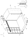
FIG. 1 is a diagram showing a slide rail assembly configured to mount a carried object to a rack according to a first embodiment of the present invention; -
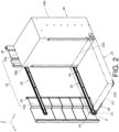
FIG. 2 is a diagram showing the slide rail assembly configured to mount the carried object to the rack according to the first embodiment of the present invention; -
FIG. 3 is an enlarged view of an area A ofFIG. 2 ; -
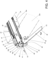
FIG. 4 is a diagram showing a handle configured to unlock a second rail relative to a first rail at a predetermined position according to the first embodiment of the present invention; -
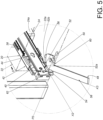
FIG. 5 is a diagram showing the handle configured to interact with a supporting feature to drive the second rail to move away from the predetermined position according to the first embodiment of the present invention; -
FIG. 6 is a diagram showing the second rail being moved away from the predetermined position to disconnect the carried object from another carried object according to the first embodiment of the present invention; -
FIG. 7 is a diagram showing a slide rail assembly configured to mount a carried obj ect to a rack according to a second embodiment of the present invention; -
FIG. 8 is a diagram showing a slide rail assembly configured to mount a carried object to a rack with the carried object being connected to an auxiliary object according to a third embodiment of the present invention; -
FIG. 9 is an exploded view of the slide rail assembly and the carried object with the slide rail assembly being mounted to the rack according to the third embodiment of the present invention; -
FIG. 10 is a diagram showing the carried object being mounted to the rack and located at a predetermined position through the slide rail assembly according to the third embodiment of the present invention; and -
FIG. 11 is a diagram showing a handle configured to interact with a supporting feature to drive the carried object to move away from the predetermined position to disconnect the carried object from the auxiliary object according to the third embodiment of the present invention. - As shown in
FIG. 1 andFIG. 2 , aslide rail assembly 20 is configured to mount a carried object 22 (such as a first carried object or a front carried object) to arack 24 according to a first embodiment of the present invention. In the present embodiment, therack 24 comprises afront post 24a and arear post 24b, but the present invention is not limited thereto. In the present embodiment, therack 24 is further mounted with another carried obj ect 26 (such as a second carried obj ect or a rear carried obj ect) . Specifically, the second carriedobject 26 is configured to be mounted to the rack through theslide rail assembly 20 and/or anotherslide rail assembly 28. The first carriedobject 22 has afront part 22a and arear part 22b, and the second carriedobject 26 has afront part 26a and arear part 26b. - Preferably, the first carried
object 22 has at least one first connecting member 30 (such as a plurality of first connecting members 30), and the second carriedobject 26 has at least one second connecting member 32 (such as a plurality of second connecting members 32). The first connectingmembers 30 and the second connectingmembers 32 can be plugs, sockets or the like (as shown inFIG. 1 ). In the present embodiment, therear part 22b of the first carriedobject 22 is arranged with the first connectingmember 30, and thefront part 26a of the second carriedobject 26 is arranged with the second connectingmember 32, but the present invention is not limited thereto. In other alternative embodiments, the first connectingmember 30 can be arranged at any position on the first carriedobject 22, and the second connectingmember 32 can be arranged at one position on the second carriedobject 26 corresponding to the first connectingmember 30. - Preferably, when the
slide rail assembly 20 is in a retracted state, the first connectingmember 30 on therear part 22b of the first carriedobject 22 and the second connectingmember 32 on thefront part 26a of the second carriedobject 26 are configured be connected with each other (as shown inFIG. 1 ). - Preferably, the
rack 24 comprises a plurality of mounting features, such as a plurality of first mounting features 34 and a plurality of second mounting features 36 configured to mount the twoslide rail assemblies - As shown in
FIGS. 2 and3 , theslide rail assembly 20 comprises afirst rail 38 and asecond rail 40 longitudinally movable relative to thefirst rail 38. Preferably, theslide rail assembly 20 further comprises athird rail 41 movably mounted between thefirst rail 38 and thesecond rail 40. In the present embodiment, the X axis is a longitudinal direction (or a length direction or a moving direction of the slide rail), the Y axis is a transverse direction (or a lateral direction of the slide rail), and the Z axis is a vertical direction (or a height direction of the slide rail) . Thefirst rail 38 is mounted to therack 24. In the present embodiment, thefirst rail 38 is arranged with a supportingframe 42, and thefirst rail 38 is fixedly mounted to therack 24 through the supportingframe 42. Preferably, the supportingframe 42 and thefirst rail 38 are fixedly connected to each other and can be seen as one piece. Furthermore, thefirst rail 38 or the supportingframe 42 has a plurality of corresponding features configured to be mounted to the mounting features 34, 36 of therack 24. On the other hand, thesecond rail 40 has at least onemounting part 44 configured to mount the first carriedobject 22, that is, thesecond rail 40 is configured to carry the first carriedobject 22. - The
slide rail assembly 20 further comprises ahandle 48. When theslide rail assembly 20 is in the retracted state, a locking member (not shown in figures) is configured to lock the second rail 40 (and the first carried object 22) at a first predetermined position P1 (such as a retracted position) relative to thefirst rail 38. For example, the locking member is movably arranged on thesecond rail 40, and the first rail 38 (or the supporting frame 42) comprises a blocking feature (not shown in figures) configured to lock the locking member. Thesecond rail 40 is configured to be temperately locked at a predetermined position through the locking member. Such configuration is well known to those skilled in the art, for simplification, no further illustration is provided. - The
handle 48 is movable relative to thesecond rail 40. In the first embodiment, thehandle 48 is movably mounted to the first carriedobject 22, such that thehandle 48 is movable relative to thesecond rail 40. Furthermore, thehandle 48 is pivotally connected to a bottom part of the first carriedobject 22 through ashaft member 50, but the present invention is not limited thereto. Theshaft member 50 is arranged in a direction substantially identical to the height direction of theslide rail assembly 20. - Preferably, the
slide rail assembly 20 further comprises a supportingfeature 52 arranged on the supportingframe 42 of thefirst rail 38, and the supportingfeature 52 comprises afirst wall 52a (such as a front wall) and asecond wall 52b (such as a rear wall). In the present embodiment, the supportingfeature 52 is a protrusion. In other alternative embodiments, the supportingfeature 52 can be a wall, therefore, the embodiments of the present invention is not limited thereto. On the other hand, thehandle 48 comprises a firstcorresponding section 54 and a secondcorresponding section 56. - Preferably, the
handle 48 further comprises an operatingpart 58 and a workingpart 60. The workingpart 60 is located adjacent to one end of the operatingpart 58, and the firstcorresponding section 54 and the secondcorresponding section 56 are arranged on the workingpart 60 of thehandle 48. In addition, a predetermined space is defined between the firstcorresponding section 54 and the secondcorresponding section 56. When the second rail 40 (and the first carried object 22) is located at the first predetermined position P1, and when thehandle 48 is located at a first operating position K1, the supportingfeature 52 is located in the predetermined space. - Preferably, the
slide rail assembly 20 further comprises an actuatingmember 62 movably mounted to ahousing 64 on thesecond rail 40. The actuatingmember 62 is partially exposed outside thehousing 64, and the actuatingmember 62 is configured to interact with the locking member. - As shown in
FIG. 3 andFIG. 4 , a user can apply a force to the operatingpart 58 of thehandle 48 to move thehandle 48 from the first operating position K1 (as shown inFIG. 3 ) along a predetermined direction J to a second predetermined position K2 (as shown inFIG. 4 ), such that thehandle 48 is configured to unlock thesecond rail 40 to allow the second rail 40 (and the first carried object 22) to move relative to thefirst rail 38 from the first predetermined position P1 along an opening direction D. - Preferably, when the
handle 48 is moved from the first operating position K1 along the predetermined direction J to the second operating position K2, thehandle 48 is configured to drive the actuatingmember 62 to move from an initial position X1 (as shown inFIG. 3 ) to an non-initial position X2 (as shown inFIG. 4 ), such that the actuatingmember 62 further drives the locking member to move in order to unlock thesecond rail 40 relative to thefirst rail 38. - Preferably, when the
handle 48 is moved from the first operating position K1 along the predetermined direction J to the second operating position K2, thehandle 48 is configured to drive the actuatingmember 62 to move from the initial position X1 (as shown inFIG. 3 ) to the non-initial position X2 (as shown inFIG. 4 ) through the firstcorresponding section 54. - Preferably, the first
corresponding section 54 of thehandle 48 and/or the actuatingmember 62 has a guiding surface, such as an inclined surface or an arc surface, such that thehandle 48 can easily drive the actuatingmember 62 to move from the initial position X1 (as shown inFIG. 3 ) to the non-initial position X2 (as shown inFIG. 4 ). In the present embodiment, the firstcorresponding section 54 has afirst guiding surface 66, and the actuatingmember 62 has asecond guiding surface 68, but the present invention is not limited thereto. - Moreover, when the
handle 48 is located at the second operating position K2, the firstcorresponding section 54 of thehandle 48 is moved toward thefirst wall 52a of the supporting feature 52 (as shown inFIG. 4 ). - As shown in
FIG. 4 ,FIG. 5 andFIG. 6 , during a process of thehandle 48 being further moved from the second operating position K2 along the predetermined direction J to a third operating position K3, thehandle 48 continuously contacts the supporting feature 52 (thefirst wall 52a of the supporting feature 52) through the firstcorresponding section 54 to generate an acting force, so that thesecond rail 40 can be moved from the first predetermined position P1 (as shown inFIG. 4 ) along the opening direction D to a second predetermined position P2 (as shown inFIG. 5 andFIG. 6 ) in response to the acting force. Accordingly, the first connectingmember 30 of the first carriedobj ect 22 and the second connectingmember 32 of the second carriedobject 26 are no longer connected with each other and are separated from each other (as shown inFIG. 6 ). - Therefore, during the process of the
handle 48 being moved from the second operating position K2 to the third operating position K3, the firstcorresponding section 54 of thehandle 48 can use the supportingfeature 52 of theslide rail assembly 20 as a supporting point to move thesecond rail 40 from the first predetermined position P1 (as shown inFIG. 4 ) along the opening direction D to the second predetermined position P2 (as shown inFIG. 5 andFIG. 6 ), such that the user can easily disconnect the first connectingmember 30 of the first carriedobject 22 from the second connectingmember 32 of the second carriedobject 26 in order to separate the first carriedobject 22 and the second carriedobject 26 from each other (as shown inFIG. 6 ). -
FIG. 7 is a diagram showing aslide rail assembly 200 according to a second embodiment of the present invention. Moreover, different from theslide rail assembly 20 of the first embodiment having thehandle 48 movably mounted to the first carriedobject 22, theslide rail assembly 200 of the second embodiment has ahandle 202 movably mounted to asecond rail 204. According to such configuration, the second embodiment can achieve substantially identical technical effect as the first embodiment. - Preferably, the
second rail 204 is arranged with anauxiliary member 206, and theauxiliary member 206 comprises afirst part 208 and asecond part 210 bent relative to thefirst part 208. - Preferably, the
first part 208 and thesecond part 210 of theauxiliary member 206 are substantially perpendicularly connected to each other. Thefirst part 208 is connected (such as fixedly connected) to thesecond rail 204, and thehandle 202 is pivotally connected to thesecond part 210 through ashaft member 212. - Preferably, the
second rail 204 is configured carry a carried object (such as a first carried object 214). For example, thesecond rail 204 has at least one mountingpart 216 configured to mount a corresponding mountingpart 218 of the first carriedobject 214. In addition, other configurations of theslide rail assembly 200 of the second embodiment are identical to those of theslide rail assembly 20 of the first embodiment, for simplification, no further illustration is provided. -
FIG. 8 andFIG. 9 are diagrams showing aslide rail assembly 300 applicable to arack 301 and configured to carry a carriedobject 302 according to a third embodiment of the present invention. Theslide rail assembly 300 comprises a supportingfeature 304. Ahandle 306 is movably mounted to the carriedobject 302. Different from thehandle 48 of the first embodiment being pivotally connected to the bottom part of the carried object, thehandle 306 of the third embodiment is pivotally connected to a lateral part of the carriedobj ect 302 through ashaft member 308 . In addition, theshaft member 308 is arranged in a direction substantially identical to a transverse direction (or a lateral direction) of theslide rail assembly 300. Preferably, thehandle 306 comprises a firstcorresponding section 310. - As shown in
FIG. 10 andFIG. 11 , therack 301 has afront end 301a and arear end 301b, and anauxiliary object 309 is arranged adjacent to therear end 301b of therack 301. When the carriedobject 302 is located at a first predetermined position P1' (such as a retracted position as shown inFIG. 10 ), a first connecting member of the carried object 302 (arear part 302b of the carried obj ect 302) and a second connecting member of the auxiliary obj ect 309 (afront part 309a of the auxiliary obj ect 309) can be connected with each other. (such connection configuration between the first connecting member and the second connecting member can refer toFIG. 1 , for simplification, no further illustration is provided.) - During a process of the
handle 306 being moved from one operating position K1' (as shown inFIG. 10 ) along a predetermined direction J' to another operating position K2' (as shown inFIG. 11 ), thehandle 306 continuously contacts the supportingfeature 304 through the firstcorresponding section 310 to generate an acting force, such that the carriedobject 302 can be moved from the first predetermined position P1' (as shown inFIG. 10 ) along the opening direction D to a second predetermined position P2' (as shown inFIG. 11 ) in response to the acting force. Accordingly, the first connecting member of the carriedobject 302 and the second connecting member of theauxiliary member 309 are no longer connected with each other and are separated from each other (such disconnection configuration between the first connecting member and the second connecting member can refer toFIG. 6 , for simplification, no further illustration is provided.) - Preferably, the
slide rail assembly 300 comprises afirst rail 312, and thefirst rail 312 is fixedly mounted to therack 301 through a supportingframe 314. Preferably, the supportingframe 314 and thefirst rail 312 are fixedly connected to each other and can be seen as one piece. Furthermore, therack 301 comprises a plurality of mountingfeatures 311 configured to mount the slide rail assembly 300 (the supportingframe 314 of the slide rail assembly 300). On the other hand, an upper part of the carriedobject 302 is configured to be mounted to therack 301 through another slide rail assembly (not shown in the figures), such that the carriedobject 302 is longitudinally slidable relative to therack 301. - Preferably, the supporting
feature 304 is arranged on one of the supportingframe 314 and thefirst rail 312. In the present embodiment, the supportingfeature 304 is arranged on thefirst rail 312. - Preferably, one of the supporting
frame 314 and thefirst rail 312 is arranged with a supportingpart 318, and the supportingpart 318 has a first predetermined longitudinal length. In the present embodiment, thefirst rail 312 is arranged with the supportingpart 318, and the carriedobject 302 is arranged with a supportingmember 320 configured to be supported by the supportingpart 318. In the present embodiment, the supportingmember 320 is a protrusion or cylinder, but the present invention is not limited thereto. - Preferably, one of the supporting
frame 314 and thefirst rail 312 is further arranged with anextension wall 322, and theextension wall 322 has a second predetermined longitudinal length shorter than the first predetermined longitudinal length of the supportingpart 318. In the present embodiment, thefirst rail 312 is arranged with theextension wall 322. An accommodating space S' is defined between theextension wall 322 and the supportingpart 318, and configured to accommodate the supportingmember 320 of the carriedobject 302. - Preferably, when the carried
object 302 is located at the first predetermined position P1', the supportingmember 320 can be accommodated in the accommodating space S', and the supportingmember 320 is configured to be blocked by a wall at an edge of the accommodating space S', in order to limit movement of the carried object 302 (as shown inFIG. 10 ). - Preferably, the
handle 306 further comprises a secondcorresponding section 324. In addition, a predetermined space is defined between the firstcorresponding section 310 and the secondcorresponding section 324. When the carriedobject 302 is located at the first predetermined position P1' and when thehandle 306 is located at the operating position K1' (as shown inFIG. 10 ), the supportingfeature 304 is located in the predetermined space. - Preferably, the
handle 306 further comprises anoperating part 326 and a workingpart 328. The workingpart 328 is located adjacent to one end of the operatingpart 326, and the firstcorresponding section 310 and the secondcorresponding section 324 are arranged on the workingpart 328 of thehandle 306. - Therefore, the slide rail assembly according to the embodiments of the present invention has the following technical features:
- 1. The
handle 48 is configured to unlock thesecond rail 40 relative to thefirst rail 38 at a first predetermined position P1. - 2. The supporting feature (52, 304) on the slide rail assembly (20, 200, 300) can be used as a supporting point to assist the handle (48, 202, 306) in driving the second rail (40, 204) or the carried object (22, 214, 302) to move from the first predetermined position (P1, P1') to the second predetermined position (P2, P2') .
- 3. The handle (48, 306) is movably mounted to the carried object (22, 302); or the
handle 202 is movably mounted to the slide rail.
Claims (15)
- A slide rail assembly (20, 200), comprising:a first rail (38);a second rail (40, 204) movable relative to the first rail (38); anda handle (48, 202) movable relative to the second rail (40, 204) ;wherein when the handle (48, 202) is moved from a first operating position along a predetermined direction to a second operating position, the handle (48, 202) is configured to unlock the second rail (40, 204) relative to the first rail (38) at a first predetermined position.
- The slide rail assembly of claim 1, further characterized by an actuating member (62); wherein when the handle (48, 202) is moved from the first operating position along the predetermined direction to the second operating position, the handle (48, 202) is configured to drive the actuating member (62) to unlock the second rail (40, 204) relative to the first rail (38) at the first predetermined position.
- The slide rail assembly of claim 1 or 2, characterized in that the second rail (40) is configured to carry a carried object (22), and the handle (48) is movably mounted to the carried object (22).
- The slide rail assembly of any of claims 1-3, further characterized by a supporting feature (52) arranged on the first rail (38), wherein the handle (48, 202) comprises a first corresponding section (54) ; wherein during a process of the handle (48, 202) being moved from the second operating position along the predetermined direction to a third operating position, the handle (48, 202) is configured to continuously contact the supporting feature (52) through the first corresponding section (54), in order to move the second rail (40, 204) from the first predetermined position to a second predetermined position; wherein the handle (48, 202) further comprises a second corresponding section (56), and a predetermined space is defined between the second corresponding section (56) and the first corresponding section (54) ; wherein when the second rail (40) is located at the first predetermined position and when the handle (48, 202) is located at the first operating position, the supporting feature (52) is located in the predetermined space.
- The slide rail assembly of claim 3, characterized in that the first rail (38) is mounted to a rack (24) through a supporting frame (42); wherein the supporting feature (52) is arranged on the supporting frame (42); wherein the handle (48) is movable relative to the second rail (40) in a pivotal manner.
- A slide rail system, comprising:a carried object (22, 302);a slide rail assembly (20, 300) configured to carry the carried object (22, 302), the slide rail assembly (20, 300) comprising a supporting feature (52, 304); anda handle (48, 306) movably mounted to the carried object (22, 302) ;wherein during a process of the handle (48, 306) being moved from one operating position to another operating position, the handle (48, 306) is configured to continuously contact the supporting feature (52, 304), in order to move the carried object (22, 302) from a first predetermined position to a second predetermined position.
- The slide rail system of claim 6, characterized in that the slide rail assembly (20, 300) further comprises a first rail (38, 312), and the first rail (38, 312) is fixedly mounted to a rack (24, 301); wherein the supporting feature (52, 304) is arranged on the first rail (38, 312).
- The slide rail system of claim 7, characterized in that the first rail (312) is arranged with a supporting part (318), and the carried object (302) is arranged with a supporting member (320) configured to be supported by the supporting part (318); wherein the first rail (312) is further arranged with an extension wall (322), and an accommodating space is defined between the extension wall (322) and the supporting part (318).
- The slide rail system of claim 8, characterized in that when the carried object (302) is located at the first predetermined position, the supporting member (320) of the carried object (302) is configured to be accommodated in the accommodating space.
- A slide rail assembly (20, 200), comprising:a first rail (38);a second rail (40, 204) movable relative to the first rail (38); anda handle (48, 202) movably mounted to the second rail (40, 204) ;wherein a supporting feature (52) is arranged on the first rail (38), and the handle (48, 202) comprises a first corresponding section (54) ; wherein when the handle (48, 202) is moved from one operating position to another operating position, the handle (48, 202) is configured to contact the supporting feature (52) through the first corresponding section (54), in order to move the second rail (40, 204) from a first predetermined position to a second predetermined position.
- The slide rail assembly of claim 10, characterized in that the handle (48, 202) further comprises a second corresponding section (56), and a predetermined space is defined between the second corresponding section (56) and the first corresponding section (54); wherein when the second rail (40, 204) is located at the first predetermined position and when the handle (48, 202) is located at the operating position, the supporting feature (52) is located in the predetermined space.
- The slide rail assembly of claim 10 or 11, characterized in that a supporting frame (42) is fixed to the first rail (38), and the first rail (38) is mounted to a rack (24) through the supporting frame (42).
- The slide rail assembly of claim 12, characterized in that the supporting feature (52) is arranged on the supporting frame (42) .
- The slide rail assembly of any of claims 10-13, characterized in that the first predetermined position is a retracted position.
- The slide rail assembly of any of claims 10-14, characterized in that the handle (202) is pivotally connected to the second rail (204) .
Applications Claiming Priority (1)
| Application Number | Priority Date | Filing Date | Title |
|---|---|---|---|
| TW112101922A TWI829509B (en) | 2023-01-13 | 2023-01-13 | Slide rail assembly |
Publications (1)
| Publication Number | Publication Date |
|---|---|
| EP4401520A1 true EP4401520A1 (en) | 2024-07-17 |
Family
ID=88093691
Family Applications (1)
| Application Number | Title | Priority Date | Filing Date |
|---|---|---|---|
| EP23197877.6A Pending EP4401520A1 (en) | 2023-01-13 | 2023-09-18 | Slide rail assembly |
Country Status (4)
| Country | Link |
|---|---|
| US (1) | US20240240669A1 (en) |
| EP (1) | EP4401520A1 (en) |
| JP (2) | JP2024100665A (en) |
| TW (1) | TWI829509B (en) |
Families Citing this family (2)
| Publication number | Priority date | Publication date | Assignee | Title |
|---|---|---|---|---|
| TWI847902B (en) * | 2023-10-30 | 2024-07-01 | 川湖科技股份有限公司 | Slide rail assembly |
| TWI847910B (en) * | 2023-11-09 | 2024-07-01 | 川湖科技股份有限公司 | Slide rail assembly |
Citations (3)
| Publication number | Priority date | Publication date | Assignee | Title |
|---|---|---|---|---|
| US20090294393A1 (en) * | 2008-05-28 | 2009-12-03 | King Slide Works Co., Ltd. | Slide assembly for a rack |
| US20110169389A1 (en) * | 2010-03-19 | 2011-07-14 | Austin Hardware & Supply, Inc. | Drawer release |
| US20220369478A1 (en) | 2021-05-14 | 2022-11-17 | Wiwynn Corporation | Handle module, server, and server system |
Family Cites Families (28)
| Publication number | Priority date | Publication date | Assignee | Title |
|---|---|---|---|---|
| JPH0165185U (en) * | 1987-10-21 | 1989-04-26 | ||
| US5669512A (en) * | 1995-01-05 | 1997-09-23 | Hewlett-Packard Co. | Inject-eject system for rack mounted plug-in modules |
| DE50200465D1 (en) * | 2002-02-07 | 2004-06-24 | Schroff Gmbh | Device for inserting and removing a plug-in module |
| US6883884B2 (en) * | 2002-09-25 | 2005-04-26 | King Slide Works Co., Ltd. | Latch assembly for a track device |
| US7364244B2 (en) * | 2003-05-14 | 2008-04-29 | Hewlett-Packard Development Company | User-controllable latching carrier rail system |
| US7125272B1 (en) * | 2005-12-29 | 2006-10-24 | Super Micro Computer, Inc. | Modular case handle positioning device |
| KR101621556B1 (en) * | 2009-12-22 | 2016-05-16 | 엘지전자 주식회사 | Refrigerator |
| US8403432B2 (en) * | 2010-09-24 | 2013-03-26 | King Slide Works Co., Ltd. | Latch and release device for slide assembly |
| US8416563B2 (en) * | 2011-01-14 | 2013-04-09 | Chicony Power Technology Co., Ltd. | Swapping apparatus of electronic device |
| US8611103B2 (en) * | 2011-10-27 | 2013-12-17 | Cisco Technology, Inc. | Latching injector/ejector |
| US9609778B1 (en) * | 2015-10-05 | 2017-03-28 | Hewlett Packard Enterprise Development Lp | Server having a latch |
| US9872413B2 (en) * | 2015-10-23 | 2018-01-16 | Dell Products, L.P. | Multi-function handle for Information Handling System (IHS) chassis |
| US10111356B2 (en) * | 2016-03-31 | 2018-10-23 | Oracle International Corporation | System for electrical connection of printed circuit boards and backplanes in server enclosure |
| TWI594711B (en) * | 2016-05-31 | 2017-08-11 | 川湖科技股份有限公司 | Slide rail device |
| TWI611747B (en) * | 2016-10-12 | 2018-01-11 | 川湖科技股份有限公司 | Bracket device |
| US10136547B1 (en) * | 2017-06-23 | 2018-11-20 | Alcatel Lucent | Retracting latch |
| TWI642385B (en) * | 2017-08-31 | 2018-12-01 | 川湖科技股份有限公司 | Slide rail assembly and slide rail mechanism thereof |
| US10383248B1 (en) * | 2018-06-15 | 2019-08-13 | Super Micro Computer Inc. | Locking mechanism and server having the same |
| US10443271B1 (en) * | 2018-10-29 | 2019-10-15 | The Cornwell Quality Tools Company | Drawer latch system |
| TWI679930B (en) * | 2019-02-01 | 2019-12-11 | 勤誠興業股份有限公司 | Server device and its latch mechanism |
| US10568230B1 (en) * | 2019-04-11 | 2020-02-18 | Super Micro Computer Inc. | Server rack with ultra-long chassis |
| US10939573B1 (en) * | 2019-08-28 | 2021-03-02 | Dell Products, L.P. | Electronic module carrier for an information handling system |
| US11197389B2 (en) * | 2020-04-06 | 2021-12-07 | Super Micro Computer Inc. | Server chassis |
| US11382233B2 (en) * | 2020-10-30 | 2022-07-05 | Quanta Computer Inc. | Removable lever for inserting and removing a tray from a chassis module of a server rack |
| US11337332B1 (en) * | 2020-10-30 | 2022-05-17 | ZT Group Intl, Inc. | Latch with auto-close |
| TWM612172U (en) * | 2020-12-22 | 2021-05-21 | 廣達電腦股份有限公司 | Removable lever for inserting and removing computer equipment from a chassis module of a server rack |
| CN113597188B (en) * | 2021-08-31 | 2024-05-28 | 南京莱斯电子设备有限公司 | A helping hand plug ware that is used for inside locking function that has of electronic machine case |
| TWI806513B (en) * | 2022-03-23 | 2023-06-21 | 緯創資通股份有限公司 | Casing assembly and electronic device including the same |
-
2023
- 2023-01-13 TW TW112101922A patent/TWI829509B/en active
- 2023-07-05 US US18/346,978 patent/US20240240669A1/en active Pending
- 2023-09-05 JP JP2023143308A patent/JP2024100665A/en active Pending
- 2023-09-18 EP EP23197877.6A patent/EP4401520A1/en active Pending
-
2025
- 2025-12-25 JP JP2025281295A patent/JP2026053602A/en active Pending
Patent Citations (3)
| Publication number | Priority date | Publication date | Assignee | Title |
|---|---|---|---|---|
| US20090294393A1 (en) * | 2008-05-28 | 2009-12-03 | King Slide Works Co., Ltd. | Slide assembly for a rack |
| US20110169389A1 (en) * | 2010-03-19 | 2011-07-14 | Austin Hardware & Supply, Inc. | Drawer release |
| US20220369478A1 (en) | 2021-05-14 | 2022-11-17 | Wiwynn Corporation | Handle module, server, and server system |
Also Published As
| Publication number | Publication date |
|---|---|
| TWI829509B (en) | 2024-01-11 |
| TW202429975A (en) | 2024-07-16 |
| US20240240669A1 (en) | 2024-07-18 |
| JP2024100665A (en) | 2024-07-26 |
| JP2026053602A (en) | 2026-03-25 |
Similar Documents
| Publication | Publication Date | Title |
|---|---|---|
| EP3750445B1 (en) | Slide rail assembly and operation method thereof | |
| EP3679833B1 (en) | Slide rail assembly | |
| US20240240669A1 (en) | Slide Rail Assembly | |
| EP3821762B1 (en) | Slide rail assembly | |
| EP3195760A1 (en) | Slide rail assembly and operation method thereof | |
| EP3777610B1 (en) | Slide rail assembly | |
| JP6994078B2 (en) | Slide rail assembly | |
| EP3609304B1 (en) | Slide rail mechanism and bracket device thereof | |
| EP3644695A1 (en) | Slide rail assembly | |
| EP3833169B1 (en) | Slide rail assembly | |
| EP4548808B1 (en) | Slide rail assembly | |
| EP4327696A1 (en) | Slide rail assembly | |
| EP4501174B1 (en) | Slide rail assembly | |
| EP3307037B1 (en) | Slide rail assembly | |
| EP4475642B1 (en) | Slide rail assembly | |
| EP3979775A1 (en) | Slide rail assembly | |
| EP4327697A1 (en) | Slide rail assembly and slide rail kit | |
| EP3073811B1 (en) | Slide rail assembly | |
| EP4629760A1 (en) | Slide rail assembly | |
| CN117528991B (en) | Box lock assembly of LED display device and LED display device | |
| CN117218970A (en) | LED display device | |
| US20250089891A1 (en) | Slide rail assembly | |
| CN118368843A (en) | Sliding rail assembly | |
| CN112754197A (en) | Sliding rail assembly | |
| CN113120780B (en) | Rotary platform and working machine |
Legal Events
| Date | Code | Title | Description |
|---|---|---|---|
| PUAI | Public reference made under article 153(3) epc to a published international application that has entered the european phase |
Free format text: ORIGINAL CODE: 0009012 |
|
| STAA | Information on the status of an ep patent application or granted ep patent |
Free format text: STATUS: THE APPLICATION HAS BEEN PUBLISHED |
|
| AK | Designated contracting states |
Kind code of ref document: A1 Designated state(s): AL AT BE BG CH CY CZ DE DK EE ES FI FR GB GR HR HU IE IS IT LI LT LU LV MC ME MK MT NL NO PL PT RO RS SE SI SK SM TR |
|
| STAA | Information on the status of an ep patent application or granted ep patent |
Free format text: STATUS: REQUEST FOR EXAMINATION WAS MADE |
|
| 17P | Request for examination filed |
Effective date: 20240822 |
|
| RBV | Designated contracting states (corrected) |
Designated state(s): AL AT BE BG CH CY CZ DE DK EE ES FI FR GB GR HR HU IE IS IT LI LT LU LV MC ME MK MT NL NO PL PT RO RS SE SI SK SM TR |