EP4401326A1 - Communication system for outboard motor drive - Google Patents
Communication system for outboard motor drive Download PDFInfo
- Publication number
- EP4401326A1 EP4401326A1 EP23214252.1A EP23214252A EP4401326A1 EP 4401326 A1 EP4401326 A1 EP 4401326A1 EP 23214252 A EP23214252 A EP 23214252A EP 4401326 A1 EP4401326 A1 EP 4401326A1
- Authority
- EP
- European Patent Office
- Prior art keywords
- line
- outboard motor
- turn
- bus line
- hull
- Prior art date
- Legal status (The legal status is an assumption and is not a legal conclusion. Google has not performed a legal analysis and makes no representation as to the accuracy of the status listed.)
- Pending
Links
Images


Classifications
-
- H—ELECTRICITY
- H04—ELECTRIC COMMUNICATION TECHNIQUE
- H04B—TRANSMISSION
- H04B3/00—Line transmission systems
-
- B—PERFORMING OPERATIONS; TRANSPORTING
- B63—SHIPS OR OTHER WATERBORNE VESSELS; RELATED EQUIPMENT
- B63H—MARINE PROPULSION OR STEERING
- B63H21/00—Use of propulsion power plant or units on vessels
- B63H21/21—Control means for engine or transmission, specially adapted for use on marine vessels
-
- B—PERFORMING OPERATIONS; TRANSPORTING
- B63—SHIPS OR OTHER WATERBORNE VESSELS; RELATED EQUIPMENT
- B63B—SHIPS OR OTHER WATERBORNE VESSELS; EQUIPMENT FOR SHIPPING
- B63B79/00—Monitoring properties or operating parameters of vessels in operation
- B63B79/40—Monitoring properties or operating parameters of vessels in operation for controlling the operation of vessels, e.g. monitoring their speed, routing or maintenance schedules
-
- F—MECHANICAL ENGINEERING; LIGHTING; HEATING; WEAPONS; BLASTING
- F02—COMBUSTION ENGINES; HOT-GAS OR COMBUSTION-PRODUCT ENGINE PLANTS
- F02D—CONTROLLING COMBUSTION ENGINES
- F02D41/00—Electrical control of supply of combustible mixture or its constituents
- F02D41/24—Electrical control of supply of combustible mixture or its constituents characterised by the use of digital means
- F02D41/26—Electrical control of supply of combustible mixture or its constituents characterised by the use of digital means using computer, e.g. microprocessor
- F02D41/266—Electrical control of supply of combustible mixture or its constituents characterised by the use of digital means using computer, e.g. microprocessor the computer being backed-up or assisted by another circuit, e.g. analogue
-
- B—PERFORMING OPERATIONS; TRANSPORTING
- B63—SHIPS OR OTHER WATERBORNE VESSELS; RELATED EQUIPMENT
- B63H—MARINE PROPULSION OR STEERING
- B63H20/00—Outboard propulsion units, e.g. outboard motors or Z-drives; Arrangements thereof on vessels
-
- B—PERFORMING OPERATIONS; TRANSPORTING
- B63—SHIPS OR OTHER WATERBORNE VESSELS; RELATED EQUIPMENT
- B63H—MARINE PROPULSION OR STEERING
- B63H21/00—Use of propulsion power plant or units on vessels
- B63H21/21—Control means for engine or transmission, specially adapted for use on marine vessels
- B63H2021/216—Control means for engine or transmission, specially adapted for use on marine vessels using electric control means
Definitions
- the present invention relates to a communication system for outboard motor drive.
- a communication system for outboard motor drive including a bus line that includes two signal lines to transmit data between an in-hull maneuvering controller in a hull and an outboard motor using a voltage difference between the two signal lines is known in general.
- Such a communication system for outboard motor drive is disclosed in JP 2007-309294 A , for example.
- JP 2007-309294 A discloses an outboard motor operation system for a marine vessel including a CAN cable that includes a high-level signal line and a low-level signal line.
- the outboard motor operation system further includes one outboard motor and a remote control ECU in a hull, and transmits data between the outboard motor and the remote control ECU via the CAN cable.
- a first end of the CAN cable is located in the hull, and a terminating resistor is provided at the first end to reduce noise that is a reflected wave.
- a second end of the CAN cable is located inside the outboard motor, and a terminating resistor is provided at the second end to reduce noise that is a reflected wave.
- a system to operate a plurality of outboard motors may be constructed using outboard motors including terminating resistors as described above.
- an unused (wasted) terminating resistor is generated among the terminating resistors located in the outboard motors, and thus an improvement is desired.
- a communication system for outboard motor drive includes a main bus line including two signal lines configured to transmit data using a voltage difference between the two signal lines, and configured to communicate with an outboard motor, an in-hull maneuvering controller provided at a first end of the main bus line in a hull, a first terminating resistor provided in the in-hull maneuvering controller and configured to electrically connect the two signal lines, and a second terminating resistor provided at a second end of the main bus line and configured to electrically connect the two signal lines.
- the main bus line is connected to the second terminating resistor provided in the hull by passing through the outboard motor from a side of the first terminating resistor and making a U-turn.
- a communication system for outboard motor drive includes the first terminating resistor in the in-hull maneuvering controller to electrically connect the two signal lines, and the second terminating resistor at the second end of the main bus line to electrically connect the two signal lines, and the main bus line is connected to the second terminating resistor in the hull by passing through the outboard motor from the side of the first terminating resistor and making a U-turn. Accordingly, the main bus line makes a U-turn, and thus the main bus line is returned into the hull after passing through the outboard motor such that both ends of the main bus line are located in the hull.
- the two terminating resistors are located in the hull such that the terminating resistors are removed from inside the outboard motor.
- the number of terminating resistors does not vary depending on the number of outboard motors unlike the conventional case, and the number of terminating resistors in the communication system is minimized. Consequently, generation of an unused terminating resistor is prevented.
- a communication system for outboard motor drive preferably further includes an in-outboard motor controller configured or programmed to control driving of the outboard motor, and a stub line connected to the in-outboard motor controller.
- the main bus line preferably includes a U-turn line that is a folded portion configured to make a U-turn outside the hull and is connected to the in-outboard motor controller via the stub line. Accordingly, the stub line and the U-turn line facilitate communication between the in-hull maneuvering controller and the in-outboard motor controller, and the main bus line is easily returned into the hull from inside the outboard motor.
- the main bus line preferably includes a first end-side line connected to the first terminating resistor in the hull, and a second end-side line connected to the second terminating resistor in the hull, the first end-side line is preferably connected to the second end-side line by the U-turn line configured to make a U-turn outside the hull, and the U-turn line is preferably configured to be attachable to and detachable from the first end-side line and the second end-side line. Accordingly, the U-turn line is attachable to and detachable from the first end-side line and the second end-side line, and thus the lines are easily connected to each other.
- the outboard motor preferably includes a first outboard motor including a first in-outboard motor controller as the in-outboard motor controller, and a second outboard motor including a second in-outboard motor controller as the in-outboard motor controller.
- the stub line preferably includes a first stub line configured to connect the main bus line to the first in-outboard motor controller, and a second stub line configured to connect the main bus line to the second in-outboard motor controller.
- the U-turn line preferably includes a first U-turn line connected to the first in-outboard motor controller via the first stub line and connected to the first end-side line, and a second U-turn line connected to the second in-outboard motor controller via the second stub line and connected to the second end-side line.
- the main bus line preferably further includes a connection line configured to connect the first U-turn line to the second U-turn line. Accordingly, the first stub line, the second stub line, the first U-turn line, and the second U-turn line facilitate communication between the in-hull maneuvering controller, the first in-outboard motor controller, and the second in-outboard motor controller, and the main bus line is easily returned into the hull from inside the outboard motor.
- the stub line includes the first stub line and the second stub line
- the U-turn line includes the first U-turn line and the second U-turn line
- the first U-turn line and the first stub line are preferably located inside the first outboard motor
- the second U-turn line and the second stub line are preferably located inside the second outboard motor. Accordingly, the first U-turn line and the first stub line are housed in the first outboard motor
- the second U-turn line and the second stub line are housed in the second outboard motor, and thus complex wiring outside the outboard motor is reduced or prevented.
- the stub line includes the first stub line and the second stub line
- the U-turn line includes the first U-turn line and the second U-turn line
- the first U-turn line and the second U-turn line each of which is a portion of the main bus line, preferably have the same structure as each other.
- the first U-turn line in the first outboard motor and the second U-turn line in the second outboard motor have the same structure as each other, and thus even when the positions of the first outboard motor and the second outboard motor are swapped or the positions of the first U-turn line and the second U-turn line are swapped, the in-hull maneuvering controller, the first in-outboard motor controller, and the second in-outboard motor controller are communicably connected to each other.
- a communication system for outboard motor drive in which the first end-side line is connected to the second end-side line by the U-turn line preferably further includes a first connector configured to detachably connect the U-turn line to the first end-side line and the second end-side line. Accordingly, the U-turn line is easily connected to the first end-side line by the first connector.
- the first connector is preferably integral and unitary with the outboard motor. Accordingly, the number of divisible components in the system is reduced such that the system structure is simplified.
- the first end-side line preferably includes a first line provided closer to the first terminating resistor, and a second line provided closer to the first connector
- the communication system for outboard motor drive preferably further comprises a second connector configured to detachably connect the first line to the second line in the hull. Accordingly, the first end-side line is shortened by being divided into two portions, the first line and the second line, and thus the first end-side line is easily routed without tangling. Furthermore, the first line is easily connected to the second line by the second connector.
- the two signal lines of the main bus line preferably include a high bus line configured to be at a high voltage during data transmission, and a low bus line configured to be at a low voltage during data transmission, and the main bus line is preferably based on a CAN communication standard and is preferably configured to transmit data based on a voltage difference between the high bus line and the low bus line. Accordingly, in the communication system for outboard motor drive based on the CAN communication standard, generation of an unused termination resistor is prevented.
- the high bus line and the low bus line of the main bus line are preferably twisted together and are preferably configured to connect the first terminating resistor to the second terminating resistor. Accordingly, the high bus line and the low bus line are a so-called twisted cable, and thus noise during data transmission is reduced.
- the structure of a marine vessel 100 including a communication system 102 for outboard motor drive is now described with reference to FIGS. 1 to 4 .
- the communication system 102 for outboard motor drive is an example of a "communication system for propulsion device drive”.
- the marine vessel 100 includes a hull 101 and the communication system 102 for outboard motor drive mounted on the hull 101.
- the communication system 102 for outboard motor drive includes an outboard motor 1 on the hull 101.
- the outboard motor 1 is an example of a "marine propulsion device".
- the outboard motor 1 is attached to a transom of the hull 101.
- the outboard motor 1 includes a first outboard motor 10 and a second outboard motor 11.
- the first outboard motor 10 and the second outboard motor 11 are aligned side by side along a right-left direction of the hull 101.
- the first outboard motor 10 and the second outboard motor 11 have the same structure as each other. Therefore, the first outboard motor 10 is described below.
- the first outboard motor 10 shown in FIG. 2 is an electric propulsion device in which a propeller P is driven by an electric motor.
- the first outboard motor 10 is a duct-driven propulsion device in which the electric motor is integral and unitary with a duct D and the propeller P.
- the first outboard motor 10 rotates the duct D and the propeller P in the right-left direction by a steering mechanism (not shown) about a central axis a.
- the propeller P rotates about a central axis ⁇ .
- Each of the first outboard motor 10 and the second outboard motor 11 includes an in-outboard motor controller C that controls driving of the electric motor, for example, that is a drive source of the propeller P.
- the communication system 102 for outboard motor drive includes an in-hull maneuvering controller 102a, a first terminating resistor 2a, a second terminating resistor 2b, a main bus line 3, a stub line 4 connected to the in-hull maneuvering controller 102a, first connectors 5a and 5b, and a second connector 6.
- the main bus line 3 includes two signal lines 30 to transmit data using a voltage difference between the two signal lines 30.
- the main bus line 3 is provided to communicate with the outboard motor 1 (the first outboard motor 10 and the second outboard motor 11).
- the two signal lines 30 of the main bus line 3 include a high bus line 30a that is at a high voltage during data transmission, and a low bus line 30b that is at a low voltage during data transmission.
- the main bus line 3 is based on a CAN (controller area network) communication standard and transmits data based on a voltage difference between the high bus line 30a and the low bus line 30b.
- the communication system 102 for outboard motor drive employs a so-called two-wire differential voltage system.
- the two-wire differential voltage system the same noise is generated on the high bus line 30a and the low bus line 30b at the same time, and thus the noise does not affect the voltage difference (transmitted data) between the high bus line 30a and the low bus line 30b. Therefore, the two-wire differential voltage system is a communication system with high noise resistance.
- the high bus line 30a and the low bus line 30b of the main bus line 3 have substantially the same lengths.
- the high bus line 30a and the low bus line 30b of the main bus line 3 are provided in parallel to each other.
- the high bus line 30a and the low bus line 30b of the main bus line 3 are twisted together and connect the first terminating resistor 2a to the second terminating resistor 2b.
- the in-hull maneuvering controller 102a is located at a first end 3a of the main bus line 3 in the hull 101.
- the in-hull maneuvering controller 102a controls driving of the outboard motor 1 (the first outboard motor 10 and the second outboard motor 11).
- the in-hull maneuvering controller 102a includes a CPU and a memory.
- the in-hull maneuvering controller 102a includes a so-called boat control unit to adjust driving of the first outboard motor 10 and the second outboard motor 11 to perform automatic marine vessel maneuvering.
- the in-hull maneuvering controller may include a master remote control ECU of remote control ECUs provided one for each outboard motor, for example.
- the in-outboard motor controller C includes a first in-outboard motor controller C1 and a second in-outboard motor controller C2.
- the first outboard motor 10 includes the first in-outboard motor controller C1.
- the second outboard motor 11 includes the second in-outboard motor controller C2.
- the first in-outboard motor controller C1 and the second in-outboard motor controller C2 have the same structure as each other.
- Each of the first in-outboard motor controller C1 and the second in-outboard motor controller C2 includes a CPU and a memory.
- the first terminating resistor 2a is provided in the in-hull maneuvering controller 102a located at the first end 3a of the main bus line 3.
- the first terminating resistor 2a electrically connects the two signal lines 30 (the high bus line 30a and the low bus line 30b).
- the first terminating resistor 2a reduces or prevents signal reflection generated at terminations of the high bus line 30a and the low bus line 30b (the first end 3a of the main bus line 3) during data transmission. In short, the first terminating resistor 2a reduces or prevents noise by consuming reflected energy that causes noise.
- the second terminating resistor 2b is provided at a second end 3b of the main bus line 3.
- the second terminating resistor 2b electrically connects the two signal lines 30 (the high bus line 30a and the low bus line 30b).
- the second terminating resistor 2b reduces or prevents signal reflection generated at terminations of the high bus line 30a and the low bus line 30b (the second end 3b of the main bus line 3) during data transmission. In short, the second terminating resistor 2b reduces or prevents noise by consuming reflected energy that causes noise.
- the communication system 102 for outboard motor drive includes only two terminating resistors, the first terminating resistor 2a and the second terminating resistor 2b.
- the main bus line 3 is connected to the second terminating resistor 2b located in the hull 101 by passing through the outboard motor 1 from the first terminating resistor 2a side and making a U-turn.
- the main bus line 3 includes a U-turn line 33 that is a folded portion that makes a U-turn outside the hull 101 and is connected to the in-outboard motor controller C via the stub line 4.
- the main bus line 3 includes a first end-side line 31 connected to the first terminating resistor 2a in the hull 101, and a second end-side line 32 connected to the second terminating resistor 2b in the hull 101.
- the U-turn line 33 includes a first U-turn line 33a and a second U-turn line 33b.
- the first end-side line 31 is connected to the second end-side line 32 by the U-turn line 33 that makes a U-turn outside the hull 101.
- the outside of the hull 101 in which the U-turn line 33 makes a U-turn corresponds to the inside of the first outboard motor 10 and the inside of the second outboard motor 11.
- the stub line 4 includes a first stub line 4a and a second stub line 4b.
- the first stub line 4a connects the main bus line 3 to the first in-outboard motor controller C1.
- the second stub line 4b connects the main bus line 3 to the second in-outboard motor controller C2.
- the first U-turn line 33a is connected to the first in-outboard motor controller C1 via the first stub line 4a, and is connected to the first end-side line 31.
- the second U-turn line 33b is connected to the second in-outboard motor controller C2 via the second stub line 4b, and is connected to the second end-side line 32.
- the first U-turn line 33a and the second U-turn line 33b, each of which is a portion of the main bus line 3, have the same structure as each other.
- the main bus line 3 includes a connection line 34.
- the connection line 34 connects the first U-turn line 33a to the second U-turn line 33b outside the outboard motor 1 (between the first outboard motor 10 and the second outboard motor 11).
- Each of the first end-side line 31, the second end-side line 32, the first U-turn line 33a, the second U-turn line 33b, and the connection line 34 includes the high bus line 30a and the low bus line 30b in parallel to each other.
- the U-turn line 33 of the main bus line 3 is attachable to and detachable from the first end-side line 31 and the second end-side line 32.
- the first connectors 5a and 5b are used to attach and detach the U-turn line 33 to and from the first end-side line 31 and the second end-side line 32.
- the first U-turn line 33a and the first stub line 4a are located inside the first outboard motor 10.
- the second U-turn line 33b and the second stub line 4b are located inside the second outboard motor 11.
- the first connector 5a is integral and unitary with the first outboard motor 10.
- the first connector 5b is integral and unitary with the second outboard motor 11.
- the first connectors 5a and 5b detachably connect the U-turn line 33 to the first end-side line 31 and the second end-side line 32.
- the first connector 5a connects the first U-turn line 33a to the first end-side line 31.
- the first U-turn line 33a and the first end-side line 31 are electrically connected to each other via the first connector 5a.
- the first connector 5b connects the second U-turn line 33b to the second end-side line 32.
- the second U-turn line 33b and the second end-side line 32 are electrically connected to each other via the first connector 5b.
- the first connector 5a connects the first U-turn line 33a to a first end of the connection line 34.
- the first U-turn line 33a and the connection line 34 are electrically connected to each other via the first connector 5a.
- the first connector 5b connects the second U-turn line 33b to a second end of the connection line 34.
- the second U-turn line 33b and the connection line 34 are electrically connected to each other via the first connector 5b.
- first end-side line 31 and the second end-side line 32 are electrically connected to each other via the first connector 5a, the first U-turn line 33a, the connection line 34, the first connector 5b, and the second U-turn line 33b.
- the first end-side line 31 includes a first line 31a closer to the first terminating resistor 2a and a second line 31b closer to the first connectors 5a and 5b.
- the second connector 6 detachably connects the first line 31a to the second line 31b in the hull 101.
- the communication system 102 for outboard motor drive is easily changed from a system including two outboard motors to a system including one outboard motor by rearranging the system components.
- a main bus line 103 includes the first end-side line 31, the first U-turn line 33a, and the second end-side line 32.
- the communication system 102 for outboard motor drive is easily changed from a system including two outboard motors to a system including three or more outboard motors by rearranging the system components.
- the communication system 102 for outboard motor drive includes the first terminating resistor 2a in the in-hull maneuvering controller 102a to electrically connect the two signal lines 30, and the second terminating resistor 2b at the second end 3b of the main bus line 3 to electrically connect the two signal lines 30, and the main bus line 3 is connected to the second terminating resistor 2b in the hull 101 by passing through the outboard motor 1 from the first terminating resistor 2a side and making a U-turn. Accordingly, the main bus line 3 makes a U-turn, and thus the main bus line 3 is returned into the hull 101 after passing through the outboard motor 1 such that both ends of the main bus line 3 are located in the hull 101.
- the two terminating resistors are located in the hull 101 such that the terminating resistors are removed from inside the outboard motor 1.
- the number of terminating resistors does not vary depending on the number of outboard motors 1 unlike the conventional case, and the number of terminating resistors in the communication system is minimized. Consequently, generation of an unused terminating resistor is prevented.
- the communication system 102 for outboard motor drive further includes the in-outboard motor controller C configured or programmed to control driving of the outboard motor 1, and the stub line 4 connected to the in-outboard motor controller C, and the main bus line 3 includes the U-turn line 33 that is the folded portion that makes a U-turn outside the hull 101 and is connected to the in-outboard motor controller C via the stub line 4. Accordingly, the stub line 4 and the U-turn line 33 facilitate communication between the in-hull maneuvering controller 102a and the in-outboard motor controller C, and the main bus line 3 is easily returned into the hull 101 from inside the outboard motor 1.
- the main bus line 3 includes the first end-side line 31 connected to the first terminating resistor 2a in the hull 101, and the second end-side line 32 connected to the second terminating resistor 2b in the hull 101, and the first end-side line 31 is connected to the second end-side line 32 by the U-turn line 33 that makes a U-turn outside the hull 101.
- the U-turn line 33 is attachable to and detachable from the first end-side line 31 and the second end-side line 32. Accordingly, the U-turn line 33 is attachable to and detachable from the first end-side line 31 and the second end-side line 32, and thus the lines are easily connected to each other.
- the outboard motor 1 includes the first outboard motor 10 including the first in-outboard motor controller C1 as the in-outboard motor controller C, and the second outboard motor 11 including the second in-outboard motor controller C2 as the in-outboard motor controller C.
- the stub line 4 includes the first stub line 4a to connect the main bus line 3 to the first in-outboard motor controller C1, and the second stub line 4b to connect the main bus line 3 to the second in-outboard motor controller C2.
- the U-turn line 33 includes the first U-turn line 33a connected to the first in-outboard motor controller C1 via the first stub line 4a and connected to the first end-side line 31, and the second U-turn line 33b connected to the second in-outboard motor controller C2 via the second stub line 4b and connected to the second end-side line 32.
- the main bus line 3 further includes the connection line 34 to connect the first U-turn line 33a to the second U-turn line 33b.
- the first stub line 4a, the second stub line 4b, the first U-turn line 33a, and the second U-turn line 33b facilitate communication between the in-hull maneuvering controller 102a, the first in-outboard motor controller C1, and the second in-outboard motor controller C2, and the main bus line 3 is easily returned into the hull 101 from inside the outboard motor 1.
- the first U-turn line 33a and the first stub line 4a are located inside the first outboard motor 10, and the second U-turn line 33b and the second stub line 4b are located inside the second outboard motor 11. Accordingly, the first U-turn line 33a and the first stub line 4a are housed in the first outboard motor 10, and the second U-turn line 33b and the second stub line 4b are housed in the second outboard motor 11, and thus complex wiring outside the outboard motor 1 is reduced or prevented.
- the first U-turn line 33a and the second U-turn line 33b each of which is a portion of the main bus line 3, have the same structure as each other. Accordingly, the first U-turn line 33a in the first outboard motor 10 and the second U-turn line 33b in the second outboard motor 11 have the same structure as each other, and thus even when the positions of the first outboard motor 10 and the second outboard motor 11 are swapped or the positions of the first U-turn line 33a and the second U-turn line 33b are swapped, the in-hull maneuvering controller 102a, the first in-outboard motor controller C1, and the second in-outboard motor controller C2 are communicably connected to each other.
- the communication system 102 for outboard motor drive further includes the first connectors 5a and 5b to detachably connect the U-turn line 33 to the first end-side line 31 and the second end-side line 32. Accordingly, the U-turn line 33 is easily connected to the first end-side line 31 by the first connectors 5a and 5b.
- the first connectors 5a and 5b are integral and unitary with the outboard motor 1. Accordingly, the number of divisible components in the system is reduced such that the system structure is simplified.
- the first end-side line 31 includes the first line 31a closer to the first terminating resistor 2a, and the second line 31b closer to the first connectors 5a and 5b, and the communication system 102 for outboard motor drive further includes the second connector 6 to detachably connect the first line 31a to the second line 31b in the hull 101. Accordingly, the first end-side line 31 is shortened by being divided into two portions, the first line 31a and the second line 31b, and thus the first end-side line 31 is easily routed without tangling. Furthermore, the first line 31a is easily connected to the second line 31b by the second connector 6.
- the two signal lines 30 of the main bus line 3 include the high bus line 30a that is at a high voltage during data transmission, and the low bus line 30b that is at a low voltage during data transmission, and the main bus line 3 is based on the CAN communication standard and is operable to transmit data based on the voltage difference between the high bus line 30a and the low bus line 30b. Accordingly, in the communication system 102 for outboard motor drive based on the CAN communication standard, generation of an unused termination resistor is prevented.
- the high bus line 30a and the low bus line 30b of the main bus line 3 are twisted together and are operable to connect the first terminating resistor 2a to the second terminating resistor 2b. Accordingly, the high bus line 30a and the low bus line 30b are a so-called twisted cable, and thus noise during data transmission is reduced.
- the marine vessel preferably includes the outboard motor in preferred embodiments described above, the present teaching is not restricted to this.
- the marine vessel may alternatively include an inboard-outboard motor, for example, instead of the outboard motor.
- the marine vessel preferably includes one or two outboard motors in preferred embodiments described above, the present teaching is not restricted to this. In the present teaching, the marine vessel may alternatively include three or more outboard motors.
- the outboard motor is preferably electrically driven with an electric motor as a drive source in preferred embodiments described above, the present teaching is not restricted to this.
- the outboard motor may alternatively be an engine-driven with an engine as a drive source.
- the marine vessel preferably includes the first connectors in preferred embodiments described above, the present teaching is not restricted to this. In the present teaching, the marine vessel may not include the first connectors.
- the marine vessel preferably includes the second connector in preferred embodiments described above, the present teaching is not restricted to this. In the present teaching, the marine vessel may not include the second connector.
- main bus line is preferably based on the CAN communication standard and preferably transmits data based on the voltage difference between the high bus line and the low bus line in preferred embodiments described above, the present teaching is not restricted to this.
- the main bus line may alternatively be based on a two-wire differential voltage system standard different from the CAN communication standard.
Landscapes
- Engineering & Computer Science (AREA)
- Chemical & Material Sciences (AREA)
- Combustion & Propulsion (AREA)
- Mechanical Engineering (AREA)
- Ocean & Marine Engineering (AREA)
- Computer Hardware Design (AREA)
- General Engineering & Computer Science (AREA)
- Microelectronics & Electronic Packaging (AREA)
- Computer Networks & Wireless Communication (AREA)
- Signal Processing (AREA)
- Dc Digital Transmission (AREA)
Abstract
Description
- The present invention relates to a communication system for outboard motor drive.
- A communication system for outboard motor drive including a bus line that includes two signal lines to transmit data between an in-hull maneuvering controller in a hull and an outboard motor using a voltage difference between the two signal lines is known in general. Such a communication system for outboard motor drive is disclosed in
JP 2007-309294 A -
JP 2007-309294 A - Although not clearly described in
JP 2007-309294 A JP 2007-309294 A - It is an object of the present invention to provide a communication system for outboard motor drive that prevents generation of an unused terminating resistor. According to the present invention, said object is solved by a communication system for outboard motor drive having the features of independent claim 1. Preferred embodiments are laid down in the dependent claims.
- A communication system for outboard motor drive according to a preferred embodiment includes a main bus line including two signal lines configured to transmit data using a voltage difference between the two signal lines, and configured to communicate with an outboard motor, an in-hull maneuvering controller provided at a first end of the main bus line in a hull, a first terminating resistor provided in the in-hull maneuvering controller and configured to electrically connect the two signal lines, and a second terminating resistor provided at a second end of the main bus line and configured to electrically connect the two signal lines. The main bus line is connected to the second terminating resistor provided in the hull by passing through the outboard motor from a side of the first terminating resistor and making a U-turn.
- A communication system for outboard motor drive according to a preferred embodiment includes the first terminating resistor in the in-hull maneuvering controller to electrically connect the two signal lines, and the second terminating resistor at the second end of the main bus line to electrically connect the two signal lines, and the main bus line is connected to the second terminating resistor in the hull by passing through the outboard motor from the side of the first terminating resistor and making a U-turn. Accordingly, the main bus line makes a U-turn, and thus the main bus line is returned into the hull after passing through the outboard motor such that both ends of the main bus line are located in the hull. Therefore, the two terminating resistors, the first terminating resistor and the second terminating resistor, are located in the hull such that the terminating resistors are removed from inside the outboard motor. Thus, the number of terminating resistors does not vary depending on the number of outboard motors unlike the conventional case, and the number of terminating resistors in the communication system is minimized. Consequently, generation of an unused terminating resistor is prevented.
- A communication system for outboard motor drive according to a preferred embodiment preferably further includes an in-outboard motor controller configured or programmed to control driving of the outboard motor, and a stub line connected to the in-outboard motor controller. The main bus line preferably includes a U-turn line that is a folded portion configured to make a U-turn outside the hull and is connected to the in-outboard motor controller via the stub line. Accordingly, the stub line and the U-turn line facilitate communication between the in-hull maneuvering controller and the in-outboard motor controller, and the main bus line is easily returned into the hull from inside the outboard motor.
- In such a case, the main bus line preferably includes a first end-side line connected to the first terminating resistor in the hull, and a second end-side line connected to the second terminating resistor in the hull, the first end-side line is preferably connected to the second end-side line by the U-turn line configured to make a U-turn outside the hull, and the U-turn line is preferably configured to be attachable to and detachable from the first end-side line and the second end-side line. Accordingly, the U-turn line is attachable to and detachable from the first end-side line and the second end-side line, and thus the lines are easily connected to each other.
- In a communication system for outboard motor drive in which the first end-side line is connected to the second end-side line by the U-turn line, the outboard motor preferably includes a first outboard motor including a first in-outboard motor controller as the in-outboard motor controller, and a second outboard motor including a second in-outboard motor controller as the in-outboard motor controller. The stub line preferably includes a first stub line configured to connect the main bus line to the first in-outboard motor controller, and a second stub line configured to connect the main bus line to the second in-outboard motor controller. The U-turn line preferably includes a first U-turn line connected to the first in-outboard motor controller via the first stub line and connected to the first end-side line, and a second U-turn line connected to the second in-outboard motor controller via the second stub line and connected to the second end-side line. The main bus line preferably further includes a connection line configured to connect the first U-turn line to the second U-turn line. Accordingly, the first stub line, the second stub line, the first U-turn line, and the second U-turn line facilitate communication between the in-hull maneuvering controller, the first in-outboard motor controller, and the second in-outboard motor controller, and the main bus line is easily returned into the hull from inside the outboard motor.
- In a communication system for outboard motor drive in which the stub line includes the first stub line and the second stub line, and the U-turn line includes the first U-turn line and the second U-turn line, the first U-turn line and the first stub line are preferably located inside the first outboard motor, and the second U-turn line and the second stub line are preferably located inside the second outboard motor. Accordingly, the first U-turn line and the first stub line are housed in the first outboard motor, and the second U-turn line and the second stub line are housed in the second outboard motor, and thus complex wiring outside the outboard motor is reduced or prevented.
- In a communication system for outboard motor drive in which the stub line includes the first stub line and the second stub line, and the U-turn line includes the first U-turn line and the second U-turn line, the first U-turn line and the second U-turn line, each of which is a portion of the main bus line, preferably have the same structure as each other. Accordingly, the first U-turn line in the first outboard motor and the second U-turn line in the second outboard motor have the same structure as each other, and thus even when the positions of the first outboard motor and the second outboard motor are swapped or the positions of the first U-turn line and the second U-turn line are swapped, the in-hull maneuvering controller, the first in-outboard motor controller, and the second in-outboard motor controller are communicably connected to each other.
- A communication system for outboard motor drive in which the first end-side line is connected to the second end-side line by the U-turn line preferably further includes a first connector configured to detachably connect the U-turn line to the first end-side line and the second end-side line. Accordingly, the U-turn line is easily connected to the first end-side line by the first connector.
- In such a case, the first connector is preferably integral and unitary with the outboard motor. Accordingly, the number of divisible components in the system is reduced such that the system structure is simplified.
- In a communication system for outboard motor drive including the first connector, the first end-side line preferably includes a first line provided closer to the first terminating resistor, and a second line provided closer to the first connector, and the communication system for outboard motor drive preferably further comprises a second connector configured to detachably connect the first line to the second line in the hull. Accordingly, the first end-side line is shortened by being divided into two portions, the first line and the second line, and thus the first end-side line is easily routed without tangling. Furthermore, the first line is easily connected to the second line by the second connector.
- In a communication system for outboard motor drive according to a preferred embodiment, the two signal lines of the main bus line preferably include a high bus line configured to be at a high voltage during data transmission, and a low bus line configured to be at a low voltage during data transmission, and the main bus line is preferably based on a CAN communication standard and is preferably configured to transmit data based on a voltage difference between the high bus line and the low bus line. Accordingly, in the communication system for outboard motor drive based on the CAN communication standard, generation of an unused termination resistor is prevented.
- In such a case, the high bus line and the low bus line of the main bus line are preferably twisted together and are preferably configured to connect the first terminating resistor to the second terminating resistor. Accordingly, the high bus line and the low bus line are a so-called twisted cable, and thus noise during data transmission is reduced.
- The above and other elements, features, steps, characteristics and advantages of preferred embodiments will become more apparent from the following detailed description of the preferred embodiments with reference to the attached drawings.
-
-
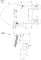
FIG. 1 is a diagram schematically showing a marine vessel including a communication system for outboard motor drive according to a preferred embodiment. -
FIG. 2 is a side view showing an outboard motor of a communication system for outboard motor drive according to a preferred embodiment. -
FIG. 3 is a diagram schematically showing a system structure of a communication system for outboard motor drive according to a preferred embodiment. -
FIG. 4 is a diagram schematically showing a state in which a communication system for outboard motor drive according to a preferred embodiment has been changed from a system including two outboard motors to a system including one outboard motor. - Preferred embodiments are hereinafter described with reference to the drawings.
- The structure of a
marine vessel 100 including acommunication system 102 for outboard motor drive according to preferred embodiments is now described with reference toFIGS. 1 to 4 . Thecommunication system 102 for outboard motor drive is an example of a "communication system for propulsion device drive". - As shown in
FIGS. 1 and 2 , themarine vessel 100 includes ahull 101 and thecommunication system 102 for outboard motor drive mounted on thehull 101. Thecommunication system 102 for outboard motor drive includes an outboard motor 1 on thehull 101. The outboard motor 1 is an example of a "marine propulsion device". - The outboard motor 1 is attached to a transom of the
hull 101. The outboard motor 1 includes afirst outboard motor 10 and asecond outboard motor 11. Thefirst outboard motor 10 and thesecond outboard motor 11 are aligned side by side along a right-left direction of thehull 101. Thefirst outboard motor 10 and thesecond outboard motor 11 have the same structure as each other. Therefore, thefirst outboard motor 10 is described below. - The
first outboard motor 10 shown inFIG. 2 is an electric propulsion device in which a propeller P is driven by an electric motor. Thefirst outboard motor 10 is a duct-driven propulsion device in which the electric motor is integral and unitary with a duct D and the propeller P. The firstoutboard motor 10 rotates the duct D and the propeller P in the right-left direction by a steering mechanism (not shown) about a central axis a. The propeller P rotates about a central axis β. - Each of the first
outboard motor 10 and the secondoutboard motor 11 includes an in-outboard motor controller C that controls driving of the electric motor, for example, that is a drive source of the propeller P. - As shown in
FIGS. 1 and3 , thecommunication system 102 for outboard motor drive includes an in-hull maneuvering controller 102a, a first terminatingresistor 2a, a second terminatingresistor 2b, amain bus line 3, astub line 4 connected to the in-hull maneuvering controller 102a,first connectors second connector 6. - The
main bus line 3 includes twosignal lines 30 to transmit data using a voltage difference between the twosignal lines 30. Themain bus line 3 is provided to communicate with the outboard motor 1 (the firstoutboard motor 10 and the second outboard motor 11). - Specifically, the two
signal lines 30 of themain bus line 3 include ahigh bus line 30a that is at a high voltage during data transmission, and alow bus line 30b that is at a low voltage during data transmission. Themain bus line 3 is based on a CAN (controller area network) communication standard and transmits data based on a voltage difference between thehigh bus line 30a and thelow bus line 30b. - That is, the
communication system 102 for outboard motor drive employs a so-called two-wire differential voltage system. In the two-wire differential voltage system, the same noise is generated on thehigh bus line 30a and thelow bus line 30b at the same time, and thus the noise does not affect the voltage difference (transmitted data) between thehigh bus line 30a and thelow bus line 30b. Therefore, the two-wire differential voltage system is a communication system with high noise resistance. - The
high bus line 30a and thelow bus line 30b of themain bus line 3 have substantially the same lengths. Thehigh bus line 30a and thelow bus line 30b of themain bus line 3 are provided in parallel to each other. Thehigh bus line 30a and thelow bus line 30b of themain bus line 3 are twisted together and connect the first terminatingresistor 2a to the second terminatingresistor 2b. - The in-
hull maneuvering controller 102a is located at afirst end 3a of themain bus line 3 in thehull 101. The in-hull maneuvering controller 102a controls driving of the outboard motor 1 (the firstoutboard motor 10 and the second outboard motor 11). The in-hull maneuvering controller 102a includes a CPU and a memory. - As an example, the in-
hull maneuvering controller 102a includes a so-called boat control unit to adjust driving of the firstoutboard motor 10 and the secondoutboard motor 11 to perform automatic marine vessel maneuvering. In addition, the in-hull maneuvering controller may include a master remote control ECU of remote control ECUs provided one for each outboard motor, for example. - The in-outboard motor controller C includes a first in-outboard motor controller C1 and a second in-outboard motor controller C2. The first
outboard motor 10 includes the first in-outboard motor controller C1. The secondoutboard motor 11 includes the second in-outboard motor controller C2. The first in-outboard motor controller C1 and the second in-outboard motor controller C2 have the same structure as each other. Each of the first in-outboard motor controller C1 and the second in-outboard motor controller C2 includes a CPU and a memory. - The first terminating
resistor 2a is provided in the in-hull maneuvering controller 102a located at thefirst end 3a of themain bus line 3. The first terminatingresistor 2a electrically connects the two signal lines 30 (thehigh bus line 30a and thelow bus line 30b). The first terminatingresistor 2a reduces or prevents signal reflection generated at terminations of thehigh bus line 30a and thelow bus line 30b (thefirst end 3a of the main bus line 3) during data transmission. In short, the first terminatingresistor 2a reduces or prevents noise by consuming reflected energy that causes noise. - The second terminating
resistor 2b is provided at asecond end 3b of themain bus line 3. The second terminatingresistor 2b electrically connects the two signal lines 30 (thehigh bus line 30a and thelow bus line 30b). The second terminatingresistor 2b reduces or prevents signal reflection generated at terminations of thehigh bus line 30a and thelow bus line 30b (thesecond end 3b of the main bus line 3) during data transmission. In short, the second terminatingresistor 2b reduces or prevents noise by consuming reflected energy that causes noise. - The
communication system 102 for outboard motor drive includes only two terminating resistors, the first terminatingresistor 2a and the second terminatingresistor 2b. - The
main bus line 3 is connected to the second terminatingresistor 2b located in thehull 101 by passing through the outboard motor 1 from the first terminatingresistor 2a side and making a U-turn. Specifically, themain bus line 3 includes aU-turn line 33 that is a folded portion that makes a U-turn outside thehull 101 and is connected to the in-outboard motor controller C via thestub line 4. - The
main bus line 3 includes a first end-side line 31 connected to the first terminatingresistor 2a in thehull 101, and a second end-side line 32 connected to the second terminatingresistor 2b in thehull 101. - The
U-turn line 33 includes afirst U-turn line 33a and asecond U-turn line 33b. In themain bus line 3, the first end-side line 31 is connected to the second end-side line 32 by theU-turn line 33 that makes a U-turn outside thehull 101. The outside of thehull 101 in which theU-turn line 33 makes a U-turn corresponds to the inside of the firstoutboard motor 10 and the inside of the secondoutboard motor 11. - The
stub line 4 includes afirst stub line 4a and asecond stub line 4b. Thefirst stub line 4a connects themain bus line 3 to the first in-outboard motor controller C1. Thesecond stub line 4b connects themain bus line 3 to the second in-outboard motor controller C2. - The
first U-turn line 33a is connected to the first in-outboard motor controller C1 via thefirst stub line 4a, and is connected to the first end-side line 31. Thesecond U-turn line 33b is connected to the second in-outboard motor controller C2 via thesecond stub line 4b, and is connected to the second end-side line 32. Thefirst U-turn line 33a and thesecond U-turn line 33b, each of which is a portion of themain bus line 3, have the same structure as each other. - The
main bus line 3 includes aconnection line 34. Theconnection line 34 connects thefirst U-turn line 33a to thesecond U-turn line 33b outside the outboard motor 1 (between the firstoutboard motor 10 and the second outboard motor 11). - Each of the first end-
side line 31, the second end-side line 32, thefirst U-turn line 33a, thesecond U-turn line 33b, and theconnection line 34 includes thehigh bus line 30a and thelow bus line 30b in parallel to each other. - The
U-turn line 33 of themain bus line 3 is attachable to and detachable from the first end-side line 31 and the second end-side line 32. Thefirst connectors U-turn line 33 to and from the first end-side line 31 and the second end-side line 32. - The
first U-turn line 33a and thefirst stub line 4a are located inside the firstoutboard motor 10. Thesecond U-turn line 33b and thesecond stub line 4b are located inside the secondoutboard motor 11. - The
first connector 5a is integral and unitary with the firstoutboard motor 10. Thefirst connector 5b is integral and unitary with the secondoutboard motor 11. Thefirst connectors U-turn line 33 to the first end-side line 31 and the second end-side line 32. - Specifically, the
first connector 5a connects thefirst U-turn line 33a to the first end-side line 31. Thus, thefirst U-turn line 33a and the first end-side line 31 are electrically connected to each other via thefirst connector 5a. Thefirst connector 5b connects thesecond U-turn line 33b to the second end-side line 32. Thus, thesecond U-turn line 33b and the second end-side line 32 are electrically connected to each other via thefirst connector 5b. - The
first connector 5a connects thefirst U-turn line 33a to a first end of theconnection line 34. Thus, thefirst U-turn line 33a and theconnection line 34 are electrically connected to each other via thefirst connector 5a. Thefirst connector 5b connects thesecond U-turn line 33b to a second end of theconnection line 34. Thus, thesecond U-turn line 33b and theconnection line 34 are electrically connected to each other via thefirst connector 5b. - Therefore, the first end-
side line 31 and the second end-side line 32 are electrically connected to each other via thefirst connector 5a, thefirst U-turn line 33a, theconnection line 34, thefirst connector 5b, and thesecond U-turn line 33b. - The first end-
side line 31 includes afirst line 31a closer to the first terminatingresistor 2a and asecond line 31b closer to thefirst connectors second connector 6 detachably connects thefirst line 31a to thesecond line 31b in thehull 101. - As shown in
FIG. 4 , thecommunication system 102 for outboard motor drive is easily changed from a system including two outboard motors to a system including one outboard motor by rearranging the system components. - Specifically, the second end-
side line 32 is detached from thefirst connector 5b, and theconnection line 34 is detached from thefirst connector 5a. Then, the second end-side line 32 is connected to a position of thefirst connector 5a to which theconnection line 34 used to be connected. Consequently, thecommunication system 102 for outboard motor drive is changed from a system including two outboard motors to a system including one outboard motor. In such a case, amain bus line 103 includes the first end-side line 31, thefirst U-turn line 33a, and the second end-side line 32. - Furthermore, the
communication system 102 for outboard motor drive is easily changed from a system including two outboard motors to a system including three or more outboard motors by rearranging the system components. - According to the various preferred embodiments described above, the following advantageous effects are achieved.
- According to a preferred embodiment, the
communication system 102 for outboard motor drive includes the first terminatingresistor 2a in the in-hull maneuvering controller 102a to electrically connect the twosignal lines 30, and the second terminatingresistor 2b at thesecond end 3b of themain bus line 3 to electrically connect the twosignal lines 30, and themain bus line 3 is connected to the second terminatingresistor 2b in thehull 101 by passing through the outboard motor 1 from the first terminatingresistor 2a side and making a U-turn. Accordingly, themain bus line 3 makes a U-turn, and thus themain bus line 3 is returned into thehull 101 after passing through the outboard motor 1 such that both ends of themain bus line 3 are located in thehull 101. Therefore, the two terminating resistors, the first terminatingresistor 2a and the second terminatingresistor 2b, are located in thehull 101 such that the terminating resistors are removed from inside the outboard motor 1. Thus, the number of terminating resistors does not vary depending on the number of outboard motors 1 unlike the conventional case, and the number of terminating resistors in the communication system is minimized. Consequently, generation of an unused terminating resistor is prevented. - According to a preferred embodiment, the
communication system 102 for outboard motor drive further includes the in-outboard motor controller C configured or programmed to control driving of the outboard motor 1, and thestub line 4 connected to the in-outboard motor controller C, and themain bus line 3 includes theU-turn line 33 that is the folded portion that makes a U-turn outside thehull 101 and is connected to the in-outboard motor controller C via thestub line 4. Accordingly, thestub line 4 and theU-turn line 33 facilitate communication between the in-hull maneuvering controller 102a and the in-outboard motor controller C, and themain bus line 3 is easily returned into thehull 101 from inside the outboard motor 1. - According to a preferred embodiment, the
main bus line 3 includes the first end-side line 31 connected to the first terminatingresistor 2a in thehull 101, and the second end-side line 32 connected to the second terminatingresistor 2b in thehull 101, and the first end-side line 31 is connected to the second end-side line 32 by theU-turn line 33 that makes a U-turn outside thehull 101. Furthermore, theU-turn line 33 is attachable to and detachable from the first end-side line 31 and the second end-side line 32. Accordingly, theU-turn line 33 is attachable to and detachable from the first end-side line 31 and the second end-side line 32, and thus the lines are easily connected to each other. - According to a preferred embodiment, the outboard motor 1 includes the first
outboard motor 10 including the first in-outboard motor controller C1 as the in-outboard motor controller C, and the secondoutboard motor 11 including the second in-outboard motor controller C2 as the in-outboard motor controller C. Thestub line 4 includes thefirst stub line 4a to connect themain bus line 3 to the first in-outboard motor controller C1, and thesecond stub line 4b to connect themain bus line 3 to the second in-outboard motor controller C2. TheU-turn line 33 includes thefirst U-turn line 33a connected to the first in-outboard motor controller C1 via thefirst stub line 4a and connected to the first end-side line 31, and thesecond U-turn line 33b connected to the second in-outboard motor controller C2 via thesecond stub line 4b and connected to the second end-side line 32. Themain bus line 3 further includes theconnection line 34 to connect thefirst U-turn line 33a to thesecond U-turn line 33b. Accordingly, thefirst stub line 4a, thesecond stub line 4b, thefirst U-turn line 33a, and thesecond U-turn line 33b facilitate communication between the in-hull maneuvering controller 102a, the first in-outboard motor controller C1, and the second in-outboard motor controller C2, and themain bus line 3 is easily returned into thehull 101 from inside the outboard motor 1. - According to a preferred embodiment, the
first U-turn line 33a and thefirst stub line 4a are located inside the firstoutboard motor 10, and thesecond U-turn line 33b and thesecond stub line 4b are located inside the secondoutboard motor 11. Accordingly, thefirst U-turn line 33a and thefirst stub line 4a are housed in the firstoutboard motor 10, and thesecond U-turn line 33b and thesecond stub line 4b are housed in the secondoutboard motor 11, and thus complex wiring outside the outboard motor 1 is reduced or prevented. - According to a preferred embodiment, the
first U-turn line 33a and thesecond U-turn line 33b, each of which is a portion of themain bus line 3, have the same structure as each other. Accordingly, thefirst U-turn line 33a in the firstoutboard motor 10 and thesecond U-turn line 33b in the secondoutboard motor 11 have the same structure as each other, and thus even when the positions of the firstoutboard motor 10 and the secondoutboard motor 11 are swapped or the positions of thefirst U-turn line 33a and thesecond U-turn line 33b are swapped, the in-hull maneuvering controller 102a, the first in-outboard motor controller C1, and the second in-outboard motor controller C2 are communicably connected to each other. - According to a preferred embodiment, the
communication system 102 for outboard motor drive further includes thefirst connectors U-turn line 33 to the first end-side line 31 and the second end-side line 32. Accordingly, theU-turn line 33 is easily connected to the first end-side line 31 by thefirst connectors - According to a preferred embodiment, the
first connectors - According to a preferred embodiment, the first end-
side line 31 includes thefirst line 31a closer to the first terminatingresistor 2a, and thesecond line 31b closer to thefirst connectors communication system 102 for outboard motor drive further includes thesecond connector 6 to detachably connect thefirst line 31a to thesecond line 31b in thehull 101. Accordingly, the first end-side line 31 is shortened by being divided into two portions, thefirst line 31a and thesecond line 31b, and thus the first end-side line 31 is easily routed without tangling. Furthermore, thefirst line 31a is easily connected to thesecond line 31b by thesecond connector 6. - According to a preferred embodiment, the two
signal lines 30 of themain bus line 3 include thehigh bus line 30a that is at a high voltage during data transmission, and thelow bus line 30b that is at a low voltage during data transmission, and themain bus line 3 is based on the CAN communication standard and is operable to transmit data based on the voltage difference between thehigh bus line 30a and thelow bus line 30b. Accordingly, in thecommunication system 102 for outboard motor drive based on the CAN communication standard, generation of an unused termination resistor is prevented. - According to a preferred embodiment, the
high bus line 30a and thelow bus line 30b of themain bus line 3 are twisted together and are operable to connect the first terminatingresistor 2a to the second terminatingresistor 2b. Accordingly, thehigh bus line 30a and thelow bus line 30b are a so-called twisted cable, and thus noise during data transmission is reduced. - The preferred embodiments described above are illustrative for present teaching but the present teaching also relates to modifications of the preferred embodiments.
- For example, while the marine vessel preferably includes the outboard motor in preferred embodiments described above, the present teaching is not restricted to this. In the present teaching, the marine vessel may alternatively include an inboard-outboard motor, for example, instead of the outboard motor.
- While the marine vessel preferably includes one or two outboard motors in preferred embodiments described above, the present teaching is not restricted to this. In the present teaching, the marine vessel may alternatively include three or more outboard motors.
- While the outboard motor is preferably electrically driven with an electric motor as a drive source in preferred embodiments described above, the present teaching is not restricted to this. In the present teaching, the outboard motor may alternatively be an engine-driven with an engine as a drive source.
- While the marine vessel preferably includes the first connectors in preferred embodiments described above, the present teaching is not restricted to this. In the present teaching, the marine vessel may not include the first connectors.
- While the marine vessel preferably includes the second connector in preferred embodiments described above, the present teaching is not restricted to this. In the present teaching, the marine vessel may not include the second connector.
- While the main bus line is preferably based on the CAN communication standard and preferably transmits data based on the voltage difference between the high bus line and the low bus line in preferred embodiments described above, the present teaching is not restricted to this. In the present teaching, the main bus line may alternatively be based on a two-wire differential voltage system standard different from the CAN communication standard.
Claims (11)
- A communication system (102) for outboard motor drive, the communication system comprising:a main bus line (3, 103) including two signal lines (30) configured to transmit data using a voltage difference between the two signal lines, and configured to communicate with an outboard motor (1);an in-hull maneuvering controller (102a) provided at a first end (3a) of the main bus line in a hull (101);a first terminating resistor (2a) provided in the in-hull maneuvering controller and configured to electrically connect the two signal lines; anda second terminating resistor (2b) provided at a second end (3b) of the main bus line and configured to electrically connect the two signal lines; whereinthe main bus line is connected to the second terminating resistor provided in the hull by passing through the outboard motor from a side of the first terminating resistor and making a U-turn.
- The communication system for outboard motor drive according to claim 1, further comprising:an in-outboard motor controller (C) configured or programmed to control driving of the outboard motor; anda stub line (4) connected to the in-outboard motor controller; whereinthe main bus line includes a U-turn line (33) that is a folded portion configured to make a U-turn outside the hull and is connected to the in-outboard motor controller via the stub line.
- The communication system for outboard motor drive according to claim 2, whereinthe main bus line includes a first end-side line (31) connected to the first terminating resistor in the hull, and a second end-side line (32) connected to the second terminating resistor in the hull;the first end-side line is connected to the second end-side line by the U-turn line configured to make a U-turn outside the hull; andthe U-turn line is configured to be attachable to and detachable from the first end-side line and the second end-side line.
- The communication system for outboard motor drive according to claim 3, whereinthe outboard motor includes a first outboard motor (10) including a first in-outboard motor controller (C1) as the in-outboard motor controller, and a second outboard motor (11) including a second in-outboard motor controller (C2) as the in-outboard motor controller;the stub line includes a first stub line (4a) configured to connect the main bus line to the first in-outboard motor controller, and a second stub line (4b) configured to connect the main bus line to the second in-outboard motor controller;the U-turn line includes a first U-turn line (33a) connected to the first in-outboard motor controller via the first stub line and connected to the first end-side line, and a second U-turn line (33b) connected to the second in-outboard motor controller via the second stub line and connected to the second end-side line; andthe main bus line further includes a connection line (34) configured to connect the first U-turn line to the second U-turn line.
- The communication system for outboard motor drive according to claim 4, whereinthe first U-turn line and the first stub line are located inside the first outboard motor; andthe second U-turn line and the second stub line are located inside the second outboard motor.
- The communication system for outboard motor drive according to claim 4, wherein the first U-turn line and the second U-turn line, each of which is a portion of the main bus line, have the same structure as each other.
- The communication system for outboard motor drive according to claim 3, further comprising:
a first connector (5a, 5b) configured to detachably connect the U-turn line to the first end-side line and the second end-side line. - The communication system for outboard motor drive according to claim 7, wherein the first connector is integral and unitary with the outboard motor.
- The communication system for outboard motor drive according to claim 7, whereinthe first end-side line includes a first line (31a) provided closer to the first terminating resistor, and a second line (31b) provided closer to the first connector; andthe communication system for outboard motor drive further comprises a second connector (6) configured to detachably connect the first line to the second line in the hull.
- The communication system for outboard motor drive according to claim 1, whereinthe two signal lines of the main bus line include a high bus line (30a) configured to be at a high voltage during data transmission, and a low bus line (30b) configured to be at a low voltage during data transmission; andthe main bus line is based on a CAN communication standard and is configured to transmit data based on a voltage difference between the high bus line and the low bus line.
- The communication system for outboard motor drive according to claim 10, wherein the high bus line and the low bus line of the main bus line are twisted together and are configured to connect the first terminating resistor to the second terminating resistor.
Applications Claiming Priority (1)
| Application Number | Priority Date | Filing Date | Title |
|---|---|---|---|
| JP2023003874A JP2024100125A (en) | 2023-01-13 | 2023-01-13 | Communication system for driving outboard motors, communication system for driving ships and propulsion units |
Publications (1)
| Publication Number | Publication Date |
|---|---|
| EP4401326A1 true EP4401326A1 (en) | 2024-07-17 |
Family
ID=89119203
Family Applications (1)
| Application Number | Title | Priority Date | Filing Date |
|---|---|---|---|
| EP23214252.1A Pending EP4401326A1 (en) | 2023-01-13 | 2023-12-05 | Communication system for outboard motor drive |
Country Status (3)
| Country | Link |
|---|---|
| US (1) | US20240239467A1 (en) |
| EP (1) | EP4401326A1 (en) |
| JP (1) | JP2024100125A (en) |
Citations (1)
| Publication number | Priority date | Publication date | Assignee | Title |
|---|---|---|---|---|
| JP2007309294A (en) | 2006-05-22 | 2007-11-29 | Yamaha Marine Co Ltd | Electronic controller for remote control and remote operation system using the same |
-
2023
- 2023-01-13 JP JP2023003874A patent/JP2024100125A/en active Pending
- 2023-12-05 EP EP23214252.1A patent/EP4401326A1/en active Pending
- 2023-12-14 US US18/539,354 patent/US20240239467A1/en active Pending
Patent Citations (2)
| Publication number | Priority date | Publication date | Assignee | Title |
|---|---|---|---|---|
| JP2007309294A (en) | 2006-05-22 | 2007-11-29 | Yamaha Marine Co Ltd | Electronic controller for remote control and remote operation system using the same |
| US20080027598A1 (en) * | 2006-05-22 | 2008-01-31 | Yamaha Marine Kabushiki Kaisha | Electronic control device for remote control and teleoperation system using same |
Also Published As
| Publication number | Publication date |
|---|---|
| US20240239467A1 (en) | 2024-07-18 |
| JP2024100125A (en) | 2024-07-26 |
Similar Documents
| Publication | Publication Date | Title |
|---|---|---|
| US6595811B2 (en) | Personal watercraft vehicle component multiplex communication system | |
| US8682515B2 (en) | Marine vessel control system, marine vessel propulsion system, and marine vessel | |
| JP4907935B2 (en) | Ship | |
| CN100591576C (en) | propulsion system | |
| US10017136B1 (en) | Outboard motor and rigging system for outboard motor | |
| US8858280B1 (en) | Marine engine rigging system | |
| US12286206B2 (en) | Marine vessel maneuvering system and marine vessel | |
| JP4666492B2 (en) | Ship | |
| JP2014521538A (en) | Data communication interface for agricultural utility vehicles | |
| US7957891B2 (en) | Electronic control device for remote control and teleoperation system using same | |
| US20240239467A1 (en) | Communication system for outboard motor, marine vessel, and communication system for propulsion device | |
| JP4471210B2 (en) | Multi-engine power supply system for marine LAN systems | |
| US6963146B2 (en) | Modular power control apparatus | |
| EP1770007B1 (en) | Boat | |
| US7144283B2 (en) | Boat LAN system | |
| CN111332230A (en) | CAN communication terminal resistor module of hydrogen fuel electric vehicle | |
| EP0388228B1 (en) | Mounting and control of outboard motors | |
| JP2006067543A (en) | Connector, in-vehicle bus drive device, protection circuit, adapter, in-vehicle bus branch wire harness, in-vehicle bus branch waveform shaping device, and in-vehicle bus joint connector | |
| KR200294520Y1 (en) | A Steering Wheel Box for A Ship Operation | |
| Piętak et al. | On the adaptation of CAN BUS network for use in the ship electronic systems | |
| CN223494408U (en) | LIN communication controller of borderless external rearview mirror | |
| CN223414409U (en) | A domain controller Gigabit Ethernet harness | |
| CN222965886U (en) | External terminal resistor and aircraft | |
| US20250388310A1 (en) | Steering device | |
| JP3293338B2 (en) | In-vehicle electronic control device and its failure diagnosis method |
Legal Events
| Date | Code | Title | Description |
|---|---|---|---|
| PUAI | Public reference made under article 153(3) epc to a published international application that has entered the european phase |
Free format text: ORIGINAL CODE: 0009012 |
|
| STAA | Information on the status of an ep patent application or granted ep patent |
Free format text: STATUS: THE APPLICATION HAS BEEN PUBLISHED |
|
| AK | Designated contracting states |
Kind code of ref document: A1 Designated state(s): AL AT BE BG CH CY CZ DE DK EE ES FI FR GB GR HR HU IE IS IT LI LT LU LV MC ME MK MT NL NO PL PT RO RS SE SI SK SM TR |
|
| P01 | Opt-out of the competence of the unified patent court (upc) registered |
Free format text: CASE NUMBER: APP_64542/2024 Effective date: 20241205 |
|
| STAA | Information on the status of an ep patent application or granted ep patent |
Free format text: STATUS: REQUEST FOR EXAMINATION WAS MADE |
|
| 17P | Request for examination filed |
Effective date: 20250117 |