EP4401292A1 - Converter system for vehicle - Google Patents
Converter system for vehicle Download PDFInfo
- Publication number
- EP4401292A1 EP4401292A1 EP23212998.1A EP23212998A EP4401292A1 EP 4401292 A1 EP4401292 A1 EP 4401292A1 EP 23212998 A EP23212998 A EP 23212998A EP 4401292 A1 EP4401292 A1 EP 4401292A1
- Authority
- EP
- European Patent Office
- Prior art keywords
- converter
- gate driver
- control
- switch
- electrically connected
- Prior art date
- Legal status (The legal status is an assumption and is not a legal conclusion. Google has not performed a legal analysis and makes no representation as to the accuracy of the status listed.)
- Pending
Links
Images
Classifications
-
- B—PERFORMING OPERATIONS; TRANSPORTING
- B60—VEHICLES IN GENERAL
- B60L—PROPULSION OF ELECTRICALLY-PROPELLED VEHICLES; SUPPLYING ELECTRIC POWER FOR AUXILIARY EQUIPMENT OF ELECTRICALLY-PROPELLED VEHICLES; ELECTRODYNAMIC BRAKE SYSTEMS FOR VEHICLES IN GENERAL; MAGNETIC SUSPENSION OR LEVITATION FOR VEHICLES; MONITORING OPERATING VARIABLES OF ELECTRICALLY-PROPELLED VEHICLES; ELECTRIC SAFETY DEVICES FOR ELECTRICALLY-PROPELLED VEHICLES
- B60L3/00—Electric devices on electrically-propelled vehicles for safety purposes; Monitoring operating variables, e.g. speed, deceleration or energy consumption
-
- B—PERFORMING OPERATIONS; TRANSPORTING
- B60—VEHICLES IN GENERAL
- B60L—PROPULSION OF ELECTRICALLY-PROPELLED VEHICLES; SUPPLYING ELECTRIC POWER FOR AUXILIARY EQUIPMENT OF ELECTRICALLY-PROPELLED VEHICLES; ELECTRODYNAMIC BRAKE SYSTEMS FOR VEHICLES IN GENERAL; MAGNETIC SUSPENSION OR LEVITATION FOR VEHICLES; MONITORING OPERATING VARIABLES OF ELECTRICALLY-PROPELLED VEHICLES; ELECTRIC SAFETY DEVICES FOR ELECTRICALLY-PROPELLED VEHICLES
- B60L53/00—Methods of charging batteries, specially adapted for electric vehicles; Charging stations or on-board charging equipment therefor; Exchange of energy storage elements in electric vehicles
- B60L53/20—Methods of charging batteries, specially adapted for electric vehicles; Charging stations or on-board charging equipment therefor; Exchange of energy storage elements in electric vehicles characterised by converters located in the vehicle
-
- H—ELECTRICITY
- H02—GENERATION; CONVERSION OR DISTRIBUTION OF ELECTRIC POWER
- H02M—APPARATUS FOR CONVERSION BETWEEN AC AND AC, BETWEEN AC AND DC, OR BETWEEN DC AND DC, AND FOR USE WITH MAINS OR SIMILAR POWER SUPPLY SYSTEMS; CONVERSION OF DC OR AC INPUT POWER INTO SURGE OUTPUT POWER; CONTROL OR REGULATION THEREOF
- H02M1/00—Details of apparatus for conversion
- H02M1/32—Means for protecting converters other than automatic disconnection
-
- B—PERFORMING OPERATIONS; TRANSPORTING
- B60—VEHICLES IN GENERAL
- B60L—PROPULSION OF ELECTRICALLY-PROPELLED VEHICLES; SUPPLYING ELECTRIC POWER FOR AUXILIARY EQUIPMENT OF ELECTRICALLY-PROPELLED VEHICLES; ELECTRODYNAMIC BRAKE SYSTEMS FOR VEHICLES IN GENERAL; MAGNETIC SUSPENSION OR LEVITATION FOR VEHICLES; MONITORING OPERATING VARIABLES OF ELECTRICALLY-PROPELLED VEHICLES; ELECTRIC SAFETY DEVICES FOR ELECTRICALLY-PROPELLED VEHICLES
- B60L3/00—Electric devices on electrically-propelled vehicles for safety purposes; Monitoring operating variables, e.g. speed, deceleration or energy consumption
- B60L3/0023—Detecting, eliminating, remedying or compensating for drive train abnormalities, e.g. failures within the drive train
- B60L3/0046—Detecting, eliminating, remedying or compensating for drive train abnormalities, e.g. failures within the drive train relating to electric energy storage systems, e.g. batteries or capacitors
-
- B—PERFORMING OPERATIONS; TRANSPORTING
- B60—VEHICLES IN GENERAL
- B60L—PROPULSION OF ELECTRICALLY-PROPELLED VEHICLES; SUPPLYING ELECTRIC POWER FOR AUXILIARY EQUIPMENT OF ELECTRICALLY-PROPELLED VEHICLES; ELECTRODYNAMIC BRAKE SYSTEMS FOR VEHICLES IN GENERAL; MAGNETIC SUSPENSION OR LEVITATION FOR VEHICLES; MONITORING OPERATING VARIABLES OF ELECTRICALLY-PROPELLED VEHICLES; ELECTRIC SAFETY DEVICES FOR ELECTRICALLY-PROPELLED VEHICLES
- B60L58/00—Methods or circuit arrangements for monitoring or controlling batteries or fuel cells, specially adapted for electric vehicles
- B60L58/10—Methods or circuit arrangements for monitoring or controlling batteries or fuel cells, specially adapted for electric vehicles for monitoring or controlling batteries
- B60L58/12—Methods or circuit arrangements for monitoring or controlling batteries or fuel cells, specially adapted for electric vehicles for monitoring or controlling batteries responding to state of charge [SoC]
-
- B—PERFORMING OPERATIONS; TRANSPORTING
- B60—VEHICLES IN GENERAL
- B60L—PROPULSION OF ELECTRICALLY-PROPELLED VEHICLES; SUPPLYING ELECTRIC POWER FOR AUXILIARY EQUIPMENT OF ELECTRICALLY-PROPELLED VEHICLES; ELECTRODYNAMIC BRAKE SYSTEMS FOR VEHICLES IN GENERAL; MAGNETIC SUSPENSION OR LEVITATION FOR VEHICLES; MONITORING OPERATING VARIABLES OF ELECTRICALLY-PROPELLED VEHICLES; ELECTRIC SAFETY DEVICES FOR ELECTRICALLY-PROPELLED VEHICLES
- B60L58/00—Methods or circuit arrangements for monitoring or controlling batteries or fuel cells, specially adapted for electric vehicles
- B60L58/10—Methods or circuit arrangements for monitoring or controlling batteries or fuel cells, specially adapted for electric vehicles for monitoring or controlling batteries
- B60L58/18—Methods or circuit arrangements for monitoring or controlling batteries or fuel cells, specially adapted for electric vehicles for monitoring or controlling batteries of two or more battery modules
- B60L58/20—Methods or circuit arrangements for monitoring or controlling batteries or fuel cells, specially adapted for electric vehicles for monitoring or controlling batteries of two or more battery modules having different nominal voltages
-
- B—PERFORMING OPERATIONS; TRANSPORTING
- B60—VEHICLES IN GENERAL
- B60R—VEHICLES, VEHICLE FITTINGS, OR VEHICLE PARTS, NOT OTHERWISE PROVIDED FOR
- B60R16/00—Electric or fluid circuits specially adapted for vehicles and not otherwise provided for; Arrangement of elements of electric or fluid circuits specially adapted for vehicles and not otherwise provided for
- B60R16/02—Electric or fluid circuits specially adapted for vehicles and not otherwise provided for; Arrangement of elements of electric or fluid circuits specially adapted for vehicles and not otherwise provided for electric constitutive elements
- B60R16/03—Electric or fluid circuits specially adapted for vehicles and not otherwise provided for; Arrangement of elements of electric or fluid circuits specially adapted for vehicles and not otherwise provided for electric constitutive elements for supply of electrical power to vehicle subsystems or for
- B60R16/033—Electric or fluid circuits specially adapted for vehicles and not otherwise provided for; Arrangement of elements of electric or fluid circuits specially adapted for vehicles and not otherwise provided for electric constitutive elements for supply of electrical power to vehicle subsystems or for characterised by the use of electrical cells or batteries
-
- H—ELECTRICITY
- H02—GENERATION; CONVERSION OR DISTRIBUTION OF ELECTRIC POWER
- H02J—ELECTRIC POWER NETWORKS; CIRCUIT ARRANGEMENTS OR SYSTEMS FOR SUPPLYING OR DISTRIBUTING ELECTRIC POWER; SYSTEMS FOR STORING ELECTRIC ENERGY
- H02J7/00—Circuit arrangements for charging or discharging batteries or for supplying loads from batteries
- H02J7/34—Parallel operation in networks using both storage and other DC sources, e.g. providing buffering
- H02J7/342—The other DC source being a battery actively interacting with the first one, i.e. battery to battery charging
-
- H—ELECTRICITY
- H02—GENERATION; CONVERSION OR DISTRIBUTION OF ELECTRIC POWER
- H02M—APPARATUS FOR CONVERSION BETWEEN AC AND AC, BETWEEN AC AND DC, OR BETWEEN DC AND DC, AND FOR USE WITH MAINS OR SIMILAR POWER SUPPLY SYSTEMS; CONVERSION OF DC OR AC INPUT POWER INTO SURGE OUTPUT POWER; CONTROL OR REGULATION THEREOF
- H02M1/00—Details of apparatus for conversion
- H02M1/08—Circuits specially adapted for the generation of control voltages for semiconductor devices incorporated in static converters
-
- H—ELECTRICITY
- H02—GENERATION; CONVERSION OR DISTRIBUTION OF ELECTRIC POWER
- H02M—APPARATUS FOR CONVERSION BETWEEN AC AND AC, BETWEEN AC AND DC, OR BETWEEN DC AND DC, AND FOR USE WITH MAINS OR SIMILAR POWER SUPPLY SYSTEMS; CONVERSION OF DC OR AC INPUT POWER INTO SURGE OUTPUT POWER; CONTROL OR REGULATION THEREOF
- H02M3/00—Conversion of DC power input into DC power output
- H02M3/02—Conversion of DC power input into DC power output without intermediate conversion into AC
- H02M3/04—Conversion of DC power input into DC power output without intermediate conversion into AC by static converters
- H02M3/10—Conversion of DC power input into DC power output without intermediate conversion into AC by static converters using discharge tubes with control electrode or semiconductor devices with control electrode
- H02M3/145—Conversion of DC power input into DC power output without intermediate conversion into AC by static converters using discharge tubes with control electrode or semiconductor devices with control electrode using devices of a triode or transistor type requiring continuous application of a control signal
- H02M3/155—Conversion of DC power input into DC power output without intermediate conversion into AC by static converters using discharge tubes with control electrode or semiconductor devices with control electrode using devices of a triode or transistor type requiring continuous application of a control signal using semiconductor devices only
- H02M3/156—Conversion of DC power input into DC power output without intermediate conversion into AC by static converters using discharge tubes with control electrode or semiconductor devices with control electrode using devices of a triode or transistor type requiring continuous application of a control signal using semiconductor devices only with automatic control of output voltage or current, e.g. switching regulators
- H02M3/158—Conversion of DC power input into DC power output without intermediate conversion into AC by static converters using discharge tubes with control electrode or semiconductor devices with control electrode using devices of a triode or transistor type requiring continuous application of a control signal using semiconductor devices only with automatic control of output voltage or current, e.g. switching regulators including plural semiconductor devices as final control devices for a single load
- H02M3/1582—Buck-boost converters
-
- H—ELECTRICITY
- H02—GENERATION; CONVERSION OR DISTRIBUTION OF ELECTRIC POWER
- H02M—APPARATUS FOR CONVERSION BETWEEN AC AND AC, BETWEEN AC AND DC, OR BETWEEN DC AND DC, AND FOR USE WITH MAINS OR SIMILAR POWER SUPPLY SYSTEMS; CONVERSION OF DC OR AC INPUT POWER INTO SURGE OUTPUT POWER; CONTROL OR REGULATION THEREOF
- H02M3/00—Conversion of DC power input into DC power output
- H02M3/22—Conversion of DC power input into DC power output with intermediate conversion into AC
- H02M3/24—Conversion of DC power input into DC power output with intermediate conversion into AC by static converters
- H02M3/28—Conversion of DC power input into DC power output with intermediate conversion into AC by static converters using discharge tubes with control electrode or semiconductor devices with control electrode to produce the intermediate AC
- H02M3/325—Conversion of DC power input into DC power output with intermediate conversion into AC by static converters using discharge tubes with control electrode or semiconductor devices with control electrode to produce the intermediate AC using devices of a triode or a transistor type requiring continuous application of a control signal
- H02M3/335—Conversion of DC power input into DC power output with intermediate conversion into AC by static converters using discharge tubes with control electrode or semiconductor devices with control electrode to produce the intermediate AC using devices of a triode or a transistor type requiring continuous application of a control signal using semiconductor devices only
- H02M3/33569—Conversion of DC power input into DC power output with intermediate conversion into AC by static converters using discharge tubes with control electrode or semiconductor devices with control electrode to produce the intermediate AC using devices of a triode or a transistor type requiring continuous application of a control signal using semiconductor devices only having several active switching elements
- H02M3/33576—Conversion of DC power input into DC power output with intermediate conversion into AC by static converters using discharge tubes with control electrode or semiconductor devices with control electrode to produce the intermediate AC using devices of a triode or a transistor type requiring continuous application of a control signal using semiconductor devices only having several active switching elements having at least one active switching element at the secondary side of an isolation transformer
- H02M3/33584—Bidirectional converters
-
- B—PERFORMING OPERATIONS; TRANSPORTING
- B60—VEHICLES IN GENERAL
- B60L—PROPULSION OF ELECTRICALLY-PROPELLED VEHICLES; SUPPLYING ELECTRIC POWER FOR AUXILIARY EQUIPMENT OF ELECTRICALLY-PROPELLED VEHICLES; ELECTRODYNAMIC BRAKE SYSTEMS FOR VEHICLES IN GENERAL; MAGNETIC SUSPENSION OR LEVITATION FOR VEHICLES; MONITORING OPERATING VARIABLES OF ELECTRICALLY-PROPELLED VEHICLES; ELECTRIC SAFETY DEVICES FOR ELECTRICALLY-PROPELLED VEHICLES
- B60L2210/00—Converter types
- B60L2210/10—DC to DC converters
-
- B—PERFORMING OPERATIONS; TRANSPORTING
- B60—VEHICLES IN GENERAL
- B60L—PROPULSION OF ELECTRICALLY-PROPELLED VEHICLES; SUPPLYING ELECTRIC POWER FOR AUXILIARY EQUIPMENT OF ELECTRICALLY-PROPELLED VEHICLES; ELECTRODYNAMIC BRAKE SYSTEMS FOR VEHICLES IN GENERAL; MAGNETIC SUSPENSION OR LEVITATION FOR VEHICLES; MONITORING OPERATING VARIABLES OF ELECTRICALLY-PROPELLED VEHICLES; ELECTRIC SAFETY DEVICES FOR ELECTRICALLY-PROPELLED VEHICLES
- B60L2210/00—Converter types
- B60L2210/10—DC to DC converters
- B60L2210/12—Buck converters
-
- B—PERFORMING OPERATIONS; TRANSPORTING
- B60—VEHICLES IN GENERAL
- B60L—PROPULSION OF ELECTRICALLY-PROPELLED VEHICLES; SUPPLYING ELECTRIC POWER FOR AUXILIARY EQUIPMENT OF ELECTRICALLY-PROPELLED VEHICLES; ELECTRODYNAMIC BRAKE SYSTEMS FOR VEHICLES IN GENERAL; MAGNETIC SUSPENSION OR LEVITATION FOR VEHICLES; MONITORING OPERATING VARIABLES OF ELECTRICALLY-PROPELLED VEHICLES; ELECTRIC SAFETY DEVICES FOR ELECTRICALLY-PROPELLED VEHICLES
- B60L2210/00—Converter types
- B60L2210/10—DC to DC converters
- B60L2210/14—Boost converters
-
- B—PERFORMING OPERATIONS; TRANSPORTING
- B60—VEHICLES IN GENERAL
- B60Y—INDEXING SCHEME RELATING TO ASPECTS CROSS-CUTTING VEHICLE TECHNOLOGY
- B60Y2306/00—Other features of vehicle sub-units
- B60Y2306/13—Failsafe arrangements
-
- H—ELECTRICITY
- H02—GENERATION; CONVERSION OR DISTRIBUTION OF ELECTRIC POWER
- H02J—ELECTRIC POWER NETWORKS; CIRCUIT ARRANGEMENTS OR SYSTEMS FOR SUPPLYING OR DISTRIBUTING ELECTRIC POWER; SYSTEMS FOR STORING ELECTRIC ENERGY
- H02J2105/00—Networks for supplying or distributing electric power characterised by their spatial reach or by the load
- H02J2105/30—Networks for supplying or distributing electric power characterised by their spatial reach or by the load the load networks being external to vehicles, i.e. exchanging power with vehicles
- H02J2105/33—Networks for supplying or distributing electric power characterised by their spatial reach or by the load the load networks being external to vehicles, i.e. exchanging power with vehicles exchanging power with road vehicles
- H02J2105/37—Networks for supplying or distributing electric power characterised by their spatial reach or by the load the load networks being external to vehicles, i.e. exchanging power with vehicles exchanging power with road vehicles exchanging power with electric vehicles [EV] or with hybrid electric vehicles [HEV]
-
- H—ELECTRICITY
- H02—GENERATION; CONVERSION OR DISTRIBUTION OF ELECTRIC POWER
- H02J—ELECTRIC POWER NETWORKS; CIRCUIT ARRANGEMENTS OR SYSTEMS FOR SUPPLYING OR DISTRIBUTING ELECTRIC POWER; SYSTEMS FOR STORING ELECTRIC ENERGY
- H02J2207/00—Details of circuit arrangements for charging or discharging batteries or supplying loads from batteries
- H02J2207/20—Charging or discharging characterised by the power electronics converter
-
- H—ELECTRICITY
- H02—GENERATION; CONVERSION OR DISTRIBUTION OF ELECTRIC POWER
- H02M—APPARATUS FOR CONVERSION BETWEEN AC AND AC, BETWEEN AC AND DC, OR BETWEEN DC AND DC, AND FOR USE WITH MAINS OR SIMILAR POWER SUPPLY SYSTEMS; CONVERSION OF DC OR AC INPUT POWER INTO SURGE OUTPUT POWER; CONTROL OR REGULATION THEREOF
- H02M1/00—Details of apparatus for conversion
- H02M1/36—Means for starting or stopping converters
Definitions
- aspects of some embodiments of the present disclosure relate to a converter system for a vehicle.
- environmentally-friendly vehicles such as pure electrical vehicles and hydrogen vehicles, as well as hybrid or plug-in hybrid vehicles and mild hybrid vehicles.
- a mild hybrid vehicle may be driven through an internal combustion engine and may be provided with additional power from a main battery.
- a converter and other electrical components may be interposed between the main battery and an auxiliary battery for the electric load, and may be mounted to charge the auxiliary battery from the main battery.
- the main battery may also be charged by regenerative braking.
- a DC/DC converter may be installed between a high-voltage main battery and a low-voltage auxiliary battery.
- the DC/DC converter may receive a control signal from a converter controller included in a vehicle, and convert a high voltage output of the main battery into a required voltage according to a control signal to charge the auxiliary battery.
- the output voltage of the DC/DC converter may be increased to store as much energy as possible in the auxiliary battery, and in a discharging mode of the main battery, the output voltage of the DC/DC converter may be lowered to minimize or reduce power consumption of the main battery.
- aspects of some embodiments of the present disclosure include a converter system for a vehicle, in which a battery management system can control driving of a bi-directional converter even when a converter controller fails, and thus vehicle safety can be relatively improved.
- a converter system for a vehicle includes: a bi-directional converter electrically connected between a main battery and an auxiliary battery to perform power conversion; a gate driver electrically connected to the bi-directional converter and applying a PWM signal for controlling a driving mode of the bi-directional converter; a converter controller electrically connected to the gate driver and applying a control signal for controlling driving of the gate driver; a control switch interposed between the converter controller and the gate driver and connecting or disconnecting a connection between the converter controller and the gate driver; and a battery management system electrically connected to the gate driver through the control switch and applying a control signal to control driving of the gate driver when an abnormality is determined in the converter controller.
- control switch may have a common terminal connected to the gate driver, a first terminal connected to the converter controller, and a second terminal connected to the battery management system, and the common terminal may be electrically connected to the first terminal or the second terminal.
- the battery management system may control driving of the control switch according to whether there is an abnormality in the converter through communication with the converter controller.
- the battery management system may control the gate driver to drive the bi-directional converter in a buck mode.
- the battery management system may be electrically connected to the control switch and may control driving of the control switch according to whether there is an abnormality in the converter controller.
- the battery management system may be electrically connected to the main battery to monitor and control charging and discharging of the main battery.
- a converter system for a vehicle may include: a bi-directional converter electrically connected between a main battery and an auxiliary battery to perform power conversion; at least one gate driver electrically connected to the bi-directional converter and applying a PWM signal for controlling a driving mode of the bi-directional converter; a converter controller electrically connected to the gate driver and applying a control signal for controlling driving of the gate driver; a control switch interposed between the gate driver and the bi-directional converter and connecting or disconnecting a connection between the gate driver and the bi-directional converter; and a battery management system electrically connected to the gate driver and controlling driving of the bi-directional converter through the gate driver by controlling driving of the control switch when an abnormality is determined in the converter controller.
- the bi-directional converter may include: a main capacitor connected in parallel with the main battery; a first switch and a second switch connected in parallel to the main capacitor and connected in series to each other; an inductor having a first electrode connected between the first switch and the second switch, and having a second electrode connected to the auxiliary battery; and an auxiliary capacitor connected in parallel with the auxiliary battery.
- the gate driver may include: a first gate driver electrically connected between the converter controller and the control switch; and a second gate driver electrically connected between the battery management system and the control switch.
- control switch may include: a first control switch having a common electrode electrically connected to a control electrode of the first switch and electrically connecting the first gate driver or the second gate driver to the first switch; and a second control switch having a common electrode electrically connected to a control electrode of the second switch and electrically connecting the first gate driver or the second gate driver to the second switch.
- the first control switch and the second control switch may operate in the same way, and both are connected to the first gate driver, or both are electrically connected to the second gate driver.
- first, second, etc. may be used herein to describe various members, elements, regions, layers and/or sections, these members, elements, regions, layers and/or sections should not be limited by these terms. These terms are only used to distinguish one member, element, region, layer and/or section from another. Thus, for example, a first member, a first element, a first region, a first layer and/or a first section discussed below could be termed a second member, a second element, a second region, a second layer and/or a second section without departing from the teachings of the present disclosure.
- spatially relative terms such as “beneath,” “below,” “lower,” “above,” “upper,” and the like, may be used herein for ease of description to describe one element or feature's relationship to another element(s) or feature(s) as illustrated in the figures. It will be understood that the spatially relative terms are intended to encompass different orientations of the device in use or operation in addition to the orientation depicted in the figures. For example, if the element or feature in the figures is turned over, elements described as “below” or “beneath” other elements or features would then be oriented “on” or “above” the other elements or features. Thus, the term “below” can encompass both an orientation of above and below.
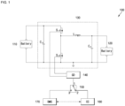
- FIG. 1 a structural diagram showing a vehicle converter system according to some embodiments of the present disclosure is shown.
- a converter system 100 for a vehicle may include a main battery 110, an auxiliary battery 120, a bi-directional converter 130, a gate driver 140, a control switch 150, a converter controller 160, and a battery management system (BMS) 170.
- BMS battery management system
- the main battery 110 may be a battery for providing driving energy (electrical energy) to a driving motor of a vehicle, and the main battery 110 may be a high voltage battery.
- the auxiliary battery 120 may be a low voltage battery operating as a battery for an electronic load of a vehicle.
- the low voltage of the auxiliary battery 120 may be a relatively low voltage, compared to the voltage of the main battery 110
- the high voltage of the main battery 110 may be a relatively high voltage, compared to the voltage of the auxiliary battery 120.
- the main battery 110 may supply power to an electrically driven auxiliary device or provide auxiliary energy in a section (period) where energy consumption is high, such as starting a vehicle.
- the electrically driven auxiliary device may include electrical components such as brakes, steering devices, and air conditioners, but embodiments according to the present disclosure are not limited thereto.
- the auxiliary battery 120 may supply power to an electronic control system for controlling electrical components of a vehicle.
- the bi-directional converter 130 is electrically connected between the main battery 110 and the auxiliary battery 120.
- the bi-directional converter 130 may include a main capacitor C in , an auxiliary capacitor C o , an inductor L 1 , a first switch S 1 , and a second switch S 2 .
- the bi-directional converter 130 may include the main capacitor C in connected in parallel with the main battery 110 and the auxiliary capacitor C o connected in parallel with the auxiliary battery 120.
- the main capacitor C in and the auxiliary capacitor C o may reduce noises by smoothing the voltages of the main battery 110 and auxiliary battery 120, respectively.
- the inductor L 1 may have a first electrode electrically connected between the second electrode of the first switch S 1 and a first electrode of the second switch S 2 , and a second electrode electrically connected to a positive electrode of the auxiliary battery 120 and the auxiliary capacitor C o .
- the first switch S 1 and the second switch S 2 are connected in series, and the first switch S 1 and the second switch S 2 connected in series are collectively connected in parallel to the main battery 110 and the main capacitor C in .
- the first electrode may be electrically connected to the positive electrode of the main battery 110 and the main capacitor C in
- the second electrode may be electrically connected to the inductor L 1 and the first electrode of the second switch S 2
- the first switch S 1 may have a control electrode electrically connected to the gate driver 140.
- the first electrode may be electrically connected to the inductor L 1 and the second electrode of the first switch S 1
- the second electrode may be electrically connected to a negative electrode of the main battery 110, a negative electrode of the auxiliary battery 120, the main capacitor C in , and the auxiliary capacitor C o .
- the second switch S 2 may have a control electrode electrically connected to the gate driver 140.
- the first switch S 1 and the second switch S 2 may be driven by a pulse width modulation (PWM) signal applied from the gate driver 140.
- PWM pulse width modulation
- the first switch S 1 and the second switch S 2 may be controlled according to the switching frequency and duty cycle applied from the gate driver 140.
- the first switch S 1 and the second switch S 2 may be composed of field effect transistors (FETs), but embodiments according to the present disclosure are not limited thereto.
- the bi-directional converter 130 may repeatedly perform the process of instantaneously storing and discharging energy in the inductor L by the PWM signal applied to the control electrodes of the first switch S 1 and the second switch S 2 , thereby performing power conversion between battery 110 and auxiliary battery 120.
- the bi-directional converter 130 may operate in a buck mode in which the output voltage of the main battery 110 is converted into a charging voltage of the auxiliary battery 120 or in a boost mode in which the output voltage of the auxiliary battery 120 is converted into the charging voltage of the main battery 110.
- the bi-directional converter 130 may generally operate in a buck mode, and may operate in a boost mode for a section (period) in which energy consumption is high in the main battery 110.
- the bi-directional converter 130 may operate in a boost mode or a buck mode by the PWM signal applied from the gate driver 140.
- the gate driver 140 may be electrically connected to the converter controller 160 or the battery management system 170 by the operation of the control switch 150.
- the gate driver 140 may receive a control signal from the converter controller 160 or the battery management system 170 to apply the PWM signal for driving the first switch S 1 and the second switch S 2 of the bi-directional converter 130.
- the control switch 150 may be a single pole double throw (SPDT) switch.
- the control switch 150 may include a common terminal 1, a first terminal 2, and a second terminal 3.
- the common terminal 1 and the first terminal 2 may be electrically connected to each other, or the common terminal 1 and the second terminal 3 may be electrically connected to each other.
- the converter controller 160 may be electrically connected to the gate driver 140 through the control switch 150.
- the control switch 150 the common terminal 1 and the first terminal 2 may be electrically connected to each other.
- the converter controller 160 may transfer a control signal to the gate driver 140 through the control switch 150, through which the gate driver 140 may control the driving mode of the bi-directional converter 130.
- the converter controller 160 may communicate with the battery management system 170.
- the converter controller 160 and the battery management system 170 may communicate through CAN communication, and when mounted on the same board, the converter controller 160 and the battery management system 170 may communicate through SPI communication.
- the communication method between the converter controller 160 and the battery management system 170 is not limited to those disclosed herein.
- the battery management system 170 may periodically check whether or not there is an abnormality in the converter controller 160 through communication.
- the battery management system 170 can control driving of the control switch 150 when it is determined that an abnormality has occurred in the converter controller 160 through communication with the converter controller 160. That is, when a failure occurs in the converter controller 160, the battery management system 170 may control the common terminal 1 and the second terminal 3 of the control switch 150 to be electrically connected to each other.
- the battery management system 170 may control driving of the bi-directional converter 130 through the gate driver 140 in an emergency mode.
- the battery management system 170 may control the bi-directional converter 130 in an emergency mode to operate in the buck mode.
- the vehicle may operate in an emergency mode under the control of the battery management system 170 to enable steering adjustment and to prevent or reduce occurrence of problems due to steering may be adjusted, and problems caused by stopping the operation of the control systems.
- the battery management system 170 may inform a driver that the vehicle is operated in an emergency mode through a dashboard, and may induce the driver to move the vehicle in an emergency mode and check an abnormal state. Even when a failure occurs in the converter controller 160, the vehicle converter system 100 can control driving of the bi-directional converter 130 in the battery management system 170, thereby relatively improving vehicle safety.
- the battery management system 170 may be electrically connected to the main battery 110, and may periodically monitor the charging/discharging state of the main battery 110. In addition, the battery management system 170 may control charging and discharging of the main battery 110.
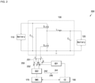
- FIG. 2 a structural diagram showing a converter system for a vehicle according to some embodiments of the present disclosure is shown.
- a converter system 200 for a vehicle may include a main battery 110, an auxiliary battery 120, a bi-directional converter 130, a gate driver 240, a control switch 250, a converter controller 160, and a battery management system 170.
- the vehicle converter system 200 may be similar to the previously described vehicle converter system 100 in terms of the main battery 110, the auxiliary battery 120, the bi-directional converter 130, the converter controller 160, and the battery management system 170.
- the gate driver 240 may include a first gate driver 241 and a second gate driver 242
- the control switch 250 may include a first control switch 251 and a second control switch 252. The following description will focus on the gate driver 240 and the control switch 250, which are different from the corresponding components of the vehicle converter system 100.
- the first control switch 251 and the second control switch 252 may be single pole double throw (SPDT) switches.
- the first control switch 251 may have a common electrode 1 electrically connected to the bi-directional converter 130, a first electrode 2 electrically connected to the first gate driver 241, and a second electrode 3 electrically connected to the second gate driver 242.
- the control electrode 1 of the first control switch 251 may be connected to a first switch S 1 of the bi-directional converter 130. That is, the first control switch 251 may control a PWM signal applied to the first switch S 1 of the bi-directional converter 130 to be applied from the first gate driver 241 or the second gate driver 242.
- the second control switch 252 may have the control electrode 1 electrically connected to the bi-directional converter 130, the first electrode 2 electrically connected to the first gate driver 241, and the second electrode 3 electrically connected to the second gate driver 242.
- the control electrode 1 of the second control switch 252 may be connected to a second switch S 2 of the bi-directional converter 130. That is, the second control switch 252 may control a PWM signal applied to the second switch S 2 of the bi-directional converter 130 to be applied to the first gate driver 241 or the second gate driver 242.
- first control switch 251 and the second control switch 252 may operate in the same way. That is, in the first control switch 251, the common electrode 1 and the first electrode 2 may be connected to each other, and in the second control switch 252, the common electrode 1 and the first electrode 2 may also be connected to each other.
- the control signals of the first control switch 251 and the second control switch 252 may be applied from the battery management system 170.
- the first switch S 1 and the second switch S 2 of the bi-directional converter 130 may receive PWM signals from the same gate driver of the first gate driver 241 and the second gate driver 242.
- the second switch S 2 may also be electrically connected to the first gate driver 241.
- the second switch S 2 may also be electrically connected to the second gate driver 242.
- the first gate driver 241 may receive a control signal from the converter controller 160 to control the operation mode of the bi-directional converter 130.
- the second gate driver 242 may receive a control signal from the battery management system 170 to control the operation mode of the bi-directional converter 130.
- the battery management system 170 may periodically check through communication whether or not there is an abnormality in the converter controller 160. Through communication with the converter controller 160, the battery management system 170 can control driving of the control switch 250 when it is determined that an abnormality has occurred in the converter controller 160. That is, when a failure occurs in the converter controller 160, the battery management system 170 may control the common terminal 1 and the second terminal 3 of the first control switch 251 and the second control switch 252 to be electrically connected to each other.
- the battery management system 170 may control the bi-directional converter 130 to supply the minimum power that the vehicle can drive in emergency mode at a low frequency, although it may be difficult to control the high-speed frequency like the converter controller 160.
- the converter controller 160 and the battery management system 170 can be separately controlled independently of each other, and even when a failure occurs in the first gate driver 241 or the second gate driver 242 as well as the converter controller 160, the bi-directional converter 130 can be safely driven, thereby improving safety.
- a battery management system can control driving of a bi-directional converter even when a converter controller fails, and thus vehicle safety can be relatively improved.
Landscapes
- Engineering & Computer Science (AREA)
- Power Engineering (AREA)
- Mechanical Engineering (AREA)
- Transportation (AREA)
- Life Sciences & Earth Sciences (AREA)
- Sustainable Development (AREA)
- Sustainable Energy (AREA)
- Electric Propulsion And Braking For Vehicles (AREA)
Abstract
A converter system for a vehicle including: a bi-directional converter electrically connected between a main battery and an auxiliary battery and configured to perform power conversion; a gate driver electrically connected to the bi-directional converter and configured to apply a PWM signal for controlling a driving mode of the bi-directional converter; a converter controller electrically connected to the gate driver and configured to apply a control signal for controlling driving of the gate driver; a control switch interposed between the converter controller and the gate driver and configured to connect or disconnect a connection between the converter controller and the gate driver; and a battery management system electrically connected to the gate driver through the control switch and configured to apply a control signal to control driving of the gate driver based on an abnormality in the converter controller.
Description
- Aspects of some embodiments of the present disclosure relate to a converter system for a vehicle.
- Recently, due to strengthening of environmental regulations including CO2 regulations, interest in environmentally-friendly vehicles has been increasing. Accordingly, vehicle companies have been actively researching and attempting to develop environmentally-friendly vehicles such as pure electrical vehicles and hydrogen vehicles, as well as hybrid or plug-in hybrid vehicles and mild hybrid vehicles.
- For example, a mild hybrid vehicle may be driven through an internal combustion engine and may be provided with additional power from a main battery. In addition, a converter and other electrical components may be interposed between the main battery and an auxiliary battery for the electric load, and may be mounted to charge the auxiliary battery from the main battery. Additionally, in a situation where vehicle deceleration is required, the main battery may also be charged by regenerative braking.
- A DC/DC converter may be installed between a high-voltage main battery and a low-voltage auxiliary battery. The DC/DC converter may receive a control signal from a converter controller included in a vehicle, and convert a high voltage output of the main battery into a required voltage according to a control signal to charge the auxiliary battery. Generally, in a charging mode of the main battery, the output voltage of the DC/DC converter may be increased to store as much energy as possible in the auxiliary battery, and in a discharging mode of the main battery, the output voltage of the DC/DC converter may be lowered to minimize or reduce power consumption of the main battery.
- However, when a failure occurs in a converter controller that controls driving of the DC/DC converter and a voltage is not supplied to the auxiliary battery, all electronic control systems in the vehicle may stop operating, which may cause a safety and/or operational hazard.
- The above information disclosed in this Background section is only for enhancement of understanding of the background and therefore the information discussed in this Background section does not necessarily constitute prior art.
- Aspects of some embodiments of the present disclosure include a converter system for a vehicle, in which a battery management system can control driving of a bi-directional converter even when a converter controller fails, and thus vehicle safety can be relatively improved.
- According to some embodiments of the present disclosure, a converter system for a vehicle includes: a bi-directional converter electrically connected between a main battery and an auxiliary battery to perform power conversion; a gate driver electrically connected to the bi-directional converter and applying a PWM signal for controlling a driving mode of the bi-directional converter; a converter controller electrically connected to the gate driver and applying a control signal for controlling driving of the gate driver; a control switch interposed between the converter controller and the gate driver and connecting or disconnecting a connection between the converter controller and the gate driver; and a battery management system electrically connected to the gate driver through the control switch and applying a control signal to control driving of the gate driver when an abnormality is determined in the converter controller.
- According to some embodiments, the control switch may have a common terminal connected to the gate driver, a first terminal connected to the converter controller, and a second terminal connected to the battery management system, and the common terminal may be electrically connected to the first terminal or the second terminal.
- According to some embodiments, the battery management system may control driving of the control switch according to whether there is an abnormality in the converter through communication with the converter controller.
- According to some embodiments, the battery management system may control the gate driver to drive the bi-directional converter in a buck mode.
- According to some embodiments, the battery management system may be electrically connected to the control switch and may control driving of the control switch according to whether there is an abnormality in the converter controller.
- According to some embodiments, the battery management system may be electrically connected to the main battery to monitor and control charging and discharging of the main battery.
- In addition, a converter system for a vehicle, according to some embodiments of the present disclosure may include: a bi-directional converter electrically connected between a main battery and an auxiliary battery to perform power conversion; at least one gate driver electrically connected to the bi-directional converter and applying a PWM signal for controlling a driving mode of the bi-directional converter; a converter controller electrically connected to the gate driver and applying a control signal for controlling driving of the gate driver; a control switch interposed between the gate driver and the bi-directional converter and connecting or disconnecting a connection between the gate driver and the bi-directional converter; and a battery management system electrically connected to the gate driver and controlling driving of the bi-directional converter through the gate driver by controlling driving of the control switch when an abnormality is determined in the converter controller.
- According to some embodiments, the bi-directional converter may include: a main capacitor connected in parallel with the main battery; a first switch and a second switch connected in parallel to the main capacitor and connected in series to each other; an inductor having a first electrode connected between the first switch and the second switch, and having a second electrode connected to the auxiliary battery; and an auxiliary capacitor connected in parallel with the auxiliary battery.
- According to some embodiments, the gate driver may include: a first gate driver electrically connected between the converter controller and the control switch; and a second gate driver electrically connected between the battery management system and the control switch.
- According to some embodiments, the control switch may include: a first control switch having a common electrode electrically connected to a control electrode of the first switch and electrically connecting the first gate driver or the second gate driver to the first switch; and a second control switch having a common electrode electrically connected to a control electrode of the second switch and electrically connecting the first gate driver or the second gate driver to the second switch.
- According to some embodiments, the first control switch and the second control switch may operate in the same way, and both are connected to the first gate driver, or both are electrically connected to the second gate driver.
- At least some of the above and other features of the invention are set out in the claims.
-
-
FIG. 1 is a structural diagram showing a vehicle converter system according to some embodiments of the present disclosure. -
FIG. 2 is a structural diagram showing a vehicle converter system according to some embodiments of the present disclosure. - Hereinafter, aspects of some embodiments of the present disclosure will be described in more detail with reference to the accompanying drawings.
- Aspects of some embodiments of the present disclosure are described and illustrated to more completely explain aspects of some embodiments of the present disclosure to those skilled in the art, and the following examples may be modified in various other forms. The present disclosure, however, may be embodied in many different forms and should not be construed as being limited to the example embodiments set forth herein. Rather, these example embodiments are provided so that this disclosure will be thorough and complete and will convey the aspects and features of the present disclosure to those skilled in the art.
- In addition, in the accompanying drawings, sizes or thicknesses of various components are exaggerated for brevity and clarity. Like numbers refer to like elements throughout. As used herein, the term "and/or" includes any and all combinations of one or more of the associated listed items. In addition, it will be understood that when an element A is referred to as being "connected to" an element B, the element A can be directly connected to the element B or an intervening element C may be present therebetween such that the element A and the element B are indirectly connected to each other.
- The terminology used herein is for the purpose of describing particular embodiments only and is not intended to be limiting of the disclosure. As used herein, the singular forms are intended to include the plural forms as well, unless the context clearly indicates otherwise. It will be further understood that the terms that the terms "comprise or include" and/or "comprising or including," when used in this specification, specify the presence of stated features, numbers, steps, operations, elements, and/or components, but do not preclude the presence or addition of one or more other features, numbers, steps, operations, elements, components, and/or groups thereof.
- It will be understood that, although the terms first, second, etc. may be used herein to describe various members, elements, regions, layers and/or sections, these members, elements, regions, layers and/or sections should not be limited by these terms. These terms are only used to distinguish one member, element, region, layer and/or section from another. Thus, for example, a first member, a first element, a first region, a first layer and/or a first section discussed below could be termed a second member, a second element, a second region, a second layer and/or a second section without departing from the teachings of the present disclosure.
- Spatially relative terms, such as "beneath," "below," "lower," "above," "upper," and the like, may be used herein for ease of description to describe one element or feature's relationship to another element(s) or feature(s) as illustrated in the figures. It will be understood that the spatially relative terms are intended to encompass different orientations of the device in use or operation in addition to the orientation depicted in the figures. For example, if the element or feature in the figures is turned over, elements described as "below" or "beneath" other elements or features would then be oriented "on" or "above" the other elements or features. Thus, the term "below" can encompass both an orientation of above and below.
- Aspects of some embodiments of the present disclosure will now be described in more detail with reference to the accompanying drawings to the extent that a person skilled in the art to which the present disclosure belongs can easily implement the present disclosure.
- Here, the same reference numerals are attached to parts having similar configurations and operations throughout the specification. In addition, when a part is said to be electrically coupled to another part, this includes not only a case where it is directly connected but also a case where it is connected with another element interposed therebetween.
- Referring to
FIG. 1 , a structural diagram showing a vehicle converter system according to some embodiments of the present disclosure is shown. - As shown in
FIG. 1 , aconverter system 100 for a vehicle may include amain battery 110, anauxiliary battery 120, abi-directional converter 130, agate driver 140, acontrol switch 150, aconverter controller 160, and a battery management system (BMS) 170. - The
main battery 110 may be a battery for providing driving energy (electrical energy) to a driving motor of a vehicle, and themain battery 110 may be a high voltage battery. - The
auxiliary battery 120 may be a low voltage battery operating as a battery for an electronic load of a vehicle. Here, the low voltage of theauxiliary battery 120 may be a relatively low voltage, compared to the voltage of themain battery 110, and the high voltage of themain battery 110 may be a relatively high voltage, compared to the voltage of theauxiliary battery 120. Themain battery 110 may supply power to an electrically driven auxiliary device or provide auxiliary energy in a section (period) where energy consumption is high, such as starting a vehicle. For example, the electrically driven auxiliary device may include electrical components such as brakes, steering devices, and air conditioners, but embodiments according to the present disclosure are not limited thereto. Theauxiliary battery 120 may supply power to an electronic control system for controlling electrical components of a vehicle. - The
bi-directional converter 130 is electrically connected between themain battery 110 and theauxiliary battery 120. Thebi-directional converter 130 may include a main capacitor Cin, an auxiliary capacitor Co, an inductor L1, a first switch S1, and a second switch S2. - The
bi-directional converter 130 may include the main capacitor Cin connected in parallel with themain battery 110 and the auxiliary capacitor Co connected in parallel with theauxiliary battery 120. The main capacitor Cin and the auxiliary capacitor Co may reduce noises by smoothing the voltages of themain battery 110 andauxiliary battery 120, respectively. - The inductor L1 may have a first electrode electrically connected between the second electrode of the first switch S1 and a first electrode of the second switch S2, and a second electrode electrically connected to a positive electrode of the
auxiliary battery 120 and the auxiliary capacitor Co. - The first switch S1 and the second switch S2 are connected in series, and the first switch S1 and the second switch S2 connected in series are collectively connected in parallel to the
main battery 110 and the main capacitor Cin. - For example, in the first switch S1, the first electrode may be electrically connected to the positive electrode of the
main battery 110 and the main capacitor Cin, and the second electrode may be electrically connected to the inductor L1 and the first electrode of the second switch S2. The first switch S1 may have a control electrode electrically connected to thegate driver 140. - In the second switch S2, the first electrode may be electrically connected to the inductor L1 and the second electrode of the first switch S1, and the second electrode may be electrically connected to a negative electrode of the
main battery 110, a negative electrode of theauxiliary battery 120, the main capacitor Cin, and the auxiliary capacitor Co. The second switch S2 may have a control electrode electrically connected to thegate driver 140. - The first switch S1 and the second switch S2 may be driven by a pulse width modulation (PWM) signal applied from the
gate driver 140. The first switch S1 and the second switch S2 may be controlled according to the switching frequency and duty cycle applied from thegate driver 140. The first switch S1 and the second switch S2 may be composed of field effect transistors (FETs), but embodiments according to the present disclosure are not limited thereto. - The
bi-directional converter 130 may repeatedly perform the process of instantaneously storing and discharging energy in the inductor L by the PWM signal applied to the control electrodes of the first switch S1 and the second switch S2, thereby performing power conversion betweenbattery 110 andauxiliary battery 120. Thebi-directional converter 130 may operate in a buck mode in which the output voltage of themain battery 110 is converted into a charging voltage of theauxiliary battery 120 or in a boost mode in which the output voltage of theauxiliary battery 120 is converted into the charging voltage of themain battery 110. Thebi-directional converter 130 may generally operate in a buck mode, and may operate in a boost mode for a section (period) in which energy consumption is high in themain battery 110. Thebi-directional converter 130 may operate in a boost mode or a buck mode by the PWM signal applied from thegate driver 140. - The
gate driver 140 may be electrically connected to theconverter controller 160 or thebattery management system 170 by the operation of thecontrol switch 150. In addition, thegate driver 140 may receive a control signal from theconverter controller 160 or thebattery management system 170 to apply the PWM signal for driving the first switch S1 and the second switch S2 of thebi-directional converter 130. - The
control switch 150 may be a single pole double throw (SPDT) switch. Thecontrol switch 150 may include acommon terminal 1, afirst terminal 2, and asecond terminal 3. In thecontrol switch 150, thecommon terminal 1 and thefirst terminal 2 may be electrically connected to each other, or thecommon terminal 1 and thesecond terminal 3 may be electrically connected to each other. - The
converter controller 160 may be electrically connected to thegate driver 140 through thecontrol switch 150. Here, in thecontrol switch 150, thecommon terminal 1 and thefirst terminal 2 may be electrically connected to each other. Theconverter controller 160 may transfer a control signal to thegate driver 140 through thecontrol switch 150, through which thegate driver 140 may control the driving mode of thebi-directional converter 130. Theconverter controller 160 may communicate with thebattery management system 170. For example, when mounted on different boards, theconverter controller 160 and thebattery management system 170 may communicate through CAN communication, and when mounted on the same board, theconverter controller 160 and thebattery management system 170 may communicate through SPI communication. The communication method between theconverter controller 160 and thebattery management system 170 is not limited to those disclosed herein. - That is, the
battery management system 170 may periodically check whether or not there is an abnormality in theconverter controller 160 through communication. Thebattery management system 170 can control driving of thecontrol switch 150 when it is determined that an abnormality has occurred in theconverter controller 160 through communication with theconverter controller 160. That is, when a failure occurs in theconverter controller 160, thebattery management system 170 may control thecommon terminal 1 and thesecond terminal 3 of thecontrol switch 150 to be electrically connected to each other. - As such, in the
converter system 100 for a vehicle, when a failure occurs in theconverter controller 160, thebattery management system 170 may control driving of thebi-directional converter 130 through thegate driver 140 in an emergency mode. Here, thebattery management system 170 may control thebi-directional converter 130 in an emergency mode to operate in the buck mode. In addition, the vehicle may operate in an emergency mode under the control of thebattery management system 170 to enable steering adjustment and to prevent or reduce occurrence of problems due to steering may be adjusted, and problems caused by stopping the operation of the control systems. In addition, thebattery management system 170 may inform a driver that the vehicle is operated in an emergency mode through a dashboard, and may induce the driver to move the vehicle in an emergency mode and check an abnormal state. Even when a failure occurs in theconverter controller 160, thevehicle converter system 100 can control driving of thebi-directional converter 130 in thebattery management system 170, thereby relatively improving vehicle safety. - Of course, the
battery management system 170 may be electrically connected to themain battery 110, and may periodically monitor the charging/discharging state of themain battery 110. In addition, thebattery management system 170 may control charging and discharging of themain battery 110. - Referring to
FIG. 2 , a structural diagram showing a converter system for a vehicle according to some embodiments of the present disclosure is shown. - As shown in
FIG. 2 , aconverter system 200 for a vehicle may include amain battery 110, anauxiliary battery 120, abi-directional converter 130, agate driver 240, acontrol switch 250, aconverter controller 160, and abattery management system 170. Here, thevehicle converter system 200 may be similar to the previously describedvehicle converter system 100 in terms of themain battery 110, theauxiliary battery 120, thebi-directional converter 130, theconverter controller 160, and thebattery management system 170. According to some embodiments, in thevehicle converter system 200, thegate driver 240 may include afirst gate driver 241 and asecond gate driver 242, and thecontrol switch 250 may include afirst control switch 251 and asecond control switch 252. The following description will focus on thegate driver 240 and thecontrol switch 250, which are different from the corresponding components of thevehicle converter system 100. - The
first control switch 251 and thesecond control switch 252 may be single pole double throw (SPDT) switches. Thefirst control switch 251 may have acommon electrode 1 electrically connected to thebi-directional converter 130, afirst electrode 2 electrically connected to thefirst gate driver 241, and asecond electrode 3 electrically connected to thesecond gate driver 242. Here, thecontrol electrode 1 of thefirst control switch 251 may be connected to a first switch S1 of thebi-directional converter 130. That is, thefirst control switch 251 may control a PWM signal applied to the first switch S1 of thebi-directional converter 130 to be applied from thefirst gate driver 241 or thesecond gate driver 242. - In addition, the
second control switch 252 may have thecontrol electrode 1 electrically connected to thebi-directional converter 130, thefirst electrode 2 electrically connected to thefirst gate driver 241, and thesecond electrode 3 electrically connected to thesecond gate driver 242. Here, thecontrol electrode 1 of thesecond control switch 252 may be connected to a second switch S2 of thebi-directional converter 130. That is, thesecond control switch 252 may control a PWM signal applied to the second switch S2 of thebi-directional converter 130 to be applied to thefirst gate driver 241 or thesecond gate driver 242. - Here, the
first control switch 251 and thesecond control switch 252 may operate in the same way. That is, in thefirst control switch 251, thecommon electrode 1 and thefirst electrode 2 may be connected to each other, and in thesecond control switch 252, thecommon electrode 1 and thefirst electrode 2 may also be connected to each other. The control signals of thefirst control switch 251 and thesecond control switch 252 may be applied from thebattery management system 170. - Therefore, the first switch S1 and the second switch S2 of the
bi-directional converter 130 may receive PWM signals from the same gate driver of thefirst gate driver 241 and thesecond gate driver 242. For example, when the first switch S1 of thebi-directional converter 130 is electrically connected to thefirst gate driver 241, the second switch S2 may also be electrically connected to thefirst gate driver 241. Of course, when the first switch S1 of thebi-directional converter 130 is electrically connected to thesecond gate driver 242, the second switch S2 may also be electrically connected to thesecond gate driver 242. - When the
common terminal 1 and thefirst terminal 2 are connected to each other in thefirst control switch 251 and thesecond control switch 252, thefirst gate driver 241 may receive a control signal from theconverter controller 160 to control the operation mode of thebi-directional converter 130. - In addition, when the
common terminal 1 and thesecond terminal 3 are connected to each other in thefirst control switch 251 and thesecond control switch 252, thesecond gate driver 242 may receive a control signal from thebattery management system 170 to control the operation mode of thebi-directional converter 130. - Here, the
battery management system 170 may periodically check through communication whether or not there is an abnormality in theconverter controller 160. Through communication with theconverter controller 160, thebattery management system 170 can control driving of thecontrol switch 250 when it is determined that an abnormality has occurred in theconverter controller 160. That is, when a failure occurs in theconverter controller 160, thebattery management system 170 may control thecommon terminal 1 and thesecond terminal 3 of thefirst control switch 251 and thesecond control switch 252 to be electrically connected to each other. - The
battery management system 170 may control thebi-directional converter 130 to supply the minimum power that the vehicle can drive in emergency mode at a low frequency, although it may be difficult to control the high-speed frequency like theconverter controller 160. - Additionally, in the
vehicle converter system 200, theconverter controller 160 and thebattery management system 170 can be separately controlled independently of each other, and even when a failure occurs in thefirst gate driver 241 or thesecond gate driver 242 as well as theconverter controller 160, thebi-directional converter 130 can be safely driven, thereby improving safety. - As described above, in the converter system for a vehicle according to some embodiments of the present disclosure, a battery management system can control driving of a bi-directional converter even when a converter controller fails, and thus vehicle safety can be relatively improved.
- While the foregoing embodiments illustrate and describe aspects of a converter system for a vehicle according to some embodiments of the present disclosureit will be understood by a person skilled in the art that various changes in form and details may be made therein without departing from the scope of the invention as defined by the following claims.
Claims (11)
- A converter system for a vehicle, comprising:a bi-directional converter electrically connectable between a main battery and an auxiliary battery and configured to perform power conversion;a gate driver electrically connected to the bi-directional converter and configured to apply a PWM signal for controlling a driving mode of the bi-directional converter;a converter controller electrically connected to the gate driver and configured to apply a control signal for controlling driving of the gate driver;a control switch interposed between the converter controller and the gate driver and configured to connect or disconnect a connection between the converter controller and the gate driver; anda battery management system electrically connected to the gate driver through the control switch and configured to apply a control signal to control driving of the gate driver based on an abnormality in the converter controller.
- The converter system as claimed in claim 1, wherein the control switch has a common terminal connected to the gate driver, a first terminal connected to the converter controller, and a second terminal connected to the battery management system, and the common terminal is configured to be electrically connected to the first terminal or the second terminal.
- The converter system as claimed in claim 1 or 2, wherein the battery management system is configured to control driving of the control switch according to whether there is an abnormality in the converter through communication with the converter controller.
- The converter system as claimed in claim 1, 2, or 3, wherein the battery management system is configured to control the gate driver to drive the bi-directional converter in a buck mode.
- The converter system as claimed in any one of claims 1 to 4, wherein the battery management system is electrically connected to the control switch and is configured to control driving of the control switch according to whether there is an abnormality in the converter controller.
- The converter system as claimed in any one of claims 1 to 5, wherein the battery management system is configured to monitor and control charging and discharging of the main battery when electrically connected to the main battery.
- A converter system for a vehicle, comprising:a bi-directional converter electrically connectable between a main battery and an auxiliary battery and configured to perform power conversion;gate driver electrically connected to the bi-directional converter and configured to apply a PWM signal for controlling a driving mode of the bi-directional converter;a converter controller electrically connected to the gate driver and configured to apply a control signal for controlling driving of the gate driver;a control switch interposed between the gate driver and the bi-directional converter and configured to connect or disconnect a connection between the gate driver and the bi-directional converter; anda battery management system electrically connected to the gate driver and configured to control driving of the bi-directional converter through the gate driver by controlling driving of the control switch based on an abnormality in the converter controller.
- The converter system as claimed in claim 7, wherein the bi-directional converter comprises:a main capacitor connected in parallel with the main battery when the converter system is connected between the main battery and the auxiliary battery;a first switch and a second switch connected in parallel to the main capacitor and connected in series to each other;an inductor having a first electrode connected between the first switch and the second switch, and having a second electrode connected to the auxiliary battery; andan auxiliary capacitor connected in parallel with the auxiliary battery when the converter system is connected between the main battery and the auxiliary battery.
- The converter system as claimed in claim 7 or 8, wherein the gate driver comprises:a first gate driver electrically connected between the converter controller and the control switch; anda second gate driver electrically connected between the battery management system and the control switch.
- The converter system as claimed in claim 9, wherein the control switch comprises:a first control switch having a common electrode electrically connected to a control electrode of the first switch and configured to electrically connect the first gate driver or the second gate driver to the first switch; anda second control switch having a common electrode electrically connected to a control electrode of the second switch and configured to electrically connect the first gate driver or the second gate driver to the second switch.
- The converter system as claimed in claim 10, wherein the first control switch and the second control switch are configured to operate in a same way, and both are configured to be connected to the first gate driver, and both are configured to be electrically connected to the second gate driver.
Applications Claiming Priority (1)
| Application Number | Priority Date | Filing Date | Title |
|---|---|---|---|
| KR1020230006131A KR20240114121A (en) | 2023-01-16 | 2023-01-16 | Converter system for vehicle |
Publications (1)
| Publication Number | Publication Date |
|---|---|
| EP4401292A1 true EP4401292A1 (en) | 2024-07-17 |
Family
ID=89029916
Family Applications (1)
| Application Number | Title | Priority Date | Filing Date |
|---|---|---|---|
| EP23212998.1A Pending EP4401292A1 (en) | 2023-01-16 | 2023-11-29 | Converter system for vehicle |
Country Status (3)
| Country | Link |
|---|---|
| US (1) | US20240239218A1 (en) |
| EP (1) | EP4401292A1 (en) |
| KR (1) | KR20240114121A (en) |
Citations (3)
| Publication number | Priority date | Publication date | Assignee | Title |
|---|---|---|---|---|
| EP2228884A2 (en) * | 2009-03-12 | 2010-09-15 | O2 Micro, Inc. | Circuits and methods for battery charging |
| EP2654172A1 (en) * | 2010-12-14 | 2013-10-23 | Makita Corporation | Charger |
| US20160285290A1 (en) * | 2014-05-30 | 2016-09-29 | Fuji Electric Co., Ltd. | Charger |
Family Cites Families (4)
| Publication number | Priority date | Publication date | Assignee | Title |
|---|---|---|---|---|
| US6917179B2 (en) * | 2001-10-25 | 2005-07-12 | Toyota Jidosha Kabushiki Kaisha | Load driver and control method for safely driving DC load and computer-readable recording medium with program recorded thereon for allowing computer to execute the control |
| DE10157481A1 (en) * | 2001-11-23 | 2003-06-12 | Daimler Chrysler Ag | Bumper holder, bumper and motor vehicle with bumper |
| KR20160012505A (en) * | 2014-07-24 | 2016-02-03 | 삼성전기주식회사 | Power conversion mode control apparatus and method for bi-directional DC-DC converter and bi-directional DC-DC converting apparatus comprising the same |
| KR101766040B1 (en) * | 2015-09-18 | 2017-08-07 | 현대자동차주식회사 | Battery charging control system and method for vehicle |
-
2023
- 2023-01-16 KR KR1020230006131A patent/KR20240114121A/en active Pending
- 2023-09-27 US US18/476,057 patent/US20240239218A1/en active Pending
- 2023-11-29 EP EP23212998.1A patent/EP4401292A1/en active Pending
Patent Citations (3)
| Publication number | Priority date | Publication date | Assignee | Title |
|---|---|---|---|---|
| EP2228884A2 (en) * | 2009-03-12 | 2010-09-15 | O2 Micro, Inc. | Circuits and methods for battery charging |
| EP2654172A1 (en) * | 2010-12-14 | 2013-10-23 | Makita Corporation | Charger |
| US20160285290A1 (en) * | 2014-05-30 | 2016-09-29 | Fuji Electric Co., Ltd. | Charger |
Non-Patent Citations (1)
| Title |
|---|
| NENE HRISHIKESH ET AL: "Bi-directional PSFB DC-DC converter with unique PWM control schemes and seamless mode transitions using enhanced digital control", 2017 IEEE APPLIED POWER ELECTRONICS CONFERENCE AND EXPOSITION (APEC), IEEE, 26 March 2017 (2017-03-26), pages 3229 - 3233, XP033098721, DOI: 10.1109/APEC.2017.7931159 * |
Also Published As
| Publication number | Publication date |
|---|---|
| US20240239218A1 (en) | 2024-07-18 |
| KR20240114121A (en) | 2024-07-23 |
Similar Documents
| Publication | Publication Date | Title |
|---|---|---|
| KR101702160B1 (en) | Method and device for operating a hybrid vehicle in the event of a fault in the energy system | |
| EP2497677B1 (en) | Electric vehicle | |
| US9975449B2 (en) | Power conversion device | |
| EP4215403B1 (en) | Converter system and method for transferring electric power | |
| CN102332838B (en) | Vehicular electrical system and method for controlling an inverter during motor deceleration | |
| KR20200035124A (en) | Vehicle storage battery charging device, method of operating onboard storage battery charging device, high voltage vehicle electrical system, and use of storage battery charging device | |
| CN115995974A (en) | Converter system for transmitting power | |
| CN110494320B (en) | Power supply system for vehicle | |
| WO2013021256A2 (en) | Automobile having vehicle drive motor | |
| CN217063371U (en) | Redundant low-voltage power supply circuit and vehicle | |
| WO2010035676A1 (en) | Electric vehicle and method for controlling charging of electric vehicle | |
| KR20150028696A (en) | Power conversion system for electric vehicles | |
| JP7434503B2 (en) | Emergency energy accumulator for vehicles | |
| KR101164002B1 (en) | Charging device and method for automotive vehicles | |
| EP4079566B1 (en) | Vehicle high-voltage charging system using a motor driving system | |
| US20240025260A1 (en) | Traction network and method for controlling a traction network of an electric or hybrid vehicle | |
| KR20170012794A (en) | System for controlling converter for pre-charging dc-link capacitor | |
| JP4075836B2 (en) | Vehicle power supply | |
| US20240239218A1 (en) | Converter system for vehicle | |
| CN114851849A (en) | Electric moving system for vehicle | |
| US20230327536A1 (en) | Power supply apparatus | |
| KR20190029870A (en) | Vehicle power control device | |
| JP2000050403A (en) | Power supply for hybrid electric vehicles | |
| GB2599388A (en) | Electrical vehicle circuitry | |
| JP7283553B2 (en) | power system |
Legal Events
| Date | Code | Title | Description |
|---|---|---|---|
| PUAI | Public reference made under article 153(3) epc to a published international application that has entered the european phase |
Free format text: ORIGINAL CODE: 0009012 |
|
| STAA | Information on the status of an ep patent application or granted ep patent |
Free format text: STATUS: REQUEST FOR EXAMINATION WAS MADE |
|
| 17P | Request for examination filed |
Effective date: 20231129 |
|
| AK | Designated contracting states |
Kind code of ref document: A1 Designated state(s): AL AT BE BG CH CY CZ DE DK EE ES FI FR GB GR HR HU IE IS IT LI LT LU LV MC ME MK MT NL NO PL PT RO RS SE SI SK SM TR |