EP4401270A1 - Energy storage system control method and apparatus, energy storage system, and energy storage device - Google Patents
Energy storage system control method and apparatus, energy storage system, and energy storage device Download PDFInfo
- Publication number
- EP4401270A1 EP4401270A1 EP22862695.8A EP22862695A EP4401270A1 EP 4401270 A1 EP4401270 A1 EP 4401270A1 EP 22862695 A EP22862695 A EP 22862695A EP 4401270 A1 EP4401270 A1 EP 4401270A1
- Authority
- EP
- European Patent Office
- Prior art keywords
- energy storage
- storage battery
- power grid
- power supply
- storage system
- Prior art date
- Legal status (The legal status is an assumption and is not a legal conclusion. Google has not performed a legal analysis and makes no representation as to the accuracy of the status listed.)
- Pending
Links
Images


Classifications
-
- H—ELECTRICITY
- H02—GENERATION; CONVERSION OR DISTRIBUTION OF ELECTRIC POWER
- H02J—ELECTRIC POWER NETWORKS; CIRCUIT ARRANGEMENTS OR SYSTEMS FOR SUPPLYING OR DISTRIBUTING ELECTRIC POWER; SYSTEMS FOR STORING ELECTRIC ENERGY
- H02J9/00—Circuit arrangements for emergency or stand-by power supply, e.g. for emergency lighting
- H02J9/04—Circuit arrangements for emergency or stand-by power supply, e.g. for emergency lighting in which the distribution system is disconnected from the normal source and connected to a standby source
- H02J9/06—Circuit arrangements for emergency or stand-by power supply, e.g. for emergency lighting in which the distribution system is disconnected from the normal source and connected to a standby source with automatic change-over, e.g. UPS systems
- H02J9/062—Circuit arrangements for emergency or stand-by power supply, e.g. for emergency lighting in which the distribution system is disconnected from the normal source and connected to a standby source with automatic change-over, e.g. UPS systems for AC powered loads
-
- H—ELECTRICITY
- H02—GENERATION; CONVERSION OR DISTRIBUTION OF ELECTRIC POWER
- H02J—ELECTRIC POWER NETWORKS; CIRCUIT ARRANGEMENTS OR SYSTEMS FOR SUPPLYING OR DISTRIBUTING ELECTRIC POWER; SYSTEMS FOR STORING ELECTRIC ENERGY
- H02J3/00—Circuit arrangements for AC mains or AC distribution networks
- H02J3/001—Arrangements for handling faults or abnormalities, e.g. emergencies or contingencies
- H02J3/0012—Arrangements for handling faults or abnormalities, e.g. emergencies or contingencies characterised by the contingency detection means in AC networks, e.g. using phasor measurement units [PMU], synchrophasors or contingency analysis
-
- H—ELECTRICITY
- H02—GENERATION; CONVERSION OR DISTRIBUTION OF ELECTRIC POWER
- H02J—ELECTRIC POWER NETWORKS; CIRCUIT ARRANGEMENTS OR SYSTEMS FOR SUPPLYING OR DISTRIBUTING ELECTRIC POWER; SYSTEMS FOR STORING ELECTRIC ENERGY
- H02J3/00—Circuit arrangements for AC mains or AC distribution networks
- H02J3/28—Arrangements for balancing of the load in networks by storage of energy
- H02J3/32—Arrangements for balancing of the load in networks by storage of energy using batteries or super capacitors with converting means
-
- H—ELECTRICITY
- H02—GENERATION; CONVERSION OR DISTRIBUTION OF ELECTRIC POWER
- H02J—ELECTRIC POWER NETWORKS; CIRCUIT ARRANGEMENTS OR SYSTEMS FOR SUPPLYING OR DISTRIBUTING ELECTRIC POWER; SYSTEMS FOR STORING ELECTRIC ENERGY
- H02J7/00—Circuit arrangements for charging or discharging batteries or for supplying loads from batteries
- H02J7/02—Circuit arrangements for charging or discharging batteries or for supplying loads from batteries for charging batteries from AC mains by converters
-
- H—ELECTRICITY
- H02—GENERATION; CONVERSION OR DISTRIBUTION OF ELECTRIC POWER
- H02J—ELECTRIC POWER NETWORKS; CIRCUIT ARRANGEMENTS OR SYSTEMS FOR SUPPLYING OR DISTRIBUTING ELECTRIC POWER; SYSTEMS FOR STORING ELECTRIC ENERGY
- H02J7/00—Circuit arrangements for charging or discharging batteries or for supplying loads from batteries
- H02J7/34—Parallel operation in networks using both storage and other DC sources, e.g. providing buffering
-
- H—ELECTRICITY
- H02—GENERATION; CONVERSION OR DISTRIBUTION OF ELECTRIC POWER
- H02J—ELECTRIC POWER NETWORKS; CIRCUIT ARRANGEMENTS OR SYSTEMS FOR SUPPLYING OR DISTRIBUTING ELECTRIC POWER; SYSTEMS FOR STORING ELECTRIC ENERGY
- H02J7/00—Circuit arrangements for charging or discharging batteries or for supplying loads from batteries
- H02J7/60—Circuit arrangements for charging or discharging batteries or for supplying loads from batteries including safety or protection arrangements
- H02J7/63—Circuit arrangements for charging or discharging batteries or for supplying loads from batteries including safety or protection arrangements against overdischarge
-
- H—ELECTRICITY
- H02—GENERATION; CONVERSION OR DISTRIBUTION OF ELECTRIC POWER
- H02J—ELECTRIC POWER NETWORKS; CIRCUIT ARRANGEMENTS OR SYSTEMS FOR SUPPLYING OR DISTRIBUTING ELECTRIC POWER; SYSTEMS FOR STORING ELECTRIC ENERGY
- H02J7/00—Circuit arrangements for charging or discharging batteries or for supplying loads from batteries
- H02J7/60—Circuit arrangements for charging or discharging batteries or for supplying loads from batteries including safety or protection arrangements
- H02J7/663—Circuit arrangements for charging or discharging batteries or for supplying loads from batteries including safety or protection arrangements using battery or load disconnect circuits
-
- H—ELECTRICITY
- H02—GENERATION; CONVERSION OR DISTRIBUTION OF ELECTRIC POWER
- H02J—ELECTRIC POWER NETWORKS; CIRCUIT ARRANGEMENTS OR SYSTEMS FOR SUPPLYING OR DISTRIBUTING ELECTRIC POWER; SYSTEMS FOR STORING ELECTRIC ENERGY
- H02J7/00—Circuit arrangements for charging or discharging batteries or for supplying loads from batteries
- H02J7/80—Circuit arrangements for charging or discharging batteries or for supplying loads from batteries including monitoring or indicating arrangements
- H02J7/82—Control of state of charge [SOC]
-
- H—ELECTRICITY
- H02—GENERATION; CONVERSION OR DISTRIBUTION OF ELECTRIC POWER
- H02J—ELECTRIC POWER NETWORKS; CIRCUIT ARRANGEMENTS OR SYSTEMS FOR SUPPLYING OR DISTRIBUTING ELECTRIC POWER; SYSTEMS FOR STORING ELECTRIC ENERGY
- H02J7/00—Circuit arrangements for charging or discharging batteries or for supplying loads from batteries
- H02J7/865—Battery or charger load switching, e.g. concurrent charging and load supply
-
- H—ELECTRICITY
- H02—GENERATION; CONVERSION OR DISTRIBUTION OF ELECTRIC POWER
- H02J—ELECTRIC POWER NETWORKS; CIRCUIT ARRANGEMENTS OR SYSTEMS FOR SUPPLYING OR DISTRIBUTING ELECTRIC POWER; SYSTEMS FOR STORING ELECTRIC ENERGY
- H02J7/00—Circuit arrangements for charging or discharging batteries or for supplying loads from batteries
- H02J7/90—Regulation of charging or discharging current or voltage
- H02J7/933—Regulation of charging or discharging current or voltage the cycle being controlled or terminated in response to electric parameters
-
- H—ELECTRICITY
- H02—GENERATION; CONVERSION OR DISTRIBUTION OF ELECTRIC POWER
- H02J—ELECTRIC POWER NETWORKS; CIRCUIT ARRANGEMENTS OR SYSTEMS FOR SUPPLYING OR DISTRIBUTING ELECTRIC POWER; SYSTEMS FOR STORING ELECTRIC ENERGY
- H02J2103/00—Details of circuit arrangements for mains or AC distribution networks
- H02J2103/30—Simulating, planning, modelling, reliability check or computer assisted design [CAD] of electric power networks
- H02J2103/35—Grid-level management of power transmission or distribution systems, e.g. load flow analysis or active network management
Definitions
- the present application relates to the field of controlling an energy storage system, in particular to a control method and apparatus for an energy storage system, an energy storage system and an energy storage device.
- a solution of an energy storage system in the related art is shown in Fig. 1 .
- a DC side auxiliary power supply intakes power from an energy storage battery side to supply power to a battery management system (BMS) and a charge-discharge controller (bidirectional DC/DC), and an AC side auxiliary power supply intakes power from an AC side and a DC bus side.
- BMS battery management system
- DC/DC charge-discharge controller
- AC side auxiliary power supply intakes power from an AC side and a DC bus side.
- the present application provides a control method and apparatus for an energy storage system, an energy storage system and an energy storage device, so as to solve the problem that when the power grid is cut off and the electric quantity of the energy storage battery is low and the energy storage battery supplies power to the load, or when the system remains unused in standby, the DC side auxiliary power supply will consume the electric quantity of the energy storage battery; and if charging is not performed in time, it is possible to lead to over-discharge of the energy storage battery, which will make the system unable to restart, and also affect the service life of the energy storage battery and customer experience and increase the after-sales maintenance cost.
- a control method of an energy storage system comprises: obtaining an operation parameter of a power grid and an electric quantity state of an energy storage battery in the energy storage system; and controlling working states of the power grid, the energy storage battery, a first auxiliary power supply and a second auxiliary power supply according to the operation parameter of the power grid and the electric quantity state of the energy storage battery.
- the operation parameter of the power grid comprises: a current, a voltage and frequency information of the power grid.
- the controlling of the working states of the power grid, the energy storage battery, the first auxiliary power supply and the second auxiliary power supply according to the operation parameter of the power grid and the electric quantity state of the energy storage battery comprises: determining whether the power grid operates normally according to the current, the voltage and the frequency information of the power grid; and when the power grid operates normally, controlling the power grid to be connected to the energy storage system, controlling the first auxiliary power supply to work, controlling the second auxiliary power supply not to work, and determining, according to the electric quantity state of the energy storage battery, whether an electric quantity of the energy storage battery is sufficient.
- the method further comprises: controlling the energy storage battery to be disconnected from the energy storage system when the electric quantity of the energy storage battery is sufficient; and controlling the energy storage battery to be connected to the energy storage system when the electric quantity of the energy storage battery is insufficient.
- the controlling of the working states of the power grid, the energy storage battery, the first auxiliary power supply and the second auxiliary power supply according to the operation parameter of the power grid and the electric quantity state of the energy storage battery comprises: determining whether the power grid operates normally according to the current, the voltage and the frequency information of the power grid; and when the power grid operates abnormally, controlling the power grid to be disconnected from the energy storage system, controlling the first auxiliary power supply not to work, and determining, according to the electric quantity state of the energy storage battery, whether an electric quantity of the energy storage battery is sufficient.
- the method further comprises: when the electric quantity of the energy storage battery is sufficient, controlling the energy storage battery to be connected to the energy storage system, and controlling the second auxiliary power supply to work; and controlling the energy storage battery to be disconnected from the energy storage system when the electric quantity of the energy storage battery does not satisfy a discharge condition.
- the method further comprises: when the electric quantity of the energy storage battery does not satisfy the discharge condition, controlling a load to be disconnected from the energy storage system, and controlling the second auxiliary power supply, a charge-discharge controller and a grid on-off controller to operate in a low power consumption mode.
- the present application provides a control apparatus for an energy storage system, comprising: a data obtaining module configured to obtain an operation parameter of a power grid and an electric quantity state of an energy storage battery in the energy storage system; and a device control module configured to control working states of the power grid, the energy storage battery, a first auxiliary power supply and a second auxiliary power supply according to the operation parameter of the power grid and the electric quantity state of the energy storage battery.
- the present application provides an energy storage system, comprising: an energy storage battery, a charge-discharge controller, a grid on-off controller, a power grid, a load, a first auxiliary power supply, a second auxiliary power supply and the control apparatus described in the above-described technical solution; wherein the energy storage battery is connected to the charge-discharge controller and the grid on-off controller sequentially; the grid on-off controller is connected to the power grid and the load; the first auxiliary power supply is connected to the power grid, the charge-discharge controller and the grid on-off controller; and the second auxiliary power supply is connected to the energy storage battery, the charge-discharge controller and the grid on-off controller.
- the present application provides an energy storage device, comprising the energy storage system described in the above-described technical solution.
- the technical solution of the present application provides a control method and apparatus for an energy storage system, an energy storage system and an energy storage device. First of all, an operation parameter of a power grid and an electric quantity state of an energy storage battery in the energy storage system are obtained. Then, working states of the power grid, the energy storage battery, a first auxiliary power supply and a second auxiliary power supply are controlled according to the operation parameter of the power grid and the electric quantity state of the energy storage battery.
- the operation parameter of the power grid and the electric quantity state of the energy storage battery are considered during the control, so that there will not be the situation of over-discharge of the battery due to supplying power still to the load when the power grid is cut off and the electric quantity of the energy storage battery is low.
- the service life of the energy storage battery can be prolonged, and the user experience can be ensured.
- the charge-discharge controller mentioned in the embodiments of the present application is a bidirectional DC/DC controller with CPU
- the grid on-off controller is a DC/AC controller with CPU
- the energy storage battery is provided with a battery management system BMS, wherein the DC/AC controller may not only convert a direct current into an alternating current, but also convert the alternating current into the direct current.
- the embodiment of the present application provides a control method for an energy storage system, wherein the control method comprising: obtaining an operation parameter of a power grid and an electric quantity state of an energy storage battery in the energy storage system; and controlling working states of the power grid, the energy storage battery, a first auxiliary power supply and a second auxiliary power supply according to the operation parameter of the power grid and the electric quantity state of the energy storage battery.
- the operation parameter of the power grid and the electric quantity state of the energy storage battery in the energy storage system are obtained; and then, the working states of the power grid, the energy storage battery, the first auxiliary power supply and the second auxiliary power supply are controlled according to the operation parameter of the power grid and the electric quantity state of the energy storage battery.
- the operation parameter of the power grid and the electric quantity state of the energy storage battery are considered during the control, so that it is possible to avoid the situation of over-discharge of the battery due to supplying power still to the load when the power grid is cut off and the electric quantity of the energy storage battery is low.
- control method for the energy storage system may be performed by a control apparatus for the energy storage system, a control chip in the energy storage system, or a processor not comprised in a computer device.
- the operation parameter of the power grid comprises: a current, a voltage and frequency information of the power grid.
- the electric quantity state of the energy storage battery comprises a state of sufficient electric quantity and a state of insufficient electric quantity.
- the energy storage battery satisfies a discharge condition.
- the electric quantity of the energy storage battery does not satisfy the discharge condition.
- the controlling of the working states of the power grid, the energy storage battery, the first auxiliary power supply and the second auxiliary power supply according to the operation parameter of the power grid and the electric quantity state of the energy storage battery comprises the following step.
- Whether the power grid operates normally is determined according to the current, the voltage and the frequency information of the power grid.
- the power grid When the power grid operates normally, the power grid is controlled to be connected to the energy storage system, the first auxiliary power supply is controlled to work, and the second auxiliary power supply is controlled not to work, and whether an electric quantity of the energy storage battery is sufficient is determined according to the electric quantity state of the energy storage battery.
- whether the power grid operates normally is determined according to the obtained current, voltage and frequency information of the power grid.
- the power grid is controlled to be connected to the energy storage system so as to supply power to the load; the first auxiliary power supply is controlled to work so as to supply power to the entire energy storage system, and the second auxiliary power supply is controlled not to work; and the working state of the energy storage battery is further controlled according to the electric quantity condition.
- control method for the energy storage system further comprises: controlling the energy storage battery to be disconnected from the energy storage system when the electric quantity of the energy storage battery is sufficient; and controlling the energy storage battery to be connected to the energy storage system when the electric quantity of the energy storage battery is insufficient.
- the energy storage battery when the electric quantity of the energy storage battery is sufficient, there is no need to charge the energy storage battery at this time, and the energy storage battery is controlled to be disconnected from the energy storage system. When the electric quantity of the energy storage battery is insufficient, the energy storage battery is controlled to be connected to the energy storage system, so that the energy storage system charges the energy storage battery.
- control method for the energy storage system further comprises: when the power grid operates abnormally, controlling the power grid to be disconnected from the energy storage system, controlling the first auxiliary power supply not to work, and determining, according to the electric quantity state of the energy storage battery, whether an electric quantity of the energy storage battery is sufficient.
- the energy storage system When the power grid is abnormal, the energy storage system is controlled to be disconnected from the power grid. Since the first auxiliary power supply is provided to intake power from the power grid, the first auxiliary power supply is controlled not to work at this time, and whether the electric quantity of the energy storage battery is sufficient is further determined according to the electric quantity state of the energy storage battery.
- control method for the energy storage system when the power grid operates abnormally, further comprises: when the electric quantity of the energy storage battery is sufficient, controlling the energy storage battery to be connected to the energy storage system, and controlling the second auxiliary power supply to work; and controlling the energy storage battery to be disconnected from the energy storage system when the electric quantity of the energy storage battery does not satisfy a discharge condition.
- the energy storage battery when the electric quantity of the energy storage battery is sufficient, the energy storage battery is controlled to be connected to the energy storage system so that the energy storage battery supplies power to the load, and the second auxiliary power supply is controlled to work so as to supply power to the energy storage system.
- the energy storage battery When the electric quantity of the energy storage battery does not satisfy the discharge condition, the energy storage battery is controlled to be disconnected from the energy storage system, the load is controlled to be disconnected from the energy storage system, and the second auxiliary power supply, the charge-discharge controller and the grid on-off controller are controlled to operate in a low power consumption mode. In this way, there will not be the situation of over-discharge of the battery due to supplying power still to the load when the power grid is cut off and the electric quantity of the energy storage battery is low. By considering the operation parameter of the power grid and the electric quantity state of the energy storage battery, the service life of the energy storage battery can be prolonged, and the user experience can be ensured.
- the energy storage battery does not satisfy the discharge condition, which means that it is possible to lead to over-discharge of the energy storage battery if the current energy storage battery continues to discharge.
- working of the first auxiliary power supply or working of the second auxiliary power supply or the low power consumption mode may be selected according to the working state of the energy storage system, so as to minimize the discharge amount of the energy storage battery when not in use, prolong its service time and avoid over-discharge, thereby reducing the after-sales maintenance cost and improving the client experience.
- a control apparatus for an energy storage system comprises a data obtaining module 41 and a device control module 42.
- the data obtaining module 41 is configured to obtain an operation parameter of a power grid and an electric quantity state of an energy storage battery in the energy storage system.
- the obtained operation parameter of the power grid in the energy storage system comprise: a obtained current, a voltage and frequency information of the power grid. Whether the power grid is abnormal is determined according to the current, voltage and frequency information.
- the device control module 42 is configured to control working states of the power grid, the energy storage battery, a first auxiliary power supply and a second auxiliary power supply according to the operation parameter of the power grid and the electric quantity state of the energy storage battery. Specifically, whether the power grid operates normally is determined according to the current, the voltage and the frequency information of the power grid. When the power grid operates normally, the power grid is controlled to be connected to the energy storage system, the first auxiliary power supply is controlled to work, the second auxiliary power supply is controlled not to work, and whether an electric quantity of the energy storage battery is sufficient is determined according to the electric quantity state of the energy storage battery.
- the energy storage battery When the electric quantity of the energy storage battery is sufficient, the energy storage battery is controlled to be disconnected from the energy storage system; when the electric quantity of the energy storage battery is insufficient, the energy storage battery is controlled to be connected to the energy storage system, so that the energy storage system charges the energy storage battery.
- the power grid When the power grid operates abnormally, the power grid is controlled to be disconnected from the energy storage system, and the first auxiliary power supply is controlled not to work, and whether the electric quantity of the energy storage battery is sufficient is determined according to the electric quantity state of the energy storage battery.
- the energy storage battery When the electric quantity of the energy storage battery is sufficient, the energy storage battery is controlled to be connected to the energy storage system, so that the energy storage battery supplies power to the load and the second auxiliary power supply is controlled to work.
- the energy storage battery When the electric quantity of the energy storage battery does not satisfy the discharge condition, the energy storage battery is controlled to be disconnected from the energy storage system.
- the load is controlled to be disconnected from the energy storage system, and the second auxiliary power supply, a charge-discharge controller and a grid on-off controller are controlled to operate in a low power consumption mode.
- working of the first auxiliary power supply or working of the second auxiliary power supply or the low power consumption mode may be selected according to the working state of the energy storage system, so as to minimize the discharge amount of the energy storage battery when not in use, prolong its service time, and avoid over-discharge, thereby reducing the after-sales maintenance cost and improving the client experience.
- the present application also provides an energy storage system, the energy storage system comprising: an energy storage battery 1, a charge-discharge controller DC/DC, a grid on-off controller DC/AC, a power grid 2, a load 5, a first auxiliary power supply 3, a second auxiliary power supply 4, and a control apparatus for an energy storage system provided in the above-described embodiment of the application.
- the energy storage battery 1 is connected to the charge-discharge controller DC/DC and the grid on-off controller DC/AC sequentially.
- the grid on-off controller DC/AC is connected to the power grid 2 and the load 5 respectively.
- the first auxiliary power supply 3 is connected to the power grid 2, the charge-discharge controller DC/DC and the grid on-off controller DC/AC respectively.
- the second auxiliary power supply 4 is connected to the energy storage battery 1, the charge-discharge controller DC/DC and the grid on-off controller DC/AC respectively.
- the energy storage system comprises an energy storage battery (with a battery management system BMS), a charge-discharge controller (bidirectional DC/DC), a grid on-off controller (DC/AC), alternating current relays K3, K4, K5, K6, direct current contactors K1, K2, a first auxiliary power supply, a second auxiliary power supply, a power grid and a load.
- BMS battery management system
- DC/DC charge-discharge controller
- DC/AC grid on-off controller
- alternating current relays K3, K4, K5, K6, direct current contactors K1, K2, a first auxiliary power supply, a second auxiliary power supply, a power grid and a load alternating current relays K3, K4, K5, K6, direct current contactors K1, K2, a first auxiliary power supply, a second auxiliary power supply, a power grid and a load.
- the direct current contactors K1 and K2 are connected between the energy storage battery and the charge-discharge controller DC/DC
- the alternating current relays K3 and K4 are connected between the grid on-off controller DC/AC and the power grid
- the alternating current relays K5 and K6 are connected between the grid on-off controller DC/AC and the load.
- the first auxiliary power supply intakes power from the alternating current power grid and outputs the power to BMS of the energy storage battery, the charge-discharge controller DC/DC and the grid on-off controller DC/AC.
- the second auxiliary power supply intakes power from the energy storage battery side and outputs the power to the BMS of the energy storage battery, the charge-discharge controller DC/DC and the grid on-off controller DC/AC.
- the charge-discharge controller DC/DC may output controller signals CH1 and CH2 to control whether the first auxiliary power supply and the second auxiliary power supply work.
- the controller signals CH1 and CH2 may also be output by the grid on-off controller DC/AC, and one of them may be selected in practical application.
- Working modes of the energy storage system may be divided into four working modes.
- a first working mode the power grid supplies power to the load, and the relays K3, K4, K5 and K6 are closed.
- the power grid supplies power to the load and charges the energy storage battery at the same time, and at this time, the relays K3, K4, K5 and K6 and the contactors K1 and K2 are all closed.
- a third working mode the power grid is abnormal, the energy of the energy storage battery satisfies a discharge condition, and the energy storage battery supplies power to the load, and the relays K5 and K6 are closed, the contactors K1 and K2 are closed, and the relays K3 and K4 are open.
- the power grid is abnormal, the energy of the energy storage battery does not satisfy the discharge condition, and the charge-discharge controller and the grid on-off controller work in the low power consumption mode, and the relays K3, K4, K5 and K6 and the contactors K1 and K2 are all open.
- the power grid is normal, the first auxiliary power supply starts to work and supplies power to the entire energy storage system, and the control signal CH2 controls the second auxiliary power supply not to work. At this time, the energy storage battery does not discharge, and energy flows from the power grid to the load.
- the power grid is normal, the first auxiliary power supply starts to work and supplies power to the entire energy storage system, and the control signal CH2 controls the second auxiliary power supply not to work.
- the energy storage battery is in a charging state, and energy flows from the power grid to the load and the energy storage battery.
- the control signal CH2 controls the second auxiliary power supply to start working, and the second auxiliary power supply supplies power to the entire energy storage system, and the energy storage system is in an off-grid working state, and energy flows from the energy storage battery to the load.
- the control signal CH2 controls the second auxiliary power supply to start working, and the second auxiliary power supply supplies power to the entire energy storage system.
- the relays and the contactors are open, and the second auxiliary power supply, the charge-discharge controller and the grid on-off controller operate in the low power consumption mode, which greatly reduces the discharge amount of the energy storage battery, prolongs the standby time of the energy storage battery waiting to be charged.
- working of the first auxiliary power supply or working of the second auxiliary power supply or the low power consumption mode may be selected according to the working state of the energy storage system, so as to minimize the discharge amount of the energy storage battery when not in use, prolong its service time and avoid over-discharge, thereby reducing the after-sales maintenance cost and improving the client experience.
- the present application provides an energy storage device, the energy storage device comprising the energy storage system provided in the above-described embodiment.
- the energy storage device provided by the embodiment of the present application, based on an architecture of the energy storage system consisting of an energy storage battery, a charge-discharge controller (bidirectional DC/DC), a grid on-off controller DC/AC and a load, selects a corresponding auxiliary power supply method according to different working modes of the system, so as to solve the problem of fast discharge or over-discharge of the energy storage battery.
- a charge-discharge controller bidirectional DC/DC
- DC/AC grid on-off controller
- load selects a corresponding auxiliary power supply method according to different working modes of the system, so as to solve the problem of fast discharge or over-discharge of the energy storage battery.
- various functional units in each embodiment of the present application may be integrated in one processing module, or each unit may be physically present alone, or two or more units may be integrated in one module.
- the above-described integrated modules may be realized in the form of hardware, or realized in the form of functional modules of software.
- the integrated module may also be stored in a computer-readable storage medium if implemented in the form of functional modules of software and sold or used as an independent product.
- the storage medium mentioned above may be a read-only memory, a magnetic disk or an optical disk, etc.
Landscapes
- Engineering & Computer Science (AREA)
- Power Engineering (AREA)
- Business, Economics & Management (AREA)
- Emergency Management (AREA)
- Charge And Discharge Circuits For Batteries Or The Like (AREA)
- Supply And Distribution Of Alternating Current (AREA)
- Radar Systems Or Details Thereof (AREA)
Abstract
Description
- The present application claims priority to
China Patent Application No. 202111052847.0 titled "CONTROL METHOD AND APPARATUS FOR ENERGY STORAGE SYSTEM, ENERGY STORAGE SYSTEM AND ENERGY STORAGE DEVICE" and filed on September 6, 2021 - The present application relates to the field of controlling an energy storage system, in particular to a control method and apparatus for an energy storage system, an energy storage system and an energy storage device.
- A solution of an energy storage system in the related art is shown in
Fig. 1 . A DC side auxiliary power supply intakes power from an energy storage battery side to supply power to a battery management system (BMS) and a charge-discharge controller (bidirectional DC/DC), and an AC side auxiliary power supply intakes power from an AC side and a DC bus side. When a power grid is cut off and the electric quantity of the energy storage battery is low and the energy storage battery supplies power to the load, the DC side auxiliary power supply will also consume the stored energy; or when the system remains unused in standby, the DC side auxiliary power supply will also consume the electric quantity of the energy storage battery likewise. If charging is not performed in time, it is possible to lead to over-discharge of the energy storage battery, which will make the system unable to restart, and also affect the service life of the energy storage battery and customer experience and increase the after-sales maintenance cost. - In order to overcome the shortcomings of the prior art, the present application provides a control method and apparatus for an energy storage system, an energy storage system and an energy storage device, so as to solve the problem that when the power grid is cut off and the electric quantity of the energy storage battery is low and the energy storage battery supplies power to the load, or when the system remains unused in standby, the DC side auxiliary power supply will consume the electric quantity of the energy storage battery; and if charging is not performed in time, it is possible to lead to over-discharge of the energy storage battery, which will make the system unable to restart, and also affect the service life of the energy storage battery and customer experience and increase the after-sales maintenance cost.
- In the technical solution used by the present application to solve the technical problem, in a first aspect, a control method of an energy storage system is provided. The method comprises: obtaining an operation parameter of a power grid and an electric quantity state of an energy storage battery in the energy storage system; and controlling working states of the power grid, the energy storage battery, a first auxiliary power supply and a second auxiliary power supply according to the operation parameter of the power grid and the electric quantity state of the energy storage battery.
- In some embodiments of the present application, the operation parameter of the power grid comprises: a current, a voltage and frequency information of the power grid.
- In some embodiments of the present application, the controlling of the working states of the power grid, the energy storage battery, the first auxiliary power supply and the second auxiliary power supply according to the operation parameter of the power grid and the electric quantity state of the energy storage battery comprises: determining whether the power grid operates normally according to the current, the voltage and the frequency information of the power grid; and when the power grid operates normally, controlling the power grid to be connected to the energy storage system, controlling the first auxiliary power supply to work, controlling the second auxiliary power supply not to work, and determining, according to the electric quantity state of the energy storage battery, whether an electric quantity of the energy storage battery is sufficient.
- In some embodiments of the present application, the method further comprises: controlling the energy storage battery to be disconnected from the energy storage system when the electric quantity of the energy storage battery is sufficient; and controlling the energy storage battery to be connected to the energy storage system when the electric quantity of the energy storage battery is insufficient.
- In some embodiments of the present application, the controlling of the working states of the power grid, the energy storage battery, the first auxiliary power supply and the second auxiliary power supply according to the operation parameter of the power grid and the electric quantity state of the energy storage battery comprises: determining whether the power grid operates normally according to the current, the voltage and the frequency information of the power grid; and when the power grid operates abnormally, controlling the power grid to be disconnected from the energy storage system, controlling the first auxiliary power supply not to work, and determining, according to the electric quantity state of the energy storage battery, whether an electric quantity of the energy storage battery is sufficient.
- In some embodiments of the present application, the method further comprises: when the electric quantity of the energy storage battery is sufficient, controlling the energy storage battery to be connected to the energy storage system, and controlling the second auxiliary power supply to work; and controlling the energy storage battery to be disconnected from the energy storage system when the electric quantity of the energy storage battery does not satisfy a discharge condition.
- In some embodiments of the present application, the method further comprises: when the electric quantity of the energy storage battery does not satisfy the discharge condition, controlling a load to be disconnected from the energy storage system, and controlling the second auxiliary power supply, a charge-discharge controller and a grid on-off controller to operate in a low power consumption mode.
- In a second aspect, the present application provides a control apparatus for an energy storage system, comprising: a data obtaining module configured to obtain an operation parameter of a power grid and an electric quantity state of an energy storage battery in the energy storage system; and a device control module configured to control working states of the power grid, the energy storage battery, a first auxiliary power supply and a second auxiliary power supply according to the operation parameter of the power grid and the electric quantity state of the energy storage battery.
- In a third aspect, the present application provides an energy storage system, comprising: an energy storage battery, a charge-discharge controller, a grid on-off controller, a power grid, a load, a first auxiliary power supply, a second auxiliary power supply and the control apparatus described in the above-described technical solution; wherein the energy storage battery is connected to the charge-discharge controller and the grid on-off controller sequentially; the grid on-off controller is connected to the power grid and the load; the first auxiliary power supply is connected to the power grid, the charge-discharge controller and the grid on-off controller; and the second auxiliary power supply is connected to the energy storage battery, the charge-discharge controller and the grid on-off controller.
- In a fourth aspect, the present application provides an energy storage device, comprising the energy storage system described in the above-described technical solution.
- By using the above technical solution, the present application at least possesses the following advantageous effects:
The technical solution of the present application provides a control method and apparatus for an energy storage system, an energy storage system and an energy storage device. First of all, an operation parameter of a power grid and an electric quantity state of an energy storage battery in the energy storage system are obtained. Then, working states of the power grid, the energy storage battery, a first auxiliary power supply and a second auxiliary power supply are controlled according to the operation parameter of the power grid and the electric quantity state of the energy storage battery. In the solution of the present application, the operation parameter of the power grid and the electric quantity state of the energy storage battery are considered during the control, so that there will not be the situation of over-discharge of the battery due to supplying power still to the load when the power grid is cut off and the electric quantity of the energy storage battery is low. By considering the operation parameter of the power grid and the electric quantity state of the energy storage battery, the service life of the energy storage battery can be prolonged, and the user experience can be ensured. - In order to more explicitly explain the technical solutions in the embodiments of the present application or the prior art, a brief introduction will be given below for the accompanying drawings required to be used in the description of the embodiments or the prior art. It is obvious that, the accompanying drawings illustrated below are merely some of the embodiments of the present application. For those of ordinary skill in the art, other accompanying drawings may also be obtained according to such accompanying drawings on the premise that no inventive effort is involved.
-
Fig. 1 is a schematic view of intaking power by an auxiliary power supply of an energy storage system in the related art; -
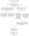
Fig. 2 is a flowchart of a control method for an energy storage system provided by an embodiment of the present application; -
Fig. 3 is a flowchart of a control method for an energy storage system provided by another embodiment of the present application; -
Fig. 4 is a structural view of a control apparatus for an energy storage system provided by an embodiment of the present application; -
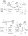
Fig. 5 is a schematic structural view of an energy storage system provided by an embodiment of the present application; -
Fig. 6 is a schematic view showing an energy flow direction when an energy storage system provided by an embodiment of the present application is in a first working mode; -
Fig. 7 is a schematic view showing an energy flow direction when an energy storage system provided by an embodiment of the present application is in a second working mode; -
Fig. 8 is a schematic view showing an energy flow direction when an energy storage system provided by an embodiment of the present application is in a third working mode. - In order to make the purpose, technical solution and advantages of the present application more explicit, the technical solution of the present application will be described in detail below in conjunction with the accompanying drawings and embodiments. Obviously, the embodiments described are only some embodiments of the present application, not all of the embodiments. Based on the embodiments of the present application, all other embodiments obtained by those of ordinary skills in the art on the premise that no inventive effort is involved pertain to the protection scope of the present application.
- It is to be noted that, the charge-discharge controller mentioned in the embodiments of the present application is a bidirectional DC/DC controller with CPU, the grid on-off controller is a DC/AC controller with CPU, and the energy storage battery is provided with a battery management system BMS, wherein the DC/AC controller may not only convert a direct current into an alternating current, but also convert the alternating current into the direct current.
- Referring to
Fig. 2 , the embodiment of the present application provides a control method for an energy storage system, wherein the control method comprising: obtaining an operation parameter of a power grid and an electric quantity state of an energy storage battery in the energy storage system; and controlling working states of the power grid, the energy storage battery, a first auxiliary power supply and a second auxiliary power supply according to the operation parameter of the power grid and the electric quantity state of the energy storage battery. - In the control method for an energy storage system provided by the embodiment of the present application, first of all, the operation parameter of the power grid and the electric quantity state of the energy storage battery in the energy storage system are obtained; and then, the working states of the power grid, the energy storage battery, the first auxiliary power supply and the second auxiliary power supply are controlled according to the operation parameter of the power grid and the electric quantity state of the energy storage battery. In the solution of the present application, the operation parameter of the power grid and the electric quantity state of the energy storage battery are considered during the control, so that it is possible to avoid the situation of over-discharge of the battery due to supplying power still to the load when the power grid is cut off and the electric quantity of the energy storage battery is low. By considering the operation parameter of the power grid and the electric quantity state of the energy storage battery, the service life of the energy storage battery can be prolonged, and the user experience can be ensured. It is to be noted that, the control method for the energy storage system may be performed by a control apparatus for the energy storage system, a control chip in the energy storage system, or a processor not comprised in a computer device.
- In an embodiment of the present application, the operation parameter of the power grid comprises: a current, a voltage and frequency information of the power grid. The electric quantity state of the energy storage battery comprises a state of sufficient electric quantity and a state of insufficient electric quantity. When the electric quantity of the energy storage battery is sufficient, the energy storage battery satisfies a discharge condition. When the electric quantity of the energy storage battery is insufficient, the energy storage battery does not satisfy the discharge condition.
- In an embodiment of the present application, as shown in
Fig. 3 , in the control method for an energy storage system according to the embodiment of the present application, the controlling of the working states of the power grid, the energy storage battery, the first auxiliary power supply and the second auxiliary power supply according to the operation parameter of the power grid and the electric quantity state of the energy storage battery comprises the following step. - Whether the power grid operates normally is determined according to the current, the voltage and the frequency information of the power grid.
- When the power grid operates normally, the power grid is controlled to be connected to the energy storage system, the first auxiliary power supply is controlled to work, and the second auxiliary power supply is controlled not to work, and whether an electric quantity of the energy storage battery is sufficient is determined according to the electric quantity state of the energy storage battery.
- In the embodiment, whether the power grid operates normally is determined according to the obtained current, voltage and frequency information of the power grid. When the power grid operates normally, the power grid is controlled to be connected to the energy storage system so as to supply power to the load; the first auxiliary power supply is controlled to work so as to supply power to the entire energy storage system, and the second auxiliary power supply is controlled not to work; and the working state of the energy storage battery is further controlled according to the electric quantity condition.
- In an embodiment of the present application, when the power grid operates normally, the control method for the energy storage system further comprises: controlling the energy storage battery to be disconnected from the energy storage system when the electric quantity of the energy storage battery is sufficient; and controlling the energy storage battery to be connected to the energy storage system when the electric quantity of the energy storage battery is insufficient.
- In the embodiment, when the electric quantity of the energy storage battery is sufficient, there is no need to charge the energy storage battery at this time, and the energy storage battery is controlled to be disconnected from the energy storage system. When the electric quantity of the energy storage battery is insufficient, the energy storage battery is controlled to be connected to the energy storage system, so that the energy storage system charges the energy storage battery.
- In an embodiment of the present application, the control method for the energy storage system further comprises: when the power grid operates abnormally, controlling the power grid to be disconnected from the energy storage system, controlling the first auxiliary power supply not to work, and determining, according to the electric quantity state of the energy storage battery, whether an electric quantity of the energy storage battery is sufficient.
- When the power grid is abnormal, the energy storage system is controlled to be disconnected from the power grid. Since the first auxiliary power supply is provided to intake power from the power grid, the first auxiliary power supply is controlled not to work at this time, and whether the electric quantity of the energy storage battery is sufficient is further determined according to the electric quantity state of the energy storage battery.
- In an embodiment of the present application, when the power grid operates abnormally, the control method for the energy storage system further comprises: when the electric quantity of the energy storage battery is sufficient, controlling the energy storage battery to be connected to the energy storage system, and controlling the second auxiliary power supply to work; and controlling the energy storage battery to be disconnected from the energy storage system when the electric quantity of the energy storage battery does not satisfy a discharge condition.
- In the embodiment, when the electric quantity of the energy storage battery is sufficient, the energy storage battery is controlled to be connected to the energy storage system so that the energy storage battery supplies power to the load, and the second auxiliary power supply is controlled to work so as to supply power to the energy storage system. When the electric quantity of the energy storage battery does not satisfy the discharge condition, the energy storage battery is controlled to be disconnected from the energy storage system, the load is controlled to be disconnected from the energy storage system, and the second auxiliary power supply, the charge-discharge controller and the grid on-off controller are controlled to operate in a low power consumption mode. In this way, there will not be the situation of over-discharge of the battery due to supplying power still to the load when the power grid is cut off and the electric quantity of the energy storage battery is low. By considering the operation parameter of the power grid and the electric quantity state of the energy storage battery, the service life of the energy storage battery can be prolonged, and the user experience can be ensured.
- It is to be noted that, the energy storage battery does not satisfy the discharge condition, which means that it is possible to lead to over-discharge of the energy storage battery if the current energy storage battery continues to discharge.
- In the specific control method for the energy storage system provided by the embodiment of the present application, working of the first auxiliary power supply or working of the second auxiliary power supply or the low power consumption mode may be selected according to the working state of the energy storage system, so as to minimize the discharge amount of the energy storage battery when not in use, prolong its service time and avoid over-discharge, thereby reducing the after-sales maintenance cost and improving the client experience.
- In an embodiment of the present application, as shown in
Fig. 4 , a control apparatus for an energy storage system is also provided. The control apparatus comprises adata obtaining module 41 and adevice control module 42. - The
data obtaining module 41 is configured to obtain an operation parameter of a power grid and an electric quantity state of an energy storage battery in the energy storage system. The obtained operation parameter of the power grid in the energy storage system comprise: a obtained current, a voltage and frequency information of the power grid. Whether the power grid is abnormal is determined according to the current, voltage and frequency information. - The
device control module 42 is configured to control working states of the power grid, the energy storage battery, a first auxiliary power supply and a second auxiliary power supply according to the operation parameter of the power grid and the electric quantity state of the energy storage battery. Specifically, whether the power grid operates normally is determined according to the current, the voltage and the frequency information of the power grid. When the power grid operates normally, the power grid is controlled to be connected to the energy storage system, the first auxiliary power supply is controlled to work, the second auxiliary power supply is controlled not to work, and whether an electric quantity of the energy storage battery is sufficient is determined according to the electric quantity state of the energy storage battery. When the electric quantity of the energy storage battery is sufficient, the energy storage battery is controlled to be disconnected from the energy storage system; when the electric quantity of the energy storage battery is insufficient, the energy storage battery is controlled to be connected to the energy storage system, so that the energy storage system charges the energy storage battery. - When the power grid operates abnormally, the power grid is controlled to be disconnected from the energy storage system, and the first auxiliary power supply is controlled not to work, and whether the electric quantity of the energy storage battery is sufficient is determined according to the electric quantity state of the energy storage battery. When the electric quantity of the energy storage battery is sufficient, the energy storage battery is controlled to be connected to the energy storage system, so that the energy storage battery supplies power to the load and the second auxiliary power supply is controlled to work. When the electric quantity of the energy storage battery does not satisfy the discharge condition, the energy storage battery is controlled to be disconnected from the energy storage system. When the electric quantity of the energy storage battery does not satisfy the discharge condition, the load is controlled to be disconnected from the energy storage system, and the second auxiliary power supply, a charge-discharge controller and a grid on-off controller are controlled to operate in a low power consumption mode.
- In the control apparatus for an energy storage system provided by the embodiment of the present application, working of the first auxiliary power supply or working of the second auxiliary power supply or the low power consumption mode may be selected according to the working state of the energy storage system, so as to minimize the discharge amount of the energy storage battery when not in use, prolong its service time, and avoid over-discharge, thereby reducing the after-sales maintenance cost and improving the client experience.
- In an embodiment, as shown in
Fig. 5 , the present application also provides an energy storage system, the energy storage system comprising: anenergy storage battery 1, a charge-discharge controller DC/DC, a grid on-off controller DC/AC, apower grid 2, aload 5, a firstauxiliary power supply 3, a second auxiliary power supply 4, and a control apparatus for an energy storage system provided in the above-described embodiment of the application. - The
energy storage battery 1 is connected to the charge-discharge controller DC/DC and the grid on-off controller DC/AC sequentially. - The grid on-off controller DC/AC is connected to the
power grid 2 and theload 5 respectively. - The first
auxiliary power supply 3 is connected to thepower grid 2, the charge-discharge controller DC/DC and the grid on-off controller DC/AC respectively. - The second auxiliary power supply 4 is connected to the
energy storage battery 1, the charge-discharge controller DC/DC and the grid on-off controller DC/AC respectively. - In an embodiment, as shown in
Fig. 5 , the energy storage system comprises an energy storage battery (with a battery management system BMS), a charge-discharge controller (bidirectional DC/DC), a grid on-off controller (DC/AC), alternating current relays K3, K4, K5, K6, direct current contactors K1, K2, a first auxiliary power supply, a second auxiliary power supply, a power grid and a load. The direct current contactors K1 and K2 are connected between the energy storage battery and the charge-discharge controller DC/DC, the alternating current relays K3 and K4 are connected between the grid on-off controller DC/AC and the power grid, and the alternating current relays K5 and K6 are connected between the grid on-off controller DC/AC and the load. The first auxiliary power supply intakes power from the alternating current power grid and outputs the power to BMS of the energy storage battery, the charge-discharge controller DC/DC and the grid on-off controller DC/AC. The second auxiliary power supply intakes power from the energy storage battery side and outputs the power to the BMS of the energy storage battery, the charge-discharge controller DC/DC and the grid on-off controller DC/AC. The charge-discharge controller DC/DC may output controller signals CH1 and CH2 to control whether the first auxiliary power supply and the second auxiliary power supply work. Similarly, the controller signals CH1 and CH2 may also be output by the grid on-off controller DC/AC, and one of them may be selected in practical application. - The specific working process is as follows:
Working modes of the energy storage system may be divided into four working modes. In a first working mode, the power grid supplies power to the load, and the relays K3, K4, K5 and K6 are closed. In a second working mode, the power grid supplies power to the load and charges the energy storage battery at the same time, and at this time, the relays K3, K4, K5 and K6 and the contactors K1 and K2 are all closed. In a third working mode, the power grid is abnormal, the energy of the energy storage battery satisfies a discharge condition, and the energy storage battery supplies power to the load, and the relays K5 and K6 are closed, the contactors K1 and K2 are closed, and the relays K3 and K4 are open. In a fourth working mode, the power grid is abnormal, the energy of the energy storage battery does not satisfy the discharge condition, and the charge-discharge controller and the grid on-off controller work in the low power consumption mode, and the relays K3, K4, K5 and K6 and the contactors K1 and K2 are all open. - When the energy storage system is in the first working mode, as shown in
Fig. 6 , the power grid is normal, the first auxiliary power supply starts to work and supplies power to the entire energy storage system, and the control signal CH2 controls the second auxiliary power supply not to work. At this time, the energy storage battery does not discharge, and energy flows from the power grid to the load. - When the energy storage system is in the second working mode, as shown in
Fig. 7 , the power grid is normal, the first auxiliary power supply starts to work and supplies power to the entire energy storage system, and the control signal CH2 controls the second auxiliary power supply not to work. At this time, the energy storage battery is in a charging state, and energy flows from the power grid to the load and the energy storage battery. - When the energy storage system is in the third working mode, as shown in
Fig. 8 , the power grid is abnormal, the first auxiliary power supply does not work, the control signal CH2 controls the second auxiliary power supply to start working, and the second auxiliary power supply supplies power to the entire energy storage system, and the energy storage system is in an off-grid working state, and energy flows from the energy storage battery to the load. - When the energy storage system is in the fourth working mode, the power grid is abnormal, the electric quantity state of the energy storage battery does not satisfy the discharge condition, the first auxiliary power supply does not work, the control signal CH2 controls the second auxiliary power supply to start working, and the second auxiliary power supply supplies power to the entire energy storage system. At this time, the relays and the contactors are open, and the second auxiliary power supply, the charge-discharge controller and the grid on-off controller operate in the low power consumption mode, which greatly reduces the discharge amount of the energy storage battery, prolongs the standby time of the energy storage battery waiting to be charged.
- In the energy storage system provided by the embodiment of the present application, working of the first auxiliary power supply or working of the second auxiliary power supply or the low power consumption mode may be selected according to the working state of the energy storage system, so as to minimize the discharge amount of the energy storage battery when not in use, prolong its service time and avoid over-discharge, thereby reducing the after-sales maintenance cost and improving the client experience.
- In an embodiment, the present application provides an energy storage device, the energy storage device comprising the energy storage system provided in the above-described embodiment.
- The energy storage device provided by the embodiment of the present application, based on an architecture of the energy storage system consisting of an energy storage battery, a charge-discharge controller (bidirectional DC/DC), a grid on-off controller DC/AC and a load, selects a corresponding auxiliary power supply method according to different working modes of the system, so as to solve the problem of fast discharge or over-discharge of the energy storage battery.
- It may be understood that, for the same or similar parts in the above-described embodiments, reference may be made to each other, and for the content not explained in detail in some embodiments, reference may be made to the same or similar content in other embodiments.
- It is to be noted that, in the description of the present application, the terms such as "first" and "second" which are only for illustrative purposes, shall not be understood as indicating or implying relative importance. In addition, in the description of the present application, "a plurality of" means at least two unless specified otherwise.
- Any process or method description in the flowchart or otherwise described here may be understood as representing a module, segment or part of a code that comprises one or more executable instructions for implementing specific logical functions or process steps, and the scope of preferred embodiments of the present application comprises additional implementations, wherein functions may be performed not according to the sequence shown or discussed, comprising a substantially simultaneous manner or a reversed sequence according to the functions involved, which should be understood by those skilled in the technical field to which the embodiments of the present application belong.
- It should be understood that various parts of the present application may be implemented in hardware, software, firmware or a combination thereof. In the above-described embodiments, a plurality of steps or methods may be realized by software or firmware stored in a memory and performed by an appropriate instruction execution system. For example, if implemented in hardware, as in another embodiment, it may be implemented by any of the following technologies commonly known in this field or a combination thereof: a discrete logic circuit with a logic gate circuit for realizing a logic function on a data signal, an application specific integrated circuit with a suitable combinational logic gate circuit, a programmable gate array (PGA), a field programmable gate array (FPGA), or the like.
- Those skilled in the art may understand that all or some of the steps carried by the method of the above-described embodiments may be accomplished by instructing related hardware by a program. The program may be stored in a computer-readable storage medium, and the program, when executed, comprises one of the steps of the method embodiments or a combination thereof.
- In addition, various functional units in each embodiment of the present application may be integrated in one processing module, or each unit may be physically present alone, or two or more units may be integrated in one module. The above-described integrated modules may be realized in the form of hardware, or realized in the form of functional modules of software. The integrated module may also be stored in a computer-readable storage medium if implemented in the form of functional modules of software and sold or used as an independent product.
- The storage medium mentioned above may be a read-only memory, a magnetic disk or an optical disk, etc.
- In the description of the specification, descriptions referring to the terms such as "one embodiment", "some embodiments", "an example", "a specific example" or "some examples" mean that specific features, structures, materials or characteristics described in conjunction with the embodiment or example are comprised in at least one embodiment or example of the present application. In the specification, the schematic expressions of the above-described terms do not necessarily refer to the same embodiment or example. Moreover, the specific features, structures, materials or characteristics described may be combined in a suitable manner in any one or more embodiments or examples.
- Although the embodiments of the present application have been shown and described above, it may be understood that the above-described embodiments are exemplary and cannot be understood as limiting the present application, and those skilled in the art may make changes, modifications, substitutions and variations to the above-described embodiments within the scope of the present application.
Claims (10)
- A control method for an energy storage system, comprising:obtaining an operation parameter of a power grid and an electric quantity state of an energy storage battery in the energy storage system; andcontrolling working states of the power grid, the energy storage battery, a first auxiliary power supply and a second auxiliary power supply according to the operation parameter of the power grid and the electric quantity state of the energy storage battery.
- The method according to claim 1, wherein the operation parameter of the power grid comprises: a current, a voltage and frequency information of the power grid.
- The method according to claim 2, wherein the controlling of the working states of the power grid, the energy storage battery, the first auxiliary power supply and the second auxiliary power supply according to the operation parameter of the power grid and the electric quantity state of the energy storage battery comprises:determining whether the power grid operates normally according to the current, the voltage and the frequency information of the power grid; andwhen the power grid operates normally, controlling the power grid to be connected to the energy storage system, controlling the first auxiliary power supply to work, controlling the second auxiliary power supply not to work, and determining, according to the electric quantity state of the energy storage battery, whether an electric quantity of the energy storage battery is sufficient.
- The method according to claim 3, further comprising:controlling the energy storage battery to be disconnected from the energy storage system when the electric quantity of the energy storage battery is sufficient; andcontrolling the energy storage battery to be connected to the energy storage system when the electric quantity of the energy storage battery is insufficient.
- The method according to claim 2, wherein the controlling of the working states of the power grid, the energy storage battery, the first auxiliary power supply and the second auxiliary power supply according to the operation parameter of the power grid and the electric quantity state of the energy storage battery comprises:determining whether the power grid operates normally according to the current, the voltage and the frequency information of the power grid; andwhen the power grid operates abnormally, controlling the power grid to be disconnected from the energy storage system, controlling the first auxiliary power supply not to work, and determining, according to the electric quantity state of the energy storage battery, whether an electric quantity of the energy storage battery is sufficient.
- The method according to claim 5, further comprising:when the electric quantity of the energy storage battery is sufficient, controlling the energy storage battery to be connected to the energy storage system, and controlling the second auxiliary power supply to work; andcontrolling the energy storage battery to be disconnected from the energy storage system when the electric quantity of the energy storage battery does not satisfy a discharge condition.
- The method according to claim 6, further comprising:
when the electric quantity of the energy storage battery does not satisfy the discharge condition, controlling a load to be disconnected from the energy storage system, and controlling the second auxiliary power supply, a charge-discharge controller and a grid on-off controller to operate in a low power consumption mode. - A control apparatus for an energy storage system, comprising:a data obtaining module (41) configured to obtain an operation parameter of a power grid and an electric quantity state of an energy storage battery in the energy storage system; anda device control module (42) configured to control working states of the power grid, the energy storage battery, a first auxiliary power supply and a second auxiliary power supply according to the operation parameter of the power grid and the electric quantity state of the energy storage battery.
- An energy storage system, comprising: an energy storage battery (1), a charge-discharge controller (DC/DC), a grid on-off controller (DC/AC), a power grid (2), a load (5), a first auxiliary power supply (3), a second auxiliary power supply (4) and the control apparatus according to claim 8;wherein the energy storage battery (1) is connected to the charge-discharge controller (DC/DC) and the grid on-off controller (DC/AC) sequentially;the grid on-off controller (DC/AC) is connected to the power grid (2) and the load (5);the first auxiliary power supply (3) is connected to the power grid (2), the charge-discharge controller (DC/DC) and the grid on-off controller (DC/AC); andthe second auxiliary power supply (4) is connected to the energy storage battery (1), the charge-discharge controller (DC/DC) and the grid on-off controller (DC/AC).
- An energy storage device, comprising: the energy storage system according to claim 9.
Applications Claiming Priority (2)
| Application Number | Priority Date | Filing Date | Title |
|---|---|---|---|
| CN202111052847.0A CN113922440A (en) | 2021-09-06 | 2021-09-06 | Energy storage system control method and device, energy storage system and energy storage equipment |
| PCT/CN2022/091645 WO2023029552A1 (en) | 2021-09-06 | 2022-05-09 | Energy storage system control method and apparatus, energy storage system, and energy storage device |
Publications (2)
| Publication Number | Publication Date |
|---|---|
| EP4401270A1 true EP4401270A1 (en) | 2024-07-17 |
| EP4401270A4 EP4401270A4 (en) | 2024-12-25 |
Family
ID=79234288
Family Applications (1)
| Application Number | Title | Priority Date | Filing Date |
|---|---|---|---|
| EP22862695.8A Pending EP4401270A4 (en) | 2021-09-06 | 2022-05-09 | Energy storage system control method and apparatus, energy storage system, and energy storage device |
Country Status (5)
| Country | Link |
|---|---|
| US (1) | US12341343B2 (en) |
| EP (1) | EP4401270A4 (en) |
| CN (1) | CN113922440A (en) |
| AU (1) | AU2022337487A1 (en) |
| WO (1) | WO2023029552A1 (en) |
Families Citing this family (6)
| Publication number | Priority date | Publication date | Assignee | Title |
|---|---|---|---|---|
| CN113922440A (en) | 2021-09-06 | 2022-01-11 | 珠海格力电器股份有限公司 | Energy storage system control method and device, energy storage system and energy storage equipment |
| CN115579929B (en) * | 2022-11-21 | 2023-05-05 | 成都特隆美储能技术有限公司 | Control method for improving battery protection of energy storage system |
| CN116317180B (en) * | 2023-05-22 | 2023-09-22 | 宁德时代新能源科技股份有限公司 | Energy storage device and control method thereof |
| CN116990701B (en) * | 2023-09-27 | 2023-12-22 | 南通中集元能集成科技有限公司 | Energy storage test system and energy storage battery performance test method |
| CN120033790A (en) * | 2023-11-23 | 2025-05-23 | 佛山市顺德区美的电子科技有限公司 | Battery control method, control device, light storage system and storage medium |
| CN117621891B (en) * | 2024-01-25 | 2024-06-11 | 杭州闪充聚能新能源有限公司 | Vehicle charging system and energy storage device |
Family Cites Families (11)
| Publication number | Priority date | Publication date | Assignee | Title |
|---|---|---|---|---|
| US9577430B2 (en) * | 2010-08-20 | 2017-02-21 | Lg Electronics Inc. | Electronic device and method of controlling power supply therein |
| EP2738902B1 (en) * | 2011-07-26 | 2016-07-06 | Kyocera Corporation | Power supply system, distribution device, and power control device |
| CN105109358B (en) * | 2015-09-22 | 2018-05-11 | 奇瑞汽车股份有限公司 | A kind of wireless charging system for electric automobile |
| CN106712090A (en) * | 2017-01-20 | 2017-05-24 | 合肥聚能新能源科技有限公司 | Modular photovoltaic energy-storage inverter |
| US20190081479A1 (en) * | 2017-09-11 | 2019-03-14 | Outback Power Technologies, Inc. | Configuration systems and methods for power control systems |
| CN209448499U (en) * | 2019-01-10 | 2019-09-27 | 上能电气股份有限公司 | A kind of secondary power system and photovoltaic inverting system of photovoltaic inverting system |
| CN113131462B (en) * | 2020-01-10 | 2025-04-25 | 台达电子企业管理(上海)有限公司 | AC load power supply system and method |
| CN111463877A (en) * | 2020-05-06 | 2020-07-28 | 东莞龙升电子有限公司 | Charging and discharging circuit, control method and control unit |
| CN112737086A (en) * | 2020-12-14 | 2021-04-30 | 珠海格力电器股份有限公司 | Information cabinet control method and device, information cabinet, storage medium and processor |
| CN112821435B (en) | 2020-12-31 | 2024-03-22 | 珠海格力电器股份有限公司 | Off-grid scheduling method and device and energy storage power supply system |
| CN113922440A (en) | 2021-09-06 | 2022-01-11 | 珠海格力电器股份有限公司 | Energy storage system control method and device, energy storage system and energy storage equipment |
-
2021
- 2021-09-06 CN CN202111052847.0A patent/CN113922440A/en active Pending
-
2022
- 2022-05-09 EP EP22862695.8A patent/EP4401270A4/en active Pending
- 2022-05-09 AU AU2022337487A patent/AU2022337487A1/en active Pending
- 2022-05-09 US US18/567,954 patent/US12341343B2/en active Active
- 2022-05-09 WO PCT/CN2022/091645 patent/WO2023029552A1/en not_active Ceased
Also Published As
| Publication number | Publication date |
|---|---|
| EP4401270A4 (en) | 2024-12-25 |
| WO2023029552A1 (en) | 2023-03-09 |
| AU2022337487A1 (en) | 2023-12-14 |
| CN113922440A (en) | 2022-01-11 |
| US12341343B2 (en) | 2025-06-24 |
| US20240275169A1 (en) | 2024-08-15 |
Similar Documents
| Publication | Publication Date | Title |
|---|---|---|
| EP4401270A1 (en) | Energy storage system control method and apparatus, energy storage system, and energy storage device | |
| CN109120051B (en) | Multi-channel mixed battery manager, control method of lithium battery power supply unit and base station | |
| WO2022051902A1 (en) | Low-voltage battery charging system and method | |
| WO2021031742A1 (en) | Power supply control method, apparatus and system | |
| WO2023216483A1 (en) | Energy storage system control method and apparatus, device, storage medium, and program product | |
| CN111355252B (en) | A distributed energy storage system and charging and discharging method thereof | |
| TW201443794A (en) | Large electric vehicle power supply structure and battery box rotation control method thereof | |
| CN110661278A (en) | Energy storage air conditioning system and control method and control device thereof | |
| WO2023082598A1 (en) | Working mode switching control method and device for vehicle-mounted charger, and vehicle-mounted charger | |
| CN116231787A (en) | A charging and discharging control method, device, terminal equipment and storage medium | |
| CN117394496A (en) | Standby control method of energy storage inverter and related equipment | |
| CN115133625A (en) | Charging control method, device, equipment and storage medium | |
| WO2024160299A1 (en) | Power circuit and working machine | |
| US20240222986A1 (en) | Power supply control method and power supply control circuit | |
| CN112640247A (en) | Power supply management equipment and control method | |
| WO2016082514A1 (en) | Control method, device and electronic apparatus | |
| US20230030030A1 (en) | Charging and discharging switching apparatus and method, and bidirectional charging system | |
| CN116766931A (en) | Vehicle battery management system, data acquisition method and device and vehicle | |
| CN103915891A (en) | Power supply system and method | |
| CN116247771A (en) | An inverter-activated lithium battery device with protection function and its control method | |
| CN110707679B (en) | Voltage control method, photovoltaic power supply device and system | |
| US12483062B2 (en) | Uninterruptible power supply, uninterruptible power supply control method, related apparatus, and system | |
| CN210430931U (en) | Energy storage air conditioning system | |
| CN114765377A (en) | Voltage balancing system with multiple batteries connected in series | |
| CN114578239A (en) | Method and device for testing battery capacity of uninterruptible power supply |
Legal Events
| Date | Code | Title | Description |
|---|---|---|---|
| STAA | Information on the status of an ep patent application or granted ep patent |
Free format text: STATUS: THE INTERNATIONAL PUBLICATION HAS BEEN MADE |
|
| PUAI | Public reference made under article 153(3) epc to a published international application that has entered the european phase |
Free format text: ORIGINAL CODE: 0009012 |
|
| STAA | Information on the status of an ep patent application or granted ep patent |
Free format text: STATUS: REQUEST FOR EXAMINATION WAS MADE |
|
| 17P | Request for examination filed |
Effective date: 20231205 |
|
| AK | Designated contracting states |
Kind code of ref document: A1 Designated state(s): AL AT BE BG CH CY CZ DE DK EE ES FI FR GB GR HR HU IE IS IT LI LT LU LV MC MK MT NL NO PL PT RO RS SE SI SK SM TR |
|
| DAV | Request for validation of the european patent (deleted) | ||
| DAX | Request for extension of the european patent (deleted) | ||
| A4 | Supplementary search report drawn up and despatched |
Effective date: 20241125 |
|
| RIC1 | Information provided on ipc code assigned before grant |
Ipc: H02J 9/06 20060101ALI20241119BHEP Ipc: H02J 3/32 20060101ALI20241119BHEP Ipc: H02J 7/02 20160101ALI20241119BHEP Ipc: H02J 7/34 20060101ALI20241119BHEP Ipc: H02J 7/00 20060101AFI20241119BHEP |