EP4401249A1 - Connector assembly - Google Patents
Connector assembly Download PDFInfo
- Publication number
- EP4401249A1 EP4401249A1 EP24151654.1A EP24151654A EP4401249A1 EP 4401249 A1 EP4401249 A1 EP 4401249A1 EP 24151654 A EP24151654 A EP 24151654A EP 4401249 A1 EP4401249 A1 EP 4401249A1
- Authority
- EP
- European Patent Office
- Prior art keywords
- connector
- mating connector
- axis
- nut
- coupling
- Prior art date
- Legal status (The legal status is an assumption and is not a legal conclusion. Google has not performed a legal analysis and makes no representation as to the accuracy of the status listed.)
- Pending
Links
Images




Classifications
-
- H—ELECTRICITY
- H01—ELECTRIC ELEMENTS
- H01R—ELECTRICALLY-CONDUCTIVE CONNECTIONS; STRUCTURAL ASSOCIATIONS OF A PLURALITY OF MUTUALLY-INSULATED ELECTRICAL CONNECTING ELEMENTS; COUPLING DEVICES; CURRENT COLLECTORS
- H01R13/00—Details of coupling devices of the kinds covered by groups H01R12/70 or H01R24/00 - H01R33/00
- H01R13/62—Means for facilitating engagement or disengagement of coupling parts or for holding them in engagement
- H01R13/629—Additional means for facilitating engagement or disengagement of coupling parts, e.g. aligning or guiding means, levers, gas pressure electrical locking indicators, manufacturing tolerances
- H01R13/631—Additional means for facilitating engagement or disengagement of coupling parts, e.g. aligning or guiding means, levers, gas pressure electrical locking indicators, manufacturing tolerances for engagement only
-
- H—ELECTRICITY
- H01—ELECTRIC ELEMENTS
- H01R—ELECTRICALLY-CONDUCTIVE CONNECTIONS; STRUCTURAL ASSOCIATIONS OF A PLURALITY OF MUTUALLY-INSULATED ELECTRICAL CONNECTING ELEMENTS; COUPLING DEVICES; CURRENT COLLECTORS
- H01R13/00—Details of coupling devices of the kinds covered by groups H01R12/70 or H01R24/00 - H01R33/00
- H01R13/62—Means for facilitating engagement or disengagement of coupling parts or for holding them in engagement
- H01R13/621—Bolt, set screw or screw clamp
- H01R13/6215—Bolt, set screw or screw clamp using one or more bolts
-
- H—ELECTRICITY
- H01—ELECTRIC ELEMENTS
- H01R—ELECTRICALLY-CONDUCTIVE CONNECTIONS; STRUCTURAL ASSOCIATIONS OF A PLURALITY OF MUTUALLY-INSULATED ELECTRICAL CONNECTING ELEMENTS; COUPLING DEVICES; CURRENT COLLECTORS
- H01R13/00—Details of coupling devices of the kinds covered by groups H01R12/70 or H01R24/00 - H01R33/00
- H01R13/62—Means for facilitating engagement or disengagement of coupling parts or for holding them in engagement
- H01R13/639—Additional means for holding or locking coupling parts together, after engagement, e.g. separate keylock, retainer strap
- H01R13/6395—Additional means for holding or locking coupling parts together, after engagement, e.g. separate keylock, retainer strap for wall or panel outlets
-
- H—ELECTRICITY
- H01—ELECTRIC ELEMENTS
- H01R—ELECTRICALLY-CONDUCTIVE CONNECTIONS; STRUCTURAL ASSOCIATIONS OF A PLURALITY OF MUTUALLY-INSULATED ELECTRICAL CONNECTING ELEMENTS; COUPLING DEVICES; CURRENT COLLECTORS
- H01R2201/00—Connectors or connections adapted for particular applications
- H01R2201/26—Connectors or connections adapted for particular applications for vehicles
Definitions
- the present description relates to the field of electrical connectors, notably to the field of electrical power connectors.
- This type of connector can be used in motor vehicles, for example.
- the present description notably relates to a connector assembly comprising a connector and a mating connector, with one from among the connector and the mating connector being a male connector and the other one from among the connector and the mating connector being a female connector.
- Such a connector assembly prefferably be equipped with a coupling system allowing the connector and the mating connector to be mechanically coupled, or assembled, into a final coupling position assuring electrical connection of the connector and of the mating connector.
- the coupling system can facilitate the physical effort required to connect the connector and the mating connector.
- a first known coupling system comprises a pivoting component, such as a lever, pivotably mounted on one from among the connector and the mating connector, for example, the connector.
- a pivoting component such as a lever
- the lever In order to couple and connect the connector and the mating connector, they are pre-coupled and then the lever is manually turned from a deployed position to a retracted position, causing the connector to approach the mating connector by a translation movement in a coupling direction perpendicular to the pivot axis of the lever.
- a second known coupling system comprises a component that is slidably mounted on one from among the connector and the mating connector, for example, on the connector, with the sliding component being arranged to cooperate with ramps.
- the connector and the mating connector are pre-coupled and then the sliding component is manually slid from a deployed position to a retracted position, which causes, via the ramps, the connector to approach the mating connector by a translation movement in a coupling direction perpendicular to a sliding plane.
- a third known coupling system comprises a screw mounted on one from among the connector and the mating connector and a nut mounted on the other one from among the connector and the mating connector.
- the connector and the mating connector are pre-coupled and then the screw is screwed into the nut using a screwing tool, causing the connector and the mating connector to approach each other by a translation movement in a coupling direction parallel to the screwing axis.
- the connector and the mating connector can be connected during or at the end of manufacturing in an environment that is likely to be congested. Access to the connectors can be limited and coupling the connectors can be hindered by obstacles.
- the connector and the mating connector may need to be disconnected and then reconnected, for example, for maintenance or repair. This requires free, unobstructed access to the connectors and sufficient space in the vicinity of the connectors in order to allow an operator to manually uncouple and/or couple the connector and the mating connector.
- Coupling systems using a lever or a sliding component are relatively bulky since the lever or the sliding component occupy a considerable amount of space, notably in the deployed position and/or when they are actuated.
- the lever or the sliding component In order for an operator to be able to couple the connectors, access needs to be provided to the lever or to the sliding component and sufficient space needs to be left in the vicinity of the connector supporting the lever or the sliding component in order to be able to operate it manually.
- the screw and nut coupling system is less bulky but has the disadvantage of requiring a free space outside the connector in the vicinity of the screw head, along the screwing axis, in order to place a screwing tool therein and couple it with the screw head.
- certain environmental constraints can limit close access to the connector along the screwing axis in order to place a screwing tool therein.
- An aim of the present disclosure is to address the aforementioned disadvantages of the prior art and notably to adapt the screw-nut type coupling system in accordance with imposed environmental constraints.
- the present description relates to a connector assembly comprising a connector and a mating connector, said connector and said mating connector being arranged in order to be coupled together by means of a coupling system comprising a nut and a threaded rod, so as to electrically connect the connector and the mating connector, with one from among the nut and the threaded rod being rotatably mounted on one from among the connector and the mating connector and the other one from among the nut and the threaded rod being fixedly mounted on the other one from among the connector and the mating connector, said assembly comprising a device for driving the coupling system, comprising a drive shaft and a gear system arranged in order to transmit a rotational movement of the drive shaft, rotated about an axis of rotation, to the rotary element of the coupling system, rotated about a screwing axis, with the axis of rotation of the drive shaft and the screwing axis of the rotary element of the coupling system being non-parallel.
- a coupling system comprising
- the drive device allows the direction of rotation to be changed in order to rotate the rotary element of the coupling system, namely the nut or the threaded rod: the drive shaft is rotated about an axis of rotation, which rotates the nut, or the threaded rod, about a screwing axis; however, the axis of rotation of the shaft is different and not parallel to the screwing axis.
- the axis of rotation, or a projection of the axis of rotation in a plane containing the screwing axis is separated from the screwing axis by an angle that is strictly greater than 0° and is strictly less than 180°.
- the nut or the threaded rod can be screwed using a screwing tool oriented in a different direction from that of the screwing axis. This allows the connector and the mating connector to be coupled in a way that adapts to imposed environmental constraints.
- the gear system is a bevel gear system.
- a worm wheel drive device could be used.
- said gear system comprises a driving gearwheel supported by the drive shaft and a driven gearwheel supported by the rotary element of the coupling system.
- the two gearwheels can have the same diameter.
- the diameter of the gearwheel supported by the drive shaft is greater than that of the gearwheel supported by the rotary element of the coupling system. This reduces the force required to turn the nut or the threaded rod.
- the axis of rotation or a projection of the axis of rotation in a plane comprising the screwing axis, is oriented at 90° to the screwing axis.
- the connector assembly can comprise two access passages provided to leave free access to the two ends of the drive shaft.
- said connector or mating connector is adapted to provide two external accesses, respectively at the two ends of the drive shaft, for example, from two opposite sides of said connector or mating connector.
- Said connector or mating connector is advantageously free of obstructions between the ends of the drive shaft and the outside of the connector or mating connector.
- This provides significant access flexibility for coupling or uncoupling the connector and the mating connector.
- a motor vehicle manufacturer may wish to have access to the connector assembly from above the vehicle, when manufacturing the vehicle, and then from below the vehicle, when repairing or maintaining the vehicle.
- the possibility of rotating the drive shaft by its two opposite ends provides significant access flexibility for coupling the connector and the mating connector.
- each of the two ends of the drive shaft is provided with means for coupling to a rotary drive tool.
- the connector assembly comprises a coupling assurance device comprising a locking component rotatably mounted on the rotary element of the coupling system, mounted on one from among the connector and the mating connector, said locking component comprising at least one locking finger arranged to be introduced, by rotating about the screwing axis, into a notch provided in the other one from among the connector and the mating connector, in a final coupling position of the connector and of the mating connector, so as to assure and lock said final coupling position.
- a coupling assurance device comprising a locking component rotatably mounted on the rotary element of the coupling system, mounted on one from among the connector and the mating connector, said locking component comprising at least one locking finger arranged to be introduced, by rotating about the screwing axis, into a notch provided in the other one from among the connector and the mating connector, in a final coupling position of the connector and of the mating connector, so as to assure and lock said final coupling position.
- the locking component comprises two locking fingers arranged in order to be selectively introduced into two respective notches provided in the other one from among the connector and the mating connector in the final coupling position of the connector and of the mating connector.
- the coupling assurance device can be activated from two different sides of the connector or mating connector on which the locking component is mounted. This also provides significant access flexibility for locking the connector and the mating connector in the coupling position.
- said rotary element of the coupling system can be the nut.
- the nut is mounted on one from among the connector and the mating connector, between two bearing surfaces of said connector or mating connector, perpendicular to the screwing axis, by inserting a centring stud projecting from one of the two bearing surfaces into a tapped hole in the nut.
- said centring stud can be angled so as to facilitate its insertion into the tapped hole in the nut.
- the invention also relates to a connector intended to be used in a connector assembly as defined above, and comprising a device for driving the coupling system of the connector assembly, said drive device comprising a drive shaft and a gear system arranged in order to transmit a rotational movement of the drive shaft, rotated about an axis of rotation, to the rotary element of the coupling system, rotated about a screwing axis, with the axis of rotation of the drive shaft and the screwing axis of the rotary element of the coupling system being non-parallel.
- the invention also relates to a vehicle comprising the connector assembly defined above.
- the present description relates to an electrical connector assembly 1 comprising a connector 2 and a mating connector 3.
- connecting connector refers to an element adapted to be electrically connected to a connector. This can be another connector or any other element, for example, a casing, a base, a wall, etc., on which connector elements, such as electrical contacts, are mounted.
- One from among the connector 2 and the mating connector 3 comprises one or more female electrical contacts and the other one from among the connector 2 and the mating connector 3 comprises one or more corresponding male electrical contacts.
- Figure 1 shows a particular embodiment of the assembly 1 comprising the connector 2 and the mating connector 3. This embodiment is purely illustrative and non-limiting.
- the connector 2 can comprise a casing 4 housing electrical contacts 50, shown as a cross-section in figures 8-10 , which are electrically connected to electrical cables 51.
- the mating connector 3 can comprise a base 5, a female mechanical coupling part 6, adapted to receive a male mechanical coupling part 4A of the connector 2, and electrical contacts 52, shown in figures 8-10 .
- the female part 6 is a receiving recess provided, for example, inside walls 6A, 6B supported by the base 5.
- the male part 4A can comprise part of the casing 4.
- the base 5 can extend in a plane orthogonal to a coupling direction of the connector 2 and of the mating connector 3.
- the electrical contacts 50 of the connector 2 are female contacts and the electrical contacts 52 of the mating connector 3 are male contacts.
- the connector 2 could have male contacts and the mating connector 3 female contacts.
- the connector assembly 1 also comprises a coupling system for coupling or assembling the connector 2 and the mating connector 3. Coupling the connector 2 and the mating connector 3 allows the connector 2 and the mating connector 3 to be assembled by moving them towards each other into a final coupling position, shown in figure 10 , in which the connector 2 and the mating connector 3 are electrically connected.
- the coupling system comprises two coupling elements including a nut 7 and a threaded rod 8.
- the nut 7 is mounted on one from among the connector 2 and the mating connector 3
- the threaded rod 8 is mounted on the other one from among the connector 2 and the mating connector 3.
- Figure 2 shows the coupling system of figure 1 without the coupling nut 7 in order to reveal the threaded coupling rod 8.
- Figure 3 shows the coupling system of figure 1 , as a front view, in the final coupled position.
- the nut 7 is mounted on the connector 2 and the threaded rod 8 is mounted on the mating connector 3.
- the nut 7 comprises a tapped hole for screwing onto the threaded rod 8.
- the nut 7 is mounted on the connector 2 for free rotation about a screwing axis A1 parallel to the coupling or assembly direction, and the threaded rod 8 is fixedly mounted on the mating connector 3.
- the threaded rod 8 can be integral with the base 5.
- the axis of the threaded rod 8 and the screwing axis A1 are coincident. These axes can be orthogonal to the plane of the base 5.
- the nut 7 can be mounted between an upper bearing surface 9 and a lower bearing surface 10 of the connector 2, perpendicular to the screwing axis A1.
- the upper bearing surface 9 can be supported by a stop component 11.
- the stop component 11 can be integral with the casing 4 and can project from a front wall 12 of the casing 4. It can assume, for example, the shape of a rectangular parallelepiped.
- the bearing surface 9 can be the lower surface of the stop component 11.
- the lower bearing surface 10 can be supported by a flange 13 of the connector 2, integral with the front wall 12 of the casing 4.
- the flange 13 advantageously provides a through hole 13A for the passage of the threaded coupling rod 8.
- the distance separating the two bearing surfaces 9, 10 can be slightly greater than the height of the nut 7 along the screwing axis A1, so as to give the nut 7 clearance in the screwing/unscrewing direction.
- the coupling nut 7 can be held between the two bearing surfaces 9 and 10 by inserting a centring stud 14 downwardly projecting from the upper bearing surface 9 into the tapped hole in the nut 7, more specifically into the upper opening of the tapped hole, as shown in figure 7 , which shows a cross-sectional view of the nut 7 and of the threaded rod 8 in the final coupling position of the connector 2 and the mating connector 3.
- the centring stud 14 can be angled in order to facilitate its insertion into the tapped hole in the nut 7 by slight resilient deformation of the stop component 11, when the nut 7 is mounted on the connector 2.
- the upper opening of the tapped hole in the nut 7 that is intended to receive the centring stud 14 can have a chamfer in order to further facilitate the insertion of the centring stud 14.
- centring stud also could be provided on the lower bearing surface 10.
- this other centring stud provides a through hole for the passage of the threaded rod 8.
- the final coupling position can be an abutment position, in which the connector 2 is in abutment against the mating connector 3.
- a lower edge 27 of the casing 4 of the connector 2 is in abutment against the base 5 of the mating connector 3.
- the connector assembly 1 further comprises a device for driving the coupling system 7, 8.
- the drive device comprises a drive shaft 16 and a gear system 17. Its purpose is to rotate the nut 7 using the drive shaft 16, by means of the gear system 17.
- the gear system 17 is arranged to transmit a rotational movement of the shaft 16, rotated about an axis of rotation A2, to the nut 7, rotated about the screwing axis A1, with the axis of rotation A2 and the screwing axis A1 being non-parallel.
- the axes A1 and A2 are shown in figures 2 and 3 .
- the axis of rotation A2 and the screwing axis A1 can be concurrent or non-concurrent.
- the axis of rotation A2, or a projection of the axis of rotation A2 in a plane containing the screwing axis A1 is separated from the screwing axis A1 by an angle that is strictly greater than 0° and is strictly less than 180°. For example, this angle is 90°.
- the screwing axis A1 and the axis of rotation A2 are concurrent and the axis of rotation A2 is oriented at 90° to the screwing axis A1.
- the drive device 16, 17 is fitted to the one from the connector 2 and the mating connector 3 that supports the rotary coupling element of the coupling system, in this case the nut 7.
- the drive device is provided on the connector 2 supporting the nut 7.
- the drive shaft 16 is rotatably mounted on the connector 2, for example, by means of bearings 18A, 18B supported by the casing 4.
- the bearings 18A, 18B can be fixed on or integral with the front wall 12 of the casing 4, and disposed on either side of the stop component 11.
- the stop component 11 can provide a through hole for the passage of the drive shaft 16.
- the two ends of the drive shaft 16 can be provided with means for coupling to a rotary drive tool or a screwing and/or unscrewing tool.
- each of the two ends of the drive shaft 16 is provided with a screw head 19A, 19B allowing the shaft 16 to be driven using a screwing tool.
- the connector 2 can be adapted to provide two external accesses, respectively at the two ends of the drive shaft 16, from two opposite sides of the casing 4.
- the connector 2 can be free of obstructions between each of the ends of the drive shaft 16 and the outside of the connector 2. Two access passages thus can be provided in order to leave free access to both ends of the drive shaft 16.
- the gear system 17 comprises a bevel gear. This bevel gear is used to transmit the movement between the drive shaft 16 and the coupling nut 7.
- the bevel gear system 17 can comprise two intermeshed gearwheels 20, 21 supported by the drive shaft 16 and by the nut 7, respectively.
- the gearwheel 20 supported by the drive shaft 16 is a driving wheel
- the gearwheel 21 supported by the nut 7 is a driven wheel.
- each of the gearwheels 20, 21 is cut on conical surfaces. This toothing can be straight, but also helical or spiral.
- the two gearwheels 20, 21 can have the same diameter.
- the driving gearwheel 20 can have a larger diameter than the driven gearwheel 21, for example, twice as large, so as to reduce the force or effort required to rotate the shaft 16 and thus turn the nut 7.
- the gearwheel 20 can be fixed on the shaft 16 and be rotationally integral with the shaft 16.
- the shaft 16 and the gearwheel 20 can be produced as a single, one-piece part, with the gearwheel 20 being produced by a conical surface supporting toothing, for example, by moulding or overmoulding.
- the gearwheel 21 can be produced as a single, one-piece part with the nut 7. As an alternative embodiment, the gearwheel 21 could be fixed to the nut 7 and be rotationally integral with the nut 7.
- the connector assembly 1 can comprise a coupling or assembly assurance device 22, also called Connector Position Assurance device, or CPA device.
- a coupling or assembly assurance device 22 also called Connector Position Assurance device, or CPA device.
- An embodiment of a CPA device 22 mounted on the connector assembly 1 of figure 1 is shown in figures 11 to 15 . It should be noted that this embodiment of the CPA device 22 is purely illustrative and non-limiting.
- the CPA device 22 can comprise a locking component 23 mounted on one from among the connector 2 and the mating connector 3 and at least one recess 24 for receiving the locking component 23 provided on the other one from among the connector 2 and the mating connector 3, arranged to lock the connector 2 and the mating connector 3 in the final coupling position.
- the locking component 23 is rotatably mounted on the nut 7 and can comprise a body part, mounted around the nut 7, and one or two locking fingers 25A, 25B, with each finger being integral with the body part and having a free end.
- the nut 7 can be, for example, cylindrical and support the gearwheel 21 on an upper end portion.
- the locking component 23 can be pivotably mounted on a lower portion of the nut 7.
- the front wall 12 of the casing 4 optionally can have a concave part in order to provide a gap between the front wall 12 of the casing 4 and the nut 7 in order to receive the body part of the locking component 23, mounted on the nut 7, as shown in figures 11 to 13 .
- the locking component 23 comprises two locking fingers 25A, 25B.
- the two locking fingers 25A, 25B can be symmetrical to each other relative to a plane containing the screwing axis A1. In the unlocked or rest position, the two locking fingers 25A, 25B can be symmetrical relative to the plane containing the screwing axis A1 and perpendicular to the axis of rotation A2.
- the mating connector 3, notably shown in figure 6 can comprise two recesses, such as the notches 24A, 24B shown in figures 6 , 14 and 15 , for respectively receiving the two locking fingers 25A, 25B only when the connector 2 and the mating connector 3 are in the final coupling position and thus blocking the connector 2 and the mating connector 3 in this final coupling position by preventing them from moving away from each other in the opposite direction to the coupling direction.
- the two locking fingers 25A, 25B are intended to be selectively introduced (i.e., one or the other) into the two notches 24A, 24B.
- the two notches 24A, 24B can be provided, for example, in projecting elements, such as studs or terminals, integral with the base 5, as shown in figure 6 .
- either of the two locking fingers 25A, 25B can be selected and actuated, i.e., turned and placed in the corresponding notch 24A or 24B provided in the mating connector 3.
- the two locking fingers 25A, 25B are accessible from two opposite sides of the connector 2, respectively located on either side of the plane orthogonal to the axis of rotation A2 and containing the screwing axis A1.
- the stop component 11 can comprise a bearing surface 26 for the driving gearwheel 20, perpendicular to the axis of rotation A2 of the shaft 16, as shown in figures 2 and 5 .
- a first step E1 the connector 2 is brought closer to the mating connector 3 in an initial pre-coupling position, as shown in figure 8 .
- the male coupling part 4A of the casing 4 of the connector 2 is placed opposite the female coupling part 6 of the mating connector 3.
- a second step E2 the male part 4A of the connector 4 is introduced into the female part 6 of the mating connector 3 until the free end of the threaded rod 8 slightly penetrates the tapped hole in the nut 7, through the through hole 13A of the flange 13 of the connector 2, by a translational movement in the coupling direction, as shown in figure 9 .
- the free end of the threaded rod 8 is in abutment against the internal thread of the nut 7, and the electrical connection between the connector 2 and the mating connector 3 has not yet been established.
- the male contacts 52 of the mating connector 3 have not yet been introduced into the female contacts 50 of the connector 2.
- This second coupling initiation step can be carried out manually by a user.
- the drive shaft 16 is rotated, for example, using a rotary drive or screwing tool, or optionally manually.
- the rotary drive or screwing tool is coupled to one of the two screw heads 19A, 19B and then actuated in order to rotate the shaft 16.
- Either screw head 19A, 19B can be selected in order to rotate the drive shaft 16.
- the selected screw head 19A or 19B advantageously is that which is located on an easily accessible side of the connector 2. Therefore, this selection can depend on the environment around the connector 2. For example, one or more obstacles are likely to block access to one of the ends of the shaft 16, on one side of the connector 2, but leave free access to the other end of the shaft 16, on the opposite side of the connector 2.
- the fact that the drive shaft 16 can be rotated by either of its two ends provides significant access flexibility for coupling the connector 2 and the mating connector 3.
- step E3 the rotational movement of the shaft 16 is transmitted to the nut 7 by means of the bevel gear, in this case comprising the bevel gearwheels 20, 21, with a 90° change in angle.
- the gear system 20, 21 allows the rotational movement of the shaft 16, rotated about the axis of rotation A2, to be transmitted to the nut 7, rotated about the screwing axis A1, with the axis of rotation A2 and the screwing axis A1 of the nut 7 being different and non-parallel.
- the axes A1 and A2 are concurrent and separated by an angle of 90°. This results in a 90° change in angle or direction between rotating the shaft 16 and rotating the nut 7.
- the nut 7 is screwed onto the threaded rod 8 and, by bearing on the flange 13 of the connector 2, it pushes the whole of the connector 2 towards the mating connector 3.
- the connector 2 approaches the mating connector 3 in a translational movement parallel to the screwing axis A1.
- the shaft 16 is rotated to a final coupling position, as shown in figure 10 .
- this can correspond to a stop position of the connector 2 against the mating connector 3, as shown in figure 7 .
- the male contacts 52 of the mating connector 3 are electrically connected to the female contacts 50 of the connector 2.
- the coupling method can optionally comprise a fourth locking step E4.
- the connector 2 and the mating connector 3 can be locked in the final coupling position by rotating or pivoting the locking component 23 so as to move it from a rest position to a locking position.
- the locking component 23 which is mounted on the nut 7
- the nut 7 is not rotated.
- an operator manually pivots, for example, one of the locking fingers 25A or 25B until it is introduced into the corresponding notch 24A or 24B, located opposite.
- the angle of rotation between the rest position and the locking position of the locking component 23 can range between -45° and +45°, preferably between -30° and +30°, for example, it can range between -14° and +14°.
- Either locking finger 25A, 25B can be selected in order to lock the connector 2 and the mating connector 3 in the final coupling position. This selection can depend on environmental constraints around the connector 2 and the mating connector 3 that are likely to block access to one of the locking fingers but leave free access to the other locking finger.
- the locking component 23 can be held by hard points, i.e., points of mechanical resistance, in each of the three positions shown in figures 11 , 12 and 13 , namely, in the rest position and in the two different locked positions.
- the unlocking component 23 is firstly unlocked by rotating in the opposite direction to the locking direction, so as to disengage the locking finger 25A or 25B from the corresponding notch 24A or 24B, during a step E5.
- the drive shaft 16 is rotated in the opposite direction to the direction of rotation applied during coupling, advantageously using a rotary drive or screwing/unscrewing tool coupled to one of the screw heads 19A, 19B, or optionally manually.
- the screw head 19A or 19B used for coupling can be different from that used for uncoupling. It can be selected as a function of environmental constraints around the connector 2 and the mating connector 3 during uncoupling.
- one of the sides of the connector assembly 1 can be easy to access so as to allow access to one of the ends of the shaft 16, with the other side being obstructed and not allowing access to the other end of the shaft 16.
- the counter-rotational movement of the shaft 16 is transmitted to the nut 7 by means of the gear system 20, 21.
- the nut 7 is thus unscrewed from the threaded rod 8 and pushes the connector 2 in a translational movement parallel to the screwing axis A1, in an opposite direction to the coupling direction, by pressing the nut 7 against the upper bearing surface 9 of the stop component 23, during step E6.
- the nut 7 when the nut 7 is unscrewed under the action of the rotational drive of the shaft 16 in the opposite direction to the direction of rotation applied during coupling, it pushes the connector 2, by bearing against the stop component 11, so as to move the connector 2 away from the mating connector 3 along the screwing axis A1.
- step E7 the nut 7 is separated from the threaded rod 8 and the connector 2 and the mating connector 3 can be completely uncoupled.
- the nut and threaded rod coupling system comprises a nut rotatably mounted on one from among the connector and the mating connector, and a threaded rod fixedly mounted on the other one from among the connector and the mating connector.
- the nut and threaded rod coupling system can comprise a threaded rod rotatably mounted on one from among the connector and the mating connector, and a nut fixedly mounted on the other one from among the connector and the mating connector.
- the threaded rod can support a driven gearwheel, for example, on a screw head, meshed with the driving gearwheel supported by the drive shaft.
- the gear system of the drive device comprises a bevel gear.
- the gear system could comprise a worm gearwheel.
Landscapes
- Details Of Connecting Devices For Male And Female Coupling (AREA)
Abstract
Connector assembly comprising a connector and a mating connector, said connector and said mating connector being arranged in order to be coupled together by means of a coupling system comprising a nut and a threaded rod, so as to electrically connect the connector and the mating connector, with one from among the nut and the threaded rod being rotatably mounted on one from among the connector and the mating connector and the other one from among the nut and the threaded rod being fixedly mounted on the other one from among the connector and the mating connector, said assembly comprising a device for driving the coupling system, comprising a drive shaft and a gear system arranged in order to transmit a rotational movement of the drive shaft, rotated about an axis of rotation, to the rotary element of the coupling system, rotated about a screwing axis, with the axis of rotation of the drive shaft and the screwing axis of the rotary element of the coupling system being non-parallel.
Description
- The present description relates to the field of electrical connectors, notably to the field of electrical power connectors. This type of connector can be used in motor vehicles, for example.
- The present description notably relates to a connector assembly comprising a connector and a mating connector, with one from among the connector and the mating connector being a male connector and the other one from among the connector and the mating connector being a female connector.
- It is known for such a connector assembly to be equipped with a coupling system allowing the connector and the mating connector to be mechanically coupled, or assembled, into a final coupling position assuring electrical connection of the connector and of the mating connector. The coupling system can facilitate the physical effort required to connect the connector and the mating connector.
- Various types of connector coupling systems exist.
- A first known coupling system comprises a pivoting component, such as a lever, pivotably mounted on one from among the connector and the mating connector, for example, the connector. In order to couple and connect the connector and the mating connector, they are pre-coupled and then the lever is manually turned from a deployed position to a retracted position, causing the connector to approach the mating connector by a translation movement in a coupling direction perpendicular to the pivot axis of the lever.
- A second known coupling system comprises a component that is slidably mounted on one from among the connector and the mating connector, for example, on the connector, with the sliding component being arranged to cooperate with ramps. In order to connect the connector and the mating connector, the connector and the mating connector are pre-coupled and then the sliding component is manually slid from a deployed position to a retracted position, which causes, via the ramps, the connector to approach the mating connector by a translation movement in a coupling direction perpendicular to a sliding plane.
- A third known coupling system comprises a screw mounted on one from among the connector and the mating connector and a nut mounted on the other one from among the connector and the mating connector. In order to connect the connector and the mating connector, the connector and the mating connector are pre-coupled and then the screw is screwed into the nut using a screwing tool, causing the connector and the mating connector to approach each other by a translation movement in a coupling direction parallel to the screwing axis.
- When manufacturing a motor vehicle, the connector and the mating connector can be connected during or at the end of manufacturing in an environment that is likely to be congested. Access to the connectors can be limited and coupling the connectors can be hindered by obstacles.
- Furthermore, after the vehicle enters into service, the connector and the mating connector may need to be disconnected and then reconnected, for example, for maintenance or repair. This requires free, unobstructed access to the connectors and sufficient space in the vicinity of the connectors in order to allow an operator to manually uncouple and/or couple the connector and the mating connector.
- Coupling systems using a lever or a sliding component are relatively bulky since the lever or the sliding component occupy a considerable amount of space, notably in the deployed position and/or when they are actuated. In order for an operator to be able to couple the connectors, access needs to be provided to the lever or to the sliding component and sufficient space needs to be left in the vicinity of the connector supporting the lever or the sliding component in order to be able to operate it manually.
- The screw and nut coupling system is less bulky but has the disadvantage of requiring a free space outside the connector in the vicinity of the screw head, along the screwing axis, in order to place a screwing tool therein and couple it with the screw head. However, certain environmental constraints can limit close access to the connector along the screwing axis in order to place a screwing tool therein.
- An aim of the present disclosure is to address the aforementioned disadvantages of the prior art and notably to adapt the screw-nut type coupling system in accordance with imposed environmental constraints.
- Therefore, the present description relates to a connector assembly comprising a connector and a mating connector, said connector and said mating connector being arranged in order to be coupled together by means of a coupling system comprising a nut and a threaded rod, so as to electrically connect the connector and the mating connector, with one from among the nut and the threaded rod being rotatably mounted on one from among the connector and the mating connector and the other one from among the nut and the threaded rod being fixedly mounted on the other one from among the connector and the mating connector, said assembly comprising a device for driving the coupling system, comprising a drive shaft and a gear system arranged in order to transmit a rotational movement of the drive shaft, rotated about an axis of rotation, to the rotary element of the coupling system, rotated about a screwing axis, with the axis of rotation of the drive shaft and the screwing axis of the rotary element of the coupling system being non-parallel.
- The drive device allows the direction of rotation to be changed in order to rotate the rotary element of the coupling system, namely the nut or the threaded rod: the drive shaft is rotated about an axis of rotation, which rotates the nut, or the threaded rod, about a screwing axis; however, the axis of rotation of the shaft is different and not parallel to the screwing axis. In other words, the axis of rotation, or a projection of the axis of rotation in a plane containing the screwing axis, is separated from the screwing axis by an angle that is strictly greater than 0° and is strictly less than 180°. Thus, the nut or the threaded rod can be screwed using a screwing tool oriented in a different direction from that of the screwing axis. This allows the connector and the mating connector to be coupled in a way that adapts to imposed environmental constraints.
- In one embodiment, the gear system is a bevel gear system.
- Alternatively, a worm wheel drive device could be used.
- In one embodiment, said gear system comprises a driving gearwheel supported by the drive shaft and a driven gearwheel supported by the rotary element of the coupling system.
- The two gearwheels can have the same diameter.
- Alternatively, the diameter of the gearwheel supported by the drive shaft is greater than that of the gearwheel supported by the rotary element of the coupling system. This reduces the force required to turn the nut or the threaded rod.
- The axis of rotation, or a projection of the axis of rotation in a plane comprising the screwing axis, is oriented at 90° to the screwing axis.
- In one embodiment, the connector assembly can comprise two access passages provided to leave free access to the two ends of the drive shaft.
- In other words, with the drive shaft being mounted on the connector or the mating connector, said connector or mating connector is adapted to provide two external accesses, respectively at the two ends of the drive shaft, for example, from two opposite sides of said connector or mating connector. Said connector or mating connector is advantageously free of obstructions between the ends of the drive shaft and the outside of the connector or mating connector.
- This allows an operator to access the drive shaft in order to rotate it from two opposite sides of the connector, or mating connector, on which it is mounted. This provides significant access flexibility for coupling or uncoupling the connector and the mating connector. For example, a motor vehicle manufacturer may wish to have access to the connector assembly from above the vehicle, when manufacturing the vehicle, and then from below the vehicle, when repairing or maintaining the vehicle. The possibility of rotating the drive shaft by its two opposite ends provides significant access flexibility for coupling the connector and the mating connector.
- Advantageously, each of the two ends of the drive shaft is provided with means for coupling to a rotary drive tool.
- In one embodiment, the connector assembly comprises a coupling assurance device comprising a locking component rotatably mounted on the rotary element of the coupling system, mounted on one from among the connector and the mating connector, said locking component comprising at least one locking finger arranged to be introduced, by rotating about the screwing axis, into a notch provided in the other one from among the connector and the mating connector, in a final coupling position of the connector and of the mating connector, so as to assure and lock said final coupling position.
- Advantageously, the locking component comprises two locking fingers arranged in order to be selectively introduced into two respective notches provided in the other one from among the connector and the mating connector in the final coupling position of the connector and of the mating connector.
- As a result, the coupling assurance device can be activated from two different sides of the connector or mating connector on which the locking component is mounted. This also provides significant access flexibility for locking the connector and the mating connector in the coupling position.
- In one embodiment, said rotary element of the coupling system can be the nut.
- Advantageously, the nut is mounted on one from among the connector and the mating connector, between two bearing surfaces of said connector or mating connector, perpendicular to the screwing axis, by inserting a centring stud projecting from one of the two bearing surfaces into a tapped hole in the nut.
- More advantageously, said centring stud can be angled so as to facilitate its insertion into the tapped hole in the nut.
- The invention also relates to a connector intended to be used in a connector assembly as defined above, and comprising a device for driving the coupling system of the connector assembly, said drive device comprising a drive shaft and a gear system arranged in order to transmit a rotational movement of the drive shaft, rotated about an axis of rotation, to the rotary element of the coupling system, rotated about a screwing axis, with the axis of rotation of the drive shaft and the screwing axis of the rotary element of the coupling system being non-parallel.
- The invention also relates to a vehicle comprising the connector assembly defined above.
- Further features and advantages of the present description will become more clearly apparent upon reading the following detailed description of an embodiment, which is provided by way of a non-limiting example and is illustrated by the appended drawings, in which:
- [
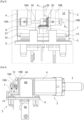
Figure 1 ] shows a perspective view of a connector assembly provided with a coupling system and a device for driving said coupling system, according to one embodiment; - [
Figure 2 ] shows the coupling system and its drive device of the assembly offigure 1 , with a nut of the drive device having been removed in order to show a threaded rod; - [
Figure 3 ] shows a front view of the coupling system and its drive device of the assembly offigure 1 , in a final coupling position, according to one embodiment; - [
Figure 4 ] shows a side view of the connector assembly, the coupling system and its drive device offigure 1 , in a final coupling position, according to one embodiment; - [
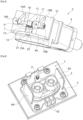
Figure 5 ] shows one of the connectors of the assembly offigure 1 , provided with a coupling nut and the drive device, according to one embodiment; - [
Figure 6 ] shows the other one of the connectors of the assembly offigure 1 , provided with a threaded coupling rod, said connector being mounted on a support, according to one embodiment; - [
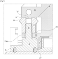
Figure 7 ] shows a cross-sectional side view of the connector coupling system offigure 1 , in the final coupling position, according to one embodiment; - [
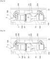
Figure 8 ] shows a cross-sectional side view of the two connectors offigure 1 , before coupling, according to one embodiment; - [
Figure 9 ] shows a cross-sectional side view of the two connectors offigure 1 , in an initial coupling position, according to one embodiment; - [
Figure 10 ] shows a cross-sectional side view of the two connectors offigure 1 , in the final coupling position, according to one embodiment; - [
Figure 11 ] shows a top view of a CPA (Connector Position Assurance) device in the open or unlocked position mounted on the connector assembly offigure 1 , according to one embodiment; - [
Figure 12 ] shows a top view of the CPA device offigure 11 in a first closed or locked position, according to one embodiment; - [
Figure 13 ] shows a top view of the CPA device offigure 11 in a second closed or locked position, according to one embodiment; - [
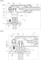
Figure 14 ] shows a side view of the CPA device offigure 11 in an open or unlocked position, according to one embodiment; - [
Figure 15 ] shows a side view of the CPA device offigure 11 in the closed or locked position, according to one embodiment; - [
Figure 16 ] shows a flowchart of a method for coupling the connector assembly offigure 1 , according to one embodiment; - [
Figure 17 ] shows a flowchart of a method for uncoupling the connector assembly offigure 1 , according to one embodiment. - In the various figures, the same reference signs designate identical, similar or corresponding elements.
- The present description relates to an
electrical connector assembly 1 comprising aconnector 2 and amating connector 3. - The term "mating connector" refers to an element adapted to be electrically connected to a connector. This can be another connector or any other element, for example, a casing, a base, a wall, etc., on which connector elements, such as electrical contacts, are mounted.
- One from among the
connector 2 and themating connector 3 comprises one or more female electrical contacts and the other one from among theconnector 2 and themating connector 3 comprises one or more corresponding male electrical contacts. - In the present description, terms such as "upper", "lower", "top", "bottom", "front", "rear", etc., are purely conventional and refer, where appropriate, to the orientations as shown in the figures.
-
Figure 1 shows a particular embodiment of theassembly 1 comprising theconnector 2 and themating connector 3. This embodiment is purely illustrative and non-limiting. - The
connector 2 can comprise acasing 4 housingelectrical contacts 50, shown as a cross-section infigures 8-10 , which are electrically connected toelectrical cables 51. - The
mating connector 3 can comprise abase 5, a femalemechanical coupling part 6, adapted to receive a malemechanical coupling part 4A of theconnector 2, andelectrical contacts 52, shown infigures 8-10 . Thefemale part 6 is a receiving recess provided, for example, insidewalls base 5. Themale part 4A can comprise part of thecasing 4. Thebase 5 can extend in a plane orthogonal to a coupling direction of theconnector 2 and of themating connector 3. - In the embodiment described herein, the
electrical contacts 50 of theconnector 2 are female contacts and theelectrical contacts 52 of themating connector 3 are male contacts. However, theconnector 2 could have male contacts and themating connector 3 female contacts. - The
connector assembly 1 also comprises a coupling system for coupling or assembling theconnector 2 and themating connector 3. Coupling theconnector 2 and themating connector 3 allows theconnector 2 and themating connector 3 to be assembled by moving them towards each other into a final coupling position, shown infigure 10 , in which theconnector 2 and themating connector 3 are electrically connected. - In the present description, the coupling system comprises two coupling elements including a
nut 7 and a threadedrod 8. Thenut 7 is mounted on one from among theconnector 2 and themating connector 3, and the threadedrod 8 is mounted on the other one from among theconnector 2 and themating connector 3.Figure 2 shows the coupling system offigure 1 without thecoupling nut 7 in order to reveal the threadedcoupling rod 8.Figure 3 shows the coupling system offigure 1 , as a front view, in the final coupled position. - In a particular embodiment, the
nut 7 is mounted on theconnector 2 and the threadedrod 8 is mounted on themating connector 3. Thenut 7 comprises a tapped hole for screwing onto the threadedrod 8. - In this embodiment, the
nut 7 is mounted on theconnector 2 for free rotation about a screwing axis A1 parallel to the coupling or assembly direction, and the threadedrod 8 is fixedly mounted on themating connector 3. - The threaded
rod 8 can be integral with thebase 5. The axis of the threadedrod 8 and the screwing axis A1 are coincident. These axes can be orthogonal to the plane of thebase 5. - The
nut 7 can be mounted between anupper bearing surface 9 and alower bearing surface 10 of theconnector 2, perpendicular to the screwing axis A1. - The
upper bearing surface 9 can be supported by astop component 11. Thestop component 11 can be integral with thecasing 4 and can project from afront wall 12 of thecasing 4. It can assume, for example, the shape of a rectangular parallelepiped. The bearingsurface 9 can be the lower surface of thestop component 11. - The
lower bearing surface 10 can be supported by aflange 13 of theconnector 2, integral with thefront wall 12 of thecasing 4. Theflange 13 advantageously provides a throughhole 13A for the passage of the threadedcoupling rod 8. - The distance separating the two bearing
surfaces nut 7 along the screwing axis A1, so as to give thenut 7 clearance in the screwing/unscrewing direction. - The
coupling nut 7 can be held between the two bearingsurfaces centring stud 14 downwardly projecting from theupper bearing surface 9 into the tapped hole in thenut 7, more specifically into the upper opening of the tapped hole, as shown infigure 7 , which shows a cross-sectional view of thenut 7 and of the threadedrod 8 in the final coupling position of theconnector 2 and themating connector 3. - The
centring stud 14 can be angled in order to facilitate its insertion into the tapped hole in thenut 7 by slight resilient deformation of thestop component 11, when thenut 7 is mounted on theconnector 2. - Optionally, the upper opening of the tapped hole in the
nut 7 that is intended to receive thecentring stud 14 can have a chamfer in order to further facilitate the insertion of thecentring stud 14. - Another centring stud also could be provided on the
lower bearing surface 10. In this case, this other centring stud provides a through hole for the passage of the threadedrod 8. - When the
nut 7 is screwed onto the threadedrod 8, it is arranged in order to translationally move on the threadedrod 8 parallel to the screwing axis A1. During this translational movement, by bearing against thesurface 10 of theflange 13 of theconnector 2, thenut 7 is arranged to cause theconnector assembly 2 to translationally move parallel to the screwing axis A1, so as to bring theconnector 2 closer to themating connector 3, until it reaches a final coupling or assembly position, in which the electrical connection of theconnector 2 and themating connector 3 is assured. The final coupling position can be an abutment position, in which theconnector 2 is in abutment against themating connector 3. For example, as shown infigure 7 , alower edge 27 of thecasing 4 of theconnector 2 is in abutment against thebase 5 of themating connector 3. - The
connector assembly 1 further comprises a device for driving thecoupling system drive shaft 16 and agear system 17. Its purpose is to rotate thenut 7 using thedrive shaft 16, by means of thegear system 17. Thegear system 17 is arranged to transmit a rotational movement of theshaft 16, rotated about an axis of rotation A2, to thenut 7, rotated about the screwing axis A1, with the axis of rotation A2 and the screwing axis A1 being non-parallel. The axes A1 and A2 are shown infigures 2 and3 . - The axis of rotation A2 and the screwing axis A1 can be concurrent or non-concurrent. In any case, the axis of rotation A2, or a projection of the axis of rotation A2 in a plane containing the screwing axis A1, is separated from the screwing axis A1 by an angle that is strictly greater than 0° and is strictly less than 180°. For example, this angle is 90°.
- In a particular embodiment, the screwing axis A1 and the axis of rotation A2 are concurrent and the axis of rotation A2 is oriented at 90° to the screwing axis A1.
- The
drive device connector 2 and themating connector 3 that supports the rotary coupling element of the coupling system, in this case thenut 7. In the embodiment described herein, the drive device is provided on theconnector 2 supporting thenut 7. - The
drive shaft 16 is rotatably mounted on theconnector 2, for example, by means ofbearings casing 4. Thebearings front wall 12 of thecasing 4, and disposed on either side of thestop component 11. In this case, thestop component 11 can provide a through hole for the passage of thedrive shaft 16. - The two ends of the
drive shaft 16 can be provided with means for coupling to a rotary drive tool or a screwing and/or unscrewing tool. In one embodiment, each of the two ends of thedrive shaft 16 is provided with ascrew head shaft 16 to be driven using a screwing tool. - The
connector 2 can be adapted to provide two external accesses, respectively at the two ends of thedrive shaft 16, from two opposite sides of thecasing 4. In other words, theconnector 2 can be free of obstructions between each of the ends of thedrive shaft 16 and the outside of theconnector 2. Two access passages thus can be provided in order to leave free access to both ends of thedrive shaft 16. - In one embodiment, the
gear system 17 comprises a bevel gear. This bevel gear is used to transmit the movement between thedrive shaft 16 and thecoupling nut 7. - The
bevel gear system 17 can comprise two intermeshedgearwheels drive shaft 16 and by thenut 7, respectively. Thegearwheel 20 supported by thedrive shaft 16 is a driving wheel, and thegearwheel 21 supported by thenut 7 is a driven wheel. - The toothing of each of the
gearwheels - The two
gearwheels - Alternatively, the driving
gearwheel 20 can have a larger diameter than the drivengearwheel 21, for example, twice as large, so as to reduce the force or effort required to rotate theshaft 16 and thus turn thenut 7. - The
gearwheel 20 can be fixed on theshaft 16 and be rotationally integral with theshaft 16. Alternatively, theshaft 16 and thegearwheel 20 can be produced as a single, one-piece part, with thegearwheel 20 being produced by a conical surface supporting toothing, for example, by moulding or overmoulding. - The
gearwheel 21 can be produced as a single, one-piece part with thenut 7. As an alternative embodiment, thegearwheel 21 could be fixed to thenut 7 and be rotationally integral with thenut 7. - Optionally, the
connector assembly 1 can comprise a coupling orassembly assurance device 22, also called Connector Position Assurance device, or CPA device. An embodiment of aCPA device 22 mounted on theconnector assembly 1 offigure 1 , is shown infigures 11 to 15 . It should be noted that this embodiment of theCPA device 22 is purely illustrative and non-limiting. - The
CPA device 22 can comprise alocking component 23 mounted on one from among theconnector 2 and themating connector 3 and at least one recess 24 for receiving thelocking component 23 provided on the other one from among theconnector 2 and themating connector 3, arranged to lock theconnector 2 and themating connector 3 in the final coupling position. - In a particular embodiment, the locking
component 23 is rotatably mounted on thenut 7 and can comprise a body part, mounted around thenut 7, and one or two lockingfingers figures 14 and 15 , thenut 7 can be, for example, cylindrical and support thegearwheel 21 on an upper end portion. Thelocking component 23 can be pivotably mounted on a lower portion of thenut 7. - The
front wall 12 of thecasing 4 optionally can have a concave part in order to provide a gap between thefront wall 12 of thecasing 4 and thenut 7 in order to receive the body part of thelocking component 23, mounted on thenut 7, as shown infigures 11 to 13 . - In one embodiment, the locking
component 23 comprises two lockingfingers fingers fingers - The
mating connector 3, notably shown infigure 6 , can comprise two recesses, such as thenotches figures 6 ,14 and 15 , for respectively receiving the two lockingfingers connector 2 and themating connector 3 are in the final coupling position and thus blocking theconnector 2 and themating connector 3 in this final coupling position by preventing them from moving away from each other in the opposite direction to the coupling direction. The two lockingfingers notches notches base 5, as shown infigure 6 . When theconnector 2 and themating connector 3 are in the final coupling position, either of the two lockingfingers corresponding notch mating connector 3. - It should be noted that the two locking
fingers connector 2, respectively located on either side of the plane orthogonal to the axis of rotation A2 and containing the screwing axis A1. - The
stop component 11 can comprise a bearingsurface 26 for the drivinggearwheel 20, perpendicular to the axis of rotation A2 of theshaft 16, as shown infigures 2 and5 . - A method for coupling the
connector 2 and themating connector 3 will now be described, with reference tofigures 8, 9 ,10 and16 , according to a particular embodiment. It should be noted that infigures 8, 9 and10 , for the sake of clarity and in order to better understand the coupling process, thedrive shaft 16 is not shown. - In a first step E1, the
connector 2 is brought closer to themating connector 3 in an initial pre-coupling position, as shown infigure 8 . In this pre-coupling position, themale coupling part 4A of thecasing 4 of theconnector 2 is placed opposite thefemale coupling part 6 of themating connector 3. - In a second step E2, the
male part 4A of theconnector 4 is introduced into thefemale part 6 of themating connector 3 until the free end of the threadedrod 8 slightly penetrates the tapped hole in thenut 7, through the throughhole 13A of theflange 13 of theconnector 2, by a translational movement in the coupling direction, as shown infigure 9 . In this intermediate coupling position, the free end of the threadedrod 8 is in abutment against the internal thread of thenut 7, and the electrical connection between theconnector 2 and themating connector 3 has not yet been established. Indeed, as shown infigure 9 , themale contacts 52 of themating connector 3 have not yet been introduced into thefemale contacts 50 of theconnector 2. This second coupling initiation step can be carried out manually by a user. - During a third step E3, the
drive shaft 16 is rotated, for example, using a rotary drive or screwing tool, or optionally manually. To this end, the rotary drive or screwing tool is coupled to one of the two screw heads 19A, 19B and then actuated in order to rotate theshaft 16. - Either
screw head drive shaft 16. The selectedscrew head connector 2. Therefore, this selection can depend on the environment around theconnector 2. For example, one or more obstacles are likely to block access to one of the ends of theshaft 16, on one side of theconnector 2, but leave free access to the other end of theshaft 16, on the opposite side of theconnector 2. The fact that thedrive shaft 16 can be rotated by either of its two ends provides significant access flexibility for coupling theconnector 2 and themating connector 3. For example, when manufacturing a vehicle comprising theconnector 2 and themating connector 3, it can be more convenient and/or easier to use one of the two ends of theshaft 16 for the rotation thereof, whereas after the vehicle enters into service, during repairs or maintenance, it can be more convenient to use the other end of theshaft 16 for the rotation thereof. - During step E3, the rotational movement of the
shaft 16 is transmitted to thenut 7 by means of the bevel gear, in this case comprising thebevel gearwheels gear system shaft 16, rotated about the axis of rotation A2, to be transmitted to thenut 7, rotated about the screwing axis A1, with the axis of rotation A2 and the screwing axis A1 of thenut 7 being different and non-parallel. In the example described herein, the axes A1 and A2 are concurrent and separated by an angle of 90°. This results in a 90° change in angle or direction between rotating theshaft 16 and rotating thenut 7. - By rotating the
shaft 16, thenut 7 is screwed onto the threadedrod 8 and, by bearing on theflange 13 of theconnector 2, it pushes the whole of theconnector 2 towards themating connector 3. Thus, under the action of theshaft 16 rotated about the axis A2, theconnector 2 approaches themating connector 3 in a translational movement parallel to the screwing axis A1. - The
shaft 16 is rotated to a final coupling position, as shown infigure 10 . Advantageously, this can correspond to a stop position of theconnector 2 against themating connector 3, as shown infigure 7 . In the final coupling position, themale contacts 52 of themating connector 3 are electrically connected to thefemale contacts 50 of theconnector 2. - In the event that the
connector assembly 1 is equipped with theCPA device 22, the coupling method can optionally comprise a fourth locking step E4. During this step E4, theconnector 2 and themating connector 3 can be locked in the final coupling position by rotating or pivoting thelocking component 23 so as to move it from a rest position to a locking position. Preferably, when thelocking component 23, which is mounted on thenut 7, is pivoted about the screwing axis A1, thenut 7 is not rotated. In order to pivot thelocking component 23, an operator manually pivots, for example, one of the lockingfingers corresponding notch locking component 23 can range between -45° and +45°, preferably between -30° and +30°, for example, it can range between -14° and +14°. Either lockingfinger connector 2 and themating connector 3 in the final coupling position. This selection can depend on environmental constraints around theconnector 2 and themating connector 3 that are likely to block access to one of the locking fingers but leave free access to the other locking finger. - Advantageously, the locking
component 23 can be held by hard points, i.e., points of mechanical resistance, in each of the three positions shown infigures 11 ,12 and 13 , namely, in the rest position and in the two different locked positions. - A method for uncoupling the
connector 2 and themating connector 3 will now be described, with reference tofigure 17 , according to a particular embodiment. - In order to uncouple and disconnect the
connector 2 and themating connector 3, if they have been locked in the final coupling position by theCPA device 22, the unlockingcomponent 23 is firstly unlocked by rotating in the opposite direction to the locking direction, so as to disengage the lockingfinger corresponding notch - After unlocking, during a step E6, the
drive shaft 16 is rotated in the opposite direction to the direction of rotation applied during coupling, advantageously using a rotary drive or screwing/unscrewing tool coupled to one of the screw heads 19A, 19B, or optionally manually. Thescrew head connector 2 and themating connector 3 during uncoupling. During uncoupling, one of the sides of theconnector assembly 1 can be easy to access so as to allow access to one of the ends of theshaft 16, with the other side being obstructed and not allowing access to the other end of theshaft 16. The counter-rotational movement of theshaft 16 is transmitted to thenut 7 by means of thegear system nut 7 is thus unscrewed from the threadedrod 8 and pushes theconnector 2 in a translational movement parallel to the screwing axis A1, in an opposite direction to the coupling direction, by pressing thenut 7 against theupper bearing surface 9 of thestop component 23, during step E6. In other words, when thenut 7 is unscrewed under the action of the rotational drive of theshaft 16 in the opposite direction to the direction of rotation applied during coupling, it pushes theconnector 2, by bearing against thestop component 11, so as to move theconnector 2 away from themating connector 3 along the screwing axis A1. - During a subsequent step E7, the
nut 7 is separated from the threadedrod 8 and theconnector 2 and themating connector 3 can be completely uncoupled. - In the above description, the nut and threaded rod coupling system comprises a nut rotatably mounted on one from among the connector and the mating connector, and a threaded rod fixedly mounted on the other one from among the connector and the mating connector. As an alternative embodiment, the nut and threaded rod coupling system can comprise a threaded rod rotatably mounted on one from among the connector and the mating connector, and a nut fixedly mounted on the other one from among the connector and the mating connector. In this case, the threaded rod can support a driven gearwheel, for example, on a screw head, meshed with the driving gearwheel supported by the drive shaft.
- In the above description, the gear system of the drive device comprises a bevel gear. Alternatively, the gear system could comprise a worm gearwheel.
- It should be understood that various modifications and/or improvements obvious to a person skilled in the art can be made to the various embodiments described in the present description.
Claims (15)
- Connector assembly comprising a connector (2) and a mating connector (3), said connector (2) and said mating connector (3) being configured to be coupled together by means of a coupling system comprising a nut (7) and a threaded rod (8), so as to electrically connect the connector (2) and the mating connector (3), with one from among the nut (7) and the threaded rod (8) being rotatably mounted on one from among the connector (2) and the mating connector (3) and the other one from among the nut (7) and the threaded rod (8) being fixedly mounted on the other one from among the connector (2) and the mating connector (3), said assembly comprising a device for driving the coupling system, comprising a drive shaft (16) and a gear system (17) configured to transmit a rotational movement of the drive shaft (16), rotated about an axis of rotation (A2), to the rotary element (7) of the coupling system, rotated about a screwing axis (A1), with the axis of rotation (A2) of the drive shaft (16) and the screwing axis (A1) of the rotary element (7) of the coupling system being non-parallel.
- Assembly according to Claim 1, wherein the gear system (17) is a bevel gear system.
- Assembly according to Claim 1 or 2, wherein said gear system (17) comprises a driving gearwheel (20) supported by the drive shaft (16) and a driven gearwheel (21) supported by the rotary element (7) of the coupling system.
- Assembly according to Claim 3, characterised in that the two gearwheels (20, 21) have the same diameter.
- Assembly according to Claim 3, characterised in that the diameter of the gearwheel supported by the drive shaft is greater than that of the gearwheel supported by the rotary element of the coupling system.
- Assembly according to any of Claims 1 to 5, wherein the axis of rotation (A2), or a projection of the axis of rotation (A2) in a plane comprising the screwing axis (A1), is oriented at 90° to the screwing axis (A1).
- Assembly according to any of Claims 1 to 6, comprising two access passages provided to leave free access to the two ends of the drive shaft (16).
- Assembly according to any of Claims 1 to 7, wherein each of the two ends of the drive shaft (16) is provided with means (19A, 19B) for coupling to a rotary drive tool.
- Assembly according to any of Claims 1 to 8, comprising a coupling assurance device (22) comprising a locking component (23) rotatably mounted on the rotary element (7) of the coupling system, mounted on one from among the connector (2) and the mating connector (3), said locking component (23) comprising at least one locking finger (25A, 25B) arranged to be introduced, by rotating about the screwing axis (A1), into a notch (24A, 24B) provided in the other one from among the connector (2) and the mating connector (3), in a final coupling position of the connector (2) and of the mating connector (3), so as to assure and lock said final coupling position.
- Assembly according to Claim 9, wherein the locking component (23) comprises two locking fingers (25a, 25B) configured to be selectively introduced into two respective notches (24A, 24B) provided in the other one from among the connector (2) and the mating connector (3) in the final coupling position of the connector (2) and of the mating connector (3).
- Assembly according to any of Claims 1 to 10, wherein said rotary element of the coupling system is the nut (7).
- Assembly according to Claim 11, wherein the nut (7) is mounted on one from among the connector (2) and the mating connector (3), between two bearing surfaces (9, 10) of said connector (2) or mating connector (3), perpendicular to the screwing axis (A1), by inserting a centring stud (14) projecting from one of the two bearing surfaces (9) into a tapped hole in the nut (7).
- Assembly according to Claim 12, wherein said centring stud (14) is angled so as to facilitate its insertion into the tapped hole in the nut (7).
- Connector intended to be used in a connector assembly (1) according to any of Claims 1 to 13, and comprising a device for driving the coupling system of the connector assembly (1), said drive device comprising a drive shaft (16) and a gear system (17) arranged in order to transmit a rotational movement of the drive shaft (16), rotated about an axis of rotation (A2), to the rotary element (7) of the coupling system, rotated about a screwing axis (A1), with the axis of rotation (A2) of the drive shaft (16) and the screwing axis (A1) of the rotary element (7) of the coupling system being non-parallel.
- Vehicle comprising the connector assembly according to any of Claims 1 to 13.
Applications Claiming Priority (1)
| Application Number | Priority Date | Filing Date | Title |
|---|---|---|---|
| FR2300323A FR3145068A1 (en) | 2023-01-12 | 2023-01-12 | Connector set |
Publications (1)
| Publication Number | Publication Date |
|---|---|
| EP4401249A1 true EP4401249A1 (en) | 2024-07-17 |
Family
ID=86007645
Family Applications (1)
| Application Number | Title | Priority Date | Filing Date |
|---|---|---|---|
| EP24151654.1A Pending EP4401249A1 (en) | 2023-01-12 | 2024-01-12 | Connector assembly |
Country Status (2)
| Country | Link |
|---|---|
| EP (1) | EP4401249A1 (en) |
| FR (1) | FR3145068A1 (en) |
Citations (5)
| Publication number | Priority date | Publication date | Assignee | Title |
|---|---|---|---|---|
| CN101394041A (en) * | 2007-09-21 | 2009-03-25 | 宏正自动科技股份有限公司 | Connector module, mechanism and method for driving two screws to advance and retreat simultaneously |
| CN216055493U (en) * | 2021-10-12 | 2022-03-15 | 深圳市德冠精密组件有限公司 | DVI connects uses latch mechanism |
| CN216251378U (en) * | 2021-12-08 | 2022-04-08 | 黄河科技集团信息产业发展有限公司 | Computer motherboard connects conversion equipment |
| CN114824927A (en) * | 2022-05-25 | 2022-07-29 | 江西兰丰科技有限公司 | Display connector lug convenient to insert |
| CN218070376U (en) * | 2022-05-24 | 2022-12-16 | 江苏智新胜新能源有限公司 | Connector based on machine vision |
-
2023
- 2023-01-12 FR FR2300323A patent/FR3145068A1/en active Pending
-
2024
- 2024-01-12 EP EP24151654.1A patent/EP4401249A1/en active Pending
Patent Citations (5)
| Publication number | Priority date | Publication date | Assignee | Title |
|---|---|---|---|---|
| CN101394041A (en) * | 2007-09-21 | 2009-03-25 | 宏正自动科技股份有限公司 | Connector module, mechanism and method for driving two screws to advance and retreat simultaneously |
| CN216055493U (en) * | 2021-10-12 | 2022-03-15 | 深圳市德冠精密组件有限公司 | DVI connects uses latch mechanism |
| CN216251378U (en) * | 2021-12-08 | 2022-04-08 | 黄河科技集团信息产业发展有限公司 | Computer motherboard connects conversion equipment |
| CN218070376U (en) * | 2022-05-24 | 2022-12-16 | 江苏智新胜新能源有限公司 | Connector based on machine vision |
| CN114824927A (en) * | 2022-05-25 | 2022-07-29 | 江西兰丰科技有限公司 | Display connector lug convenient to insert |
Also Published As
| Publication number | Publication date |
|---|---|
| FR3145068A1 (en) | 2024-07-19 |
Similar Documents
| Publication | Publication Date | Title |
|---|---|---|
| US5618204A (en) | Circular bulkhead connector assembly | |
| CN101479147B (en) | System for locking the first shaft relative to the second without backlash | |
| US7703309B2 (en) | Electric steering lock device and assembling method | |
| JP5824762B2 (en) | Plug connector | |
| CN104011944B (en) | Self-aligning connector assembly | |
| US7351117B1 (en) | Electrical connector assembly having pre-staging and final staging contact configurations | |
| JP7083355B2 (en) | Port lock actuator device for vehicle inlet | |
| US20080178643A1 (en) | Assembling method of electric steering lock device | |
| JP5072421B2 (en) | Electrical connector | |
| JP5578927B2 (en) | Low insertion force connector | |
| CN113895287B (en) | Unlocking device and battery replacement device including the same | |
| CN113410710A (en) | Cable connector and cable device | |
| EP3386040B1 (en) | Plug connector and method of producing a plug connection | |
| CN111886175B (en) | Coupling system | |
| CN101895048B (en) | Installing and removing tool for connecting F male coaxial cable connector | |
| CN102217144A (en) | Electric partition feedthrough | |
| EP0399756B1 (en) | Headlight adjustment | |
| US7281939B1 (en) | Bolt driven connector | |
| US5308254A (en) | Connectors connecting device | |
| WO2012118145A1 (en) | Connector fitting jig and low-insertion-force connector | |
| CN1788394A (en) | Lever type electrical connector assembly with improved locking means | |
| US6379158B1 (en) | Steering unit-mounting structure | |
| CN223559648U (en) | Multistage chain driver controller | |
| US12618469B1 (en) | Park lock actuator with manual release and shipping position | |
| CN222530967U (en) | Plug and connector |
Legal Events
| Date | Code | Title | Description |
|---|---|---|---|
| PUAI | Public reference made under article 153(3) epc to a published international application that has entered the european phase |
Free format text: ORIGINAL CODE: 0009012 |
|
| STAA | Information on the status of an ep patent application or granted ep patent |
Free format text: STATUS: THE APPLICATION HAS BEEN PUBLISHED |
|
| AK | Designated contracting states |
Kind code of ref document: A1 Designated state(s): AL AT BE BG CH CY CZ DE DK EE ES FI FR GB GR HR HU IE IS IT LI LT LU LV MC ME MK MT NL NO PL PT RO RS SE SI SK SM TR |
|
| RAP3 | Party data changed (applicant data changed or rights of an application transferred) |
Owner name: APTIV TECHNOLOGIES AG |
|
| STAA | Information on the status of an ep patent application or granted ep patent |
Free format text: STATUS: REQUEST FOR EXAMINATION WAS MADE |
|
| 17P | Request for examination filed |
Effective date: 20250116 |