EP4401248A1 - Terminal, connector and connector assembly - Google Patents
Terminal, connector and connector assembly Download PDFInfo
- Publication number
- EP4401248A1 EP4401248A1 EP24151574.1A EP24151574A EP4401248A1 EP 4401248 A1 EP4401248 A1 EP 4401248A1 EP 24151574 A EP24151574 A EP 24151574A EP 4401248 A1 EP4401248 A1 EP 4401248A1
- Authority
- EP
- European Patent Office
- Prior art keywords
- terminal
- terminal board
- locking member
- elastic
- elastic contact
- Prior art date
- Legal status (The legal status is an assumption and is not a legal conclusion. Google has not performed a legal analysis and makes no representation as to the accuracy of the status listed.)
- Pending
Links
Images



Classifications
-
- H—ELECTRICITY
- H01—ELECTRIC ELEMENTS
- H01R—ELECTRICALLY-CONDUCTIVE CONNECTIONS; STRUCTURAL ASSOCIATIONS OF A PLURALITY OF MUTUALLY-INSULATED ELECTRICAL CONNECTING ELEMENTS; COUPLING DEVICES; CURRENT COLLECTORS
- H01R12/00—Structural associations of a plurality of mutually-insulated electrical connecting elements, specially adapted for printed circuits, e.g. printed circuit boards [PCB], flat or ribbon cables, or like generally planar structures, e.g. terminal strips, terminal blocks; Coupling devices specially adapted for printed circuits, flat or ribbon cables, or like generally planar structures; Terminals specially adapted for contact with, or insertion into, printed circuits, flat or ribbon cables, or like generally planar structures
- H01R12/70—Coupling devices
- H01R12/71—Coupling devices for rigid printing circuits or like structures
- H01R12/712—Coupling devices for rigid printing circuits or like structures co-operating with the surface of the printed circuit or with a coupling device exclusively provided on the surface of the printed circuit
- H01R12/716—Coupling device provided on the PCB
- H01R12/718—Contact members provided on the PCB without an insulating housing
-
- H—ELECTRICITY
- H01—ELECTRIC ELEMENTS
- H01R—ELECTRICALLY-CONDUCTIVE CONNECTIONS; STRUCTURAL ASSOCIATIONS OF A PLURALITY OF MUTUALLY-INSULATED ELECTRICAL CONNECTING ELEMENTS; COUPLING DEVICES; CURRENT COLLECTORS
- H01R13/00—Details of coupling devices of the kinds covered by groups H01R12/70 or H01R24/00 - H01R33/00
- H01R13/40—Securing contact members in or to a base or case; Insulating of contact members
-
- H—ELECTRICITY
- H01—ELECTRIC ELEMENTS
- H01R—ELECTRICALLY-CONDUCTIVE CONNECTIONS; STRUCTURAL ASSOCIATIONS OF A PLURALITY OF MUTUALLY-INSULATED ELECTRICAL CONNECTING ELEMENTS; COUPLING DEVICES; CURRENT COLLECTORS
- H01R12/00—Structural associations of a plurality of mutually-insulated electrical connecting elements, specially adapted for printed circuits, e.g. printed circuit boards [PCB], flat or ribbon cables, or like generally planar structures, e.g. terminal strips, terminal blocks; Coupling devices specially adapted for printed circuits, flat or ribbon cables, or like generally planar structures; Terminals specially adapted for contact with, or insertion into, printed circuits, flat or ribbon cables, or like generally planar structures
- H01R12/50—Fixed connections
- H01R12/51—Fixed connections for rigid printed circuits or like structures
- H01R12/55—Fixed connections for rigid printed circuits or like structures characterised by the terminals
- H01R12/57—Fixed connections for rigid printed circuits or like structures characterised by the terminals surface mounting terminals
-
- H—ELECTRICITY
- H01—ELECTRIC ELEMENTS
- H01R—ELECTRICALLY-CONDUCTIVE CONNECTIONS; STRUCTURAL ASSOCIATIONS OF A PLURALITY OF MUTUALLY-INSULATED ELECTRICAL CONNECTING ELEMENTS; COUPLING DEVICES; CURRENT COLLECTORS
- H01R12/00—Structural associations of a plurality of mutually-insulated electrical connecting elements, specially adapted for printed circuits, e.g. printed circuit boards [PCB], flat or ribbon cables, or like generally planar structures, e.g. terminal strips, terminal blocks; Coupling devices specially adapted for printed circuits, flat or ribbon cables, or like generally planar structures; Terminals specially adapted for contact with, or insertion into, printed circuits, flat or ribbon cables, or like generally planar structures
- H01R12/70—Coupling devices
- H01R12/7088—Arrangements for power supply
-
- H—ELECTRICITY
- H01—ELECTRIC ELEMENTS
- H01R—ELECTRICALLY-CONDUCTIVE CONNECTIONS; STRUCTURAL ASSOCIATIONS OF A PLURALITY OF MUTUALLY-INSULATED ELECTRICAL CONNECTING ELEMENTS; COUPLING DEVICES; CURRENT COLLECTORS
- H01R13/00—Details of coupling devices of the kinds covered by groups H01R12/70 or H01R24/00 - H01R33/00
- H01R13/46—Bases; Cases
- H01R13/502—Bases; Cases composed of different pieces
-
- H—ELECTRICITY
- H01—ELECTRIC ELEMENTS
- H01R—ELECTRICALLY-CONDUCTIVE CONNECTIONS; STRUCTURAL ASSOCIATIONS OF A PLURALITY OF MUTUALLY-INSULATED ELECTRICAL CONNECTING ELEMENTS; COUPLING DEVICES; CURRENT COLLECTORS
- H01R13/00—Details of coupling devices of the kinds covered by groups H01R12/70 or H01R24/00 - H01R33/00
- H01R13/66—Structural association with built-in electrical component
- H01R13/665—Structural association with built-in electrical component with built-in electronic circuit
- H01R13/6658—Structural association with built-in electrical component with built-in electronic circuit on printed circuit board
-
- H—ELECTRICITY
- H01—ELECTRIC ELEMENTS
- H01R—ELECTRICALLY-CONDUCTIVE CONNECTIONS; STRUCTURAL ASSOCIATIONS OF A PLURALITY OF MUTUALLY-INSULATED ELECTRICAL CONNECTING ELEMENTS; COUPLING DEVICES; CURRENT COLLECTORS
- H01R12/00—Structural associations of a plurality of mutually-insulated electrical connecting elements, specially adapted for printed circuits, e.g. printed circuit boards [PCB], flat or ribbon cables, or like generally planar structures, e.g. terminal strips, terminal blocks; Coupling devices specially adapted for printed circuits, flat or ribbon cables, or like generally planar structures; Terminals specially adapted for contact with, or insertion into, printed circuits, flat or ribbon cables, or like generally planar structures
- H01R12/70—Coupling devices
- H01R12/7005—Guiding, mounting, polarizing or locking means; Extractors
- H01R12/7011—Locking or fixing a connector to a PCB
-
- H—ELECTRICITY
- H01—ELECTRIC ELEMENTS
- H01R—ELECTRICALLY-CONDUCTIVE CONNECTIONS; STRUCTURAL ASSOCIATIONS OF A PLURALITY OF MUTUALLY-INSULATED ELECTRICAL CONNECTING ELEMENTS; COUPLING DEVICES; CURRENT COLLECTORS
- H01R13/00—Details of coupling devices of the kinds covered by groups H01R12/70 or H01R24/00 - H01R33/00
- H01R13/02—Contact members
- H01R13/10—Sockets for co-operation with pins or blades
- H01R13/11—Resilient sockets
- H01R13/113—Resilient sockets co-operating with pins or blades having a rectangular transverse section
-
- H—ELECTRICITY
- H01—ELECTRIC ELEMENTS
- H01R—ELECTRICALLY-CONDUCTIVE CONNECTIONS; STRUCTURAL ASSOCIATIONS OF A PLURALITY OF MUTUALLY-INSULATED ELECTRICAL CONNECTING ELEMENTS; COUPLING DEVICES; CURRENT COLLECTORS
- H01R13/00—Details of coupling devices of the kinds covered by groups H01R12/70 or H01R24/00 - H01R33/00
- H01R13/02—Contact members
- H01R13/15—Pins, blades or sockets having separate spring member for producing or increasing contact pressure
- H01R13/187—Pins, blades or sockets having separate spring member for producing or increasing contact pressure with spring member in the socket
-
- H—ELECTRICITY
- H01—ELECTRIC ELEMENTS
- H01R—ELECTRICALLY-CONDUCTIVE CONNECTIONS; STRUCTURAL ASSOCIATIONS OF A PLURALITY OF MUTUALLY-INSULATED ELECTRICAL CONNECTING ELEMENTS; COUPLING DEVICES; CURRENT COLLECTORS
- H01R13/00—Details of coupling devices of the kinds covered by groups H01R12/70 or H01R24/00 - H01R33/00
- H01R13/02—Contact members
- H01R13/193—Means for increasing contact pressure at the end of engagement of coupling part, e.g. zero insertion force or no friction
-
- H—ELECTRICITY
- H01—ELECTRIC ELEMENTS
- H01R—ELECTRICALLY-CONDUCTIVE CONNECTIONS; STRUCTURAL ASSOCIATIONS OF A PLURALITY OF MUTUALLY-INSULATED ELECTRICAL CONNECTING ELEMENTS; COUPLING DEVICES; CURRENT COLLECTORS
- H01R13/00—Details of coupling devices of the kinds covered by groups H01R12/70 or H01R24/00 - H01R33/00
- H01R13/40—Securing contact members in or to a base or case; Insulating of contact members
- H01R13/42—Securing in a demountable manner
- H01R13/428—Securing in a demountable manner by resilient locking means on the contact members; by locking means on resilient contact members
- H01R13/432—Securing in a demountable manner by resilient locking means on the contact members; by locking means on resilient contact members by stamped-out resilient tongue snapping behind shoulder in base or case
-
- H—ELECTRICITY
- H01—ELECTRIC ELEMENTS
- H01R—ELECTRICALLY-CONDUCTIVE CONNECTIONS; STRUCTURAL ASSOCIATIONS OF A PLURALITY OF MUTUALLY-INSULATED ELECTRICAL CONNECTING ELEMENTS; COUPLING DEVICES; CURRENT COLLECTORS
- H01R4/00—Electrically-conductive connections between two or more conductive members in direct contact, i.e. touching one another; Means for effecting or maintaining such contact; Electrically-conductive connections having two or more spaced connecting locations for conductors and using contact members penetrating insulation
- H01R4/02—Soldered or welded connections
- H01R4/023—Soldered or welded connections between cables or wires and terminals
Definitions
- the present invention relates to a terminal, in particular to a terminal for a high-voltage connector.
- the present invention also relates to a connector comprising the terminal and a connector assembly comprising the connector.
- the terminal of high-voltage connector typically includes a terminal body, a pair of elastic contacts, and a locking member.
- the terminal body includes two terminal boards. There is a gap between two terminal boards that allows for the insertion of a mating terminal.
- a pair of elastic contact pieces are set in the gap between two terminal boards and fixed to the inner surfaces of the two terminal boards respectively, used to clamp the mating terminal inserted between them to achieve electrical connection between the terminal and the mating terminal.
- the locking member is installed on the two terminal boards of the terminal body, used to lock the terminal in the housing of the connector.
- the terminal body includes two terminal boards
- the structure of the terminal is complex, the production cost is high, and the manufacturing difficulty is high.
- the gap between the two terminal boards will change, which can lead to poor electrical contact between the terminal and the mating terminal. Therefore, the terminal of existing high-voltage connector is not suitable for vibration environments.
- the present invention has been made to overcome or alleviate at least one aspect of the above mentioned disadvantages.
- a terminal comprising of a single terminal board having a top surface and a bottom surface opposite to each other in its thickness direction; a locking member fixed to the terminal board and comprising a top plate located above the top surface of the terminal board; and an elastic contact member which is installed on the top surface of the terminal board and faces the top plate of the locking member.
- the elastic contact member is used for electrical contact with a mating terminal inserted between the elastic contact member and the locking member to achieve electrical connection between the terminal and the mating terminal.
- the locking member further comprises of a bottom plate which is fixed to the terminal board and has opposite front and rear edges in a longitudinal direction of the terminal board; a front side plate connected between the front edges of the top plate and the bottom plate; and a rear side plate connected to the rear edge of the top plate and fixed to the top surface of the terminal board.
- the top plate, bottom plate, front side plate, and rear side plate of the locking member define an inner cavity, the front end part of the terminal board is located in the inner cavity; the bottom surface of the terminal board is against an inner surface of the bottom plate of the locking member.
- the bottom plate of the locking member has opposite left and right edges in a transverse direction of the terminal board; the locking member further comprises two elastic clips respectively connected to the left and right edges of the bottom plate, the cross-section of the elastic clip is C-shaped and clamped on the side edge of the terminal board to fix the bottom plate to the terminal board.
- a positioning groove and a fixed tongue located in the positioning groove are respectively formed on each of the left and right edges of the terminal board; the elastic clip of the locking member is positioned in the positioning groove and clamps the fixed tongue.
- the locking member further comprises a fixing plate connected to a lower edge of the rear side plate, the fixing plate is perpendicularly bent outward relative to the rear side plate and fixed to the top surface of the terminal board to fix the rear side plate to the top surface of the terminal board.
- multiple riveting holes are formed on the fixing plate of the locking member, and multiple riveting posts are formed on the terminal board, the riveting posts are respectively riveted into the riveting holes to rivet the fixing plate to the terminal board.
- a positioning protrusion is formed on the front end face of the terminal board, and a positioning slot hole is formed on the front side plate of the locking member, the positioning protrusion is assembled into the positioning slot hole to position the front side plate of the locking member.
- the locking member further comprises a guide rib formed on the top plate and/or the bottom plate, the guide rib protrudes outward from the outer surface of the top plate and/or the bottom plate and extends along the longitudinal direction of the terminal board; the guide rib is suitable for fitting with a guide slot formed in the housing of the connector to guide the terminal to be inserted into the housing of the connector along the longitudinal direction of the terminal board.
- the locking member further comprises an elastic locking piece formed on the top plate and/or the bottom plate, which is adapted to engage with the housing of the connector to lock the terminal to the housing of the connector.
- the locking member further comprises a elastic pressing sheet formed on the top plate, the elastic pressing sheet is arc-shaped and protrudes towards the elastic contact member; the elastic pressing sheet is used to apply a predetermined pressure on the mating terminal inserted between the elastic contact member and the elastic pressing sheet to ensure reliable electrical contact between the mating terminal and the elastic contact member.
- the locking member further comprises an elastic locking piece formed on the bottom plate, which is adapted to engage with the housing of the connector to lock the terminal to the housing of the connector.
- the elastic contact member comprises multiple elastic arms extending along a transverse direction of the terminal board, and the multiple elastic arms are arranged in a row along the longitudinal direction of the terminal board; multiple elastic arms of the elastic contact member are used for simultaneous electrical contact with the mating terminal inserted along the transverse direction of the terminal board between the elastic contact member and the top plate of the locking member.
- the elastic contact member further comprises a first side edge portion and a second side edge portion extending along the longitudinal direction of the terminal board, and multiple elastic arms connected between the first side edge portion and the second side edge portion.
- the first side edge portion of the elastic contact member is fixed to the top surface of the terminal board, and the second side edge portion of the elastic contact member is slidably supported on the top surface of the terminal board.
- each of the terminal board, the locking member and the elastic contact member is an integral stamped part.
- the locking member is fixed to the front end part of the terminal board, and the rear end part of the terminal board extends backwards along the longitudinal direction of the terminal board beyond the locking member; the top surface of the rear end part of the terminal board is used for welding to a cable for electrical connection with the cable.
- a connector comprising of a housing; and the above terminal which is inserted into the housing.
- the terminal body of the terminal only includes a single terminal board, thus simplifying the structure of the terminal, reducing production costs and manufacturing difficulties.
- the terminals of the present invention can also make reliable electrical contact with the mating terminals in vibration environments.
- a terminal comprising of: a single terminal board having a top surface and a bottom surface opposite to each other in its thickness direction; a locking member fixed to the terminal board and comprising a top plate located above the top surface of the terminal board; and an elastic contact member which is installed on the top surface of the terminal board and faces the top plate of the locking member.
- the elastic contact member is used for electrical contact with a mating terminal inserted between the elastic contact member and the locking member to achieve electrical connection between the terminal and the mating terminal.
- a connector comprising of: a housing; and the above terminal which is inserted into the housing.
- a connector assembly comprising of: the above connector; and a mating connector suitable for mating with the connector.
- the mating connector comprises of: a mating housing for mating with the housing of the connector; and a mating terminal which is inserted between the elastic contact member of the connector and the top plate of the locking member to make electrical contact with the elastic contact member of the connector.
- Figures 1 to 4 show a terminal of a connector according to the first embodiment of the present invention.
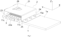
- Figure 1 shows an illustrative perspective view of a terminal of a connector according to an exemplary embodiment of the present invention when viewed from the top
- Figure 2 shows an illustrative exploded view of a terminal of a connector according to an exemplary embodiment of the present invention when viewed from the top
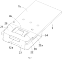
- Figure 3 shows an illustrative perspective view of a terminal of a connector according to an exemplary embodiment of the present invention when viewed from the bottom
- Figure 4 shows an illustrative exploded view of a terminal of a connector according to an exemplary embodiment of the present invention when viewed from the bottom.
- a terminal for a high-voltage connector includes: a single terminal board 1, a locking member 2, and an elastic contact member 3.
- the single terminal board 1 has opposite top surface 1a and bottom surface 1b in its thickness direction Z.
- the locking member 2 is fixed to terminal board 1 and includes a top plate 21 located above the top surface 1a of terminal board 1.
- the elastic contact member 3 is installed on the top surface 1a of terminal board 1 and faces the top plate 21 of locking member 2.
- the elastic contact member 3 is used to make electrical contact with a mating terminal (not shown) of a mating connector (not shown) inserted between the elastic contact member 3 and the top plate 21 of the locking member 2, in order to achieve electrical connection between the terminal and the mating terminal.
- the terminal body of the terminal only includes a single terminal board 1, thus simplifying the structure of the terminal and reducing the production cost and manufacturing difficulty of the terminal.
- the terminal of the present invention can also make reliable electrical contact with the mating terminal in vibration environments, without being affected by vibration.
- the locking member 2 further comprises a bottom plate 22, a front side plate 23, and a rear side plate 24.
- the bottom plate 22 is fixed to the terminal board 1 and has opposite front and rear edges in the longitudinal direction Y of the terminal board 1.
- the front side plate 23 is connected between the front edges of the top plate 21 and the bottom plate 22.
- the rear side plate 24 is connected to the rear edge of the top plate 21 and fixed to the top surface 10a of terminal board 1.
- the top plate 21, bottom plate 22, front side plate 23, and rear side plate 24 of the locking member 2 define an inner cavity 201.
- the front end part of terminal board 1 is located in the inner cavity 201, and the bottom surface 1b of terminal board 1 is against the inner surface of the bottom plate 22 of locking member 2.
- the bottom plate 22 of the locking member 2 has opposite left and right edges in the transverse direction X of the terminal board 1.
- the locking member 2 also includes two elastic clips 22a connected to the left and right edges of the bottom plate 22, respectively.
- the cross-section of the elastic clip 22a is C-shaped and clamped on the side edge of the terminal board 1 to fix the bottom plate 22 to the terminal board 1.
- a positioning groove 11a and a fixed tongue 11b located in the positioning groove 11a are formed on each of the left and right edges of the terminal board 1.
- the elastic clip 22a on the locking member 2 is positioned in the positioning groove 11a and clamps the fixed tongue 11b.
- the locking member 2 further comprises a fixing plate 25 connected to the lower edge of the rear side plate 24.
- the fixing plate 25 is perpendicularly bent outward relative to the rear side plate 24 and fixed to the top surface 1a of the terminal board 1 to fix the rear side plate 24 to the top surface 1a of the terminal board 1.
- multiple riveting holes 25a are formed on the fixing plate 25 of the locking member 2, and multiple riveting posts 15a are formed on the terminal board 1.
- the riveting posts 15a are respectively riveted into the riveting holes 25a to rivet the fixing plate 25 to the terminal board 1.
- a positioning protrusion 13a is formed on the front end face of terminal board 1, and a positioning slot hole 23a is formed on the front side plate 23 of locking member 2.
- the positioning protrusion 13a is assembled into the positioning slot hole 23a to position the front side plate 23 of locking member 2.
- the locking member 2 further comprises a guide rib 28 formed on the top plate 21 and/or bottom plate 22, which protrudes outward from the outer surface of the top plate 21 and/or bottom plate 22 and extends along the longitudinal direction Y of the terminal board 1.
- the guide rib 28 is suitable for fitting with a guide slot (not shown) in the housing of the connector to guide the terminal to be inserted into the housing of the connector along the longitudinal direction Y of the terminal board 1.
- the locking member 2 further comprises an elastic locking piece 26 formed on the top plate 21 and/or the bottom plate 22, which is adapted to engage with a recess (not shown) on the housing of the connector to lock the terminal to the housing of the connector.
- the elastic contact member 3 comprises multiple elastic arms 33 extending along the transverse direction X of the terminal board 1, and the multiple elastic arms 33 are arranged in a row along the longitudinal direction Y of the terminal board 1.
- the multiple elastic arms 33 of the elastic contact member 3 are used for simultaneous electrical contact with the mating terminal inserted along the transverse direction X of the terminal board 1 between the elastic contact member 3 and the top plate 21 of the locking member 2.
- the elastic contact member 3 further comprises a first side edge portion 31 and a second side edge portion 32 extending along the longitudinal direction Y of the terminal board 10, and multiple elastic arms 33 are connected between the first side edge portion 31 and the second side edge portion 32.
- the first side edge portion 31 of the elastic contact member 3 is fixed to the top surface 1a of the terminal board 1.
- the first side edge portion 31 of the elastic contact member 3 can be riveted or welded to the top surface 1a of the terminal board 1.
- the second side edge portion 32 of the elastic contact member 3 is sliding and supported on the top surface 1a of the terminal board 1.
- multiple support protrusions 11c are formed on the top surface 1a of the terminal board 1.
- the multiple support protrusions 11c are located at the left and right sides of the elastic contact member 3, respectively, to support the inserted mating terminal and prevent the elastic arms 33 of the elastic contact member 3 from being excessively compressed by the mating terminal.
- each of the terminal board 1, the locking member 2, and the elastic contact member 3 is an integral stamped part. In this way, manufacturing costs can be reduced.
- the locking member 2 is fixed to the front end part of terminal board 1, and the rear end part of terminal board 1 extends backwards along the longitudinal direction Y of terminal board 1 beyond the locking member 2.
- the top surface 1a of the rear end part of terminal board 1 is used for welding to a cable for electrical connection.
- the rear end part of terminal board 1 can be welded to the cable through ultrasonic welding or laser welding processes.
- a connector assembly is also disclosed.
- the connector assembly includes the aforementioned connector and a mating connector.
- the mating connector is suitable for mating with the connector.
- the mating connector includes: a mating housing and a mating terminal.
- the mating housing is used to mate with the housing of the connector.
- the mating terminal is inserted between the elastic contact member 3 of the connector and the top plate 21 of the locking part 2, in order to make electrical contact with the elastic contact member 3 of the connector.
- the only difference between the terminal of the connector shown in Figures 5-6 and the terminal shown in Figures 1-4 is the structure on the top plate 21 of the locking member 2.
- the other features of the terminal of the connector shown in Figures 5-6 are basically same as those of the connector shown in Figures 1-4 .
- the locking member 2 comprises an elastic pressing sheet 27 formed on its top plate 21.
- the elastic pressing sheet 27 is curved and protrudes towards the elastic arm 33 of the elastic contact member 3.
- the elastic pressing sheet 27 is used to apply a predetermined pressure on the mating terminal inserted between the elastic contact member 3 and the elastic pressing sheet 27, in order to ensure reliable electrical contact between the mating terminal and the elastic contact member 3.
- the elastic pressing sheet 27 can provide auxiliary contact pressure to the mating terminal, improving the reliability and stability of electrical contact between the terminal and the mating terminal.
- an elastic locking piece 26 on the top plate 21 of the locking member 2.
- An elastic locking piece 26 is provided on the bottom plate 22 of the locking member 2, which is suitable for engaging with the recess on the housing of the connector to lock the terminal to the housing of the connector.
- terminal of the connector shown in Figures 5-6 are basically same as those of the connector shown in Figures 1-4 , which can be referred to as the terminal of the connector shown in Figures 1-4 .
Landscapes
- Engineering & Computer Science (AREA)
- Microelectronics & Electronic Packaging (AREA)
- Connector Housings Or Holding Contact Members (AREA)
- Coupling Device And Connection With Printed Circuit (AREA)
Abstract
The present invention discloses a terminal, a connector and a connector assembly. The terminal comprises of: a single terminal board (1) having a top surface (la) and a bottom surface (lb) opposite to each other in its thickness direction (Z); a locking member (2) fixed to the terminal board (1) and comprising a top plate (21) located above the top surface (la) of the terminal board (1); and an elastic contact member (3) which is installed on the top surface (la) of the terminal board (1) and faces the top plate (21) of the locking member (2). The elastic contact member (3) is used for electrical contact with a mating terminal (21) inserted between the elastic contact member (3) and the locking member (2) to achieve electrical connection between the terminal and the mating terminal. In the present invention, the terminal body of the terminal only includes a single terminal board, thus simplifying the structure of the terminal, reducing production cost and manufacturing difficulty. Moreover, the terminal of the present invention can also make reliable electrical contact with the mating terminal in vibration environments.
Description
- This application claims the benefit of Chinese Patent Application No.
CN202310065120.9 filed on January 13, 2023 - The present invention relates to a terminal, in particular to a terminal for a high-voltage connector. In addition, the present invention also relates to a connector comprising the terminal and a connector assembly comprising the connector.
- In the prior art, the terminal of high-voltage connector typically includes a terminal body, a pair of elastic contacts, and a locking member. The terminal body includes two terminal boards. There is a gap between two terminal boards that allows for the insertion of a mating terminal. A pair of elastic contact pieces are set in the gap between two terminal boards and fixed to the inner surfaces of the two terminal boards respectively, used to clamp the mating terminal inserted between them to achieve electrical connection between the terminal and the mating terminal. The locking member is installed on the two terminal boards of the terminal body, used to lock the terminal in the housing of the connector.
- In the prior art, due to the fact that the terminal body includes two terminal boards, the structure of the terminal is complex, the production cost is high, and the manufacturing difficulty is high. In addition, in the prior art, when vibration occurs, the gap between the two terminal boards will change, which can lead to poor electrical contact between the terminal and the mating terminal. Therefore, the terminal of existing high-voltage connector is not suitable for vibration environments.
- The present invention has been made to overcome or alleviate at least one aspect of the above mentioned disadvantages.
- According to an aspect of the present invention, there is provided a terminal. The terminal comprises of a single terminal board having a top surface and a bottom surface opposite to each other in its thickness direction; a locking member fixed to the terminal board and comprising a top plate located above the top surface of the terminal board; and an elastic contact member which is installed on the top surface of the terminal board and faces the top plate of the locking member. The elastic contact member is used for electrical contact with a mating terminal inserted between the elastic contact member and the locking member to achieve electrical connection between the terminal and the mating terminal.
- According to another exemplary embodiment of the present invention, the locking member further comprises of a bottom plate which is fixed to the terminal board and has opposite front and rear edges in a longitudinal direction of the terminal board; a front side plate connected between the front edges of the top plate and the bottom plate; and a rear side plate connected to the rear edge of the top plate and fixed to the top surface of the terminal board.
- According to another exemplary embodiment of the present invention, the top plate, bottom plate, front side plate, and rear side plate of the locking member define an inner cavity, the front end part of the terminal board is located in the inner cavity; the bottom surface of the terminal board is against an inner surface of the bottom plate of the locking member.
- According to another exemplary embodiment of the present invention, the bottom plate of the locking member has opposite left and right edges in a transverse direction of the terminal board; the locking member further comprises two elastic clips respectively connected to the left and right edges of the bottom plate, the cross-section of the elastic clip is C-shaped and clamped on the side edge of the terminal board to fix the bottom plate to the terminal board.
- According to another exemplary embodiment of the present invention, a positioning groove and a fixed tongue located in the positioning groove are respectively formed on each of the left and right edges of the terminal board; the elastic clip of the locking member is positioned in the positioning groove and clamps the fixed tongue.
- According to another exemplary embodiment of the present invention, the locking member further comprises a fixing plate connected to a lower edge of the rear side plate, the fixing plate is perpendicularly bent outward relative to the rear side plate and fixed to the top surface of the terminal board to fix the rear side plate to the top surface of the terminal board.
- According to another exemplary embodiment of the present invention, multiple riveting holes are formed on the fixing plate of the locking member, and multiple riveting posts are formed on the terminal board, the riveting posts are respectively riveted into the riveting holes to rivet the fixing plate to the terminal board.
- According to another exemplary embodiment of the present invention, a positioning protrusion is formed on the front end face of the terminal board, and a positioning slot hole is formed on the front side plate of the locking member, the positioning protrusion is assembled into the positioning slot hole to position the front side plate of the locking member.
- According to another exemplary embodiment of the present invention, the locking member further comprises a guide rib formed on the top plate and/or the bottom plate, the guide rib protrudes outward from the outer surface of the top plate and/or the bottom plate and extends along the longitudinal direction of the terminal board; the guide rib is suitable for fitting with a guide slot formed in the housing of the connector to guide the terminal to be inserted into the housing of the connector along the longitudinal direction of the terminal board.
- According to another exemplary embodiment of the present invention, the locking member further comprises an elastic locking piece formed on the top plate and/or the bottom plate, which is adapted to engage with the housing of the connector to lock the terminal to the housing of the connector.
- According to another exemplary embodiment of the present invention, the locking member further comprises a elastic pressing sheet formed on the top plate, the elastic pressing sheet is arc-shaped and protrudes towards the elastic contact member; the elastic pressing sheet is used to apply a predetermined pressure on the mating terminal inserted between the elastic contact member and the elastic pressing sheet to ensure reliable electrical contact between the mating terminal and the elastic contact member.
- According to another exemplary embodiment of the present invention, the locking member further comprises an elastic locking piece formed on the bottom plate, which is adapted to engage with the housing of the connector to lock the terminal to the housing of the connector.
- According to another exemplary embodiment of the present invention, the elastic contact member comprises multiple elastic arms extending along a transverse direction of the terminal board, and the multiple elastic arms are arranged in a row along the longitudinal direction of the terminal board; multiple elastic arms of the elastic contact member are used for simultaneous electrical contact with the mating terminal inserted along the transverse direction of the terminal board between the elastic contact member and the top plate of the locking member.
- According to another exemplary embodiment of the present invention, the elastic contact member further comprises a first side edge portion and a second side edge portion extending along the longitudinal direction of the terminal board, and multiple elastic arms connected between the first side edge portion and the second side edge portion.
- According to another exemplary embodiment of the present invention, the first side edge portion of the elastic contact member is fixed to the top surface of the terminal board, and the second side edge portion of the elastic contact member is slidably supported on the top surface of the terminal board.
- According to another exemplary embodiment of the present invention, multiple support protrusions are formed on the top surface of the terminal board, and the multiple support protrusions are respectively located at the left and right sides of the elastic contact member to support the inserted mating terminal and prevent the elastic arms of the elastic contact member from being excessively compressed by the mating terminal.
- According to another exemplary embodiment of the present invention, each of the terminal board, the locking member and the elastic contact member is an integral stamped part.
- According to another exemplary embodiment of the present invention, the locking member is fixed to the front end part of the terminal board, and the rear end part of the terminal board extends backwards along the longitudinal direction of the terminal board beyond the locking member; the top surface of the rear end part of the terminal board is used for welding to a cable for electrical connection with the cable.
- According to another aspect of the present invention, there is provided a connector. The connector comprises of a housing; and the above terminal which is inserted into the housing.
- According to another aspect of the present invention, there is provided a connector assembly. The connector assembly comprises of the above connector; and a mating connector suitable for mating with the connector. The mating connector comprises of a mating housing for mating with the housing of the connector; and a mating terminal which is inserted between the elastic contact member of the connector and the top plate of the locking member to make electrical contact with the elastic contact member of the connector.
- In the aforementioned exemplary embodiments of the present invention, the terminal body of the terminal only includes a single terminal board, thus simplifying the structure of the terminal, reducing production costs and manufacturing difficulties. Moreover, the terminals of the present invention can also make reliable electrical contact with the mating terminals in vibration environments.
- The above and other features of the present invention will become more apparent by describing in detail exemplary embodiments thereof with reference to the accompanying drawings, in which:
-
Figure 1 shows an illustrative perspective view of a terminal of a connector according to an exemplary embodiment of the present invention when viewed from the top; -
Figure 2 shows an illustrative exploded view of a terminal of a connector according to an exemplary embodiment of the present invention when viewed from the top; -
Figure 3 shows an illustrative perspective view of a terminal of a connector according to an exemplary embodiment of the present invention when viewed from the bottom; -
Figure 4 shows an illustrative exploded view of a terminal of a connector according to an exemplary embodiment of the present invention when viewed from the bottom; -
Figure 5 shows an illustrative perspective view of a terminal of a connector according to another exemplary embodiment of the present invention when viewed from the top; and -
Figure 6 shows an illustrative perspective view of a terminal of a connector according to another exemplary embodiment of the present invention when viewed from the bottom. - Exemplary embodiments of the present disclosure will be described hereinafter in detail with reference to the attached drawings, wherein the like reference numerals refer to the like elements. The present disclosure may, however, be embodied in many different forms and should not be construed as being limited to the embodiment set forth herein; rather, these embodiments are provided so that the present disclosure will be thorough and complete, and will fully convey the concept of the disclosure to those skilled in the art.
- In the following detailed description, for purposes of explanation, numerous specific details are set forth in order to provide a thorough understanding of the disclosed embodiments. It will be apparent, however, that one or more embodiments may be practiced without these specific details. In other instances, well-known structures and devices are schematically shown in order to simplify the drawing.
- According to a general concept of the present invention, there is provided a terminal. The terminal comprises of: a single terminal board having a top surface and a bottom surface opposite to each other in its thickness direction; a locking member fixed to the terminal board and comprising a top plate located above the top surface of the terminal board; and an elastic contact member which is installed on the top surface of the terminal board and faces the top plate of the locking member. The elastic contact member is used for electrical contact with a mating terminal inserted between the elastic contact member and the locking member to achieve electrical connection between the terminal and the mating terminal.
- According to another general concept of the present invention, there is provided a connector. The connector comprises of: a housing; and the above terminal which is inserted into the housing.
- According to another general concept of the present invention, there is provided a connector assembly. The connector assembly comprises of: the above connector; and a mating connector suitable for mating with the connector. The mating connector comprises of: a mating housing for mating with the housing of the connector; and a mating terminal which is inserted between the elastic contact member of the connector and the top plate of the locking member to make electrical contact with the elastic contact member of the connector.
-
Figures 1 to 4 show a terminal of a connector according to the first embodiment of the present invention. Among them,Figure 1 shows an illustrative perspective view of a terminal of a connector according to an exemplary embodiment of the present invention when viewed from the top;Figure 2 shows an illustrative exploded view of a terminal of a connector according to an exemplary embodiment of the present invention when viewed from the top;Figure 3 shows an illustrative perspective view of a terminal of a connector according to an exemplary embodiment of the present invention when viewed from the bottom;Figure 4 shows an illustrative exploded view of a terminal of a connector according to an exemplary embodiment of the present invention when viewed from the bottom. - As shown in
Figures 1 to 4 , in an exemplary embodiment of the present invention, a terminal for a high-voltage connector is disclosed. This terminal includes: a singleterminal board 1, a lockingmember 2, and anelastic contact member 3. The singleterminal board 1 has oppositetop surface 1a andbottom surface 1b in its thickness direction Z. The lockingmember 2 is fixed toterminal board 1 and includes atop plate 21 located above thetop surface 1a ofterminal board 1. Theelastic contact member 3 is installed on thetop surface 1a ofterminal board 1 and faces thetop plate 21 of lockingmember 2. - As shown in
Figures 1 to 4 , in the illustrated embodiments, theelastic contact member 3 is used to make electrical contact with a mating terminal (not shown) of a mating connector (not shown) inserted between theelastic contact member 3 and thetop plate 21 of the lockingmember 2, in order to achieve electrical connection between the terminal and the mating terminal. In the illustrated embodiment, the terminal body of the terminal only includes a singleterminal board 1, thus simplifying the structure of the terminal and reducing the production cost and manufacturing difficulty of the terminal. Moreover, the terminal of the present invention can also make reliable electrical contact with the mating terminal in vibration environments, without being affected by vibration. - As shown in
Figures 1 to 4 , in the illustrated embodiments, the lockingmember 2 further comprises abottom plate 22, afront side plate 23, and arear side plate 24. Thebottom plate 22 is fixed to theterminal board 1 and has opposite front and rear edges in the longitudinal direction Y of theterminal board 1. Thefront side plate 23 is connected between the front edges of thetop plate 21 and thebottom plate 22. Therear side plate 24 is connected to the rear edge of thetop plate 21 and fixed to the top surface 10a ofterminal board 1. - As shown in
Figures 1 to 4 , in the illustrated embodiments, thetop plate 21,bottom plate 22,front side plate 23, andrear side plate 24 of the lockingmember 2 define aninner cavity 201. The front end part ofterminal board 1 is located in theinner cavity 201, and thebottom surface 1b ofterminal board 1 is against the inner surface of thebottom plate 22 of lockingmember 2. - As shown in
Figures 1 to 4 , in the illustrated embodiments, thebottom plate 22 of the lockingmember 2 has opposite left and right edges in the transverse direction X of theterminal board 1. The lockingmember 2 also includes twoelastic clips 22a connected to the left and right edges of thebottom plate 22, respectively. The cross-section of theelastic clip 22a is C-shaped and clamped on the side edge of theterminal board 1 to fix thebottom plate 22 to theterminal board 1. - As shown in
Figures 1 to 4 , in the illustrated embodiments, apositioning groove 11a and afixed tongue 11b located in thepositioning groove 11a are formed on each of the left and right edges of theterminal board 1. Theelastic clip 22a on the lockingmember 2 is positioned in thepositioning groove 11a and clamps the fixedtongue 11b. - As shown in
Figures 1 to 4 , in the illustrated embodiments, the lockingmember 2 further comprises a fixingplate 25 connected to the lower edge of therear side plate 24. The fixingplate 25 is perpendicularly bent outward relative to therear side plate 24 and fixed to thetop surface 1a of theterminal board 1 to fix therear side plate 24 to thetop surface 1a of theterminal board 1. - As shown in
Figures 1 to 4 , in the illustrated embodiments, multipleriveting holes 25a are formed on the fixingplate 25 of the lockingmember 2, and multipleriveting posts 15a are formed on theterminal board 1. Theriveting posts 15a are respectively riveted into theriveting holes 25a to rivet the fixingplate 25 to theterminal board 1. - As shown in
Figures 1 to 4 , in the illustrated embodiments, apositioning protrusion 13a is formed on the front end face ofterminal board 1, and apositioning slot hole 23a is formed on thefront side plate 23 of lockingmember 2. Thepositioning protrusion 13a is assembled into thepositioning slot hole 23a to position thefront side plate 23 of lockingmember 2. - As shown in
Figures 1 to 4 , in the illustrated embodiments, the lockingmember 2 further comprises aguide rib 28 formed on thetop plate 21 and/orbottom plate 22, which protrudes outward from the outer surface of thetop plate 21 and/orbottom plate 22 and extends along the longitudinal direction Y of theterminal board 1. Theguide rib 28 is suitable for fitting with a guide slot (not shown) in the housing of the connector to guide the terminal to be inserted into the housing of the connector along the longitudinal direction Y of theterminal board 1. - As shown in
Figures 1 to 4 , in the illustrated embodiments, the lockingmember 2 further comprises anelastic locking piece 26 formed on thetop plate 21 and/or thebottom plate 22, which is adapted to engage with a recess (not shown) on the housing of the connector to lock the terminal to the housing of the connector. - As shown in
Figures 1 to 4 , in the illustrated embodiments, theelastic contact member 3 comprises multipleelastic arms 33 extending along the transverse direction X of theterminal board 1, and the multipleelastic arms 33 are arranged in a row along the longitudinal direction Y of theterminal board 1. The multipleelastic arms 33 of theelastic contact member 3 are used for simultaneous electrical contact with the mating terminal inserted along the transverse direction X of theterminal board 1 between theelastic contact member 3 and thetop plate 21 of the lockingmember 2. - As shown in
Figures 1 to 4 , in the illustrated embodiments, theelastic contact member 3 further comprises a firstside edge portion 31 and a secondside edge portion 32 extending along the longitudinal direction Y of the terminal board 10, and multipleelastic arms 33 are connected between the firstside edge portion 31 and the secondside edge portion 32. In the illustrated embodiment, the firstside edge portion 31 of theelastic contact member 3 is fixed to thetop surface 1a of theterminal board 1. For example, the firstside edge portion 31 of theelastic contact member 3 can be riveted or welded to thetop surface 1a of theterminal board 1. The secondside edge portion 32 of theelastic contact member 3 is sliding and supported on thetop surface 1a of theterminal board 1. When theelastic arm 33 ofelastic contact member 3 undergoes elastic deformation under the pushing pressure of the mating terminal, the secondside edge portion 32 ofelastic contact member 3 will slide on thetop surface 1a ofterminal board 1. - As shown in
Figures 1 to 4 , in the illustrated embodiments,multiple support protrusions 11c are formed on thetop surface 1a of theterminal board 1. Themultiple support protrusions 11c are located at the left and right sides of theelastic contact member 3, respectively, to support the inserted mating terminal and prevent theelastic arms 33 of theelastic contact member 3 from being excessively compressed by the mating terminal. - As shown in
Figures 1 to 4 , in the illustrated embodiments, each of theterminal board 1, the lockingmember 2, and theelastic contact member 3 is an integral stamped part. In this way, manufacturing costs can be reduced. - As shown in
Figures 1 to 4 , in the illustrated embodiments, the lockingmember 2 is fixed to the front end part ofterminal board 1, and the rear end part ofterminal board 1 extends backwards along the longitudinal direction Y ofterminal board 1 beyond the lockingmember 2. Thetop surface 1a of the rear end part ofterminal board 1 is used for welding to a cable for electrical connection. The rear end part ofterminal board 1 can be welded to the cable through ultrasonic welding or laser welding processes. - As shown in
Figures 1 to 4 , in another exemplary embodiment of the present invention, a connector is also disclosed. The connector includes a housing and the aforementioned terminal. The terminal is inserted into the housing. - As shown in
Figures 1 to 4 , in another exemplary embodiment of the present invention, a connector assembly is also disclosed. The connector assembly includes the aforementioned connector and a mating connector. The mating connector is suitable for mating with the connector. The mating connector includes: a mating housing and a mating terminal. The mating housing is used to mate with the housing of the connector. The mating terminal is inserted between theelastic contact member 3 of the connector and thetop plate 21 of the lockingpart 2, in order to make electrical contact with theelastic contact member 3 of the connector. -
Figures 5 and6 show a terminal of a connector according to the second embodiment of the present invention. Among them,Figure 5 shows an illustrative perspective view of a terminal of a connector according to another exemplary embodiment of the present invention when viewed from the top;Figure 6 shows an illustrative perspective view of a terminal of a connector according to another exemplary embodiment of the present invention when viewed from the bottom. - The only difference between the terminal of the connector shown in
Figures 5-6 and the terminal shown inFigures 1-4 is the structure on thetop plate 21 of the lockingmember 2. The other features of the terminal of the connector shown inFigures 5-6 are basically same as those of the connector shown inFigures 1-4 . - As shown in
Figures 5 and6 , in the illustrated embodiment, the lockingmember 2 comprises an elasticpressing sheet 27 formed on itstop plate 21. The elasticpressing sheet 27 is curved and protrudes towards theelastic arm 33 of theelastic contact member 3. The elasticpressing sheet 27 is used to apply a predetermined pressure on the mating terminal inserted between theelastic contact member 3 and the elastic pressingsheet 27, in order to ensure reliable electrical contact between the mating terminal and theelastic contact member 3. In this embodiment, the elastic pressingsheet 27 can provide auxiliary contact pressure to the mating terminal, improving the reliability and stability of electrical contact between the terminal and the mating terminal. - As shown in
Figures 5 and6 , in the illustrated embodiment, there is not provided anelastic locking piece 26 on thetop plate 21 of the lockingmember 2. Anelastic locking piece 26 is provided on thebottom plate 22 of the lockingmember 2, which is suitable for engaging with the recess on the housing of the connector to lock the terminal to the housing of the connector. - In addition to the aforementioned differences, the other technical features of the terminal of the connector shown in
Figures 5-6 are basically same as those of the connector shown inFigures 1-4 , which can be referred to as the terminal of the connector shown inFigures 1-4 . - It should be appreciated for those skilled in this art that the above embodiments are intended to be illustrated, and not restrictive. For example, many modifications may be made to the above embodiments by those skilled in this art, and various features described in different embodiments may be freely combined with each other without conflicting in configuration or principle.
- Although several exemplary embodiments have been shown and described, it would be appreciated by those skilled in the art that various changes or modifications may be made in these embodiments without departing from the principles and spirit of the disclosure, the scope of which is defined in the claims and their equivalents.
- As used herein, an element recited in the singular and proceeded with the word "a" or "an" should be understood as not excluding plural of said elements or steps, unless such exclusion is explicitly stated. Furthermore, references to "one embodiment" of the present invention are not intended to be interpreted as excluding the existence of additional embodiments that also incorporate the recited features. Moreover, unless explicitly stated to the contrary, embodiments "comprising" or "having" an element or a plurality of elements having a particular property may include additional such elements not having that property.
Claims (15)
- A terminal, comprising:a single terminal board (1) having a top surface (1a) and a bottom surface (1b) opposite to each other in its thickness direction (Z);a locking member (2) fixed to the terminal board (1) and comprising a top plate (21) located above the top surface (1a) of the terminal board (1); andan elastic contact member (3) which is installed on the top surface (1a) of the terminal board (1) and faces the top plate (21) of the locking member (2),wherein the elastic contact member (3) is used for electrical contact with a mating terminal (21) inserted between the elastic contact member (3) and the locking member (2) to achieve electrical connection between the terminal and the mating terminal.
- The terminal according to claim 1,
wherein the locking member (2) further comprises of:a bottom plate (22) which is fixed to the terminal board (1) and has opposite front and rear edges in a longitudinal direction (Y) of the terminal board (1);a front side plate (23) connected between the front edges of the top plate (21) and the bottom plate (22); anda rear side plate (24) connected to the rear edge of the top plate (21) and fixed to the top surface (10a) of the terminal board (1). - The terminal according to claim 2,wherein the top plate (21), bottom plate (22), front side plate (23), and rear side plate (24) of the locking member (2) define an inner cavity (201), the front end part of the terminal board (1) is located in the inner cavity (201); andwherein the bottom surface (1b) of the terminal board (1) is against an inner surface of the bottom plate (22) of the locking member (2).
- The terminal according to claim 2,wherein the bottom plate (22) of the locking member (2) has opposite left and right edges in a transverse direction (X) of the terminal board (1);wherein the locking member (2) further comprises two elastic clips (22a) respectively connected to the left and right edges of the bottom plate (22), the cross-section of the elastic clip (22a) is C-shaped and clamped on the side edge of the terminal board (1) to fix the bottom plate (22) to the terminal board (1).
- The terminal according to claim 4,wherein a positioning groove (11a) and a fixed tongue (11b) located in the positioning groove (11a) are respectively formed on each of the left and right edges of the terminal board (1);wherein the elastic clip (22a) of the locking member (2) is positioned in the positioning groove (11a) and clamps the fixed tongue (11b).
- The terminal according to claim 2,wherein the locking member (2) further comprises a fixing plate (25) connected to a lower edge of the rear side plate (24), the fixing plate (25) is perpendicularly bent outward relative to the rear side plate (24) and fixed to the top surface (1a) of the terminal board (1) to fix the rear side plate (24) to the top surface (1a) of the terminal board (1);wherein multiple riveting holes (25a) are formed on the fixing plate (25) of the locking member (2), and multiple riveting posts (15a) are formed on the terminal board (1), the riveting posts (15a) are respectively riveted into the riveting holes (25a) to rivet the fixing plate (25) to the terminal board (1).
- The terminal according to claim 2,
wherein a positioning protrusion (13a) is formed on the front end face of the terminal board (1), and a positioning slot hole (23a) is formed on the front side plate (23) of the locking member (2), the positioning protrusion (13a) is assembled into the positioning slot hole (23a) to position the front side plate (23) of the locking member (2). - The terminal according to claim 2,wherein the locking member (2) further comprises a guide rib (28) formed on the top plate (21) and/or the bottom plate (22), the guide rib (28) protrudes outward from the outer surface of the top plate (21) and/or the bottom plate (22) and extends along the longitudinal direction (Y) of the terminal board (1);wherein the guide rib (28) is suitable for fitting with a guide slot formed in the housing of the connector to guide the terminal to be inserted into the housing of the connector along the longitudinal direction (Y) of the terminal board (1);wherein the locking member (2) further comprises an elastic locking piece (26) formed on the top plate (21) and/or the bottom plate (22), which is adapted to engage with the housing of the connector to lock the terminal to the housing of the connector.
- The terminal according to any one of claims 2-8,wherein the locking member (2) further comprises a elastic pressing sheet (27) formed on the top plate (21), the elastic pressing sheet (27) is arc-shaped and protrudes towards the elastic contact member (3);wherein the elastic pressing sheet (27) is used to apply a predetermined pressure on the mating terminal inserted between the elastic contact member (3) and the elastic pressing sheet (27) to ensure reliable electrical contact between the mating terminal and the elastic contact member (3).
- The terminal according to any one of claims 1-8,wherein the elastic contact member (3) comprises multiple elastic arms (33) extending along a transverse direction (X) of the terminal board (1), and the multiple elastic arms (33) are arranged in a row along the longitudinal direction (Y) of the terminal board (1);wherein multiple elastic arms (33) of the elastic contact member (3) are used for simultaneous electrical contact with the mating terminal inserted along the transverse direction (X) of the terminal board (1) between the elastic contact member (3) and the top plate (21) of the locking member (2).
- The terminal according to claim 10,wherein the elastic contact member (3) further comprises a first side edge portion (31) and a second side edge portion (32) extending along the longitudinal direction (Y) of the terminal board (10), and multiple elastic arms (33) connected between the first side edge portion (31) and the second side edge portion (32);wherein the first side edge portion (31) of the elastic contact member (3) is fixed to the top surface (1a) of the terminal board (1), and the second side edge portion (32) of the elastic contact member (3) is slidably supported on the top surface (1a) of the terminal board (1).
- The terminal according to claim 10,
wherein multiple support protrusions (11c) are formed on the top surface (1a) of the terminal board (1), and the multiple support protrusions (11c) are respectively located at the left and right sides of the elastic contact member (3) to support the inserted mating terminal and prevent the elastic arms (33) of the elastic contact member (3) from being excessively compressed by the mating terminal. - The terminal according to claim 1,
wherein each of the terminal board (1), the locking member (2) and the elastic contact member (3) is an integral stamped part. - The terminal according to claim 1,wherein the locking member (2) is fixed to the front end part of the terminal board (1), and the rear end part of the terminal board (1) extends backwards along the longitudinal direction (Y) of the terminal board (1) beyond the locking member (2);wherein the top surface (1a) of the rear end part of the terminal board (1) is used for welding to a cable for electrical connection with the cable.
- A connector, comprising:a housing; andthe terminal of any one of claims 1-14, which is inserted into the housing.
Applications Claiming Priority (1)
| Application Number | Priority Date | Filing Date | Title |
|---|---|---|---|
| CN202310065120.9A CN118352822A (en) | 2023-01-13 | 2023-01-13 | Terminals, Connectors and Connector Assemblies |
Publications (1)
| Publication Number | Publication Date |
|---|---|
| EP4401248A1 true EP4401248A1 (en) | 2024-07-17 |
Family
ID=89575046
Family Applications (1)
| Application Number | Title | Priority Date | Filing Date |
|---|---|---|---|
| EP24151574.1A Pending EP4401248A1 (en) | 2023-01-13 | 2024-01-12 | Terminal, connector and connector assembly |
Country Status (2)
| Country | Link |
|---|---|
| EP (1) | EP4401248A1 (en) |
| CN (1) | CN118352822A (en) |
Citations (3)
| Publication number | Priority date | Publication date | Assignee | Title |
|---|---|---|---|---|
| EP3136516A1 (en) * | 2015-08-31 | 2017-03-01 | TE Connectivity Germany GmbH | Connector assembly with a blade connector |
| US20220209431A1 (en) * | 2020-12-30 | 2022-06-30 | Tyco Electronics (Shanghai) Co., Ltd. | Terminal body, connection terminal and sheet material for manufacturing terminal body |
| CN217086934U (en) * | 2022-01-29 | 2022-07-29 | 泰科电子(上海)有限公司 | Terminal, connector and connector assembly |
-
2023
- 2023-01-13 CN CN202310065120.9A patent/CN118352822A/en active Pending
-
2024
- 2024-01-12 EP EP24151574.1A patent/EP4401248A1/en active Pending
Patent Citations (3)
| Publication number | Priority date | Publication date | Assignee | Title |
|---|---|---|---|---|
| EP3136516A1 (en) * | 2015-08-31 | 2017-03-01 | TE Connectivity Germany GmbH | Connector assembly with a blade connector |
| US20220209431A1 (en) * | 2020-12-30 | 2022-06-30 | Tyco Electronics (Shanghai) Co., Ltd. | Terminal body, connection terminal and sheet material for manufacturing terminal body |
| CN217086934U (en) * | 2022-01-29 | 2022-07-29 | 泰科电子(上海)有限公司 | Terminal, connector and connector assembly |
Also Published As
| Publication number | Publication date |
|---|---|
| CN118352822A (en) | 2024-07-16 |
Similar Documents
| Publication | Publication Date | Title |
|---|---|---|
| US8092232B2 (en) | Board-to-board connector | |
| CN213753127U (en) | Electrical connection device | |
| CN219321673U (en) | Terminal, connector and connector assembly | |
| JP2002184502A (en) | Electrical connector | |
| EP3540862B1 (en) | Connector | |
| US11688972B2 (en) | Electrical connector with flat-type conductor and electrical connector assembly | |
| CN110061375A (en) | Connector, docking connector and connector assembly | |
| US11652318B2 (en) | Electrical connector with a flat-type conductor | |
| EP4354669A1 (en) | Terminal, connector and connector assembly | |
| JPH11329620A (en) | FPC connector | |
| US20230130722A1 (en) | Card edge connector and circuit board | |
| JP2002184537A (en) | Electrical connector | |
| KR20230117052A (en) | Terminal, connector, and connector assembly | |
| CN222395086U (en) | Plug Assemblies and Connectors | |
| EP4601128A1 (en) | Terminal, connector and connector assembly | |
| CN115548748B (en) | Electric connector | |
| EP4601124A1 (en) | Terminal, connector and connector assembly | |
| US20250253572A1 (en) | Terminal, Connector and Connector Assembly | |
| CN209497087U (en) | A kind of short circuit connector | |
| EP4503342A1 (en) | Terminal body, terminal and connector | |
| CN220189933U (en) | Electric connector shell and electric connector | |
| US20230387610A1 (en) | Terminal Body, Terminal, and Connector | |
| TWM624184U (en) | A connector structure for a print circuit board | |
| US11349239B2 (en) | Terminal with offset connection section | |
| US20230411891A1 (en) | Connector Assembly |
Legal Events
| Date | Code | Title | Description |
|---|---|---|---|
| PUAI | Public reference made under article 153(3) epc to a published international application that has entered the european phase |
Free format text: ORIGINAL CODE: 0009012 |
|
| STAA | Information on the status of an ep patent application or granted ep patent |
Free format text: STATUS: THE APPLICATION HAS BEEN PUBLISHED |
|
| AK | Designated contracting states |
Kind code of ref document: A1 Designated state(s): AL AT BE BG CH CY CZ DE DK EE ES FI FR GB GR HR HU IE IS IT LI LT LU LV MC ME MK MT NL NO PL PT RO RS SE SI SK SM TR |
|
| STAA | Information on the status of an ep patent application or granted ep patent |
Free format text: STATUS: REQUEST FOR EXAMINATION WAS MADE |
|
| 17P | Request for examination filed |
Effective date: 20250117 |