EP4401218A1 - Battery module - Google Patents
Battery module Download PDFInfo
- Publication number
- EP4401218A1 EP4401218A1 EP23858419.7A EP23858419A EP4401218A1 EP 4401218 A1 EP4401218 A1 EP 4401218A1 EP 23858419 A EP23858419 A EP 23858419A EP 4401218 A1 EP4401218 A1 EP 4401218A1
- Authority
- EP
- European Patent Office
- Prior art keywords
- coating layer
- battery module
- bus bar
- module according
- battery
- Prior art date
- Legal status (The legal status is an assumption and is not a legal conclusion. Google has not performed a legal analysis and makes no representation as to the accuracy of the status listed.)
- Pending
Links
Images






Classifications
-
- H—ELECTRICITY
- H01—ELECTRIC ELEMENTS
- H01M—PROCESSES OR MEANS, e.g. BATTERIES, FOR THE DIRECT CONVERSION OF CHEMICAL ENERGY INTO ELECTRICAL ENERGY
- H01M50/00—Constructional details or processes of manufacture of the non-active parts of electrochemical cells other than fuel cells, e.g. hybrid cells
- H01M50/10—Primary casings; Jackets or wrappings
- H01M50/131—Primary casings; Jackets or wrappings characterised by physical properties, e.g. gas permeability, size or heat resistance
-
- C—CHEMISTRY; METALLURGY
- C09—DYES; PAINTS; POLISHES; NATURAL RESINS; ADHESIVES; COMPOSITIONS NOT OTHERWISE PROVIDED FOR; APPLICATIONS OF MATERIALS NOT OTHERWISE PROVIDED FOR
- C09D—COATING COMPOSITIONS, e.g. PAINTS, VARNISHES OR LACQUERS; FILLING PASTES; CHEMICAL PAINT OR INK REMOVERS; INKS; CORRECTING FLUIDS; WOODSTAINS; PASTES OR SOLIDS FOR COLOURING OR PRINTING; USE OF MATERIALS THEREFOR
- C09D5/00—Coating compositions, e.g. paints, varnishes or lacquers, characterised by their physical nature or the effects produced; Filling pastes
- C09D5/18—Fireproof paints including high temperature resistant paints
-
- H—ELECTRICITY
- H01—ELECTRIC ELEMENTS
- H01M—PROCESSES OR MEANS, e.g. BATTERIES, FOR THE DIRECT CONVERSION OF CHEMICAL ENERGY INTO ELECTRICAL ENERGY
- H01M10/00—Secondary cells; Manufacture thereof
- H01M10/60—Heating or cooling; Temperature control
- H01M10/65—Means for temperature control structurally associated with the cells
- H01M10/658—Means for temperature control structurally associated with the cells by thermal insulation or shielding
-
- H—ELECTRICITY
- H01—ELECTRIC ELEMENTS
- H01M—PROCESSES OR MEANS, e.g. BATTERIES, FOR THE DIRECT CONVERSION OF CHEMICAL ENERGY INTO ELECTRICAL ENERGY
- H01M50/00—Constructional details or processes of manufacture of the non-active parts of electrochemical cells other than fuel cells, e.g. hybrid cells
- H01M50/10—Primary casings; Jackets or wrappings
- H01M50/102—Primary casings; Jackets or wrappings characterised by their shape or physical structure
- H01M50/105—Pouches or flexible bags
-
- H—ELECTRICITY
- H01—ELECTRIC ELEMENTS
- H01M—PROCESSES OR MEANS, e.g. BATTERIES, FOR THE DIRECT CONVERSION OF CHEMICAL ENERGY INTO ELECTRICAL ENERGY
- H01M50/00—Constructional details or processes of manufacture of the non-active parts of electrochemical cells other than fuel cells, e.g. hybrid cells
- H01M50/10—Primary casings; Jackets or wrappings
- H01M50/116—Primary casings; Jackets or wrappings characterised by the material
- H01M50/124—Primary casings; Jackets or wrappings characterised by the material having a layered structure
- H01M50/1245—Primary casings; Jackets or wrappings characterised by the material having a layered structure characterised by the external coating on the casing
-
- H—ELECTRICITY
- H01—ELECTRIC ELEMENTS
- H01M—PROCESSES OR MEANS, e.g. BATTERIES, FOR THE DIRECT CONVERSION OF CHEMICAL ENERGY INTO ELECTRICAL ENERGY
- H01M50/00—Constructional details or processes of manufacture of the non-active parts of electrochemical cells other than fuel cells, e.g. hybrid cells
- H01M50/10—Primary casings; Jackets or wrappings
- H01M50/172—Arrangements of electric connectors penetrating the casing
- H01M50/174—Arrangements of electric connectors penetrating the casing adapted for the shape of the cells
- H01M50/178—Arrangements of electric connectors penetrating the casing adapted for the shape of the cells for pouch or flexible bag cells
-
- H—ELECTRICITY
- H01—ELECTRIC ELEMENTS
- H01M—PROCESSES OR MEANS, e.g. BATTERIES, FOR THE DIRECT CONVERSION OF CHEMICAL ENERGY INTO ELECTRICAL ENERGY
- H01M50/00—Constructional details or processes of manufacture of the non-active parts of electrochemical cells other than fuel cells, e.g. hybrid cells
- H01M50/20—Mountings; Secondary casings or frames; Racks, modules or packs; Suspension devices; Shock absorbers; Transport or carrying devices; Holders
- H01M50/204—Racks, modules or packs for multiple batteries or multiple cells
- H01M50/207—Racks, modules or packs for multiple batteries or multiple cells characterised by their shape
- H01M50/211—Racks, modules or packs for multiple batteries or multiple cells characterised by their shape adapted for pouch cells
-
- H—ELECTRICITY
- H01—ELECTRIC ELEMENTS
- H01M—PROCESSES OR MEANS, e.g. BATTERIES, FOR THE DIRECT CONVERSION OF CHEMICAL ENERGY INTO ELECTRICAL ENERGY
- H01M50/00—Constructional details or processes of manufacture of the non-active parts of electrochemical cells other than fuel cells, e.g. hybrid cells
- H01M50/20—Mountings; Secondary casings or frames; Racks, modules or packs; Suspension devices; Shock absorbers; Transport or carrying devices; Holders
- H01M50/233—Mountings; Secondary casings or frames; Racks, modules or packs; Suspension devices; Shock absorbers; Transport or carrying devices; Holders characterised by physical properties of casings or racks, e.g. dimensions
- H01M50/24—Mountings; Secondary casings or frames; Racks, modules or packs; Suspension devices; Shock absorbers; Transport or carrying devices; Holders characterised by physical properties of casings or racks, e.g. dimensions adapted for protecting batteries from their environment, e.g. from corrosion
-
- H—ELECTRICITY
- H01—ELECTRIC ELEMENTS
- H01M—PROCESSES OR MEANS, e.g. BATTERIES, FOR THE DIRECT CONVERSION OF CHEMICAL ENERGY INTO ELECTRICAL ENERGY
- H01M50/00—Constructional details or processes of manufacture of the non-active parts of electrochemical cells other than fuel cells, e.g. hybrid cells
- H01M50/20—Mountings; Secondary casings or frames; Racks, modules or packs; Suspension devices; Shock absorbers; Transport or carrying devices; Holders
- H01M50/249—Mountings; Secondary casings or frames; Racks, modules or packs; Suspension devices; Shock absorbers; Transport or carrying devices; Holders specially adapted for aircraft or vehicles, e.g. cars or trains
-
- H—ELECTRICITY
- H01—ELECTRIC ELEMENTS
- H01M—PROCESSES OR MEANS, e.g. BATTERIES, FOR THE DIRECT CONVERSION OF CHEMICAL ENERGY INTO ELECTRICAL ENERGY
- H01M50/00—Constructional details or processes of manufacture of the non-active parts of electrochemical cells other than fuel cells, e.g. hybrid cells
- H01M50/50—Current conducting connections for cells or batteries
- H01M50/502—Interconnectors for connecting terminals of adjacent batteries; Interconnectors for connecting cells outside a battery casing
-
- H—ELECTRICITY
- H01—ELECTRIC ELEMENTS
- H01M—PROCESSES OR MEANS, e.g. BATTERIES, FOR THE DIRECT CONVERSION OF CHEMICAL ENERGY INTO ELECTRICAL ENERGY
- H01M50/00—Constructional details or processes of manufacture of the non-active parts of electrochemical cells other than fuel cells, e.g. hybrid cells
- H01M50/50—Current conducting connections for cells or batteries
- H01M50/502—Interconnectors for connecting terminals of adjacent batteries; Interconnectors for connecting cells outside a battery casing
- H01M50/507—Interconnectors for connecting terminals of adjacent batteries; Interconnectors for connecting cells outside a battery casing comprising an arrangement of two or more busbars within a container structure, e.g. busbar modules
-
- H—ELECTRICITY
- H01—ELECTRIC ELEMENTS
- H01M—PROCESSES OR MEANS, e.g. BATTERIES, FOR THE DIRECT CONVERSION OF CHEMICAL ENERGY INTO ELECTRICAL ENERGY
- H01M50/00—Constructional details or processes of manufacture of the non-active parts of electrochemical cells other than fuel cells, e.g. hybrid cells
- H01M50/50—Current conducting connections for cells or batteries
- H01M50/543—Terminals
- H01M50/562—Terminals characterised by the material
-
- H—ELECTRICITY
- H01—ELECTRIC ELEMENTS
- H01M—PROCESSES OR MEANS, e.g. BATTERIES, FOR THE DIRECT CONVERSION OF CHEMICAL ENERGY INTO ELECTRICAL ENERGY
- H01M2220/00—Batteries for particular applications
- H01M2220/20—Batteries in motive systems, e.g. vehicle, ship, plane
-
- Y—GENERAL TAGGING OF NEW TECHNOLOGICAL DEVELOPMENTS; GENERAL TAGGING OF CROSS-SECTIONAL TECHNOLOGIES SPANNING OVER SEVERAL SECTIONS OF THE IPC; TECHNICAL SUBJECTS COVERED BY FORMER USPC CROSS-REFERENCE ART COLLECTIONS [XRACs] AND DIGESTS
- Y02—TECHNOLOGIES OR APPLICATIONS FOR MITIGATION OR ADAPTATION AGAINST CLIMATE CHANGE
- Y02E—REDUCTION OF GREENHOUSE GAS [GHG] EMISSIONS, RELATED TO ENERGY GENERATION, TRANSMISSION OR DISTRIBUTION
- Y02E60/00—Enabling technologies; Technologies with a potential or indirect contribution to GHG emissions mitigation
- Y02E60/10—Energy storage using batteries
Definitions
- the present disclosure relates to a battery module.
- lithium secondary batteries are in the spotlight because they have almost no memory effect compared to nickel-based secondary batteries and thus have advantages of free charge/discharge, very low self-discharge rate, and high energy density.
- Such lithium secondary batteries mainly use a lithium-based oxide and a carbon material as a positive electrode active material and a negative electrode active material, respectively.
- Lithium secondary batteries include an electrode assembly in which a positive electrode plate and a negative electrode plate coated with the positive electrode active material and the negative electrode active material, respectively, are disposed with a separator therebetween, and an exterior material that seals and accommodates the electrode assembly together with an electrolyte, that is, a battery case.
- lithium secondary batteries may be classified into can-type secondary batteries in which electrode assemblies are embedded in a metal can and pouch-type secondary batteries in which electrode assemblies are embedded in a pouch of aluminum laminate sheets, depending on the shape of an exterior material.
- secondary batteries have been widely used for driving or energy storage not only in small devices such as portable electronic devices, but also in medium/large devices such as electric vehicles and energy storage systems (ESSs). These secondary batteries are accommodated together inside a module case in a state where a plurality of secondary batteries are electrically connected, which may form one battery module. In addition, such a battery module may be connected in plurality to form one battery pack.
- ESSs electric vehicles and energy storage systems
- a large number of battery cells and battery modules may be included to increase output and/or capacity, thereby further increasing the risk of thermal chain reaction.
- a battery pack mounted on an electric vehicle there may be a user such as a driver in the vicinity thereof. Therefore, if a thermal event occurring in a specific battery module is not properly controlled and a chain reaction occurs, it may cause not only significant property damage but also loss of life.
- the present disclosure is designed to solve the above-described problems and other problems.
- Another object of the present disclosure may be to provide a battery module capable of suppressing heat propagation.
- Still another object of the present disclosure may be to provide a battery module capable of maintaining safety even when exposed to flame or venting gas.
- a battery module may include a frame providing an interior space; a battery cell accommodated inside the frame and having a body and an electrode lead protruding toward the front of the body; a bus bar frame assembly located in front of the battery cell and electrically connected to the electrode lead; and a fire-resistant coating layer provided on at least a portion of the battery cell and having fire resistance.
- the battery cell may further include a front terrace portion extending forward from the body and surrounding the electrode lead, wherein the coating layer may include a first coating layer covering the front terrace portion and the electrode lead.
- the fire-resistant coating layer may include a second coating layer covering at least a portion of the rear surface of the bus bar frame assembly.
- bus bar frame assembly may have a slit, wherein the electrode lead may pass through the slit, and the second coating layer may extend to cover between the slit and the electrode lead.
- the coating layer may further include a third coating layer extending from the second coating layer and covering the front surface of the bus bar frame assembly.
- the frame may be open forward, and the battery module may further include an end plate located in front of the bus bar frame assembly and coupled to the front side of the frame.
- the battery cell may further include an upper sealing portion extending upward from the body, wherein the coating layer may include a fourth coating layer covering at least a portion of the upper sealing portion.
- the battery cell may further include an adhesive member for folding and fixing the upper sealing portion, wherein the fourth coating layer may extend to cover the adhesive member.
- the battery module may further include a barrier that covers the side surface of the battery cell and is in close contact with the rear surface of the bus bar frame assembly, wherein the coating layer may further include a fifth coating layer covering the rear surface of the bus bar frame assembly and the side surface of the barrier adjacent to the rear surface.
- the bus bar frame assembly may have a hole formed long in the vertical direction
- the battery module may further include a barrier that covers the side surface of the battery cell and penetrates the hole of the bus bar frame assembly
- the coating layer may further include a sixth coating layer covering the rear surface of the bus bar frame assembly and the side surface of the barrier adjacent to the rear surface.
- a battery pack according to an embodiment of the present disclosure includes a battery module of the present disclosure.
- a vehicle according to an embodiment of the present disclosure includes a battery module of the present disclosure.
- a battery module capable of suppressing heat propagation may be provided.
- a battery module including a fire-resistant coating layer capable of protecting a bus bar frame assembly from flame or venting gas may be provided.
- a battery module including a fire-resistant coating layer capable of maintaining the function of a barrier that may suppress heat propagation may be provided.
- a battery module including a fire-resistant coating layer that seals a gap in a slit through which an electrode lead of a battery cell passes may be provided.
- a battery module including a battery cell that may maintain safety even when exposed to flame or venting gas may be provided.
- a battery module including a fire-resistant coating layer for venting control may be provided.
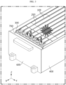
- FIG. 1 is a perspective view showing a battery module according to an embodiment of the present disclosure.
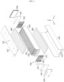
- FIG. 2 is an exploded view showing a partial configuration of a battery module according to an embodiment of the present disclosure.
- FIG. 3 is a view showing a partial configuration of a battery module according to an embodiment of the present disclosure.
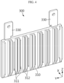
- FIG. 4 is a view showing a bus bar frame assembly 300 of a battery module according to an embodiment of the present disclosure.
- a battery module according to an embodiment of the present disclosure may be configured to include a frame 400, a battery cell 100, a bus bar frame assembly 300, and a fire-resistant coating layer 900.
- the frame 400 may include an upper frame 420 and a lower frame 410.
- the lower frame may include a bottom plate and a pair of side plates extending from the bottom plate.
- the lower frame may form an interior space.
- the upper frame 420 and the lower frame 410 may be coupled by welding.
- the upper frame 420 may be coupled to a pair of side plates of the lower frame 410.
- the frame 400 may be formed integrally.
- the frame 400 may be configured in a rectangular parallelepiped shape.
- the frame 400 may provide a space therein.
- the frame 400 may form the exterior of the battery module.
- the frame 400 may extend long in the front-rear direction or the X-axis direction.
- the frame 400 may be configured to be open in the front-rear direction or the X-axis direction.
- a plurality of battery cells 100 may be configured to be accommodated in the interior space provided by the frame 400.
- each battery cell 100 may mean a secondary battery.
- Each battery cell 100 may include a body 110 and an electrode lead 120 that protrudes in the front-rear direction of the body 110 or in the X-axis direction and -X-axis direction.
- the battery cell 100 may include an electrode assembly, an electrolyte, and a battery case. And at this time, the electrode assembly, the electrolyte, and the battery case may constitute the body 110.
- the battery cell 100 may be a pouch-type secondary battery.
- the plurality of battery cells 100 may generate heat while charging or discharging.
- the plurality of battery cells 100 may function as a heat source.
- the plurality of battery cells 100 may form a battery module.
- the battery module may be configured to store and release energy by including one or more battery cells 100.
- the plurality of battery cells 100 may be disposed or stacked in the left-right direction or the Y-axi
- the bus bar frame assembly 300 may be located in front of the plurality of battery cells 100. Also, each electrode lead 120 of the plurality of battery cells 100 may be electrically connected to the bus bar frame assembly 300.
- the busbar frame assembly 300 may be configured to include a frame body 310, a bus bar 320, and a module terminal 330.
- the frame body 310 may be configured to cover the front side of the plurality of battery cells 100.
- the bus bar 320 may be provided, coupled, or fastened to the front surface of the frame body 310.
- the bus bar 320 may be configured in plurality.
- the module terminal 330 may be electrically connected to the bus bar 320.
- the module terminal 330 may function as an input/output terminal of the battery module.
- the frame body 310 may include a slit 311 formed long in the vertical direction or the Z-axis direction.
- the slit 311 may be configured to penetrate the frame body 310 in the front-rear direction or the X-axis direction.
- the slit 311 may be formed in plurality and may be located along the left-right direction or the Y-axis direction.
- Each electrode lead 120 of the plurality of battery cells 100 may pass through the slit 311.
- the electrode lead 120 may pass through the slit 311 and then be electrically connected to the bus bar 320 provided on the front surface of the frame body 310.
- the bus bar frame assembly 300 may be formed in a pair.
- the bus bar frame assembly 300 may be provided on a front side and a rear side of the plurality of battery cells 100, respectively.
- the fire-resistant coating layer 900 may be provided on each of the plurality of battery cells 100.
- the fire-resistant coating layer 900 may be provided on at least a portion of each battery cell 100 and may have fire resistance.
- the fire-resistant coating layer 900 may be made of a material such as epoxy, non-flammable PCM, FPC 5060, Locitite EA9400, or ceramic.
- the fire-resistant coating layer 900 may be formed by spraying onto the battery cell 100 in liquid form. At this time, the fire-resistant coating layer 900 may be configured to form a thickness of about 0.05 to 2.2 mm.
- the battery cell 100 may be safely protected even if exposed to flame or venting gas (g).
- flame or venting gas (g) may be transferred to the adjacent battery cell 100.
- the fire-resistant coating layer 900 may protect the battery cell 100 from the flame or venting gas (g). Therefore, even if a thermal event occurs in the battery cell 100, heat propagation to other battery cells 100 may be effectively suppressed, delayed, or prevented. As a result, the thermal safety of the battery module may be improved.
- a battery module may be configured to include a barrier 200, an end plate 600, an insulating sheet 700, or a resin 800.
- the barrier 200 may be configured in a rectangular shape.
- the barrier 200 may extend in the front-rear direction or the X-axis direction.
- the barrier 200 may be provided in plurality.
- Each barrier 200 may be disposed between a plurality of battery cells 100.
- the barrier 200 may be disposed or stacked in the left-right direction or the Y-axis direction.
- a front side and a rear side of the barrier 200 may be contacted, coupled, fastened, inserted, or attached to the bus bar frame assembly 300, respectively.
- the barrier 200 may be composed of one part or a plurality of parts. When the barrier 200 is composed of a plurality of parts, it may be referred to as a barrier assembly 200.
- the barrier 200 may suppress, delay, or prevent flame or venting gas (g) from propagating in the left-right direction or the Y-axis direction.
- the barrier 200 may be made of a material that is not easily damaged even when exposed to flame or venting gas (g).
- the end plate 600 may be formed in a pair.
- the end plate 600 may be provided on a front side and a rear side of the plurality of battery cells 100, respectively.
- the end plate 600 may be fastened, coupled, or welded to a front side or a rear side of the frame 400, respectively.
- the end plate 600 may be fastened, coupled, or welded to an open end of the frame 400, respectively.
- the frame 400 may be internally sealed by being fastened, coupled, or welded to the end plate 600.
- the insulating sheet 700 may be configured to be positioned between the end plate 600 and the bus bar frame assembly 300.
- the insulating sheet 700 may electrically separate the end plate 600 from the bus bar frame assembly 300.
- the insulating sheet 700 may be configured in a pair.
- the insulating sheet 700 may be provided between the front side end plate 600 and the front side bus bar frame assembly 300 and between the rear side end plate 600 and the rear side bus bar frame assembly 300, respectively.
- the resin 800 may be configured to be formed inside the frame 400.
- the resin 800 may be configured to be positioned between the plurality of battery cells 100 and the lower frame 410.
- the resin 800 may be configured to be positioned between the plurality of battery cells 100 and the upper frame 420.
- the resin 800 may be configured to be positioned between the plurality of barriers 200 and the lower frame 410.
- the resin 800 may be configured to be positioned between the plurality of barriers 200 and the upper frame 420.
- the resin 800 may fix the positions of the plurality of battery cells 100 or the plurality of barriers 200.
- the resin 800 may cool the plurality of battery cells 100 by transferring heat generated from the plurality of battery cells 100 to the frame 400.
- the resin 800 may be injected into the interior of the frame 400 through holes 411, 421 of the upper frame 420 and the lower frame 410.
- flame or venting gas (g) generated inside the battery module may be discharged to the outside through the holes 411, 421.
- a buffer pad 500 may be disposed between the outermost barrier 200 and the lower frame 410.
- the buffer pad 500 may be disposed between the outermost battery cell 100 and the lower frame 410.
- the buffer pad 500 may be configured in a pair. When swelling occurs from the plurality of battery cells 100, the buffer pad 500 may stably support the plurality of battery cells 100 by being elastically deformed.
- the buffer pad 500 may be made of silicone material.
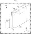
- FIG. 5 is a view showing a battery cell 100 of a battery module according to an embodiment of the present disclosure.
- FIG. 6 is a view showing a portion of the cross-sectional configuration taken along the cutting line A-A' in FIG. 1 .
- FIG. 7 is a view showing a modified example of the cross-sectional configuration taken along the cutting line A-A' in FIG. 1 .
- the battery cell 100 of the battery module according to an embodiment of the present disclosure may further include a front terrace portion 130 extending forward from the body 110 and surrounding the electrode lead 120, wherein the coating layer 900 may be configured to include a first coating layer 901 covering the front terrace portion 130 and the electrode lead 120.
- Each battery cell 100 may include a sealing portion 140 extending from the body 110.
- the sealing portion may be formed along the circumference of the body 110.
- the sealing portion protruding forward from the body 110 may be referred to as the front terrace portion 130.
- the sealing portion protruding upward from the body 110 may be referred to as an upper sealing portion 140.
- the sealing portion protruding rearward from the body 110 may be referred to as a rear terrace portion 130.
- the upper sealing portion 140 may be configured to be folded and fixed to the body by an adhesive member 150.
- the front terrace portion 130 and the rear terrace portion 130 may each be configured to surround the electrode lead 120.
- the first coating layer 901 may be configured to surround the circumference of the terrace portion 130. Alternatively, the first coating layer 901 may be configured to cover both sides of the terrace portion 130. In addition, the first coating layer 901 may be configured to extend to surround the portion of the electrode lead 120 adjacent to the terrace portion 130.
- the terrace portion 130 which can be easily damaged from flame or venting gas (g), may be protected.
- the propagation of thermal events may be effectively suppressed, delayed, or prevented.
- the first coating layer 901 may extend to the portion of the electrode lead 120 adjacent to the terrace portion 130, thereby preventing flame or venting gas (g) from penetrating between the terrace portion 130 and the electrode lead 120. As a result, the thermal safety of the battery module may be further improved.
- flame or venting gas (g) generated inside the battery cell 100 may be suppressed from being discharged to the front and rear sides.
- FIG. 8 is a view showing a modified example of the cross-sectional configuration taken along the cutting line A-A' in FIG. 1 .
- the fire-resistant coating layer 900 of the battery module may be configured to include a second coating layer 902 covering at least a portion of the rear surface of the bus bar frame assembly 300.
- the first coating layer 901 and the second coating layer 902 may be configured separately or continuously.
- the bus bar frame assembly 300 may be protected from flame or venting gas (g).
- the frame body 310 may be made of a plastic material. For this reason, when the frame body 310 is exposed to flame or venting gas (g), the frame body 310 may be damaged. Since the second coating layer 902 covers the rear surface of the frame body 310, the fire resistance of the frame body 310 may be improved.
- FIG. 9 is a view showing a modified example of the cross-sectional configuration taken along the cutting line A-A' in FIG. 1 .
- the bus bar frame assembly 300 of the battery module may include a slit 311, wherein the electrode lead 120 may pass through the slit 311, wherein the second coating layer 902 may be configured to extend to cover between the slit 311 and the electrode lead 120.
- the slit 311 may be formed in the vertical direction or the Z-axis direction.
- the slit 311 may penetrate the frame body 310.
- the second coating layer 902 may cover between the slit 311 and the electrode lead 120, and may be configured to extend along the circumference of the electrode lead 120.
- FIG. 10 is a view showing a modified example of the cross-sectional configuration taken along the cutting line A-A' in FIG. 1 .
- the coating layer 900 of the battery module according to an embodiment of the present disclosure may be configured to further include a third coating layer 903 extending from the second coating layer 902 and covering the front surface of the bus bar frame assembly 300.
- the third coating layer 903 may be configured to cover the front surface of the frame body 310. In addition, the third coating layer 903 may be configured to cover the portion of the electrode lead 120 passing through the slit 311. Also, the third coating layer 903 may be configured to cover the bus bar 320 electrically connected to the electrode lead 120.
- the frame 400 of the battery module according to an embodiment of the present disclosure may be configured to be open forward.
- the battery module according to an embodiment of the present disclosure may include an end plate 600 located in front of the bus bar frame assembly 300 and coupled to the front side or an open end of the frame 400.
- the end plate 600 and the insulating sheet 700 may be positioned to cover the frame body 310 or the slit 311.
- the insulating sheet 700 or the end plate 600 may suppress, block, delay, or reduce damage caused by flame or venting gas (g).
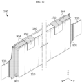
- FIG. 11 is a view showing a battery cell 100 of a battery module according to an embodiment of the present disclosure.
- FIG. 12 is a view showing a modified example of a battery cell 100 of a battery module according to an embodiment of the present disclosure.
- FIG. 13 is a view showing venting of a battery cell 100 of a battery module according to an embodiment of the present disclosure.
- the battery cell 100 of the battery module according to an embodiment of the present disclosure may be configured to include an upper sealing portion 140 extending upward from the body 110.
- the coating layer 900 may be configured to include a fourth coating layer 904 covering at least a portion of the upper sealing portion 140.
- the fourth coating layer 904 may be configured to be separated from or continuous with the first coating layer 901.
- the fourth coating layer 904 may be configured to extend from the first coating layer 901 to be formed on the front side of the upper sealing portion 140.
- flame or venting gas (g) when flame or venting gas (g) is generated in the battery cell 100, it may be suppressed from being ejected toward the first coating layer 901 and the fourth coating layer 904. Accordingly, flame or venting gas (g) may be induced to be ejected upward from near the center of the battery cell 100. As a result, venting control may be facilitated and thermal stability of the battery module may be improved.
- the battery cell 100 of the battery module may further include an adhesive member 150 for folding and fixing the upper sealing portion 140, and the fourth coating layer 904 may be configured to extend to cover at least a portion of the adhesive member 150.
- the upper sealing portion 140 may be configured to be folded and fixed to the body 110 by the adhesive member 150.
- the battery cell 100 may be configured to include two adhesive members 150.
- One adhesive member 150 may be disposed adjacent to the front edge of the body 110, and the other adhesive member 150 may be disposed adjacent to the rear edge.
- the fourth coating layer 904 may be configured to extend from the first coating layer 901 to a portion that may cover the adhesive member 150.
- the adhesive member 150 may not be disposed in the central portion of the body 110.
- the fourth coating layer 904 extends further to the central portion of the body 110, so that flame or venting gas (g) may be more strongly induced to be ejected upward from near the center of the battery cell 100. As a result, venting control may be facilitated and thermal stability of the battery module may be improved.
- FIG. 14 is a view showing a portion of the cross-sectional configuration taken along the cutting line A-A' in FIG. 1 .
- the battery module may be configured to further include a barrier 200 that cover the side surface of the battery cell 100 and is in close contact with the rear surface of the bus bar frame assembly 300.
- the coating layer 900 may be configured to further include a fifth coating layer 905 covering the rear surface of the bus bar frame assembly 300 and the side surface of the barrier 200 adjacent to the rear surface of the bus bar frame assembly 300.
- the fifth coating layer 905 may cover the exposed front edge of the barrier 200.
- the fifth coating layer 905 may be separated from or continuous with the second coating layer 902.
- the fifth coating layer 905 may be configured to extend in the vertical direction or the Z-axis direction.
- the gap between the barrier 200 and the frame body 310 may be sealed. Accordingly, the propagation of flame or venting gas (g) may be suppressed, blocked, delayed, or reduced.
- the front edge of the barrier 200 may not be exposed to flame or venting gas (g). As a result, the heat resistance or fire resistance of the barrier 200 may be stably maintained.
- FIG. 15 is a view showing a modified example of the cross-sectional configuration taken along the cutting line A-A' in FIG. 1 .
- the frame body 310 of the battery module may include a slot 312 protruding rearward.
- the slot 312 may extend long along the vertical direction or the Z-axis direction.
- the barrier 200 may be fitted or inserted into the slot 312.
- the fifth coating layer 905 may coat the space between the slot 312 and the side surface of the barrier 200.
- the fifth coating layer 905 may be configured to extend along the slot 312 in the vertical direction or the Z-axis direction.
- the gap between the slot 312 and the barrier 200 may be sealed. Accordingly, the propagation of flame or venting gas (g) may be suppressed, blocked, delayed, or reduced.
- the front edge of the barrier 200 may not be exposed to flame or venting gas (g). As a result, the heat resistance or fire resistance of the barrier 200 may be stably maintained.
- FIG. 16 is a view showing a bus bar frame assembly 300 of a battery module according to an embodiment of the present disclosure.
- FIG. 17 is a view showing a modified example of the cross-sectional configuration taken along the cutting line A-A' in FIG. 1 .
- the bus bar frame assembly 300 of the battery module according to an embodiment of the present disclosure may be configured to have a hole 313 formed long in the vertical direction.
- the battery module according to an embodiment of the present disclosure may be configured to further include the barrier 200 covering the side surface of the battery cell 100 and penetrating the hole 313 of the bus bar frame assembly 300.
- the coating layer 900 may be configured to further include a sixth coating layer 906 covering the rear surface of the bus bar frame assembly 300 and the side surface of the barrier 200 adjacent to the rear surface of the bus bar frame assembly 300.
- the hole 313 may be configured to penetrate the frame body 313.
- the hole 313 may extend in the vertical direction or the Z-axis direction.
- the hole 313 may be formed larger than the slit 312.
- the hole 313 may be formed longer than the slit 312.
- the hole 313 may be formed in plurality, and the plurality of holes 313 and the plurality of slits 312 may be arranged alternately.
- the barrier 200 may be inserted into the hole 313 or positioned to pass through the hole 313.
- the sixth coating layer 906 may be separated from or continuous with the second coating layer 902.
- the sixth coating layer 906 may be configured to extend in the vertical direction or the Z-axis direction.
- the sixth coating layer 906 may be configured to extend along the circumference of the hole 313 or the barrier 200.
- the gap between the barrier 200 and the hole 313 may be sealed. Accordingly, the propagation of flame or venting gas (g) may be suppressed, blocked, delayed, or reduced.
- the front edge of the barrier 200 may not be exposed to flame or venting gas (g). As a result, the heat resistance or fire resistance of the barrier 200 may be stably maintained.
- the sixth coating layer 906 of the battery module may be configured to extend to cover between the hole 313 and the barrier 200.
- the sixth coating layer 906 may cover between the hole 313 and the barrier 200 and may be configured to extend along the circumference of the hole 313 or the barrier 200.
- the coating layer 900 of the battery module may be configured to further include a seventh coating layer 907 extending from the sixth coating layer 906 and covering the front surface of the bus bar frame assembly 300.
- the seventh coating layer 907 may be separated from or continuous with the third coating layer 903.
- the seventh coating layer 907 may be configured to extend in the vertical direction or the Z-axis direction.
- the seventh coating layer 907 may be configured to extend along the circumference of the hole 313.
- the seventh coating layer 907 may be configured to cover the front surface of the frame body 310. In addition, the seventh coating layer 907 may be configured to cover the portion of the barrier 200 passing through the hole 313. Also, the seventh coating layer 907 may be configured to cover the bus bar 320 electrically connected to the electrode lead 120.
- FIG. 18 is a view showing a barrier 200a and a battery cell 100 of a battery module according to another embodiment of the present disclosure.
- FIG. 19 is a view showing coupling of a barrier 200a and a battery cell 100 of a battery module according to another embodiment of the present disclosure.
- FIG. 20 is a front view showing coupling of a barrier 200a and a battery cell 100 of a battery module according to another embodiment of the present disclosure.
- a battery module according to another embodiment of the present disclosure may include a barrier 200a made of a single material.
- the barrier 200a may be configured to have a corrugated cardboard shape, corrugated cardboard structure, or corrugated structure.
- the barrier 200a may be formed of a paper having fire resistance.
- the barrier 200a may be configured to include a pair of paper sheets and a corrugated paper sheet adhered between the pair of paper sheets.
- the barrier 200a may be formed in a corrugated structure with peaks and valleys.
- the plurality of battery cells 100 may be disposed to be positioned in the peak and the valley, respectively.
- the plurality of battery cells 100 and the barrier 200a may be configured to be in close contact.
- the length of the barrier 200a in the front-rear direction or the X-axis direction may be configured to be longer than the length of the body 110 of the battery cell 100 in the front-rear direction or the X-axis direction.
- the barrier 200a may cover the entire side surface of the battery cell 100 and may be configured to cover at least a portion of the electrode lead 120.
- the front edge or rear edge of the barrier 200a may be in close contact with, contacted to, coupled to, fastened to, or inserted into the bus bar frame assembly 300.
- the barrier 200a has a corrugated cardboard structure and thus may be configured to be deformable in the left-right direction or the Y-axis direction.
- the battery cell 100 may be stably supported by being compressed in the left-right direction or the Y-axis direction.
- a battery pack according to the present disclosure may include two or more battery modules according to the present disclosure described above.
- the battery pack according to the present disclosure may further include various other components in addition to the battery module, for example, components of a battery pack known at the time of filing of the present disclosure, such as a BMS, a bus bar, a pack case, a relay, a current sensor, or the like.
- components of a battery pack known at the time of filing of the present disclosure such as a BMS, a bus bar, a pack case, a relay, a current sensor, or the like.
- a vehicle according to the present disclosure may include two or more battery modules according to the present disclosure described above.
- the battery module according to the present disclosure may be applied to vehicles such as electric vehicles or hybrid vehicles. That is, the vehicle according to the present disclosure may include a battery module according to the present disclosure, or a battery pack according to the present disclosure.
- the vehicle according to the present disclosure may further include various other components included in the vehicle in addition to this battery module or battery pack.
- the vehicle according to the present disclosure may further include a vehicle body, a motor, a control device such as an electronic control unit (ECU), or the like in addition to the battery module according to the present disclosure.
- ECU electroniceeee control unit
Landscapes
- Chemical & Material Sciences (AREA)
- Chemical Kinetics & Catalysis (AREA)
- General Chemical & Material Sciences (AREA)
- Electrochemistry (AREA)
- Engineering & Computer Science (AREA)
- Aviation & Aerospace Engineering (AREA)
- Organic Chemistry (AREA)
- Wood Science & Technology (AREA)
- Materials Engineering (AREA)
- Life Sciences & Earth Sciences (AREA)
- Manufacturing & Machinery (AREA)
- Battery Mounting, Suspending (AREA)
- Connection Of Batteries Or Terminals (AREA)
Abstract
Description
- The present disclosure relates to a battery module.
- The present application claims priority to
Korean Patent Application No. 10-2022-0166949 filed on December 2, 2022 Korean Patent Application No. 10-2023-0042346 filed on March 30, 2023 - As the demand for portable electronic products such as laptops, video cameras, and mobile phones has rapidly increased in recent years and the commercialization of robots, electric vehicles, and the like has begun in earnest, research on high-performance secondary batteries capable of repeated charge/discharge has been actively conducted.
- Currently commercialized secondary batteries include nickel cadmium batteries, nickel hydride batteries, nickel zinc batteries, lithium secondary batteries, and the like. In particular, lithium secondary batteries are in the spotlight because they have almost no memory effect compared to nickel-based secondary batteries and thus have advantages of free charge/discharge, very low self-discharge rate, and high energy density.
- Such lithium secondary batteries mainly use a lithium-based oxide and a carbon material as a positive electrode active material and a negative electrode active material, respectively. Lithium secondary batteries include an electrode assembly in which a positive electrode plate and a negative electrode plate coated with the positive electrode active material and the negative electrode active material, respectively, are disposed with a separator therebetween, and an exterior material that seals and accommodates the electrode assembly together with an electrolyte, that is, a battery case.
- In general, lithium secondary batteries may be classified into can-type secondary batteries in which electrode assemblies are embedded in a metal can and pouch-type secondary batteries in which electrode assemblies are embedded in a pouch of aluminum laminate sheets, depending on the shape of an exterior material.
- Recently, secondary batteries have been widely used for driving or energy storage not only in small devices such as portable electronic devices, but also in medium/large devices such as electric vehicles and energy storage systems (ESSs). These secondary batteries are accommodated together inside a module case in a state where a plurality of secondary batteries are electrically connected, which may form one battery module. In addition, such a battery module may be connected in plurality to form one battery pack.
- However, when a plurality of secondary batteries (battery cells) or a plurality of battery modules are concentrated in a narrow space as described above, they may be vulnerable to thermal events. In particular, when an event such as thermal runaway occurs in any one of the battery cells, high temperature gas, flame, heat, or the like may be generated. If such gas, flame, heat, or the like is transferred to other battery cells included in the same battery module, an explosive chain reaction situation such as thermal propagation may occur. In addition, this chain reaction may cause not only an accident such as fire or explosion in the corresponding battery module, but also fire or explosion in other battery modules.
- Moreover, in the case of medium/large-sized devices such as electric vehicles, a large number of battery cells and battery modules may be included to increase output and/or capacity, thereby further increasing the risk of thermal chain reaction. In addition, in the case of a battery pack mounted on an electric vehicle, there may be a user such as a driver in the vicinity thereof. Therefore, if a thermal event occurring in a specific battery module is not properly controlled and a chain reaction occurs, it may cause not only significant property damage but also loss of life.
- The present disclosure is designed to solve the above-described problems and other problems.
- Another object of the present disclosure may be to provide a battery module capable of suppressing heat propagation.
- Still another object of the present disclosure may be to provide a battery module capable of maintaining safety even when exposed to flame or venting gas.
- A battery module according to an embodiment of the present disclosure may include a frame providing an interior space; a battery cell accommodated inside the frame and having a body and an electrode lead protruding toward the front of the body; a bus bar frame assembly located in front of the battery cell and electrically connected to the electrode lead; and a fire-resistant coating layer provided on at least a portion of the battery cell and having fire resistance.
- In addition, the battery cell may further include a front terrace portion extending forward from the body and surrounding the electrode lead, wherein the coating layer may include a first coating layer covering the front terrace portion and the electrode lead.
- In addition, the fire-resistant coating layer may include a second coating layer covering at least a portion of the rear surface of the bus bar frame assembly.
- In addition, the bus bar frame assembly may have a slit, wherein the electrode lead may pass through the slit, and the second coating layer may extend to cover between the slit and the electrode lead.
- In addition, the coating layer may further include a third coating layer extending from the second coating layer and covering the front surface of the bus bar frame assembly.
- In addition, the frame may be open forward, and the battery module may further include an end plate located in front of the bus bar frame assembly and coupled to the front side of the frame.
- In addition, the battery cell may further include an upper sealing portion extending upward from the body, wherein the coating layer may include a fourth coating layer covering at least a portion of the upper sealing portion.
- In addition, the battery cell may further include an adhesive member for folding and fixing the upper sealing portion, wherein the fourth coating layer may extend to cover the adhesive member.
- In addition, the battery module may further include a barrier that covers the side surface of the battery cell and is in close contact with the rear surface of the bus bar frame assembly, wherein the coating layer may further include a fifth coating layer covering the rear surface of the bus bar frame assembly and the side surface of the barrier adjacent to the rear surface.
- In addition, the bus bar frame assembly may have a hole formed long in the vertical direction, wherein the battery module may further include a barrier that covers the side surface of the battery cell and penetrates the hole of the bus bar frame assembly, and the coating layer may further include a sixth coating layer covering the rear surface of the bus bar frame assembly and the side surface of the barrier adjacent to the rear surface.
- A battery pack according to an embodiment of the present disclosure includes a battery module of the present disclosure.
- A vehicle according to an embodiment of the present disclosure includes a battery module of the present disclosure.
- According to at least one of the embodiments of the present disclosure, a battery module capable of suppressing heat propagation may be provided.
- According to at least one of the embodiments of the present disclosure, a battery module including a fire-resistant coating layer capable of protecting a bus bar frame assembly from flame or venting gas may be provided.
- According to at least one of the embodiments of the present disclosure, a battery module including a fire-resistant coating layer capable of maintaining the function of a barrier that may suppress heat propagation may be provided.
- According to at least one of the embodiments of the present disclosure, a battery module including a fire-resistant coating layer that seals a gap in a slit through which an electrode lead of a battery cell passes may be provided.
- According to at least one of the embodiments of the present disclosure, a battery module including a battery cell that may maintain safety even when exposed to flame or venting gas may be provided.
- According to at least one of the embodiments of the present disclosure, a battery module including a fire-resistant coating layer for venting control may be provided.
- The accompanying drawings illustrate a preferred embodiment of the present disclosure and together with the foregoing disclosure, serve to provide further understanding of the technical features of the present disclosure, and thus the present disclosure is not construed as being limited to the drawing.
-
FIG. 1 is a perspective view showing a battery module according to an embodiment of the present disclosure. -
FIG. 2 is an exploded view showing a partial configuration of a battery module according to an embodiment of the present disclosure. -
FIG. 3 is a view showing a partial configuration of a battery module according to an embodiment of the present disclosure. -
FIG. 4 is a view showing a bus bar frame assembly of a battery module according to an embodiment of the present disclosure. -
FIG. 5 is a view showing a battery cell of a battery module according to an embodiment of the present disclosure. -
FIG. 6 is a view showing a portion of the cross-sectional configuration taken along the cutting line A-A' inFIG. 1 . -
FIG. 7 is a view showing a modified example of the cross-sectional configuration taken along the cutting line A-A' inFIG. 1 . -
FIG. 8 is a view showing a modified example of the cross-sectional configuration taken along the cutting line A-A' inFIG. 1 . -
FIG. 9 is a view showing a modified example of the cross-sectional configuration taken along the cutting line A-A' inFIG. 1 . -
FIG. 10 is a view showing a modified example of the cross-sectional configuration taken along the cutting line A-A' inFIG. 1 . -
FIG. 11 is a view showing a battery cell of a battery module according to an embodiment of the present disclosure. -
FIG. 12 is a view showing a modified example of a battery cell of a battery module according to an embodiment of the present disclosure. -
FIG. 13 is a view showing venting of a battery cell of a battery module according to an embodiment of the present disclosure. -
FIG. 14 is a view showing a portion of the cross-sectional configuration taken along the cutting line A-A' inFIG. 1 . -
FIG. 15 is a view showing a modified example of the cross-sectional configuration taken along the cutting line A-A' inFIG. 1 . -
FIG. 16 is a view showing a bus bar frame assembly of a battery module according to an embodiment of the present disclosure. -
FIG. 17 is a view showing a modified example of the cross-sectional configuration taken along the cutting line A-A' inFIG. 1 . -
FIG. 18 is a view showing a barrier and a battery cell of a battery module according to another embodiment of the present disclosure. -
FIG. 19 is a view showing coupling of a barrier and a battery cell of a battery module according to another embodiment of the present disclosure. -
FIG. 20 is a front view showing coupling of a barrier and a battery cell of a battery module according to another embodiment of the present disclosure. - Hereinafter, preferred embodiments of the present disclosure will be described in detail with reference to the accompanying drawings. Prior to the description, it should be understood that the terms used in the specification and the appended claims should not be construed as limited to general and dictionary meanings, but interpreted based on the meanings and concepts corresponding to technical aspects of the present disclosure on the basis of the principle that the inventor is allowed to define terms appropriately for the best explanation.
- Therefore, the description proposed herein is just a preferable example for the purpose of illustrations only, not intended to limit the scope of the disclosure, so it should be understood that other equivalents and modifications could be made thereto without departing from the scope of the disclosure.
-
FIG. 1 is a perspective view showing a battery module according to an embodiment of the present disclosure.FIG. 2 is an exploded view showing a partial configuration of a battery module according to an embodiment of the present disclosure.FIG. 3 is a view showing a partial configuration of a battery module according to an embodiment of the present disclosure.FIG. 4 is a view showing a busbar frame assembly 300 of a battery module according to an embodiment of the present disclosure. Referring toFIGS. 1 to 4 , a battery module according to an embodiment of the present disclosure may be configured to include aframe 400, abattery cell 100, a busbar frame assembly 300, and a fire-resistant coating layer 900. - The
frame 400 may include anupper frame 420 and alower frame 410. The lower frame may include a bottom plate and a pair of side plates extending from the bottom plate. The lower frame may form an interior space. Theupper frame 420 and thelower frame 410 may be coupled by welding. Theupper frame 420 may be coupled to a pair of side plates of thelower frame 410. Alternatively, theframe 400 may be formed integrally. Theframe 400 may be configured in a rectangular parallelepiped shape. Also, theframe 400 may provide a space therein. Theframe 400 may form the exterior of the battery module. And, theframe 400 may extend long in the front-rear direction or the X-axis direction. In addition, theframe 400 may be configured to be open in the front-rear direction or the X-axis direction. - A plurality of
battery cells 100 may be configured to be accommodated in the interior space provided by theframe 400. Here, eachbattery cell 100 may mean a secondary battery. Eachbattery cell 100 may include abody 110 and anelectrode lead 120 that protrudes in the front-rear direction of thebody 110 or in the X-axis direction and -X-axis direction. Thebattery cell 100 may include an electrode assembly, an electrolyte, and a battery case. And at this time, the electrode assembly, the electrolyte, and the battery case may constitute thebody 110. Thebattery cell 100 may be a pouch-type secondary battery. The plurality ofbattery cells 100 may generate heat while charging or discharging. The plurality ofbattery cells 100 may function as a heat source. The plurality ofbattery cells 100 may form a battery module. The battery module may be configured to store and release energy by including one ormore battery cells 100. The plurality ofbattery cells 100 may be disposed or stacked in the left-right direction or the Y-axis direction. - The bus
bar frame assembly 300 may be located in front of the plurality ofbattery cells 100. Also, eachelectrode lead 120 of the plurality ofbattery cells 100 may be electrically connected to the busbar frame assembly 300. Thebusbar frame assembly 300 may be configured to include aframe body 310, abus bar 320, and amodule terminal 330. Theframe body 310 may be configured to cover the front side of the plurality ofbattery cells 100. Thebus bar 320 may be provided, coupled, or fastened to the front surface of theframe body 310. In addition, thebus bar 320 may be configured in plurality. And, themodule terminal 330 may be electrically connected to thebus bar 320. Themodule terminal 330 may function as an input/output terminal of the battery module. Also, theframe body 310 may include aslit 311 formed long in the vertical direction or the Z-axis direction. Theslit 311 may be configured to penetrate theframe body 310 in the front-rear direction or the X-axis direction. Theslit 311 may be formed in plurality and may be located along the left-right direction or the Y-axis direction. Eachelectrode lead 120 of the plurality ofbattery cells 100 may pass through theslit 311. Theelectrode lead 120 may pass through theslit 311 and then be electrically connected to thebus bar 320 provided on the front surface of theframe body 310. The busbar frame assembly 300 may be formed in a pair. The busbar frame assembly 300 may be provided on a front side and a rear side of the plurality ofbattery cells 100, respectively. - The fire-
resistant coating layer 900 may be provided on each of the plurality ofbattery cells 100. The fire-resistant coating layer 900 may be provided on at least a portion of eachbattery cell 100 and may have fire resistance. For example, the fire-resistant coating layer 900 may be made of a material such as epoxy, non-flammable PCM, FPC 5060, Locitite EA9400, or ceramic. In addition, the fire-resistant coating layer 900 may be formed by spraying onto thebattery cell 100 in liquid form. At this time, the fire-resistant coating layer 900 may be configured to form a thickness of about 0.05 to 2.2 mm. - According to this configuration of the present disclosure, the
battery cell 100 may be safely protected even if exposed to flame or venting gas (g). Referring toFIG. 3 , when a thermal event occurs in thebattery cell 100, flame or venting gas (g) may be transferred to theadjacent battery cell 100. At this time, the fire-resistant coating layer 900 may protect thebattery cell 100 from the flame or venting gas (g). Therefore, even if a thermal event occurs in thebattery cell 100, heat propagation toother battery cells 100 may be effectively suppressed, delayed, or prevented. As a result, the thermal safety of the battery module may be improved. - Referring to
FIGS. 1 to 4 , a battery module according to an embodiment of the present disclosure may be configured to include abarrier 200, anend plate 600, an insulatingsheet 700, or aresin 800. - The
barrier 200 may be configured in a rectangular shape. Thebarrier 200 may extend in the front-rear direction or the X-axis direction. Also, thebarrier 200 may be provided in plurality. Eachbarrier 200 may be disposed between a plurality ofbattery cells 100. Thebarrier 200 may be disposed or stacked in the left-right direction or the Y-axis direction. A front side and a rear side of thebarrier 200 may be contacted, coupled, fastened, inserted, or attached to the busbar frame assembly 300, respectively. And, thebarrier 200 may be composed of one part or a plurality of parts. When thebarrier 200 is composed of a plurality of parts, it may be referred to as abarrier assembly 200. Thebarrier 200 may suppress, delay, or prevent flame or venting gas (g) from propagating in the left-right direction or the Y-axis direction. Thebarrier 200 may be made of a material that is not easily damaged even when exposed to flame or venting gas (g). - The
end plate 600 may be formed in a pair. Theend plate 600 may be provided on a front side and a rear side of the plurality ofbattery cells 100, respectively. Theend plate 600 may be fastened, coupled, or welded to a front side or a rear side of theframe 400, respectively. Alternatively, theend plate 600 may be fastened, coupled, or welded to an open end of theframe 400, respectively. Theframe 400 may be internally sealed by being fastened, coupled, or welded to theend plate 600. - The insulating
sheet 700 may be configured to be positioned between theend plate 600 and the busbar frame assembly 300. The insulatingsheet 700 may electrically separate theend plate 600 from the busbar frame assembly 300. The insulatingsheet 700 may be configured in a pair. The insulatingsheet 700 may be provided between the frontside end plate 600 and the front side busbar frame assembly 300 and between the rearside end plate 600 and the rear side busbar frame assembly 300, respectively. - The
resin 800 may be configured to be formed inside theframe 400. Theresin 800 may be configured to be positioned between the plurality ofbattery cells 100 and thelower frame 410. In addition, theresin 800 may be configured to be positioned between the plurality ofbattery cells 100 and theupper frame 420. In addition, theresin 800 may be configured to be positioned between the plurality ofbarriers 200 and thelower frame 410. In addition, theresin 800 may be configured to be positioned between the plurality ofbarriers 200 and theupper frame 420. Theresin 800 may fix the positions of the plurality ofbattery cells 100 or the plurality ofbarriers 200. In addition, theresin 800 may cool the plurality ofbattery cells 100 by transferring heat generated from the plurality ofbattery cells 100 to theframe 400. Theresin 800 may be injected into the interior of theframe 400 throughholes upper frame 420 and thelower frame 410. In addition, flame or venting gas (g) generated inside the battery module may be discharged to the outside through theholes - A
buffer pad 500 may be disposed between theoutermost barrier 200 and thelower frame 410. Alternatively, thebuffer pad 500 may be disposed between theoutermost battery cell 100 and thelower frame 410. Thebuffer pad 500 may be configured in a pair. When swelling occurs from the plurality ofbattery cells 100, thebuffer pad 500 may stably support the plurality ofbattery cells 100 by being elastically deformed. For example, thebuffer pad 500 may be made of silicone material. -
FIG. 5 is a view showing abattery cell 100 of a battery module according to an embodiment of the present disclosure.FIG. 6 is a view showing a portion of the cross-sectional configuration taken along the cutting line A-A' inFIG. 1 .FIG. 7 is a view showing a modified example of the cross-sectional configuration taken along the cutting line A-A' inFIG. 1 . Referring toFIGS. 5 to 7 , thebattery cell 100 of the battery module according to an embodiment of the present disclosure may further include afront terrace portion 130 extending forward from thebody 110 and surrounding theelectrode lead 120, wherein thecoating layer 900 may be configured to include afirst coating layer 901 covering thefront terrace portion 130 and theelectrode lead 120. - Each
battery cell 100 may include a sealingportion 140 extending from thebody 110. The sealing portion may be formed along the circumference of thebody 110. In particular, the sealing portion protruding forward from thebody 110 may be referred to as thefront terrace portion 130. Also, the sealing portion protruding upward from thebody 110 may be referred to as anupper sealing portion 140. In addition, the sealing portion protruding rearward from thebody 110 may be referred to as arear terrace portion 130. Theupper sealing portion 140 may be configured to be folded and fixed to the body by anadhesive member 150. Thefront terrace portion 130 and therear terrace portion 130 may each be configured to surround theelectrode lead 120. - The
first coating layer 901 may be configured to surround the circumference of theterrace portion 130. Alternatively, thefirst coating layer 901 may be configured to cover both sides of theterrace portion 130. In addition, thefirst coating layer 901 may be configured to extend to surround the portion of theelectrode lead 120 adjacent to theterrace portion 130. - According to this configuration of the present disclosure, the
terrace portion 130, which can be easily damaged from flame or venting gas (g), may be protected. As a result, the propagation of thermal events may be effectively suppressed, delayed, or prevented. - In addition, according to this configuration of the present disclosure, the
first coating layer 901 may extend to the portion of theelectrode lead 120 adjacent to theterrace portion 130, thereby preventing flame or venting gas (g) from penetrating between theterrace portion 130 and theelectrode lead 120. As a result, the thermal safety of the battery module may be further improved. - In addition, according to this configuration of the present disclosure, flame or venting gas (g) generated inside the
battery cell 100 may be suppressed from being discharged to the front and rear sides. -
FIG. 8 is a view showing a modified example of the cross-sectional configuration taken along the cutting line A-A' inFIG. 1 . Referring toFIG. 8 , the fire-resistant coating layer 900 of the battery module according to an embodiment of the present disclosure may be configured to include asecond coating layer 902 covering at least a portion of the rear surface of the busbar frame assembly 300. Thefirst coating layer 901 and thesecond coating layer 902 may be configured separately or continuously. - According to this configuration of the present disclosure, the bus
bar frame assembly 300 may be protected from flame or venting gas (g). For example, theframe body 310 may be made of a plastic material. For this reason, when theframe body 310 is exposed to flame or venting gas (g), theframe body 310 may be damaged. Since thesecond coating layer 902 covers the rear surface of theframe body 310, the fire resistance of theframe body 310 may be improved. -
FIG. 9 is a view showing a modified example of the cross-sectional configuration taken along the cutting line A-A' inFIG. 1 . Referring toFIG. 9 , the busbar frame assembly 300 of the battery module according to an embodiment of the present disclosure may include aslit 311, wherein theelectrode lead 120 may pass through theslit 311, wherein thesecond coating layer 902 may be configured to extend to cover between theslit 311 and theelectrode lead 120. - The
slit 311 may be formed in the vertical direction or the Z-axis direction. Theslit 311 may penetrate theframe body 310. Thesecond coating layer 902 may cover between theslit 311 and theelectrode lead 120, and may be configured to extend along the circumference of theelectrode lead 120. - According to this configuration of the present disclosure, it is possible to prevent flame or venting gas (g) from being ejected through the
slit 311 when a thermal event occurs. As a result, heat propagation may be effectively suppressed, blocked, delayed, or reduced. -
FIG. 10 is a view showing a modified example of the cross-sectional configuration taken along the cutting line A-A' inFIG. 1 . Referring toFIG. 10 , thecoating layer 900 of the battery module according to an embodiment of the present disclosure may be configured to further include athird coating layer 903 extending from thesecond coating layer 902 and covering the front surface of the busbar frame assembly 300. - The
third coating layer 903 may be configured to cover the front surface of theframe body 310. In addition, thethird coating layer 903 may be configured to cover the portion of theelectrode lead 120 passing through theslit 311. Also, thethird coating layer 903 may be configured to cover thebus bar 320 electrically connected to theelectrode lead 120. - According to this configuration of the present disclosure, it is possible to more reliably prevent flame or venting gas (g) from being ejected through the
slit 311 when a thermal event occurs. As a result, heat propagation may be effectively suppressed, blocked, delayed, or reduced. - Referring to
FIGS. 6 to 10 , theframe 400 of the battery module according to an embodiment of the present disclosure may be configured to be open forward. Also, the battery module according to an embodiment of the present disclosure may include anend plate 600 located in front of the busbar frame assembly 300 and coupled to the front side or an open end of theframe 400. Theend plate 600 and the insulatingsheet 700 may be positioned to cover theframe body 310 or theslit 311. - According to this configuration of the present disclosure, when a thermal event occurs, it is possible to prevent flame or venting gas (g) from being ejected through the
slit 311, and the insulatingsheet 700 or theend plate 600 may suppress, block, delay, or reduce damage caused by flame or venting gas (g). -
FIG. 11 is a view showing abattery cell 100 of a battery module according to an embodiment of the present disclosure.FIG. 12 is a view showing a modified example of abattery cell 100 of a battery module according to an embodiment of the present disclosure.FIG. 13 is a view showing venting of abattery cell 100 of a battery module according to an embodiment of the present disclosure. Referring toFIGS. 11 to 13 , thebattery cell 100 of the battery module according to an embodiment of the present disclosure may be configured to include anupper sealing portion 140 extending upward from thebody 110. Also, thecoating layer 900 may be configured to include afourth coating layer 904 covering at least a portion of theupper sealing portion 140. - The
fourth coating layer 904 may be configured to be separated from or continuous with thefirst coating layer 901. For example, thefourth coating layer 904 may be configured to extend from thefirst coating layer 901 to be formed on the front side of theupper sealing portion 140. - According to this configuration of the present disclosure, when flame or venting gas (g) is generated in the
battery cell 100, it may be suppressed from being ejected toward thefirst coating layer 901 and thefourth coating layer 904. Accordingly, flame or venting gas (g) may be induced to be ejected upward from near the center of thebattery cell 100. As a result, venting control may be facilitated and thermal stability of the battery module may be improved. - Referring to
FIGS. 11 to 13 , thebattery cell 100 of the battery module according to an embodiment of the present disclosure may further include anadhesive member 150 for folding and fixing theupper sealing portion 140, and thefourth coating layer 904 may be configured to extend to cover at least a portion of theadhesive member 150. - The
upper sealing portion 140 may be configured to be folded and fixed to thebody 110 by theadhesive member 150. For example, thebattery cell 100 may be configured to include twoadhesive members 150. Oneadhesive member 150 may be disposed adjacent to the front edge of thebody 110, and the otheradhesive member 150 may be disposed adjacent to the rear edge. For example, thefourth coating layer 904 may be configured to extend from thefirst coating layer 901 to a portion that may cover theadhesive member 150. Theadhesive member 150 may not be disposed in the central portion of thebody 110. - According to this configuration of the present disclosure, the
fourth coating layer 904 extends further to the central portion of thebody 110, so that flame or venting gas (g) may be more strongly induced to be ejected upward from near the center of thebattery cell 100. As a result, venting control may be facilitated and thermal stability of the battery module may be improved. -
FIG. 14 is a view showing a portion of the cross-sectional configuration taken along the cutting line A-A' inFIG. 1 . Referring toFIG. 14 , the battery module according to an embodiment of the present disclosure may be configured to further include abarrier 200 that cover the side surface of thebattery cell 100 and is in close contact with the rear surface of the busbar frame assembly 300. Also, thecoating layer 900 may be configured to further include afifth coating layer 905 covering the rear surface of the busbar frame assembly 300 and the side surface of thebarrier 200 adjacent to the rear surface of the busbar frame assembly 300. Thefifth coating layer 905 may cover the exposed front edge of thebarrier 200. Thefifth coating layer 905 may be separated from or continuous with thesecond coating layer 902. Thefifth coating layer 905 may be configured to extend in the vertical direction or the Z-axis direction. - According to this configuration of the present disclosure, the gap between the
barrier 200 and theframe body 310 may be sealed. Accordingly, the propagation of flame or venting gas (g) may be suppressed, blocked, delayed, or reduced. - In addition, according to this configuration of the present disclosure, the front edge of the
barrier 200 may not be exposed to flame or venting gas (g). As a result, the heat resistance or fire resistance of thebarrier 200 may be stably maintained. -
FIG. 15 is a view showing a modified example of the cross-sectional configuration taken along the cutting line A-A' inFIG. 1 . Referring toFIG. 15 , theframe body 310 of the battery module according to an embodiment of the present disclosure may include aslot 312 protruding rearward. Theslot 312 may extend long along the vertical direction or the Z-axis direction. Thebarrier 200 may be fitted or inserted into theslot 312. In addition, thefifth coating layer 905 may coat the space between theslot 312 and the side surface of thebarrier 200. Thefifth coating layer 905 may be configured to extend along theslot 312 in the vertical direction or the Z-axis direction. - According to this configuration of the present disclosure, the gap between the
slot 312 and thebarrier 200 may be sealed. Accordingly, the propagation of flame or venting gas (g) may be suppressed, blocked, delayed, or reduced. - In addition, according to this configuration of the present disclosure, the front edge of the
barrier 200 may not be exposed to flame or venting gas (g). As a result, the heat resistance or fire resistance of thebarrier 200 may be stably maintained. -
FIG. 16 is a view showing a busbar frame assembly 300 of a battery module according to an embodiment of the present disclosure.FIG. 17 is a view showing a modified example of the cross-sectional configuration taken along the cutting line A-A' inFIG. 1 . Referring toFIGS. 16 and17 , the busbar frame assembly 300 of the battery module according to an embodiment of the present disclosure may be configured to have ahole 313 formed long in the vertical direction. Also, the battery module according to an embodiment of the present disclosure may be configured to further include thebarrier 200 covering the side surface of thebattery cell 100 and penetrating thehole 313 of the busbar frame assembly 300. In addition, thecoating layer 900 may be configured to further include asixth coating layer 906 covering the rear surface of the busbar frame assembly 300 and the side surface of thebarrier 200 adjacent to the rear surface of the busbar frame assembly 300. - The
hole 313 may be configured to penetrate theframe body 313. Thehole 313 may extend in the vertical direction or the Z-axis direction. Thehole 313 may be formed larger than theslit 312. In addition, thehole 313 may be formed longer than theslit 312. Thehole 313 may be formed in plurality, and the plurality ofholes 313 and the plurality ofslits 312 may be arranged alternately. - The
barrier 200 may be inserted into thehole 313 or positioned to pass through thehole 313. Thesixth coating layer 906 may be separated from or continuous with thesecond coating layer 902. Thesixth coating layer 906 may be configured to extend in the vertical direction or the Z-axis direction. In addition, thesixth coating layer 906 may be configured to extend along the circumference of thehole 313 or thebarrier 200. - According to this configuration of the present disclosure, the gap between the
barrier 200 and thehole 313 may be sealed. Accordingly, the propagation of flame or venting gas (g) may be suppressed, blocked, delayed, or reduced. - In addition, according to this configuration of the present disclosure, the front edge of the
barrier 200 may not be exposed to flame or venting gas (g). As a result, the heat resistance or fire resistance of thebarrier 200 may be stably maintained. - Also, according to this configuration of the present disclosure, it is possible to prevent flame or venting gas (g) from being ejected through the
hole 313 when a thermal event occurs. As a result, heat propagation may be effectively suppressed, blocked, delayed, or reduced. - Referring to
FIGS. 16 and17 , thesixth coating layer 906 of the battery module according to an embodiment of the present disclosure may be configured to extend to cover between thehole 313 and thebarrier 200. Thesixth coating layer 906 may cover between thehole 313 and thebarrier 200 and may be configured to extend along the circumference of thehole 313 or thebarrier 200. - In addition, the
coating layer 900 of the battery module according to an embodiment of the present disclosure may be configured to further include aseventh coating layer 907 extending from thesixth coating layer 906 and covering the front surface of the busbar frame assembly 300. Theseventh coating layer 907 may be separated from or continuous with thethird coating layer 903. Theseventh coating layer 907 may be configured to extend in the vertical direction or the Z-axis direction. In addition, theseventh coating layer 907 may be configured to extend along the circumference of thehole 313. - The
seventh coating layer 907 may be configured to cover the front surface of theframe body 310. In addition, theseventh coating layer 907 may be configured to cover the portion of thebarrier 200 passing through thehole 313. Also, theseventh coating layer 907 may be configured to cover thebus bar 320 electrically connected to theelectrode lead 120. - According to this configuration of the present disclosure, it is possible to more reliably prevent flame or venting gas (g) from being ejected through the
hole 313 when a thermal event occurs. As a result, heat propagation may be effectively suppressed, blocked, delayed, or reduced. -
FIG. 18 is a view showing abarrier 200a and abattery cell 100 of a battery module according to another embodiment of the present disclosure.FIG. 19 is a view showing coupling of abarrier 200a and abattery cell 100 of a battery module according to another embodiment of the present disclosure.FIG. 20 is a front view showing coupling of abarrier 200a and abattery cell 100 of a battery module according to another embodiment of the present disclosure. Referring toFIGS. 18 to 20 , a battery module according to another embodiment of the present disclosure may include abarrier 200a made of a single material. - The
barrier 200a may be configured to have a corrugated cardboard shape, corrugated cardboard structure, or corrugated structure. Thebarrier 200a may be formed of a paper having fire resistance. Thebarrier 200a may be configured to include a pair of paper sheets and a corrugated paper sheet adhered between the pair of paper sheets. Thebarrier 200a may be formed in a corrugated structure with peaks and valleys. The plurality ofbattery cells 100 may be disposed to be positioned in the peak and the valley, respectively. The plurality ofbattery cells 100 and thebarrier 200a may be configured to be in close contact. - In this case, the length of the
barrier 200a in the front-rear direction or the X-axis direction may be configured to be longer than the length of thebody 110 of thebattery cell 100 in the front-rear direction or the X-axis direction. For this reason, thebarrier 200a may cover the entire side surface of thebattery cell 100 and may be configured to cover at least a portion of theelectrode lead 120. The front edge or rear edge of thebarrier 200a may be in close contact with, contacted to, coupled to, fastened to, or inserted into the busbar frame assembly 300. - According to this configuration of the present disclosure, the
barrier 200a has a corrugated cardboard structure and thus may be configured to be deformable in the left-right direction or the Y-axis direction. As a result, when swelling occurs in thebattery cell 100, thebattery cell 100 may be stably supported by being compressed in the left-right direction or the Y-axis direction. - A battery pack according to the present disclosure may include two or more battery modules according to the present disclosure described above.
- In addition, the battery pack according to the present disclosure may further include various other components in addition to the battery module, for example, components of a battery pack known at the time of filing of the present disclosure, such as a BMS, a bus bar, a pack case, a relay, a current sensor, or the like.
- A vehicle according to the present disclosure may include two or more battery modules according to the present disclosure described above. The battery module according to the present disclosure may be applied to vehicles such as electric vehicles or hybrid vehicles. That is, the vehicle according to the present disclosure may include a battery module according to the present disclosure, or a battery pack according to the present disclosure. In addition, the vehicle according to the present disclosure may further include various other components included in the vehicle in addition to this battery module or battery pack. For example, the vehicle according to the present disclosure may further include a vehicle body, a motor, a control device such as an electronic control unit (ECU), or the like in addition to the battery module according to the present disclosure.
- Meanwhile, the terms indicating directions as used herein such as upper, lower, left, right, front, and rear are used for convenience of description only, and it is obvious to those skilled in the art that the term may change depending on the position of the stated element or an observer.
- While the present disclosure has been hereinabove described with regard to a limited number of embodiments and drawings, the present disclosure is not limited thereto and it is obvious to those skilled in the art that a variety of modifications and changes may be made thereto within the technical aspects of the present disclosure and the equivalent scope of the appended claims.
Claims (12)
- A battery module comprising:a frame providing an interior space;a battery cell accommodated inside the frame and having a body and an electrode lead protruding toward the front of the body;a bus bar frame assembly located in front of the battery cell and electrically connected to the electrode lead; anda fire-resistant coating layer provided on at least a portion of the battery cell and having fire resistance.
- The battery module according to claim 1,wherein the battery cell further comprises a front terrace portion extending forward from the body and surrounding the electrode lead,wherein the coating layer comprises a first coating layer covering the front terrace portion and the electrode lead.
- The battery module according to claim 1,
wherein the fire-resistant coating layer comprises a second coating layer covering at least a portion of the rear surface of the bus bar frame assembly. - The battery module according to claim 3,wherein the bus bar frame assembly has a slit,wherein the electrode lead passes through the slit, andthe second coating layer extends to cover between the slit and the electrode lead.
- The battery module according to claim 3,
wherein the coating layer further comprises a third coating layer extending from the second coating layer and covering the front surface of the bus bar frame assembly. - The battery module according to claim 1,wherein the frame is open forward, andthe battery module further comprises an end plate located in front of the bus bar frame assembly and coupled to the front side of the frame.
- The battery module according to claim 1,wherein the battery cell further comprises an upper sealing portion extending upward from the body,wherein the coating layer comprises a fourth coating layer covering at least a portion of the upper sealing portion.
- The battery module according to claim 7,wherein the battery cell further comprises an adhesive member for folding and fixing the upper sealing portion,wherein the fourth coating layer extends to cover the adhesive member.
- The battery module according to claim 1,which further comprises a barrier that covers the side surface of the battery cell and is in close contact with the rear surface of the bus bar frame assembly,wherein the coating layer further comprises a fifth coating layer covering the rear surface of the bus bar frame assembly and the side surface of the barrier adjacent to the rear surface.
- The battery module according to claim 1,wherein the bus bar frame assembly has a hole formed long in the vertical direction,wherein the battery module further comprises a barrier that covers the side surface of the battery cell and penetrates the hole of the bus bar frame assembly, andthe coating layer further comprises a sixth coating layer covering the rear surface of the bus bar frame assembly and the side surface of the barrier adjacent to the rear surface.
- A battery pack comprising a battery module according to any one of claims 1 to 10.
- A vehicle comprising a battery module according to any one of claims 1 to 10.
Applications Claiming Priority (3)
| Application Number | Priority Date | Filing Date | Title |
|---|---|---|---|
| KR20220166949 | 2022-12-02 | ||
| KR1020230042346A KR20240082990A (en) | 2022-12-02 | 2023-03-30 | Battery module |
| PCT/KR2023/009690 WO2024117428A1 (en) | 2022-12-02 | 2023-07-07 | Battery module |
Publications (2)
| Publication Number | Publication Date |
|---|---|
| EP4401218A1 true EP4401218A1 (en) | 2024-07-17 |
| EP4401218A4 EP4401218A4 (en) | 2025-04-16 |
Family
ID=90364382
Family Applications (1)
| Application Number | Title | Priority Date | Filing Date |
|---|---|---|---|
| EP23858419.7A Pending EP4401218A4 (en) | 2022-12-02 | 2023-07-07 | BATTERY MODULE |
Country Status (5)
| Country | Link |
|---|---|
| US (1) | US20250239694A1 (en) |
| EP (1) | EP4401218A4 (en) |
| JP (1) | JP7746566B2 (en) |
| CN (1) | CN119054137A (en) |
| WO (1) | WO2024117428A1 (en) |
Cited By (2)
| Publication number | Priority date | Publication date | Assignee | Title |
|---|---|---|---|---|
| EP4411960A4 (en) * | 2022-12-23 | 2025-05-21 | Lg Energy Solution, Ltd. | BATTERY MODULE, AND BATTERY PACK AND VEHICLE COMPRISING SAME |
| EP4517948A4 (en) * | 2022-05-25 | 2025-08-06 | Lg Energy Solution Ltd | SECONDARY BATTERY MODULE AND SECONDARY BATTERY THEREFOR |
Family Cites Families (17)
| Publication number | Priority date | Publication date | Assignee | Title |
|---|---|---|---|---|
| DE102010034825A1 (en) * | 2010-08-19 | 2012-02-23 | Li-Tec Battery Gmbh | Electrochemical energy storage |
| JP7120783B2 (en) * | 2018-03-27 | 2022-08-17 | 積水化学工業株式会社 | Thermally conductive thermal expansion member |
| KR102814054B1 (en) * | 2019-07-23 | 2025-05-29 | 에스케이온 주식회사 | Bettery module |
| US11711213B2 (en) | 2020-07-23 | 2023-07-25 | PolySign, Inc. | Master key escrow process |
| KR102851448B1 (en) * | 2020-10-27 | 2025-08-26 | 주식회사 엘지에너지솔루션 | Battery module and battery pack including the same |
| CN213816278U (en) * | 2020-10-30 | 2021-07-27 | 固德电材系统(苏州)股份有限公司 | Laminate polymer battery electricity core firebreak device and laminate polymer battery module |
| EP4269493A4 (en) * | 2020-12-25 | 2025-03-05 | Mitsubishi Materials Corporation | RESIN MOLDED BODY, BATTERY PACK |
| KR102830920B1 (en) * | 2021-01-11 | 2025-07-04 | 주식회사 엘지에너지솔루션 | Battery module having a structure capable of preventing fire and explosion, and battery pack and vehicle including the same |
| KR20220120916A (en) * | 2021-02-24 | 2022-08-31 | 주식회사 엘지에너지솔루션 | Battery module and battery pack including same |
| KR102713991B1 (en) * | 2021-05-20 | 2024-10-07 | 주식회사 엘지에너지솔루션 | Battery module with improved safety |
| ES3049763T3 (en) * | 2021-05-20 | 2025-12-18 | Lg Energy Solution Ltd | Battery module with improved safety |
| KR20220166949A (en) | 2021-06-11 | 2022-12-20 | (주)이브이패스 | A Managing System for Return Area of Electric Kickboard |
| CN113540640B (en) * | 2021-07-19 | 2023-08-04 | 远景动力技术(江苏)有限公司 | A power battery module |
| CN215527802U (en) * | 2021-07-19 | 2022-01-14 | 北京英特兰德智能科技有限公司 | UPS battery with fire prevention performance |
| CN216563355U (en) * | 2021-11-26 | 2022-05-17 | 微宏动力系统(湖州)有限公司 | Battery core, battery module and battery pack |
| CN114937830A (en) * | 2022-05-26 | 2022-08-23 | 重庆百转电动汽车电控系统有限责任公司 | Battery with fire extinguishing function |
| CN217768549U (en) * | 2022-05-26 | 2022-11-08 | 国网重庆综合能源服务有限公司 | Battery that possesses fire prevention function |
-
2023
- 2023-07-07 CN CN202380035068.0A patent/CN119054137A/en active Pending
- 2023-07-07 EP EP23858419.7A patent/EP4401218A4/en active Pending
- 2023-07-07 US US18/699,840 patent/US20250239694A1/en active Pending
- 2023-07-07 JP JP2024523965A patent/JP7746566B2/en active Active
- 2023-07-07 WO PCT/KR2023/009690 patent/WO2024117428A1/en not_active Ceased
Cited By (2)
| Publication number | Priority date | Publication date | Assignee | Title |
|---|---|---|---|---|
| EP4517948A4 (en) * | 2022-05-25 | 2025-08-06 | Lg Energy Solution Ltd | SECONDARY BATTERY MODULE AND SECONDARY BATTERY THEREFOR |
| EP4411960A4 (en) * | 2022-12-23 | 2025-05-21 | Lg Energy Solution, Ltd. | BATTERY MODULE, AND BATTERY PACK AND VEHICLE COMPRISING SAME |
Also Published As
| Publication number | Publication date |
|---|---|
| EP4401218A4 (en) | 2025-04-16 |
| US20250239694A1 (en) | 2025-07-24 |
| WO2024117428A1 (en) | 2024-06-06 |
| CN119054137A (en) | 2024-11-29 |
| JP2025501047A (en) | 2025-01-17 |
| JP7746566B2 (en) | 2025-09-30 |
Similar Documents
| Publication | Publication Date | Title |
|---|---|---|
| KR102713991B1 (en) | Battery module with improved safety | |
| KR102611921B1 (en) | Battery module and battery pack including the same | |
| KR102832690B1 (en) | Battery module with improved safety | |
| EP4250457A1 (en) | Battery module and battery pack including same | |
| EP4239768B1 (en) | Battery module with improved safety | |
| US20230318132A1 (en) | Battery module with reinforced safety | |
| US20250239694A1 (en) | Battery module | |
| EP4276997B1 (en) | Battery module having improved safety | |
| US20250105413A1 (en) | Battery submodule | |
| EP4401191B1 (en) | Battery module | |
| EP4685933A1 (en) | Battery pack | |
| KR20240082992A (en) | Battery module | |
| EP4246686A1 (en) | Battery module and battery pack comprising same | |
| KR20240082990A (en) | Battery module | |
| EP4579939A1 (en) | Battery module | |
| EP4675817A1 (en) | Battery pack | |
| EP4661179A1 (en) | Battery assembly | |
| EP4730490A1 (en) | Battery pack | |
| CN223809232U (en) | Battery assembly, battery module comprising same, battery pack and vehicle | |
| KR20240082991A (en) | Battery module | |
| CN224248776U (en) | Battery cell assembly, battery module comprising same, battery pack and vehicle | |
| EP4579911A1 (en) | Battery module, and battery pack and vehicle comprising same | |
| EP4715988A1 (en) | Battery pack | |
| US20240186641A1 (en) | Battery module with reinforced safety | |
| EP4468499A1 (en) | Battery module, and battery pack and vehicle comprising same |
Legal Events
| Date | Code | Title | Description |
|---|---|---|---|
| STAA | Information on the status of an ep patent application or granted ep patent |
Free format text: STATUS: UNKNOWN |
|
| STAA | Information on the status of an ep patent application or granted ep patent |
Free format text: STATUS: THE INTERNATIONAL PUBLICATION HAS BEEN MADE |
|
| PUAI | Public reference made under article 153(3) epc to a published international application that has entered the european phase |
Free format text: ORIGINAL CODE: 0009012 |
|
| STAA | Information on the status of an ep patent application or granted ep patent |
Free format text: STATUS: REQUEST FOR EXAMINATION WAS MADE |
|
| 17P | Request for examination filed |
Effective date: 20240307 |
|
| AK | Designated contracting states |
Kind code of ref document: A1 Designated state(s): AL AT BE BG CH CY CZ DE DK EE ES FI FR GB GR HR HU IE IS IT LI LT LU LV MC ME MK MT NL NO PL PT RO RS SE SI SK SM TR |
|
| A4 | Supplementary search report drawn up and despatched |
Effective date: 20250318 |
|
| RIC1 | Information provided on ipc code assigned before grant |
Ipc: H01M 50/249 20210101ALI20250312BHEP Ipc: H01M 50/502 20210101ALI20250312BHEP Ipc: H01M 50/211 20210101ALI20250312BHEP Ipc: H01M 50/24 20210101AFI20250312BHEP |
|
| STAA | Information on the status of an ep patent application or granted ep patent |
Free format text: STATUS: EXAMINATION IS IN PROGRESS |
|
| 17Q | First examination report despatched |
Effective date: 20250915 |
|
| DAV | Request for validation of the european patent (deleted) | ||
| DAX | Request for extension of the european patent (deleted) |