EP4401215A1 - Battery module - Google Patents
Battery module Download PDFInfo
- Publication number
- EP4401215A1 EP4401215A1 EP23864149.2A EP23864149A EP4401215A1 EP 4401215 A1 EP4401215 A1 EP 4401215A1 EP 23864149 A EP23864149 A EP 23864149A EP 4401215 A1 EP4401215 A1 EP 4401215A1
- Authority
- EP
- European Patent Office
- Prior art keywords
- battery
- battery module
- layer
- protection sheet
- assembly
- Prior art date
- Legal status (The legal status is an assumption and is not a legal conclusion. Google has not performed a legal analysis and makes no representation as to the accuracy of the status listed.)
- Granted
Links
Images
Classifications
-
- H—ELECTRICITY
- H01—ELECTRIC ELEMENTS
- H01M—PROCESSES OR MEANS, e.g. BATTERIES, FOR THE DIRECT CONVERSION OF CHEMICAL ENERGY INTO ELECTRICAL ENERGY
- H01M50/00—Constructional details or processes of manufacture of the non-active parts of electrochemical cells other than fuel cells, e.g. hybrid cells
- H01M50/20—Mountings; Secondary casings or frames; Racks, modules or packs; Suspension devices; Shock absorbers; Transport or carrying devices; Holders
- H01M50/204—Racks, modules or packs for multiple batteries or multiple cells
- H01M50/207—Racks, modules or packs for multiple batteries or multiple cells characterised by their shape
- H01M50/211—Racks, modules or packs for multiple batteries or multiple cells characterised by their shape adapted for pouch cells
-
- H—ELECTRICITY
- H01—ELECTRIC ELEMENTS
- H01M—PROCESSES OR MEANS, e.g. BATTERIES, FOR THE DIRECT CONVERSION OF CHEMICAL ENERGY INTO ELECTRICAL ENERGY
- H01M50/00—Constructional details or processes of manufacture of the non-active parts of electrochemical cells other than fuel cells, e.g. hybrid cells
- H01M50/20—Mountings; Secondary casings or frames; Racks, modules or packs; Suspension devices; Shock absorbers; Transport or carrying devices; Holders
- H01M50/218—Mountings; Secondary casings or frames; Racks, modules or packs; Suspension devices; Shock absorbers; Transport or carrying devices; Holders characterised by the material
- H01M50/22—Mountings; Secondary casings or frames; Racks, modules or packs; Suspension devices; Shock absorbers; Transport or carrying devices; Holders characterised by the material of the casings or racks
- H01M50/222—Inorganic material
- H01M50/224—Metals
-
- H—ELECTRICITY
- H01—ELECTRIC ELEMENTS
- H01M—PROCESSES OR MEANS, e.g. BATTERIES, FOR THE DIRECT CONVERSION OF CHEMICAL ENERGY INTO ELECTRICAL ENERGY
- H01M50/00—Constructional details or processes of manufacture of the non-active parts of electrochemical cells other than fuel cells, e.g. hybrid cells
- H01M50/20—Mountings; Secondary casings or frames; Racks, modules or packs; Suspension devices; Shock absorbers; Transport or carrying devices; Holders
- H01M50/218—Mountings; Secondary casings or frames; Racks, modules or packs; Suspension devices; Shock absorbers; Transport or carrying devices; Holders characterised by the material
- H01M50/22—Mountings; Secondary casings or frames; Racks, modules or packs; Suspension devices; Shock absorbers; Transport or carrying devices; Holders characterised by the material of the casings or racks
- H01M50/231—Mountings; Secondary casings or frames; Racks, modules or packs; Suspension devices; Shock absorbers; Transport or carrying devices; Holders characterised by the material of the casings or racks having a layered structure
-
- H—ELECTRICITY
- H01—ELECTRIC ELEMENTS
- H01M—PROCESSES OR MEANS, e.g. BATTERIES, FOR THE DIRECT CONVERSION OF CHEMICAL ENERGY INTO ELECTRICAL ENERGY
- H01M50/00—Constructional details or processes of manufacture of the non-active parts of electrochemical cells other than fuel cells, e.g. hybrid cells
- H01M50/20—Mountings; Secondary casings or frames; Racks, modules or packs; Suspension devices; Shock absorbers; Transport or carrying devices; Holders
- H01M50/233—Mountings; Secondary casings or frames; Racks, modules or packs; Suspension devices; Shock absorbers; Transport or carrying devices; Holders characterised by physical properties of casings or racks, e.g. dimensions
- H01M50/24—Mountings; Secondary casings or frames; Racks, modules or packs; Suspension devices; Shock absorbers; Transport or carrying devices; Holders characterised by physical properties of casings or racks, e.g. dimensions adapted for protecting batteries from their environment, e.g. from corrosion
-
- Y—GENERAL TAGGING OF NEW TECHNOLOGICAL DEVELOPMENTS; GENERAL TAGGING OF CROSS-SECTIONAL TECHNOLOGIES SPANNING OVER SEVERAL SECTIONS OF THE IPC; TECHNICAL SUBJECTS COVERED BY FORMER USPC CROSS-REFERENCE ART COLLECTIONS [XRACs] AND DIGESTS
- Y02—TECHNOLOGIES OR APPLICATIONS FOR MITIGATION OR ADAPTATION AGAINST CLIMATE CHANGE
- Y02E—REDUCTION OF GREENHOUSE GAS [GHG] EMISSIONS, RELATED TO ENERGY GENERATION, TRANSMISSION OR DISTRIBUTION
- Y02E60/00—Enabling technologies; Technologies with a potential or indirect contribution to GHG emissions mitigation
- Y02E60/10—Energy storage using batteries
Definitions
- the present disclosure relates to an electronic component, more particularly, to a battery module.
- the present application claims priority to Korean Patent Application No. 10-2022-0160259 filed on November 25, 2022 in the Republic of Korea, the disclosures of which are incorporated herein by reference.
- a portable electronic product includes a battery module to supply necessary power.
- a battery module to supply necessary power.
- ESD Electro Static Discharge
- a conductive tape or metal layer is attached to the battery module to be used as an antenna signal transmission path or an ESD grounding path.
- the thickness of the battery module increases, which violates the trend of thin design of electronic products.
- the present disclosure is designed to solve the problems of the related art, and therefore the present disclosure is directed to providing a battery module having an electrostatic protection function by providing an antenna signal transmission path or an ESD grounding path without increasing the thickness.
- a battery module includes a battery assembly and a protection assembly.
- the battery assembly has an outer surface.
- the protection assembly covers the outer surface of the battery assembly, and the protection assembly includes an adhesive layer, a support layer and a metal coating layer.
- the adhesive layer and the metal coating layer are located at opposite sides of the support layer, respectively, and the adhesive layer is adhered to the outer surface.
- the outer surface may include a first surface, a second surface, and a peripheral surface connecting the first surface and the second surface.
- the protection assembly may include a first protection sheet and a second protection sheet.
- the first protection sheet may cover the first surface and extend along the peripheral surface to cover the second surface.
- the first protection sheet may have an opening, the opening may partially expose the second surface.
- the second protection sheet may cover the first protection sheet located on the second surface and the second surface exposed by the opening.
- an edge of the first protection sheet located on the peripheral surface may match an edge of the second protection sheet.
- the metal coating layer may include a tin layer.
- the material of the support layer may include PET.
- a first thickness of the support layer may be greater than a second thickness of the adhesive layer, and the second thickness of the adhesive layer may be greater than a third thickness of the metal coating layer.
- the thickness of the metal coating layer may be greater than 0 and less than or equal to 0.004 mm.
- the battery assembly may include a support structure and at least one battery unit, the support structure may support the at least one battery unit, and the protection assembly may be at least partially in direct contact with the support structure and at least partially in direct contact with the battery unit.
- At least one free space may be provided between the support structure and the at least one battery unit.
- the at least one battery unit may include at least one soft pack battery cell.
- the protection assembly surrounds the outer surface of the battery assembly, and the protection assembly including an adhesive layer, a support layer and a metal coating layer is adhered to the outer surface of the battery assembly through the adhesive layer so that the metal coating layer is located at the outermost side of the battery module.
- the metal coating layer serves as an antenna signal transmission path or an ESD ground path, so it is not necessary to separately attach a conductive tape or metal layer to the battery module to provide an electrical path. Therefore, the battery module according to the present disclosure may have an electrostatic protection function without increasing the thickness.
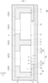
- FIG. 1 is a cross-sectional view showing a battery module according to an embodiment of the present disclosure.
- FIG. 1 is a cross-sectional view showing a battery module according to an embodiment of the present disclosure.
- a battery module 100 according to this embodiment is a battery module used, for example, in a notebook computer or other electronic products, and includes a battery assembly 110 and a protection assembly 120.
- the battery assembly 110 has an outer surface S.
- the protection assembly 120 is installed to cover the outer surface S of the battery assembly 110.
- the protection assembly 120 includes a support layer L1, an adhesive layer L2, and a metal coating layer L3, among which the adhesive layer L2 and the metal coating layer L3 are located at opposite sides of the support layer L1, respectively, and the adhesive layer L2 is adhered to the outer surface S.
- the metal coating layer L3 of the protection assembly 120 is located at the outermost side of the entire battery module 100.
- the battery assembly 110 includes a support structure 112 and at least one battery unit (two battery units 114 are shown as an example), among which the support structure 112 supports the battery unit 114.
- the support structure 112 is shown as three structures separated from each other, but the present application is not limited thereto, and the support structure 112 may actually be an integral structure.
- the battery unit 114 may be a soft pack battery cell, but is not limited thereto.
- at least one free space A is provided between the support structure 112 and the battery unit 114 so as to leave a margin necessary for thermal expansion and deformation of the battery unit 114.
- the outer surface S of the battery assembly 110 includes a first surface S1, a second surface S2, and a peripheral surface S3 connecting the first surface S1 and the second surface S2.
- One end of the support structure 112 may be regarded as the first surface S1 of the battery assembly 110, and the other end 113 of the structure 112 and the surface 115 of the battery unit 114 together constitute the second surface S2 of the battery assembly 110.
- the side surface of the support structure 112 is the peripheral surface S3 connected between the first surface S1 and the second surface S2 of the battery assembly 110.
- the protection assembly 120 is at least partially in direct contact with the support structure 112 and at least partially in direct contact with the battery unit 114.
- the protection assembly 120 includes a first protection sheet 122 and a second protection sheet 124.
- the first protection sheet 122 covers the first surface S1 and extends along the peripheral surface S3 to cover the second surface S2.
- the first protection sheet 122 has an opening 123, and the opening 123 exposes a part of the second surface S2.
- the second protection sheet 124 covers the first protection sheet 122 located on the second surface S2 and the second surface S2 exposed by the opening 123.
- the first protection sheet 122 and the second protection sheet 124 have a three-layer structure (the support layer L1, the adhesive layer L2, and the metal coating layer L3), respectively, among which the first protection sheet 122 of FIG. 1 is formed to be bent according to the shape and size of the battery assembly 110, and the second protection sheet 124 is directly adhered to the first protection sheet 122 in an unbent form. That is, the metal coating layer L3 of the first protection sheet 122 is connected to the adhesive layer L2 of the second protection sheet 124 on the second surface S2, and the second surface S2 exposed by the opening 123 is surrounded within the second protection sheet 124.
- the outermost side of the battery module 100 may serve as an antenna signal transmission path or an ESD ground path within the electronic product using the metal coating layer L3 of the protection assembly 120. Therefore, since there is no need to attach a separate conductive tape or metal layer on the battery module 100 to provide an electrical path, the battery module 100 according to this embodiment may have a static electricity protection function without increasing the thickness.
- the edge E1 of the first protection sheet 122 located on the peripheral surface S3 matches the edge E2 of the second protection sheet 124, but is not limited thereto.
- the first thickness T1 of the support layer L1 is greater than the second thickness T2 of the adhesive layer L2, and the second thickness T2 of the adhesive layer L2 is greater than the third thickness T3 of the metal coating layer L3.
- the first thickness T1 may range from 0.031 mm to 0.041 mm
- the second thickness T2 may range from 0.019 mm to 0.025 mm
- the thickness of the metal coating layer L3 (third thickness T3) is greater than 0 and less than or equal to 0.004 mm, but is not limited thereto.
- a release film (not shown) is further provided to cover the adhesive layer L2 so as to protect and maintain the bonding property.
- the support layer L1 is, for example, Mylar or other type of insulating material.
- the support layer L1 is made of black polyethylene terephthalate (black PET), for example embossing glue.
- the metal coating layer L3 may be a tin layer, but is not limited thereto.
- the protection assembly surrounds the outer surface of the battery assembly, and the protection assembly including an adhesive layer, a support layer and a metal coating layer is adhered to the outer surface of the battery assembly through the adhesive layer so that the metal coating layer is located at the outermost side of the battery module. Therefore, since the metal coating layer may be used as an antenna signal transmission path or an ESD ground path, there is no need to separately attach a conductive tape or metal layer on the battery module to provide an electrical path. Therefore, the battery module according to the present disclosure may have an electrostatic protection function without increasing the thickness.
Landscapes
- Chemical & Material Sciences (AREA)
- Chemical Kinetics & Catalysis (AREA)
- Electrochemistry (AREA)
- General Chemical & Material Sciences (AREA)
- Inorganic Chemistry (AREA)
- Battery Mounting, Suspending (AREA)
Abstract
Description
- The present disclosure relates to an electronic component, more particularly, to a battery module. The present application claims priority to
Korean Patent Application No. 10-2022-0160259 filed on November 25, 2022 - A portable electronic product includes a battery module to supply necessary power. In some electronic products, in order to arrange the structure for antenna signal transmission and ESD (Electro Static Discharge) protection in a limited space, a conductive tape or metal layer is attached to the battery module to be used as an antenna signal transmission path or an ESD grounding path. However, in this case, the thickness of the battery module increases, which violates the trend of thin design of electronic products.
- The present disclosure is designed to solve the problems of the related art, and therefore the present disclosure is directed to providing a battery module having an electrostatic protection function by providing an antenna signal transmission path or an ESD grounding path without increasing the thickness.
- A battery module according to the present disclosure includes a battery assembly and a protection assembly. The battery assembly has an outer surface. The protection assembly covers the outer surface of the battery assembly, and the protection assembly includes an adhesive layer, a support layer and a metal coating layer. The adhesive layer and the metal coating layer are located at opposite sides of the support layer, respectively, and the adhesive layer is adhered to the outer surface.
- In an embodiment of the present disclosure, the outer surface may include a first surface, a second surface, and a peripheral surface connecting the first surface and the second surface. The protection assembly may include a first protection sheet and a second protection sheet. The first protection sheet may cover the first surface and extend along the peripheral surface to cover the second surface. The first protection sheet may have an opening, the opening may partially expose the second surface. The second protection sheet may cover the first protection sheet located on the second surface and the second surface exposed by the opening.
- In an embodiment of the present disclosure, an edge of the first protection sheet located on the peripheral surface may match an edge of the second protection sheet.
- In an embodiment of the present disclosure, the metal coating layer may include a tin layer.
- In an embodiment of the present disclosure, the material of the support layer may include PET.
- In an embodiment of the present disclosure, a first thickness of the support layer may be greater than a second thickness of the adhesive layer, and the second thickness of the adhesive layer may be greater than a third thickness of the metal coating layer.
- In an embodiment of the present disclosure, the thickness of the metal coating layer may be greater than 0 and less than or equal to 0.004 mm.
- In an embodiment of the present disclosure, the battery assembly may include a support structure and at least one battery unit, the support structure may support the at least one battery unit, and the protection assembly may be at least partially in direct contact with the support structure and at least partially in direct contact with the battery unit.
- In an embodiment of the present disclosure, at least one free space may be provided between the support structure and the at least one battery unit.
- In an embodiment of the present disclosure, the at least one battery unit may include at least one soft pack battery cell.
- According to the above, in the battery module according to the present disclosure, the protection assembly surrounds the outer surface of the battery assembly, and the protection assembly including an adhesive layer, a support layer and a metal coating layer is adhered to the outer surface of the battery assembly through the adhesive layer so that the metal coating layer is located at the outermost side of the battery module. Through this, the metal coating layer serves as an antenna signal transmission path or an ESD ground path, so it is not necessary to separately attach a conductive tape or metal layer to the battery module to provide an electrical path. Therefore, the battery module according to the present disclosure may have an electrostatic protection function without increasing the thickness.
-
FIG. 1 is a cross-sectional view showing a battery module according to an embodiment of the present disclosure. - In order to understand the features and advantages of the present disclosure more clearly and easily, a detailed description is provided in conjunction with the drawings through the following embodiment.
- The present disclosure can be understood by referring to the following detailed description and the accompanying drawings, and it should be noted that for easy understanding of the present disclosure and conciseness of the drawings, the structures in the drawings are not drawn to scale. In addition, the quantity and size of each component in the drawing is only an example and does not limit the present disclosure.
-
FIG. 1 is a cross-sectional view showing a battery module according to an embodiment of the present disclosure. Referring toFIG. 1 , abattery module 100 according to this embodiment is a battery module used, for example, in a notebook computer or other electronic products, and includes abattery assembly 110 and aprotection assembly 120. Thebattery assembly 110 has an outer surface S. Theprotection assembly 120 is installed to cover the outer surface S of thebattery assembly 110. Theprotection assembly 120 includes a support layer L1, an adhesive layer L2, and a metal coating layer L3, among which the adhesive layer L2 and the metal coating layer L3 are located at opposite sides of the support layer L1, respectively, and the adhesive layer L2 is adhered to the outer surface S. In other words, the metal coating layer L3 of theprotection assembly 120 is located at the outermost side of theentire battery module 100. - Specifically, the
battery assembly 110 includes asupport structure 112 and at least one battery unit (twobattery units 114 are shown as an example), among which thesupport structure 112 supports thebattery unit 114. In the cross section ofFIG. 1 , thesupport structure 112 is shown as three structures separated from each other, but the present application is not limited thereto, and thesupport structure 112 may actually be an integral structure. In one embodiment, thebattery unit 114 may be a soft pack battery cell, but is not limited thereto. In addition, at least one free space A is provided between thesupport structure 112 and thebattery unit 114 so as to leave a margin necessary for thermal expansion and deformation of thebattery unit 114. The outer surface S of thebattery assembly 110 includes a first surface S1, a second surface S2, and a peripheral surface S3 connecting the first surface S1 and the second surface S2. One end of thesupport structure 112 may be regarded as the first surface S1 of thebattery assembly 110, and theother end 113 of thestructure 112 and thesurface 115 of thebattery unit 114 together constitute the second surface S2 of thebattery assembly 110. The side surface of thesupport structure 112 is the peripheral surface S3 connected between the first surface S1 and the second surface S2 of thebattery assembly 110. - Referring to
FIG. 1 again, theprotection assembly 120 is at least partially in direct contact with thesupport structure 112 and at least partially in direct contact with thebattery unit 114. In this embodiment, theprotection assembly 120 includes afirst protection sheet 122 and asecond protection sheet 124. Thefirst protection sheet 122 covers the first surface S1 and extends along the peripheral surface S3 to cover the second surface S2. Thefirst protection sheet 122 has anopening 123, and the opening 123 exposes a part of the second surface S2. Thesecond protection sheet 124 covers thefirst protection sheet 122 located on the second surface S2 and the second surface S2 exposed by theopening 123. Here, thefirst protection sheet 122 and thesecond protection sheet 124 have a three-layer structure (the support layer L1, the adhesive layer L2, and the metal coating layer L3), respectively, among which thefirst protection sheet 122 ofFIG. 1 is formed to be bent according to the shape and size of thebattery assembly 110, and thesecond protection sheet 124 is directly adhered to thefirst protection sheet 122 in an unbent form. That is, the metal coating layer L3 of thefirst protection sheet 122 is connected to the adhesive layer L2 of thesecond protection sheet 124 on the second surface S2, and the second surface S2 exposed by theopening 123 is surrounded within thesecond protection sheet 124. In this way, the outermost side of thebattery module 100 may serve as an antenna signal transmission path or an ESD ground path within the electronic product using the metal coating layer L3 of theprotection assembly 120. Therefore, since there is no need to attach a separate conductive tape or metal layer on thebattery module 100 to provide an electrical path, thebattery module 100 according to this embodiment may have a static electricity protection function without increasing the thickness. - In one embodiment, the edge E1 of the
first protection sheet 122 located on the peripheral surface S3 matches the edge E2 of thesecond protection sheet 124, but is not limited thereto. Also, as shown inFIG. 1 , the first thickness T1 of the support layer L1 is greater than the second thickness T2 of the adhesive layer L2, and the second thickness T2 of the adhesive layer L2 is greater than the third thickness T3 of the metal coating layer L3. In one embodiment, the first thickness T1 may range from 0.031 mm to 0.041 mm, the second thickness T2 may range from 0.019 mm to 0.025 mm, and the thickness of the metal coating layer L3 (third thickness T3) is greater than 0 and less than or equal to 0.004 mm, but is not limited thereto. In more detail, before the protection sheet (thefirst protection sheet 122 and the second protection sheet 124) is adhered thebattery assembly 110, a release film (not shown) is further provided to cover the adhesive layer L2 so as to protect and maintain the bonding property. In one embodiment, the support layer L1 is, for example, Mylar or other type of insulating material. In one embodiment, the support layer L1 is made of black polyethylene terephthalate (black PET), for example embossing glue. In one embodiment, the metal coating layer L3 may be a tin layer, but is not limited thereto. - As described above, in the battery module according to the present disclosure, the protection assembly surrounds the outer surface of the battery assembly, and the protection assembly including an adhesive layer, a support layer and a metal coating layer is adhered to the outer surface of the battery assembly through the adhesive layer so that the metal coating layer is located at the outermost side of the battery module. Therefore, since the metal coating layer may be used as an antenna signal transmission path or an ESD ground path, there is no need to separately attach a conductive tape or metal layer on the battery module to provide an electrical path. Therefore, the battery module according to the present disclosure may have an electrostatic protection function without increasing the thickness.
- The present disclosure has been described through the embodiment as described above, but is not limited thereto, and appropriate changes and modifications can be made by those skilled in the art within the range that does not deviate from the purpose of the present disclosure, and the scope of protection of the present disclosure shall be based on the appended claims.
-
- 100: battery module
- 110: battery assembly
- 112: support structure
- 113: the other end
- 114: battery unit
- 115: surface
- 120: protection assembly
- 122: first protection sheet
- 123: opening
- 124: second protection sheet
- A: free space
- E1, E2: edge
- L1: support layer
- L2: adhesive layer
- L3: metal coating layer
- S: outer surface
- S 1: first surface
- S2: second surface
- S3: peripheral surface
- T1: first thickness
- T2: second thickness
- T3: third thickness
Claims (10)
- A battery module, comprising:a battery assembly having an outer surface, anda protection assembly configured to cover the outer surface of the battery assembly and including an adhesive layer, a support layer and a metal coating layer, wherein the adhesive layer and the metal coating layer are located at opposite sides of the support layer, respectively, and the adhesive layer is adhered to the outer surface.
- The battery module according to claim 1,
wherein the outer surface includes a first surface, a second surface, and a peripheral surface connecting the first surface and the second surface, the protection assembly includes a first protection sheet and a second protection sheet, the first protection sheet covers the first surface and extends along the peripheral surface to cover the second surface, the first protection sheet has an opening, the opening partially exposes the second surface, and the second protection sheet covers the first protection sheet located on the second surface and the second surface exposed by the opening. - The battery module according to claim 2
wherein an edge of the first protection sheet located on the peripheral surface matches an edge of the second protection sheet. - The battery module according to claim 1,
wherein the metal coating layer includes a tin layer. - The battery module according to claim 1,
wherein the material of the support layer includes PET. - The battery module according to claim 1,
wherein a first thickness of the support layer is greater than a second thickness of the adhesive layer, and the second thickness of the adhesive layer is greater than a third thickness of the metal coating layer. - The battery module according to claim 1,
wherein the thickness of the metal coating layer is greater than 0 and less than or equal to 0.004 mm. - The battery module according to claim 1,
wherein the battery assembly includes a support structure and at least one battery unit, the support structure supports the at least one battery unit, and the protection assembly is at least partially in direct contact with the support structure and at least partially in direct contact with the battery unit. - The battery module according to claim 8,
wherein at least one free space is provided between the support structure and the at least one battery unit. - The battery module according to claim 8,
wherein the at least one battery unit includes at least one soft pack battery cell.
Applications Claiming Priority (2)
| Application Number | Priority Date | Filing Date | Title |
|---|---|---|---|
| KR20221060259 | 2022-11-25 | ||
| PCT/KR2023/005562 WO2024111764A1 (en) | 2022-11-25 | 2023-04-24 | Battery module |
Publications (3)
| Publication Number | Publication Date |
|---|---|
| EP4401215A1 true EP4401215A1 (en) | 2024-07-17 |
| EP4401215A4 EP4401215A4 (en) | 2025-07-02 |
| EP4401215B1 EP4401215B1 (en) | 2026-05-06 |
Family
ID=91540689
Family Applications (1)
| Application Number | Title | Priority Date | Filing Date |
|---|---|---|---|
| EP23864149.2A Active EP4401215B1 (en) | 2022-11-25 | 2023-04-24 | Battery module |
Country Status (1)
| Country | Link |
|---|---|
| EP (1) | EP4401215B1 (en) |
Family Cites Families (4)
| Publication number | Priority date | Publication date | Assignee | Title |
|---|---|---|---|---|
| JP2007323909A (en) * | 2006-05-31 | 2007-12-13 | Sanyo Electric Co Ltd | Battery pack |
| KR20220101991A (en) * | 2021-01-12 | 2022-07-19 | 주식회사 엘지에너지솔루션 | Battery module |
| CN214203848U (en) * | 2021-02-04 | 2021-09-14 | 常州宏巨电子科技有限公司 | Mobile phone battery protective film convenient for heat dissipation |
| CN216436030U (en) * | 2021-11-03 | 2022-05-03 | 惠州市豪鹏科技有限公司 | Laminate polymer battery and electronic product |
-
2023
- 2023-04-24 EP EP23864149.2A patent/EP4401215B1/en active Active
Also Published As
| Publication number | Publication date |
|---|---|
| EP4401215A4 (en) | 2025-07-02 |
| EP4401215B1 (en) | 2026-05-06 |
Similar Documents
| Publication | Publication Date | Title |
|---|---|---|
| CN111710247B (en) | Display module and display device | |
| US20100265430A1 (en) | Display device with conductive masking film for discharging static electricity | |
| US20150140362A1 (en) | Battery pack | |
| EP3998524B1 (en) | Display device | |
| CN105960157A (en) | Electromagnetic shielding protection film and FPC (flexible printed circuit) | |
| CN113411939B (en) | Display module | |
| WO2017067301A1 (en) | Display device | |
| US20110067905A1 (en) | Flexible printed circuit board and method for forming monitor | |
| CN212365388U (en) | Display module and display device | |
| US9871274B2 (en) | Secondary battery with protection circuit module with label and release sheet | |
| CN213403092U (en) | Display module and electronic equipment | |
| EP4401215B1 (en) | Battery module | |
| CN215872067U (en) | Electronic device | |
| KR102927732B1 (en) | Battery module | |
| US11765873B2 (en) | Electromagnetic shielding film, flexible circuit board and display device | |
| CN113963632A (en) | Display module and display device | |
| TW202422930A (en) | Battery module | |
| US20250358928A1 (en) | Display device | |
| KR20220101991A (en) | Battery module | |
| CN117409674A (en) | Electronic equipment | |
| TWI891706B (en) | Battery module | |
| US20080198538A1 (en) | Battery modules and housing structures thereof | |
| CN116256915A (en) | Display module and display device | |
| CN118431690B (en) | Cell components, batteries and electronic devices | |
| US12349326B2 (en) | Anti-magnetic interference component and electronic device |
Legal Events
| Date | Code | Title | Description |
|---|---|---|---|
| STAA | Information on the status of an ep patent application or granted ep patent |
Free format text: STATUS: UNKNOWN |
|
| STAA | Information on the status of an ep patent application or granted ep patent |
Free format text: STATUS: THE INTERNATIONAL PUBLICATION HAS BEEN MADE |
|
| PUAI | Public reference made under article 153(3) epc to a published international application that has entered the european phase |
Free format text: ORIGINAL CODE: 0009012 |
|
| STAA | Information on the status of an ep patent application or granted ep patent |
Free format text: STATUS: REQUEST FOR EXAMINATION WAS MADE |
|
| 17P | Request for examination filed |
Effective date: 20240322 |
|
| AK | Designated contracting states |
Kind code of ref document: A1 Designated state(s): AL AT BE BG CH CY CZ DE DK EE ES FI FR GB GR HR HU IE IS IT LI LT LU LV MC ME MK MT NL NO PL PT RO RS SE SI SK SM TR |
|
| REG | Reference to a national code |
Ref legal event code: R079 Free format text: PREVIOUS MAIN CLASS: H01M0050224000 Ipc: H01M0050240000 Ref country code: DE Ref legal event code: R079 Ref document number: 602023017080 Country of ref document: DE Free format text: PREVIOUS MAIN CLASS: H01M0050224000 Ipc: H01M0050240000 |
|
| A4 | Supplementary search report drawn up and despatched |
Effective date: 20250530 |
|
| RIC1 | Information provided on ipc code assigned before grant |
Ipc: H01M 50/211 20210101ALI20250526BHEP Ipc: H01M 50/224 20210101ALI20250526BHEP Ipc: H01M 50/231 20210101ALI20250526BHEP Ipc: H01M 50/24 20210101AFI20250526BHEP |
|
| GRAP | Despatch of communication of intention to grant a patent |
Free format text: ORIGINAL CODE: EPIDOSNIGR1 |
|
| STAA | Information on the status of an ep patent application or granted ep patent |
Free format text: STATUS: GRANT OF PATENT IS INTENDED |
|
| DAV | Request for validation of the european patent (deleted) | ||
| DAX | Request for extension of the european patent (deleted) | ||
| RIC1 | Information provided on ipc code assigned before grant |
Ipc: H01M 50/24 20210101AFI20260126BHEP Ipc: H01M 50/231 20210101ALI20260126BHEP Ipc: H01M 50/224 20210101ALI20260126BHEP Ipc: H01M 50/211 20210101ALI20260126BHEP |
|
| INTG | Intention to grant announced |
Effective date: 20260213 |
|
| GRAS | Grant fee paid |
Free format text: ORIGINAL CODE: EPIDOSNIGR3 |
|
| GRAA | (expected) grant |
Free format text: ORIGINAL CODE: 0009210 |
|
| STAA | Information on the status of an ep patent application or granted ep patent |
Free format text: STATUS: THE PATENT HAS BEEN GRANTED |
|
| AK | Designated contracting states |
Kind code of ref document: B1 Designated state(s): AL AT BE BG CH CY CZ DE DK EE ES FI FR GB GR HR HU IE IS IT LI LT LU LV MC ME MK MT NL NO PL PT RO RS SE SI SK SM TR |
|
| REG | Reference to a national code |
Ref country code: CH Ref legal event code: F10 Free format text: ST27 STATUS EVENT CODE: U-0-0-F10-F00 (AS PROVIDED BY THE NATIONAL OFFICE) Effective date: 20260506 Ref country code: GB Ref legal event code: FG4D |