EP4401213A1 - Battery sub-module - Google Patents
Battery sub-module Download PDFInfo
- Publication number
- EP4401213A1 EP4401213A1 EP23866625.9A EP23866625A EP4401213A1 EP 4401213 A1 EP4401213 A1 EP 4401213A1 EP 23866625 A EP23866625 A EP 23866625A EP 4401213 A1 EP4401213 A1 EP 4401213A1
- Authority
- EP
- European Patent Office
- Prior art keywords
- battery
- present disclosure
- bus bar
- upper case
- battery cells
- Prior art date
- Legal status (The legal status is an assumption and is not a legal conclusion. Google has not performed a legal analysis and makes no representation as to the accuracy of the status listed.)
- Pending
Links
Images





Classifications
-
- H—ELECTRICITY
- H01—ELECTRIC ELEMENTS
- H01M—PROCESSES OR MEANS, e.g. BATTERIES, FOR THE DIRECT CONVERSION OF CHEMICAL ENERGY INTO ELECTRICAL ENERGY
- H01M50/00—Constructional details or processes of manufacture of the non-active parts of electrochemical cells other than fuel cells, e.g. hybrid cells
- H01M50/20—Mountings; Secondary casings or frames; Racks, modules or packs; Suspension devices; Shock absorbers; Transport or carrying devices; Holders
- H01M50/204—Racks, modules or packs for multiple batteries or multiple cells
- H01M50/207—Racks, modules or packs for multiple batteries or multiple cells characterised by their shape
- H01M50/211—Racks, modules or packs for multiple batteries or multiple cells characterised by their shape adapted for pouch cells
-
- H—ELECTRICITY
- H01—ELECTRIC ELEMENTS
- H01M—PROCESSES OR MEANS, e.g. BATTERIES, FOR THE DIRECT CONVERSION OF CHEMICAL ENERGY INTO ELECTRICAL ENERGY
- H01M10/00—Secondary cells; Manufacture thereof
- H01M10/42—Methods or arrangements for servicing or maintenance of secondary cells or secondary half-cells
- H01M10/48—Accumulators combined with arrangements for measuring, testing or indicating the condition of cells, e.g. the level or density of the electrolyte
- H01M10/482—Accumulators combined with arrangements for measuring, testing or indicating the condition of cells, e.g. the level or density of the electrolyte for several batteries or cells simultaneously or sequentially
-
- H—ELECTRICITY
- H01—ELECTRIC ELEMENTS
- H01M—PROCESSES OR MEANS, e.g. BATTERIES, FOR THE DIRECT CONVERSION OF CHEMICAL ENERGY INTO ELECTRICAL ENERGY
- H01M50/00—Constructional details or processes of manufacture of the non-active parts of electrochemical cells other than fuel cells, e.g. hybrid cells
- H01M50/20—Mountings; Secondary casings or frames; Racks, modules or packs; Suspension devices; Shock absorbers; Transport or carrying devices; Holders
- H01M50/204—Racks, modules or packs for multiple batteries or multiple cells
- H01M50/207—Racks, modules or packs for multiple batteries or multiple cells characterised by their shape
- H01M50/209—Racks, modules or packs for multiple batteries or multiple cells characterised by their shape adapted for prismatic or rectangular cells
-
- H—ELECTRICITY
- H01—ELECTRIC ELEMENTS
- H01M—PROCESSES OR MEANS, e.g. BATTERIES, FOR THE DIRECT CONVERSION OF CHEMICAL ENERGY INTO ELECTRICAL ENERGY
- H01M50/00—Constructional details or processes of manufacture of the non-active parts of electrochemical cells other than fuel cells, e.g. hybrid cells
- H01M50/20—Mountings; Secondary casings or frames; Racks, modules or packs; Suspension devices; Shock absorbers; Transport or carrying devices; Holders
- H01M50/218—Mountings; Secondary casings or frames; Racks, modules or packs; Suspension devices; Shock absorbers; Transport or carrying devices; Holders characterised by the material
- H01M50/22—Mountings; Secondary casings or frames; Racks, modules or packs; Suspension devices; Shock absorbers; Transport or carrying devices; Holders characterised by the material of the casings or racks
- H01M50/222—Inorganic material
- H01M50/224—Metals
-
- H—ELECTRICITY
- H01—ELECTRIC ELEMENTS
- H01M—PROCESSES OR MEANS, e.g. BATTERIES, FOR THE DIRECT CONVERSION OF CHEMICAL ENERGY INTO ELECTRICAL ENERGY
- H01M50/00—Constructional details or processes of manufacture of the non-active parts of electrochemical cells other than fuel cells, e.g. hybrid cells
- H01M50/20—Mountings; Secondary casings or frames; Racks, modules or packs; Suspension devices; Shock absorbers; Transport or carrying devices; Holders
- H01M50/218—Mountings; Secondary casings or frames; Racks, modules or packs; Suspension devices; Shock absorbers; Transport or carrying devices; Holders characterised by the material
- H01M50/22—Mountings; Secondary casings or frames; Racks, modules or packs; Suspension devices; Shock absorbers; Transport or carrying devices; Holders characterised by the material of the casings or racks
- H01M50/231—Mountings; Secondary casings or frames; Racks, modules or packs; Suspension devices; Shock absorbers; Transport or carrying devices; Holders characterised by the material of the casings or racks having a layered structure
-
- H—ELECTRICITY
- H01—ELECTRIC ELEMENTS
- H01M—PROCESSES OR MEANS, e.g. BATTERIES, FOR THE DIRECT CONVERSION OF CHEMICAL ENERGY INTO ELECTRICAL ENERGY
- H01M50/00—Constructional details or processes of manufacture of the non-active parts of electrochemical cells other than fuel cells, e.g. hybrid cells
- H01M50/20—Mountings; Secondary casings or frames; Racks, modules or packs; Suspension devices; Shock absorbers; Transport or carrying devices; Holders
- H01M50/249—Mountings; Secondary casings or frames; Racks, modules or packs; Suspension devices; Shock absorbers; Transport or carrying devices; Holders specially adapted for aircraft or vehicles, e.g. cars or trains
-
- H—ELECTRICITY
- H01—ELECTRIC ELEMENTS
- H01M—PROCESSES OR MEANS, e.g. BATTERIES, FOR THE DIRECT CONVERSION OF CHEMICAL ENERGY INTO ELECTRICAL ENERGY
- H01M50/00—Constructional details or processes of manufacture of the non-active parts of electrochemical cells other than fuel cells, e.g. hybrid cells
- H01M50/20—Mountings; Secondary casings or frames; Racks, modules or packs; Suspension devices; Shock absorbers; Transport or carrying devices; Holders
- H01M50/271—Lids or covers for the racks or secondary casings
- H01M50/273—Lids or covers for the racks or secondary casings characterised by the material
- H01M50/276—Inorganic material
-
- H—ELECTRICITY
- H01—ELECTRIC ELEMENTS
- H01M—PROCESSES OR MEANS, e.g. BATTERIES, FOR THE DIRECT CONVERSION OF CHEMICAL ENERGY INTO ELECTRICAL ENERGY
- H01M50/00—Constructional details or processes of manufacture of the non-active parts of electrochemical cells other than fuel cells, e.g. hybrid cells
- H01M50/20—Mountings; Secondary casings or frames; Racks, modules or packs; Suspension devices; Shock absorbers; Transport or carrying devices; Holders
- H01M50/271—Lids or covers for the racks or secondary casings
- H01M50/273—Lids or covers for the racks or secondary casings characterised by the material
- H01M50/282—Lids or covers for the racks or secondary casings characterised by the material having a layered structure
-
- H—ELECTRICITY
- H01—ELECTRIC ELEMENTS
- H01M—PROCESSES OR MEANS, e.g. BATTERIES, FOR THE DIRECT CONVERSION OF CHEMICAL ENERGY INTO ELECTRICAL ENERGY
- H01M50/00—Constructional details or processes of manufacture of the non-active parts of electrochemical cells other than fuel cells, e.g. hybrid cells
- H01M50/20—Mountings; Secondary casings or frames; Racks, modules or packs; Suspension devices; Shock absorbers; Transport or carrying devices; Holders
- H01M50/289—Mountings; Secondary casings or frames; Racks, modules or packs; Suspension devices; Shock absorbers; Transport or carrying devices; Holders characterised by spacing elements or positioning means within frames, racks or packs
- H01M50/293—Mountings; Secondary casings or frames; Racks, modules or packs; Suspension devices; Shock absorbers; Transport or carrying devices; Holders characterised by spacing elements or positioning means within frames, racks or packs characterised by the material
-
- H—ELECTRICITY
- H01—ELECTRIC ELEMENTS
- H01M—PROCESSES OR MEANS, e.g. BATTERIES, FOR THE DIRECT CONVERSION OF CHEMICAL ENERGY INTO ELECTRICAL ENERGY
- H01M50/00—Constructional details or processes of manufacture of the non-active parts of electrochemical cells other than fuel cells, e.g. hybrid cells
- H01M50/50—Current conducting connections for cells or batteries
- H01M50/502—Interconnectors for connecting terminals of adjacent batteries; Interconnectors for connecting cells outside a battery casing
-
- H—ELECTRICITY
- H01—ELECTRIC ELEMENTS
- H01M—PROCESSES OR MEANS, e.g. BATTERIES, FOR THE DIRECT CONVERSION OF CHEMICAL ENERGY INTO ELECTRICAL ENERGY
- H01M50/00—Constructional details or processes of manufacture of the non-active parts of electrochemical cells other than fuel cells, e.g. hybrid cells
- H01M50/50—Current conducting connections for cells or batteries
- H01M50/502—Interconnectors for connecting terminals of adjacent batteries; Interconnectors for connecting cells outside a battery casing
- H01M50/507—Interconnectors for connecting terminals of adjacent batteries; Interconnectors for connecting cells outside a battery casing comprising an arrangement of two or more busbars within a container structure, e.g. busbar modules
-
- H—ELECTRICITY
- H01—ELECTRIC ELEMENTS
- H01M—PROCESSES OR MEANS, e.g. BATTERIES, FOR THE DIRECT CONVERSION OF CHEMICAL ENERGY INTO ELECTRICAL ENERGY
- H01M50/00—Constructional details or processes of manufacture of the non-active parts of electrochemical cells other than fuel cells, e.g. hybrid cells
- H01M50/50—Current conducting connections for cells or batteries
- H01M50/569—Constructional details of current conducting connections for detecting conditions inside cells or batteries, e.g. details of voltage sensing terminals
-
- H—ELECTRICITY
- H01—ELECTRIC ELEMENTS
- H01M—PROCESSES OR MEANS, e.g. BATTERIES, FOR THE DIRECT CONVERSION OF CHEMICAL ENERGY INTO ELECTRICAL ENERGY
- H01M50/00—Constructional details or processes of manufacture of the non-active parts of electrochemical cells other than fuel cells, e.g. hybrid cells
- H01M50/50—Current conducting connections for cells or batteries
- H01M50/572—Means for preventing undesired use or discharge
- H01M50/574—Devices or arrangements for the interruption of current
-
- H—ELECTRICITY
- H01—ELECTRIC ELEMENTS
- H01M—PROCESSES OR MEANS, e.g. BATTERIES, FOR THE DIRECT CONVERSION OF CHEMICAL ENERGY INTO ELECTRICAL ENERGY
- H01M50/00—Constructional details or processes of manufacture of the non-active parts of electrochemical cells other than fuel cells, e.g. hybrid cells
- H01M50/50—Current conducting connections for cells or batteries
- H01M50/572—Means for preventing undesired use or discharge
- H01M50/584—Means for preventing undesired use or discharge for preventing incorrect connections inside or outside the batteries
- H01M50/588—Means for preventing undesired use or discharge for preventing incorrect connections inside or outside the batteries outside the batteries, e.g. incorrect connections of terminals or busbars
-
- H—ELECTRICITY
- H01—ELECTRIC ELEMENTS
- H01M—PROCESSES OR MEANS, e.g. BATTERIES, FOR THE DIRECT CONVERSION OF CHEMICAL ENERGY INTO ELECTRICAL ENERGY
- H01M2220/00—Batteries for particular applications
- H01M2220/20—Batteries in motive systems, e.g. vehicle, ship, plane
-
- Y—GENERAL TAGGING OF NEW TECHNOLOGICAL DEVELOPMENTS; GENERAL TAGGING OF CROSS-SECTIONAL TECHNOLOGIES SPANNING OVER SEVERAL SECTIONS OF THE IPC; TECHNICAL SUBJECTS COVERED BY FORMER USPC CROSS-REFERENCE ART COLLECTIONS [XRACs] AND DIGESTS
- Y02—TECHNOLOGIES OR APPLICATIONS FOR MITIGATION OR ADAPTATION AGAINST CLIMATE CHANGE
- Y02E—REDUCTION OF GREENHOUSE GAS [GHG] EMISSIONS, RELATED TO ENERGY GENERATION, TRANSMISSION OR DISTRIBUTION
- Y02E60/00—Enabling technologies; Technologies with a potential or indirect contribution to GHG emissions mitigation
- Y02E60/10—Energy storage using batteries
Definitions
- the present disclosure relates to a battery submodule.
- lithium secondary batteries are in the spotlight because they have almost no memory effect compared to nickel-based secondary batteries and thus have advantages of free charge/discharge, very low self-discharge rate, and high energy density.
- Such lithium secondary batteries mainly use a lithium-based oxide and a carbon material as a positive electrode active material and a negative electrode active material, respectively.
- Lithium secondary batteries include an electrode assembly in which a positive electrode plate and a negative electrode plate coated with the positive electrode active material and the negative electrode active material, respectively, are disposed with a separator therebetween, and an exterior material that seals and accommodates the electrode assembly together with an electrolyte, that is, a battery case.
- lithium secondary batteries may be classified into can-type secondary batteries in which electrode assemblies are embedded in a metal can and pouch-type secondary batteries in which electrode assemblies are embedded in a pouch of aluminum laminate sheets, depending on the shape of an exterior material.
- втори ⁇ batteries have been widely used for driving or energy storage not only in small devices such as portable electronic devices, but also in medium/large devices such as electric vehicles and energy storage systems (ESSs).
- ESSs electric vehicles and energy storage systems
- These secondary batteries are accommodated together inside a module case in a state where a plurality of them are electrically connected, which may form one battery module.
- a battery module may be connected in plurality to form one battery pack.
- a large number of battery cells and battery modules may be included to increase output and/or capacity, thereby further increasing the risk of thermal chain reaction.
- a battery pack mounted on an electric vehicle there may be a user such as a driver in the vicinity thereof. Therefore, if a thermal event occurring in a specific battery module is not properly controlled and a chain reaction occurs, it may cause not only significant property damage but also loss of life.
- the present disclosure is designed to solve the above-described problems and other problems.
- Still another object of the present disclosure may be to provide a battery submodule capable of suppressing heat propagation.
- Still another object of the present disclosure may be to provide a battery submodule with a reduced size or weight.
- Still another object of the present disclosure may be to provide a battery submodule with a simplified structure.
- Still another object of the present disclosure may be to provide a battery submodule with improved assemblability or productivity.
- Still another object of the present disclosure may be to provide a battery submodule having a sealed interior.
- a battery submodule for achieving the above-described object may include a plurality of battery cells each having at least one electrode lead protruding toward the front and stacked in the left-right direction; an upper case including a front plate that covers the front side of the plurality of battery cells and a top plate that extends rearward from the front plate and covers the upper side of the plurality of battery cells; and a lower case coupled to the upper case and accommodating the plurality of battery cells together with the upper case.
- front plate and the top plate may be integrally formed.
- the upper case may further include a rear plate that extends from the top plate and covers the rear side of the plurality of battery cells.
- front plate, the top plate, and the rear plate may be integrally formed.
- At least one of the upper case and the lower case may further include a plurality of metal materials.
- the battery submodule may further include an adhesive member disposed between neighboring battery cells among the plurality of battery cells.
- the upper case may further include a hole formed in the front plate; and a bus bar located in the hole and electrically connected to the electrode leads of the plurality of battery cells.
- the battery submodule may further include a gasket located between the hole and the bus bar and electrically insulating the bus bar and the front plate.
- gasket may extend along the circumference of the bus bar and seal between the hole and the bus bar.
- the bus bar may further include a side surface extending toward the plurality of battery cells, wherein the electrode leads of the plurality of battery cells may be connected to the side surface.
- the battery submodule may further include a sensor located outside the upper case and electrically connected to the bus bar.
- a battery module according to another aspect of the present disclosure for achieving the above-described object may include two or more battery submodules according to the present disclosure.
- a battery pack according to still another aspect of the present disclosure for achieving the above-described object may include two or more battery submodules according to the present disclosure.
- a vehicle according to still another aspect of the present disclosure for achieving the above-described object may include two or more battery submodules according to the present disclosure.
- a battery submodule capable of suppressing heat propagation may be provided.
- a battery submodule with a reduced size or weight may be provided.
- a battery submodule with a simplified structure may be provided.
- a battery submodule with improved assemblability or productivity may be provided.
- a battery submodule having a sealed interior may be provided.
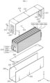
- FIG. 1 is an exploded perspective view showing the configuration of a battery submodule 200 according to an embodiment of the present disclosure.
- FIG. 2 is a view showing a battery submodule 200 according to an embodiment of the present disclosure.
- the battery submodule 200 according to an embodiment of the present disclosure may include a plurality of battery cells 100, 100a, 100b, 100c, 100d, an upper case 210, and a lower case 240.
- the battery submodule 200 may be referred to as a cell bank 200 or a cell assembly 200.
- the battery submodule 200 may be meant to include fewer battery cells 100 than a typical battery module.
- the battery submodule 200 is a unit smaller than a typical battery module, so that two or more battery submodules 200 may be included in one battery module.
- a plurality of battery cells included in one battery module may be grouped by a predetermined number, and each grouped unit may directly become a battery submodule 200.
- the battery submodule 200 may be meant to be smaller in size or have a simpler structure than a typical battery module.
- the battery cell 100 may be provided in plurality.
- a plurality of battery cells 100 may be two to four battery cells 100.
- Each of the plurality of battery cells 100 may have at least one electrode lead 103, 103a, 103b, 103c, 103d protruding toward the front.
- each of the plurality of battery cells 100 may have another electrode lead 103 protruding toward the rear.
- the plurality of battery cells 100 may be stacked in the left-right direction. Alternatively, the plurality battery cells 100 may be stacked in the Y-axis direction.
- the plurality of battery cells 100 may be pouch-type secondary batteries.
- Such a pouch-type secondary battery may be configured in a form where an electrode assembly and an electrolyte are accommodated inside a pouch exterior material.
- the pouch exterior material may be configured to seal the edges of two pouches in a state where the electrode assembly and the electrolyte are accommodated.
- the pouch-type secondary battery may be configured such that a storage portion is located at the center and a sealing portion surrounds the periphery.
- the pouch-type secondary battery may be configured in a rectangular shape with four edges, and three or four of the four edges may be sealed.
- the upper case 210 may include a front plate 212.
- the front plate 212 may cover the front side of the plurality of battery cells 100.
- the upper case 210 may include a top plate 211.
- the top plate 211 may extend rearward from the front plate 212.
- the top plate 211 may be configured to cover the upper side of the plurality of battery cells 100.
- the top plate 211 and the front plate 212 may form a space, and a plurality of battery cells 100 may be accommodated in the space formed by the top plate 211 and the front plate 212.
- the upper case 210 may be made of a metal material.
- the lower case 240 may be coupled to the upper case 210.
- the lower case 240 may form a space, and a plurality of battery cells 100 may be accommodated in the space formed by the lower case 240.
- the upper case 210 and the lower case 240 may accommodate a plurality of battery cells 100 together.
- the lower case 240 may be made of a metal material.
- the upper case 210 and the lower case 240 may form the exterior of the battery submodule 200.
- thermal safety of the battery may be ensured.
- a plurality of battery cells are grouped into battery submodules 200, which can be said to be smaller units compared to conventional battery modules, and these battery submodules 200 may include a relatively small number of battery cells 100. Therefore, by controlling thermal events on a per battery submodule 200 basis, damage by thermal events that may occur from the battery cell 100 may be minimized.
- a thermal event occurs from any one of the battery cells 100, it is possible to suppress propagation of the thermal event to the outside of the battery submodule 200 including the battery cell 100.
- the upper case 210 and lower case 240 of the battery submodule 200 may prevent flame or venting gas generated from the battery cell 100 from leaking out of the battery submodule 200.
- the extent of damage by the thermal event may be limited to the battery submodule 200 including the battery cell 100 in which the thermal event occurred.
- the battery submodule 200 in which no thermal event has occurred may be protected from the thermal event, and the overall thermal stability of the battery pack or product may be improved.
- the battery cell in the case of a battery pack or product adopting the battery submodule 200 of the present disclosure, the battery cell may be managed in a smaller unit than in the case where a typical battery module is adopted. As a result, replacement or maintenance of the battery cell may be facilitated.
- the parts that constitute the exterior of the battery submodule 200 are composed of the upper case 210 and the lower case 240, so the number of parts of the battery submodule 200 may be less than the number of parts of a typical battery module. For this reason, the structure of the battery submodule 200 may be simplified, and the assemblability or productivity of the battery submodule 200 may be improved.
- the front plate 212 and top plate 211 of the battery submodule 200 may be integrally formed.
- the front plate 212 and the top plate 211 may be formed by bending one plate.
- the structure or manufacturing process of the upper case 210 may be simplified. As a result, the assemblability or productivity of the battery submodule 200 may be improved. Also, the weight of the battery submodule 200 may be reduced. In addition, according to this embodiment, there is no gap between the front plate 212 and the top plate 211, and thus leakage of flame or gas through the gap may be prevented.
- the upper case 210 of the battery submodule 200 may further include a rear plate 213, as shown in FIG. 1 .
- the rear plate 213 may extend from the top plate 211.
- the rear plate 213 may cover the rear side of the plurality of battery cells 100.
- the rear plate 213 may extend downward from the rear end of the top plate 211 and face the front plate 212.
- the rear plate 213 may be made of a metal material.
- a plurality of battery cells 100 may be accommodated in the space formed by the front plate 212, top plate 211, and rear plate 213.
- the plurality of battery cells may not be exposed to the outside due to the upper cover, and thermal events that may occur from the plurality of battery cells may be prevented from being propagated to the outside.
- the front plate 212, top plate 211, and rear plate 213 of the battery submodule 200 may be integrally formed.
- the front plate 212, top plate 211, and rear plate 213 may be formed by bending one plate.
- the structure or manufacturing process of the upper case 210 may be simplified. As a result, the assembability or productivity of the battery submodule 200 may be improved. Also, the weight of the battery submodule 200 may be reduced. In addition, according to this embodiment, there is no gap between the rear plate 213 and the top plate 211, and thus leakage of flame or gas through the gap may be prevented.
- FIG. 3 is a view showing a plurality of battery cells 100 according to an embodiment of the present disclosure.
- the battery submodule 200 may further include an adhesive member 120.
- the adhesive member 120 may be disposed between neighboring battery cells 100 among the plurality of battery cells 100.
- the adhesive member 120 may be a double-sided tape.
- a plurality of battery cells 100 may be fixed to each other by the adhesive member 120.
- the plurality of battery cells 100 are fixed to each other, so that the alignment of the plurality of battery cells 100 may be stably maintained and the coupling with other components may be improved.
- the battery submodule 200 may further include a pad 110, as shown in FIG. 3 .
- the pad 110 may be attached to the side surface 105a of the outermost battery cells 100a, 100d among the plurality of battery cells 100.
- An adhesive member 120 may be disposed between the pad 110 and the side surface of the battery cell 100a.
- the pad 110 may have electrical insulating properties.
- the pad 100 may include a silicone material.
- the pad 110 may electrically insulate the plurality of battery cells 100 from other adjacent components and improve the electrical stability of the battery submodule 200.
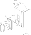
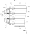
- FIG. 4 is a view showing the coupling of a bus bar 230, a gasket 220, and an upper case 210 according to an embodiment of the present disclosure.
- FIG. 5 is a view showing a portion of the cross-sectional configuration taken along the cutting line A-A' in FIG. 1 .
- FIG. 6 is a view showing a bus bar 230 and a battery cell 100 according to an embodiment of the present disclosure.
- the upper case 210 of the battery submodule 200 may further include a hole 212a formed in the front plate 212.
- the hole 212a may be formed in a rectangular shape.
- the hole 212a may penetrate the front plate 212.
- the upper case 210 may further include a bus bar 230.
- the bus bar 230 may be located in the hole 212a and may be electrically connected to the electrode leads 103 of the plurality of battery cells 100.
- the bus bar 230 may have a bar shape or a block shape.
- the bus bar 230 may be referred to as a block 230, a bus bar block 230, or a bus block 230.
- the bus bar 230 may collect the output of a plurality of battery cells 100, and the output of the battery submodule 200 may be configured differently depending on the number of battery cells 100.
- the bus bar 230 may be easily mounted on the upper case 210, and the coupling state of the bus bar 230 may be stably maintained after mounting.
- the upper case 210 of the battery submodule 200 may further include a gasket 220.
- the gasket 220 may be located between the hole 212a and the bus bar 230.
- the gasket 220 may electrically insulate the bus bar 230 and the front plate 212.
- the gasket 220 may include a silicon material.
- the gasket 220 may prevent contact between the bus bar 230 and the front plate 212 and prevent power output from the plurality of battery cells 100 from leaking. Accordingly, the electrical stability of the battery submodule 200 may be improved.
- the gasket 220 of the battery submodule 200 may extend along the circumference of the bus bar 230.
- the gasket 220 may have a rectangular shape in which the hole 224 is formed. The gasket 220 may seal between the hole 224 and the bus bar 230.
- the front plate 212 may be coupled to the gasket 220 and the bus bar 230.
- the gasket 220 may be assembled, fitted, fixed, bonded, or coupled to the hole 212a of the front plate 212.
- the bus bar 230 may be assembled, fitted, fixed, bonded, or coupled to the hole 224 of the gasket 220.
- the gasket 220 may include a first part 221 that is in contact with, fixed to, or coupled to a front surface of the front plate 212.
- the first part 221 may cover the front surface of the front plate 212.
- the gasket 220 may include a second part 222 that is in contact with, fixed to, or coupled to a rear surface of the front plate 212.
- the second part 222 may cover the rear surface of the front plate 212.
- the gasket 220 may include a third part 223 connecting the first part 221 and the second part 222.
- the third part 223 may be in contact with the front plate 212 and the bus bar 230.
- the hole in the front plate may be sealed by the gasket 220 and the bus bar. Therefore, the inflow and outflow of materials into and out of the battery submodule may be blocked. Moreover, as a result, even if a thermal event occurs inside the battery submodule, propagation thereof to the outside may be blocked.
- the assemblability or productivity of the battery submodule 200 may be improved by inserting the bus bar 230 into the hole 224 and coupling it to the gasket 220.
- the assembability or productivity of the battery submodule 200 may be improved by inserting the gasket 220 into the hole 212a and coupling it to the front plate 212. Also, in this case, the coupling force and sealing force between the gasket 220 and the front plate 212 may be stably secured.
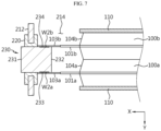
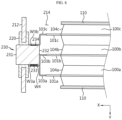
- FIGS. 7 to 9 are views schematically showing a partial configuration of a battery submodule according to various embodiments of the present disclosure.
- FIGS. 7 to 9 are views showing various embodiments of the coupling portion of the bus bar 230 and the battery cell 100 in the cross-sectional configuration taken along the cutting line B-B' in FIG. 6 .
- the bus bar 230 of the battery submodule 200 may further include side surfaces 233, 234 extending toward the plurality of battery cells 100.
- the bus bar 230 may include a front surface 231, a rear surface 232 facing the front surface 231, and side surfaces 233, 234 connecting the front surface 231 and the rear surface 232.
- the side surfaces 233, 234 may have a right surface 233 and a left surface 234.
- the electrode leads 103 of the plurality of battery cells 100 may be connected to the side surfaces 233, 234 of the bus bar 230.
- the electrode lead 103 and the bus bar 230 may be connected through laser welding and form a welding portion W1.
- the laser for welding may be irradiated in the +Y-axis or -Y-axis direction.
- two battery cells 100a, 100b may be connected to one bus bar 230.
- the electrode lead 103a of the first battery cell 100a may be connected in contact with the right surface 233 of the bus bar 230, and a welding portion W2a may be formed.
- the electrode lead 103b of the second battery cell 100b may be connected in contact with the left surface 234 of the bus bar 230, and a welding portion W2b may be formed.
- three battery cells 100a, 100b, 100c may be connected to one bus bar 230.
- the electrode lead 103b of the second battery cell 100b may be connected in contact with the right surface 233 of the bus bar 230, and a welding portion W3a may be formed.
- the electrode lead 103a of the first battery cell 100a may be connected in contact with the electrode lead 103b of the second battery cell 100b, and a welding portion W4a may be formed. That is, two or more electrode leads may be stacked on one surface of the bus bar 230 and then welded together with the bus bar 230.
- the electrode lead 103c of the third battery cell 100c may be connected in contact with the left surface 234 of the bus bar 230, and a welding portion W3b may be formed.
- four battery cells 100a, 100b, 100c, 100d may be connected to one bus bar 230.
- the electrode lead 103b of the second battery cell 100b may be connected to the right surface 233 of the bus bar 230, and a welding portion W6a may be formed.
- the electrode lead 103a of the first battery cell 100a may be connected to the electrode lead 103b of the second battery cell 100b, and a welding portion W5a may be formed.
- the electrode lead 103c of the third battery cell 100c may be connected to the left surface 234 of the bus bar 230, and a welding portion W5b may be formed.
- the electrode lead 103d of the fourth battery cell 100d may be connected to the electrode lead 103c of the third battery cell 100c, and a welding portion W6a may be formed.
- a welding portion W6a may be formed.
- the space 214 provided by the upper case 210 may be open in the Y-axis direction, and a laser for welding may be irradiated in the Y-axis direction.
- a laser irradiated in the -Y-axis direction may weld the electrode lead 103 of the battery cell 100 to the right surface 233 of the bus bar 230.
- a laser irradiated in the +Y-axis direction may weld the electrode lead 103 of the battery cell 100 to the left surface 234 of the bus bar 230.
- the assemblability or productivity of the battery submodule 200 may be improved.
- FIG. 10 is a view showing the coupling of an upper case 210 and a lower case 240 according to an embodiment of the present disclosure.
- the lower case 240 may form an empty space 244 therein together with the upper case 210.
- the lower case 240 may include a bottom plate 241, a left plate 243, and a right plate 242.
- the left plate 243 and the right plate 242 may extend upward from the bottom plate 241.
- the left plate 243 and the right plate 242 may be parallel to, opposite to, or facing each other.
- the left plate 243, the right plate 242, and the bottom plate 241 may be integrally formed.
- a plurality of battery cells 100 may be accommodated in the space 244 formed by the lower case 240.
- the space 214 provided by the upper case 210 and the space 244 provided by the lower case 240 may overlap.
- the lower case 240 and the upper case 210 may be configured to cover the entire portion of the cell assembly in a coupled state.
- the lower case 240 and the upper case 210 may be configured to cover different side surfaces of the cell assembly.
- the lower case 240 may be configured in a U-shaped frame to cover the bottom, left, and right sides of the battery cell 100.
- the upper case 210 may be configured in a n-shaped frame to cover the top, front, and rear sides of the battery cell 100. That is, the plurality of battery cells 100 may be accommodated in an interior space limited and enclosed by the combination of the upper case 210 and the lower case 240.
- the interior space of the battery submodule 200 may be completely blocked from the outside. Therefore, even if thermal events occur from a plurality of battery cells 100, propagation of such thermal events to the outside of the battery submodule 200 may be blocked.
- an adhesive member 250 may be disposed or applied to the upper surface of the bottom plate 241.
- the adhesive member 250 may fix the battery cell 100 to the lower case 240.
- the adhesive member 250 may transfer heat generated from the battery cell 100 to the lower case 240.
- the adhesive member 250 may be a thermal adhesive resin or thermal resin with adhesive or thermal conductivity.
- the stability of the battery submodule 200 may be improved by fixing a plurality of battery cells 100 to the lower case 240.
- FIG. 11 is a view showing a configuration of the upper case 210 and the lower case 240.
- the upper case 210 and the lower case 240 may further include a plurality of metal materials.
- the upper case 210 and/or the lower case 240 may be configured in a multi-layer structure.
- the upper case 210 or the lower case 240 may be made of a clad metal 201 material.
- the clad metal 201 may include three layers.
- the clad metal 201 may be stacked in the order of a first layer 202, a second layer 203, and a third layer 204.
- the upper case 210 or the lower case 240 may be configured such that the third layer 204 is located on the inner side and the first layer 202 is located on the outer side.
- the upper case 210 or the lower case 240 may be manufactured by processing the clad metal 201.
- the upper case 210 or the lower case 240 may be manufactured by bending or cutting the clad metal 201.
- the first layer 202 may be a metal material that is easily welded.
- the first layer 202 may be an aluminum material.
- the first layer 202 may be formed to have a thickness of 1.5t to 1.8t.
- the second layer 203 may be a metal material with high durability against heat.
- the second layer 203 may be a metal material having properties favorable for blocking heat or flame.
- the second layer 203 may be stainless steel (SUS).
- the second layer 203 may be formed to have a thickness of 0.2t to 0.5t.
- the second layer 203 may be bonded on the first layer 202.
- the third layer 204 may be an electrically insulating material.
- the third layer 204 may be a polyethylene terephthalate (PET) film.
- PET polyethylene terephthalate
- the structure or manufacturing process of the upper case 210 or the lower case 240 may be simplified. As a result, the assemblability or productivity of the battery submodule 200 may be improved.
- the upper case 210 or the lower case 240 includes an aluminum material, so that the weight of the battery submodule 200 may be reduced.
- the upper case 210 or the lower case 240 includes an aluminum material, so that the upper case 210 or the lower case 240 may be easily welded, and the assemblability and productivity of the battery submodule 200 may be improved.
- the upper case 210 or the lower case 240 includes a stainless steel material, so that even if thermal events occur from the plurality of battery cells 100, propagation of such thermal events to the outside of the battery submodule 200 may be prevented.
- the upper case 210 or the lower case 240 includes an insulating material, so that the electrical stability of the battery submodule 200 may be improved.
- FIG. 12 is a view showing the coupling of the upper case 210 and the lower case 240 according to an embodiment of the present disclosure.
- the upper case 210 and lower case 240 of the battery submodule 200 according to an embodiment of the present disclosure may be coupled.
- the upper case 210 and the lower case 240 may be made of clad metal 201, and the outer surface of the upper case 210 and the outer surface of the lower case 240 may be the first layer 202.
- the first layer 202 may include an aluminum material.
- the upper case 210 and the lower case 240 may be coupled through laser welding.
- the welding portions W10, W20, W30, W40, W50, W60 may be formed along the circumference of the front plate 212, top plate 211, and rear plate 213 of the upper case 210.
- the welding portions W10, W20, W30, W40, W50, W60 may be formed along the circumference of the bottom plate 241, left plate 243, and right plate 244 of the lower case 240.
- the upper case 210 and the lower case 240 may be easily assembled, and coupling properties may be improved.
- the interior of the battery submodule 200 may be sealed by performing a welding process along the circumference of the upper case 210 or the lower case 240, and even if thermal events occur from a plurality of battery cells 100, propagation thereof to the outside of the battery submodule 200 may be blocked.
- the upper case 210 of the battery submodule 200 may further include a step portion 215.
- the lower case 240 may be in contact with, arranged, or aligned with the step portion 215 of the upper case 210.
- the welding process of the upper case 210 and the lower case 240 may be performed quickly and accurately, and the assemblability or productivity of the battery submodule 200 may be improved.
- FIG. 13 is a view showing that a plurality of battery submodules are provided and interconnected according to an embodiment of the present disclosure.
- the battery submodule 200 may be connected in plurality.
- the plurality of battery submodules 200 may be arranged, aligned, or stacked along the horizontal direction (Y-axis direction) and/or the vertical direction (Z-axis direction).
- the terminal bus bar 320 may electrically connect neighboring battery submodules 200.
- the terminal bus bar 320 may be electrically connected to the bus bar 230 of each battery submodule 200.
- the bus bar 230 may collect the output of a plurality of battery submodules 200, and the output of the plurality of battery submodules 200 may be configured differently depending on the number of the plurality of battery submodules 200.
- the battery submodule 200 may be electrically connected to external electronic components.
- the electronic component may be a sensor, a BMS, or a control unit.
- the sensor may obtain status information such as voltage or temperature of one or more battery submodules 200.
- a sensor for obtaining status information of the battery submodule 200 is provided outside the battery submodule 200, so that the size or weight of the battery submodule 200 may be reduced, and the structure of the battery submodule 200 may be simplified.
- FIG. 14 is an exploded perspective view schematically showing the configuration of a battery module according to an embodiment of the present disclosure.
- a battery module 400 may include two or more battery submodules 200 according to the present disclosure described above.
- one battery module 400 may include two battery submodules 200.
- the bus bars of the two battery submodules 200 may be electrically connected to each other by the terminal bus bar 320, as described in the embodiment of FIG. 13 .
- a plurality of battery cells may be included inside one battery module, but the plurality of battery cells may be divided into smaller units and located inside different battery submodules. Therefore, events such as thermal runaway occurring in a specific battery cell may be suppressed from being propagated to other battery submodules, thereby effectively preventing propagation of thermal runaway to the entire battery module.
- the battery module 400 according to the present disclosure may further include various other components in addition to the battery submodule 200, for example, components of a battery module known at the time of filing of the present disclosure, such as a bus bar assembly, a module case 410, a cooling unit, and the like.
- components of a battery module known at the time of filing of the present disclosure such as a bus bar assembly, a module case 410, a cooling unit, and the like.
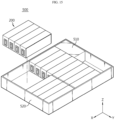
- FIG. 15 is a perspective view schematically showing the configuration of a battery pack according to an embodiment of the present disclosure.
- a battery pack 500 according to the present disclosure may include two or more battery submodules 200 according to the present disclosure described above.
- the battery pack 500 may further include various other components in addition to the battery submodule 200, for example, components of a battery pack known at the time of filing of the present disclosure, such as a BMS 510, a bus bar, a pack case 520, a relay, a current sensor, and the like.
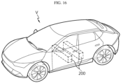
- FIG. 16 is a perspective view schematically showing the configuration of a vehicle according to an embodiment of the present disclosure.
- a vehicle V according to the present disclosure may include two or more battery submodules 200 according to the present disclosure described above.
- the battery submodule 200 according to the present disclosure may be applied to a vehicle such as an electric vehicle or a hybrid vehicle. That is, the vehicle V according to the present disclosure may include a battery submodule 200 according to the present disclosure, a battery module 400 according to the present disclosure, or a battery pack 500 according to the present disclosure.
- the vehicle V according to the present disclosure may further include various other components included in the vehicle V in addition to the battery submodule 200, the battery module 400, or the battery pack 500.
- the vehicle V according to the present disclosure may further include a vehicle body, a motor, a control device such as an electronic control unit (ECU), and the like in addition to the battery submodule 200 according to the present disclosure.
- ECU electronicee control unit
Landscapes
- Chemical & Material Sciences (AREA)
- Chemical Kinetics & Catalysis (AREA)
- Electrochemistry (AREA)
- General Chemical & Material Sciences (AREA)
- Inorganic Chemistry (AREA)
- Engineering & Computer Science (AREA)
- Aviation & Aerospace Engineering (AREA)
- Manufacturing & Machinery (AREA)
- Battery Mounting, Suspending (AREA)
- Connection Of Batteries Or Terminals (AREA)
- Secondary Cells (AREA)
Abstract
Description
- The present disclosure relates to a battery submodule.
- The present application claims priority to
Korean Patent Application No. 10-2022-0161981 filed on November 28, 2022 - As the demand for portable electronic products such as laptops, video cameras, and mobile phones has rapidly increased in recent years and the commercialization of robots, electric vehicles, and the like has begun in earnest, research on high-performance secondary batteries capable of repeated charge/discharge has been actively conducted.
- Currently commercialized secondary batteries include nickel cadmium batteries, nickel hydride batteries, nickel zinc batteries, lithium secondary batteries, and the like. In particular, lithium secondary batteries are in the spotlight because they have almost no memory effect compared to nickel-based secondary batteries and thus have advantages of free charge/discharge, very low self-discharge rate, and high energy density.
- Such lithium secondary batteries mainly use a lithium-based oxide and a carbon material as a positive electrode active material and a negative electrode active material, respectively. Lithium secondary batteries include an electrode assembly in which a positive electrode plate and a negative electrode plate coated with the positive electrode active material and the negative electrode active material, respectively, are disposed with a separator therebetween, and an exterior material that seals and accommodates the electrode assembly together with an electrolyte, that is, a battery case.
- In general, lithium secondary batteries may be classified into can-type secondary batteries in which electrode assemblies are embedded in a metal can and pouch-type secondary batteries in which electrode assemblies are embedded in a pouch of aluminum laminate sheets, depending on the shape of an exterior material.
- Recently, secondary batteries have been widely used for driving or energy storage not only in small devices such as portable electronic devices, but also in medium/large devices such as electric vehicles and energy storage systems (ESSs). These secondary batteries are accommodated together inside a module case in a state where a plurality of them are electrically connected, which may form one battery module. In addition, such a battery module may be connected in plurality to form one battery pack.
- However, when a plurality of secondary batteries (battery cells) or a plurality of battery modules are concentrated in a narrow space as described above, they may be vulnerable to thermal events. In particular, when an event such as thermal runaway occurs in any one of the battery cells, high temperature gas, flame, heat, or the like may be generated. If such gas, flame, heat, or the like is transferred to other battery cells included in the same battery module, an explosive chain reaction situation such as thermal propagation may occur. In addition, this chain reaction may cause not only an accident such as fire or explosion in the corresponding battery module, but also fire or explosion in other battery modules.
- Moreover, in the case of medium/large-sized devices such as electric vehicles, a large number of battery cells and battery modules may be included to increase output and/or capacity, thereby further increasing the risk of thermal chain reaction. In addition, in the case of a battery pack mounted on an electric vehicle, there may be a user such as a driver in the vicinity thereof. Therefore, if a thermal event occurring in a specific battery module is not properly controlled and a chain reaction occurs, it may cause not only significant property damage but also loss of life.
- The present disclosure is designed to solve the above-described problems and other problems.
- Still another object of the present disclosure may be to provide a battery submodule capable of suppressing heat propagation.
- Still another object of the present disclosure may be to provide a battery submodule with a reduced size or weight.
- Still another object of the present disclosure may be to provide a battery submodule with a simplified structure.
- Still another object of the present disclosure may be to provide a battery submodule with improved assemblability or productivity.
- Still another object of the present disclosure may be to provide a battery submodule having a sealed interior.
- A battery submodule according to one aspect of the present disclosure for achieving the above-described object may include a plurality of battery cells each having at least one electrode lead protruding toward the front and stacked in the left-right direction; an upper case including a front plate that covers the front side of the plurality of battery cells and a top plate that extends rearward from the front plate and covers the upper side of the plurality of battery cells; and a lower case coupled to the upper case and accommodating the plurality of battery cells together with the upper case.
- In addition, the front plate and the top plate may be integrally formed.
- In addition, the upper case may further include a rear plate that extends from the top plate and covers the rear side of the plurality of battery cells.
- In addition, the front plate, the top plate, and the rear plate may be integrally formed.
- In addition, at least one of the upper case and the lower case may further include a plurality of metal materials.
- In addition, the battery submodule may further include an adhesive member disposed between neighboring battery cells among the plurality of battery cells.
- In addition, the upper case may further include a hole formed in the front plate; and a bus bar located in the hole and electrically connected to the electrode leads of the plurality of battery cells.
- In addition, the battery submodule may further include a gasket located between the hole and the bus bar and electrically insulating the bus bar and the front plate.
- In addition, the gasket may extend along the circumference of the bus bar and seal between the hole and the bus bar.
- In addition, the bus bar may further include a side surface extending toward the plurality of battery cells, wherein the electrode leads of the plurality of battery cells may be connected to the side surface.
- In addition, the battery submodule may further include a sensor located outside the upper case and electrically connected to the bus bar.
- In addition, a battery module according to another aspect of the present disclosure for achieving the above-described object may include two or more battery submodules according to the present disclosure.
- In addition, a battery pack according to still another aspect of the present disclosure for achieving the above-described object may include two or more battery submodules according to the present disclosure.
- In addition, a vehicle according to still another aspect of the present disclosure for achieving the above-described object may include two or more battery submodules according to the present disclosure.
- According to at least one of the embodiments of the present disclosure, a battery submodule capable of suppressing heat propagation may be provided.
- According to at least one of the embodiments of the present disclosure, a battery submodule with a reduced size or weight may be provided.
- According to at least one of the embodiments of the present disclosure, a battery submodule with a simplified structure may be provided.
- According to at least one of the embodiments of the present disclosure, a battery submodule with improved assemblability or productivity may be provided.
- According to at least one of the embodiments of the present disclosure, a battery submodule having a sealed interior may be provided.
- In addition, the present disclosure may have various other effects, which will be described in each embodiment, or descriptions of effects that may be easily understood by those skilled in the art will be omitted.
- The accompanying drawings illustrate a preferred embodiment of the present disclosure and together with the foregoing disclosure, serve to provide further understanding of the technical features of the present disclosure, and thus the present disclosure is not construed as being limited to the drawing.
-
FIG. 1 is an exploded perspective view showing the configuration of a battery submodule according to an embodiment of the present disclosure. -
FIG. 2 is a view showing a battery submodule according to an embodiment of the present disclosure. -
FIG. 3 is a view showing a plurality of battery cells according to an embodiment of the present disclosure. -
FIG. 4 is a view showing the coupling of a bus bar, a gasket, and an upper case according to an embodiment of the present disclosure. -
FIG. 5 is a view showing a portion of the cross-sectional configuration taken along the cutting line A-A' inFIG. 1 . -
FIG. 6 is a view showing the coupling of a bus bar and a battery cell according to an embodiment of the present disclosure. -
FIGS. 7 to 9 are views showing the coupling portion of a bus bar and a battery cell in the cross-sectional configuration taken along the cutting line B-B' inFIG. 6 . -
FIGS. 10 to 12 are views showing the coupling of an upper case and a lower case according to an embodiment of the present disclosure. -
FIG. 13 is a view showing that a plurality of battery submodules are provided and interconnected according to an embodiment of the present disclosure. -
FIG. 14 is a view showing a battery module including a plurality of battery submodules according to an embodiment of the present disclosure. -
FIG. 15 is a view showing a battery pack including a plurality of battery submodules according to an embodiment of the present disclosure. -
FIG. 16 is a view showing a vehicle including a plurality of battery submodules according to an embodiment of the present disclosure. - Hereinafter, preferred embodiments of the present disclosure will be described in detail with reference to the accompanying drawings. Prior to the description, it should be understood that the terms used in the specification and the appended claims should not be construed as limited to general and dictionary meanings, but interpreted based on the meanings and concepts corresponding to technical aspects of the present disclosure on the basis of the principle that the inventor is allowed to define terms appropriately for the best explanation.
- Therefore, the description proposed herein is just a preferable example for the purpose of illustrations only, not intended to limit the scope of the disclosure, so it should be understood that other equivalents and modifications could be made thereto without departing from the scope of the disclosure.
-
FIG. 1 is an exploded perspective view showing the configuration of abattery submodule 200 according to an embodiment of the present disclosure.FIG. 2 is a view showing abattery submodule 200 according to an embodiment of the present disclosure. Referring toFIGS. 1 and2 , thebattery submodule 200 according to an embodiment of the present disclosure may include a plurality ofbattery cells upper case 210, and alower case 240. - The battery submodule 200 may be referred to as a
cell bank 200 or acell assembly 200. The battery submodule 200 may be meant to includefewer battery cells 100 than a typical battery module. In particular, thebattery submodule 200 is a unit smaller than a typical battery module, so that two ormore battery submodules 200 may be included in one battery module. For example, a plurality of battery cells included in one battery module may be grouped by a predetermined number, and each grouped unit may directly become abattery submodule 200. Alternatively, thebattery submodule 200 may be meant to be smaller in size or have a simpler structure than a typical battery module. - The
battery cell 100 may be provided in plurality. For example, a plurality ofbattery cells 100 may be two to fourbattery cells 100. Each of the plurality ofbattery cells 100 may have at least oneelectrode lead battery cells 100 may have anotherelectrode lead 103 protruding toward the rear. - The plurality of
battery cells 100 may be stacked in the left-right direction. Alternatively, theplurality battery cells 100 may be stacked in the Y-axis direction. The plurality ofbattery cells 100 may be pouch-type secondary batteries. Such a pouch-type secondary battery may be configured in a form where an electrode assembly and an electrolyte are accommodated inside a pouch exterior material. The pouch exterior material may be configured to seal the edges of two pouches in a state where the electrode assembly and the electrolyte are accommodated. The pouch-type secondary battery may be configured such that a storage portion is located at the center and a sealing portion surrounds the periphery. The pouch-type secondary battery may be configured in a rectangular shape with four edges, and three or four of the four edges may be sealed. - The
upper case 210 may include afront plate 212. Thefront plate 212 may cover the front side of the plurality ofbattery cells 100. Theupper case 210 may include atop plate 211. Thetop plate 211 may extend rearward from thefront plate 212. Thetop plate 211 may be configured to cover the upper side of the plurality ofbattery cells 100. Thetop plate 211 and thefront plate 212 may form a space, and a plurality ofbattery cells 100 may be accommodated in the space formed by thetop plate 211 and thefront plate 212. Theupper case 210 may be made of a metal material. - The
lower case 240 may be coupled to theupper case 210. Thelower case 240 may form a space, and a plurality ofbattery cells 100 may be accommodated in the space formed by thelower case 240. Theupper case 210 and thelower case 240 may accommodate a plurality ofbattery cells 100 together. Thelower case 240 may be made of a metal material. Theupper case 210 and thelower case 240 may form the exterior of thebattery submodule 200. - According to this configuration of the present disclosure, thermal safety of the battery may be ensured. In particular, according to one aspect of the present disclosure, a plurality of battery cells are grouped into
battery submodules 200, which can be said to be smaller units compared to conventional battery modules, and thesebattery submodules 200 may include a relatively small number ofbattery cells 100. Therefore, by controlling thermal events on a perbattery submodule 200 basis, damage by thermal events that may occur from thebattery cell 100 may be minimized. For example, in the case of a battery module, a battery pack, or a battery-equipped product including a plurality ofbattery submodules 200 of the present disclosure, even if a thermal event occurs from any one of thebattery cells 100, it is possible to suppress propagation of the thermal event to the outside of thebattery submodule 200 including thebattery cell 100. - Moreover, the
upper case 210 andlower case 240 of thebattery submodule 200 may prevent flame or venting gas generated from thebattery cell 100 from leaking out of thebattery submodule 200. As a result, the extent of damage by the thermal event may be limited to thebattery submodule 200 including thebattery cell 100 in which the thermal event occurred. The battery submodule 200 in which no thermal event has occurred may be protected from the thermal event, and the overall thermal stability of the battery pack or product may be improved. - In addition, according to this configuration of the present disclosure, in the case of a battery pack or product adopting the
battery submodule 200 of the present disclosure, the battery cell may be managed in a smaller unit than in the case where a typical battery module is adopted. As a result, replacement or maintenance of the battery cell may be facilitated. - In addition, according to this configuration of the present disclosure, the parts that constitute the exterior of the
battery submodule 200 are composed of theupper case 210 and thelower case 240, so the number of parts of thebattery submodule 200 may be less than the number of parts of a typical battery module. For this reason, the structure of thebattery submodule 200 may be simplified, and the assemblability or productivity of thebattery submodule 200 may be improved. - The
front plate 212 andtop plate 211 of thebattery submodule 200 according to an embodiment of the present disclosure may be integrally formed. For example, thefront plate 212 and thetop plate 211 may be formed by bending one plate. - According to this configuration of the present disclosure, the structure or manufacturing process of the
upper case 210 may be simplified. As a result, the assemblability or productivity of thebattery submodule 200 may be improved. Also, the weight of thebattery submodule 200 may be reduced. In addition, according to this embodiment, there is no gap between thefront plate 212 and thetop plate 211, and thus leakage of flame or gas through the gap may be prevented. - The
upper case 210 of thebattery submodule 200 according to an embodiment of the present disclosure may further include arear plate 213, as shown inFIG. 1 . Therear plate 213 may extend from thetop plate 211. Therear plate 213 may cover the rear side of the plurality ofbattery cells 100. Therear plate 213 may extend downward from the rear end of thetop plate 211 and face thefront plate 212. Therear plate 213 may be made of a metal material. - According to this configuration of the present disclosure, a plurality of
battery cells 100 may be accommodated in the space formed by thefront plate 212,top plate 211, andrear plate 213. - According to this configuration of the present disclosure, the plurality of battery cells may not be exposed to the outside due to the upper cover, and thermal events that may occur from the plurality of battery cells may be prevented from being propagated to the outside.
- The
front plate 212,top plate 211, andrear plate 213 of thebattery submodule 200 according to an embodiment of the present disclosure may be integrally formed. For example, thefront plate 212,top plate 211, andrear plate 213 may be formed by bending one plate. - According to this configuration of the present disclosure, the structure or manufacturing process of the
upper case 210 may be simplified. As a result, the assembability or productivity of thebattery submodule 200 may be improved. Also, the weight of thebattery submodule 200 may be reduced. In addition, according to this embodiment, there is no gap between therear plate 213 and thetop plate 211, and thus leakage of flame or gas through the gap may be prevented. -
FIG. 3 is a view showing a plurality ofbattery cells 100 according to an embodiment of the present disclosure. - Referring to
FIG. 3 , thebattery submodule 200 according to an embodiment of the present disclosure may further include anadhesive member 120. Theadhesive member 120 may be disposed between neighboringbattery cells 100 among the plurality ofbattery cells 100. For example, theadhesive member 120 may be a double-sided tape. A plurality ofbattery cells 100 may be fixed to each other by theadhesive member 120. - According to this configuration of the present disclosure, the plurality of
battery cells 100 are fixed to each other, so that the alignment of the plurality ofbattery cells 100 may be stably maintained and the coupling with other components may be improved. - The battery submodule 200 according to an embodiment of the present disclosure may further include a
pad 110, as shown inFIG. 3 . Thepad 110 may be attached to theside surface 105a of theoutermost battery cells battery cells 100. Anadhesive member 120 may be disposed between thepad 110 and the side surface of thebattery cell 100a. Thepad 110 may have electrical insulating properties. For example, thepad 100 may include a silicone material. - According to this configuration of the present disclosure, the
pad 110 may electrically insulate the plurality ofbattery cells 100 from other adjacent components and improve the electrical stability of thebattery submodule 200. -
FIG. 4 is a view showing the coupling of abus bar 230, agasket 220, and anupper case 210 according to an embodiment of the present disclosure.FIG. 5 is a view showing a portion of the cross-sectional configuration taken along the cutting line A-A' inFIG. 1 .FIG. 6 is a view showing abus bar 230 and abattery cell 100 according to an embodiment of the present disclosure. - Referring to
FIGS. 4 to 6 , theupper case 210 of thebattery submodule 200 according to an embodiment of the present disclosure may further include ahole 212a formed in thefront plate 212. Thehole 212a may be formed in a rectangular shape. Thehole 212a may penetrate thefront plate 212. - In addition, the
upper case 210 may further include abus bar 230. Thebus bar 230 may be located in thehole 212a and may be electrically connected to the electrode leads 103 of the plurality ofbattery cells 100. Thebus bar 230 may have a bar shape or a block shape. Thebus bar 230 may be referred to as ablock 230, abus bar block 230, or abus block 230. - According to this configuration of the present disclosure, the
bus bar 230 may collect the output of a plurality ofbattery cells 100, and the output of thebattery submodule 200 may be configured differently depending on the number ofbattery cells 100. In addition, according to this embodiment, thebus bar 230 may be easily mounted on theupper case 210, and the coupling state of thebus bar 230 may be stably maintained after mounting. - The
upper case 210 of thebattery submodule 200 according to an embodiment of the present disclosure may further include agasket 220. Thegasket 220 may be located between thehole 212a and thebus bar 230. Thegasket 220 may electrically insulate thebus bar 230 and thefront plate 212. For example, thegasket 220 may include a silicon material. - According to this configuration of the present disclosure, the
gasket 220 may prevent contact between thebus bar 230 and thefront plate 212 and prevent power output from the plurality ofbattery cells 100 from leaking. Accordingly, the electrical stability of thebattery submodule 200 may be improved. - Referring to
FIG. 4 , thegasket 220 of thebattery submodule 200 according to an embodiment of the present disclosure may extend along the circumference of thebus bar 230. For example, if thebus bar 230 has a rectangular rod shape and thehole 212a of thefront plate 212 has a rectangular shape, thegasket 220 may have a rectangular shape in which thehole 224 is formed. Thegasket 220 may seal between thehole 224 and thebus bar 230. - The
front plate 212 may be coupled to thegasket 220 and thebus bar 230. Thegasket 220 may be assembled, fitted, fixed, bonded, or coupled to thehole 212a of thefront plate 212. Thebus bar 230 may be assembled, fitted, fixed, bonded, or coupled to thehole 224 of thegasket 220. - Referring to
FIG. 5 , thegasket 220 may include afirst part 221 that is in contact with, fixed to, or coupled to a front surface of thefront plate 212. Thefirst part 221 may cover the front surface of thefront plate 212. Thegasket 220 may include asecond part 222 that is in contact with, fixed to, or coupled to a rear surface of thefront plate 212. Thesecond part 222 may cover the rear surface of thefront plate 212. Thegasket 220 may include athird part 223 connecting thefirst part 221 and thesecond part 222. Thethird part 223 may be in contact with thefront plate 212 and thebus bar 230. - According to this configuration of the present disclosure, the hole in the front plate may be sealed by the
gasket 220 and the bus bar. Therefore, the inflow and outflow of materials into and out of the battery submodule may be blocked. Moreover, as a result, even if a thermal event occurs inside the battery submodule, propagation thereof to the outside may be blocked. - In addition, according to this configuration of the present disclosure, the assemblability or productivity of the
battery submodule 200 may be improved by inserting thebus bar 230 into thehole 224 and coupling it to thegasket 220. - In addition, according to this configuration of the present disclosure, the assembability or productivity of the
battery submodule 200 may be improved by inserting thegasket 220 into thehole 212a and coupling it to thefront plate 212. Also, in this case, the coupling force and sealing force between thegasket 220 and thefront plate 212 may be stably secured. -
FIGS. 7 to 9 are views schematically showing a partial configuration of a battery submodule according to various embodiments of the present disclosure. For example,FIGS. 7 to 9 are views showing various embodiments of the coupling portion of thebus bar 230 and thebattery cell 100 in the cross-sectional configuration taken along the cutting line B-B' inFIG. 6 . - Referring to
FIGS. 6 to 9 , thebus bar 230 of thebattery submodule 200 according to an embodiment of the present disclosure may further include side surfaces 233, 234 extending toward the plurality ofbattery cells 100. Thebus bar 230 may include afront surface 231, arear surface 232 facing thefront surface 231, andside surfaces front surface 231 and therear surface 232. The side surfaces 233, 234 may have aright surface 233 and aleft surface 234. - The electrode leads 103 of the plurality of
battery cells 100 may be connected to the side surfaces 233, 234 of thebus bar 230. For example, theelectrode lead 103 and thebus bar 230 may be connected through laser welding and form a welding portion W1. The laser for welding may be irradiated in the +Y-axis or -Y-axis direction. - Referring to
FIG. 7 , twobattery cells bus bar 230. In this case, theelectrode lead 103a of thefirst battery cell 100a may be connected in contact with theright surface 233 of thebus bar 230, and a welding portion W2a may be formed. Theelectrode lead 103b of thesecond battery cell 100b may be connected in contact with theleft surface 234 of thebus bar 230, and a welding portion W2b may be formed. - Referring to
FIG. 8 , threebattery cells bus bar 230. In this case, theelectrode lead 103b of thesecond battery cell 100b may be connected in contact with theright surface 233 of thebus bar 230, and a welding portion W3a may be formed. Theelectrode lead 103a of thefirst battery cell 100a may be connected in contact with theelectrode lead 103b of thesecond battery cell 100b, and a welding portion W4a may be formed. That is, two or more electrode leads may be stacked on one surface of thebus bar 230 and then welded together with thebus bar 230. In addition, theelectrode lead 103c of thethird battery cell 100c may be connected in contact with theleft surface 234 of thebus bar 230, and a welding portion W3b may be formed. - Referring to
FIG. 9 , fourbattery cells bus bar 230. In this case, theelectrode lead 103b of thesecond battery cell 100b may be connected to theright surface 233 of thebus bar 230, and a welding portion W6a may be formed. Theelectrode lead 103a of thefirst battery cell 100a may be connected to theelectrode lead 103b of thesecond battery cell 100b, and a welding portion W5a may be formed. Theelectrode lead 103c of thethird battery cell 100c may be connected to theleft surface 234 of thebus bar 230, and a welding portion W5b may be formed. Theelectrode lead 103d of thefourth battery cell 100d may be connected to theelectrode lead 103c of thethird battery cell 100c, and a welding portion W6a may be formed. In this embodiment, it can be said that two or more electrode leads are stacked on each of both surfaces of thebus bar 230 and then welded to thebus bar 230. - According to this configuration of the present disclosure, weldability between the electrode lead and the
bus bar 230 can be greatly improved. In particular, thespace 214 provided by theupper case 210 may be open in the Y-axis direction, and a laser for welding may be irradiated in the Y-axis direction. For example, a laser irradiated in the -Y-axis direction may weld theelectrode lead 103 of thebattery cell 100 to theright surface 233 of thebus bar 230. In addition, a laser irradiated in the +Y-axis direction may weld theelectrode lead 103 of thebattery cell 100 to theleft surface 234 of thebus bar 230. As a result, the assemblability or productivity of thebattery submodule 200 may be improved. -
FIG. 10 is a view showing the coupling of anupper case 210 and alower case 240 according to an embodiment of the present disclosure. - Referring to
FIG. 10 , thelower case 240 according to an embodiment of the present disclosure may form anempty space 244 therein together with theupper case 210. Thelower case 240 may include abottom plate 241, aleft plate 243, and aright plate 242. Theleft plate 243 and theright plate 242 may extend upward from thebottom plate 241. Theleft plate 243 and theright plate 242 may be parallel to, opposite to, or facing each other. - The
left plate 243, theright plate 242, and thebottom plate 241 may be integrally formed. A plurality ofbattery cells 100 may be accommodated in thespace 244 formed by thelower case 240. Thespace 214 provided by theupper case 210 and thespace 244 provided by thelower case 240 may overlap. - The
lower case 240 and theupper case 210 may be configured to cover the entire portion of the cell assembly in a coupled state. In particular, thelower case 240 and theupper case 210 may be configured to cover different side surfaces of the cell assembly. For example, thelower case 240 may be configured in a U-shaped frame to cover the bottom, left, and right sides of thebattery cell 100. In addition, theupper case 210 may be configured in a n-shaped frame to cover the top, front, and rear sides of thebattery cell 100. That is, the plurality ofbattery cells 100 may be accommodated in an interior space limited and enclosed by the combination of theupper case 210 and thelower case 240. - Moreover, according to this configuration of the present disclosure, the interior space of the
battery submodule 200 may be completely blocked from the outside. Therefore, even if thermal events occur from a plurality ofbattery cells 100, propagation of such thermal events to the outside of thebattery submodule 200 may be blocked. - Meanwhile, as shown in
FIG. 10 , anadhesive member 250 may be disposed or applied to the upper surface of thebottom plate 241. Theadhesive member 250 may fix thebattery cell 100 to thelower case 240. Theadhesive member 250 may transfer heat generated from thebattery cell 100 to thelower case 240. For example, theadhesive member 250 may be a thermal adhesive resin or thermal resin with adhesive or thermal conductivity. - In addition, according to this configuration of the present disclosure, the stability of the
battery submodule 200 may be improved by fixing a plurality ofbattery cells 100 to thelower case 240. -
FIG. 11 is a view showing a configuration of theupper case 210 and thelower case 240. - Referring to
FIG. 11 , at least one of theupper case 210 and thelower case 240 according to an embodiment of the present disclosure may further include a plurality of metal materials. In particular, theupper case 210 and/or thelower case 240 may be configured in a multi-layer structure. For example, theupper case 210 or thelower case 240 may be made of a cladmetal 201 material. In particular, the cladmetal 201 may include three layers. The cladmetal 201 may be stacked in the order of afirst layer 202, asecond layer 203, and athird layer 204. Theupper case 210 or thelower case 240 may be configured such that thethird layer 204 is located on the inner side and thefirst layer 202 is located on the outer side. Theupper case 210 or thelower case 240 may be manufactured by processing the cladmetal 201. For example, theupper case 210 or thelower case 240 may be manufactured by bending or cutting the cladmetal 201. - The
first layer 202 may be a metal material that is easily welded. For example, thefirst layer 202 may be an aluminum material. Thefirst layer 202 may be formed to have a thickness of 1.5t to 1.8t. Thesecond layer 203 may be a metal material with high durability against heat. Thesecond layer 203 may be a metal material having properties favorable for blocking heat or flame. For example, thesecond layer 203 may be stainless steel (SUS). Thesecond layer 203 may be formed to have a thickness of 0.2t to 0.5t. Thesecond layer 203 may be bonded on thefirst layer 202. Thethird layer 204 may be an electrically insulating material. For example, thethird layer 204 may be a polyethylene terephthalate (PET) film. Thethird layer 204 may be attached to thesecond layer 203. - According to this configuration of the present disclosure, the structure or manufacturing process of the
upper case 210 or thelower case 240 may be simplified. As a result, the assemblability or productivity of thebattery submodule 200 may be improved. - In addition, according to this configuration of the present disclosure, the
upper case 210 or thelower case 240 includes an aluminum material, so that the weight of thebattery submodule 200 may be reduced. - In addition, according to this configuration of the present disclosure, the
upper case 210 or thelower case 240 includes an aluminum material, so that theupper case 210 or thelower case 240 may be easily welded, and the assemblability and productivity of thebattery submodule 200 may be improved. - In addition, according to this configuration of the present disclosure, the
upper case 210 or thelower case 240 includes a stainless steel material, so that even if thermal events occur from the plurality ofbattery cells 100, propagation of such thermal events to the outside of thebattery submodule 200 may be prevented. - In addition, according to this configuration of the present disclosure, the
upper case 210 or thelower case 240 includes an insulating material, so that the electrical stability of thebattery submodule 200 may be improved. -
FIG. 12 is a view showing the coupling of theupper case 210 and thelower case 240 according to an embodiment of the present disclosure. Referring toFIG. 12 , theupper case 210 andlower case 240 of thebattery submodule 200 according to an embodiment of the present disclosure may be coupled. Theupper case 210 and thelower case 240 may be made ofclad metal 201, and the outer surface of theupper case 210 and the outer surface of thelower case 240 may be thefirst layer 202. In particular, thefirst layer 202 may include an aluminum material. For example, theupper case 210 and thelower case 240 may be coupled through laser welding. The welding portions W10, W20, W30, W40, W50, W60 may be formed along the circumference of thefront plate 212,top plate 211, andrear plate 213 of theupper case 210. The welding portions W10, W20, W30, W40, W50, W60 may be formed along the circumference of thebottom plate 241, leftplate 243, andright plate 244 of thelower case 240. - According to this configuration of the present disclosure, the
upper case 210 and thelower case 240 may be easily assembled, and coupling properties may be improved. - In addition, according to this configuration of the present disclosure, the interior of the
battery submodule 200 may be sealed by performing a welding process along the circumference of theupper case 210 or thelower case 240, and even if thermal events occur from a plurality ofbattery cells 100, propagation thereof to the outside of thebattery submodule 200 may be blocked. - The
upper case 210 of thebattery submodule 200 according to an embodiment of the present disclosure may further include astep portion 215. Thelower case 240 may be in contact with, arranged, or aligned with thestep portion 215 of theupper case 210. - According to this configuration of the present disclosure, the welding process of the
upper case 210 and thelower case 240 may be performed quickly and accurately, and the assemblability or productivity of thebattery submodule 200 may be improved. -
FIG. 13 is a view showing that a plurality of battery submodules are provided and interconnected according to an embodiment of the present disclosure. - Referring to
FIG. 13 , thebattery submodule 200 according to an embodiment of the present disclosure may be connected in plurality. The plurality ofbattery submodules 200 may be arranged, aligned, or stacked along the horizontal direction (Y-axis direction) and/or the vertical direction (Z-axis direction). Theterminal bus bar 320 may electrically connect neighboringbattery submodules 200. Theterminal bus bar 320 may be electrically connected to thebus bar 230 of eachbattery submodule 200. - According to this configuration of the present disclosure, the
bus bar 230 may collect the output of a plurality ofbattery submodules 200, and the output of the plurality ofbattery submodules 200 may be configured differently depending on the number of the plurality ofbattery submodules 200. - The battery submodule 200 according to an embodiment of the present disclosure may be electrically connected to external electronic components. For example, the electronic component may be a sensor, a BMS, or a control unit. The sensor may obtain status information such as voltage or temperature of one or
more battery submodules 200. - According to this configuration of the present disclosure, a sensor for obtaining status information of the
battery submodule 200 is provided outside thebattery submodule 200, so that the size or weight of thebattery submodule 200 may be reduced, and the structure of thebattery submodule 200 may be simplified. -
FIG. 14 is an exploded perspective view schematically showing the configuration of a battery module according to an embodiment of the present disclosure. - Referring to
FIG. 14 , abattery module 400 according to the present disclosure may include two ormore battery submodules 200 according to the present disclosure described above. For example, as shown inFIG. 14 , onebattery module 400 may include twobattery submodules 200. In this case, although not shown in the drawing, the bus bars of the twobattery submodules 200 may be electrically connected to each other by theterminal bus bar 320, as described in the embodiment ofFIG. 13 . - According to this embodiment, a plurality of battery cells may be included inside one battery module, but the plurality of battery cells may be divided into smaller units and located inside different battery submodules. Therefore, events such as thermal runaway occurring in a specific battery cell may be suppressed from being propagated to other battery submodules, thereby effectively preventing propagation of thermal runaway to the entire battery module.
- Also, the
battery module 400 according to the present disclosure may further include various other components in addition to thebattery submodule 200, for example, components of a battery module known at the time of filing of the present disclosure, such as a bus bar assembly, amodule case 410, a cooling unit, and the like. -
FIG. 15 is a perspective view schematically showing the configuration of a battery pack according to an embodiment of the present disclosure. - Referring to
FIG. 15 , abattery pack 500 according to the present disclosure may include two ormore battery submodules 200 according to the present disclosure described above. - Also, the
battery pack 500 according to the present disclosure may further include various other components in addition to thebattery submodule 200, for example, components of a battery pack known at the time of filing of the present disclosure, such as aBMS 510, a bus bar, apack case 520, a relay, a current sensor, and the like. -
FIG. 16 is a perspective view schematically showing the configuration of a vehicle according to an embodiment of the present disclosure. - Referring to
FIG. 16 , a vehicle V according to the present disclosure may include two ormore battery submodules 200 according to the present disclosure described above. The battery submodule 200 according to the present disclosure may be applied to a vehicle such as an electric vehicle or a hybrid vehicle. That is, the vehicle V according to the present disclosure may include abattery submodule 200 according to the present disclosure, abattery module 400 according to the present disclosure, or abattery pack 500 according to the present disclosure. Also, the vehicle V according to the present disclosure may further include various other components included in the vehicle V in addition to thebattery submodule 200, thebattery module 400, or thebattery pack 500. For example, the vehicle V according to the present disclosure may further include a vehicle body, a motor, a control device such as an electronic control unit (ECU), and the like in addition to thebattery submodule 200 according to the present disclosure. - Meanwhile, the terms indicating directions as used herein such as upper, lower, left, right, front, and rear are used for convenience of description only, and it is obvious to those skilled in the art that the term may change depending on the position of the stated element or an observer.
- While the present disclosure has been hereinabove described with regard to a limited number of embodiments and drawings, the present disclosure is not limited thereto and it is obvious to those skilled in the art that a variety of modifications and changes may be made thereto within the technical aspects of the present disclosure and the equivalent scope of the appended claims.
Claims (14)
- A battery submodule comprising:a plurality of battery cells each having at least one electrode lead protruding toward the front and stacked in the left-right direction;an upper case comprising a front plate that covers the front side of the plurality of battery cells and a top plate that extends rearward from the front plate and covers the upper side of the plurality of battery cells; anda lower case coupled to the upper case and accommodating the plurality of battery cells together with the upper case.
- The battery submodule according to claim 1,
wherein the front plate and the top plate are integrally formed. - The battery submodule according to claim 1,
wherein the upper case further comprises a rear plate that extends from the top plate and covers the rear side of the plurality of battery cells. - The battery submodule according to claim 3,
wherein the front plate, the top plate, and the rear plate are integrally formed. - The battery submodule according to claim 1,
wherein at least one of the upper case and the lower case further comprises a plurality of metal materials. - The battery submodule according to claim 1,
which further comprises an adhesive member disposed between neighboring battery cells among the plurality of battery cells. - The battery submodule according to claim 1,
wherein the upper case further comprises:a hole formed in the front plate; anda bus bar located in the hole and electrically connected to the electrode leads of the plurality of battery cells. - The battery submodule according to claim 7,
which further comprises a gasket located between the hole and the bus bar and electrically insulating the bus bar and the front plate. - The battery submodule according to claim 8,
wherein the gasket extends along the circumference of the bus bar and seals between the hole and the bus bar. - The battery submodule according to claim 1,wherein the bus bar further comprises a side surface extending toward the plurality of battery cells,wherein the electrode leads of the plurality of battery cells are connected to the side surface.
- The battery submodule according to claim 1,
which further comprises a sensor located outside the upper case and electrically connected to the bus bar. - A battery module comprising two or more battery submodules according to any one of claims 1 to 11.
- A battery pack comprising two or more battery submodules according to any one of claims 1 to 11.
- A vehicle comprising two or more battery submodules according to any one of claims 1 to 11.
Applications Claiming Priority (2)
| Application Number | Priority Date | Filing Date | Title |
|---|---|---|---|
| KR1020220161981A KR20240079058A (en) | 2022-11-28 | 2022-11-28 | Battery sub module |
| PCT/KR2023/009705 WO2024117431A1 (en) | 2022-11-28 | 2023-07-07 | Battery sub-module |
Publications (2)
| Publication Number | Publication Date |
|---|---|
| EP4401213A1 true EP4401213A1 (en) | 2024-07-17 |
| EP4401213A4 EP4401213A4 (en) | 2025-08-13 |
Family
ID=90731579
Family Applications (1)
| Application Number | Title | Priority Date | Filing Date |
|---|---|---|---|
| EP23866625.9A Pending EP4401213A4 (en) | 2022-11-28 | 2023-07-07 | BATTERY SUBMODULE |
Country Status (6)
| Country | Link |
|---|---|
| US (1) | US20250105413A1 (en) |
| EP (1) | EP4401213A4 (en) |
| JP (1) | JP2025502623A (en) |
| KR (1) | KR20240079058A (en) |
| CN (1) | CN118525413A (en) |
| WO (1) | WO2024117431A1 (en) |
Families Citing this family (2)
| Publication number | Priority date | Publication date | Assignee | Title |
|---|---|---|---|---|
| KR20250177750A (en) * | 2024-06-17 | 2025-12-24 | 주식회사 엘지에너지솔루션 | Battery cell |
| WO2026095260A1 (en) * | 2024-11-04 | 2026-05-07 | 주식회사 엘지에너지솔루션 | Battery module and battery pack and vehicle including same |
Family Cites Families (18)
| Publication number | Priority date | Publication date | Assignee | Title |
|---|---|---|---|---|
| JP4367744B2 (en) * | 2002-04-23 | 2009-11-18 | 日立マクセル株式会社 | Thin battery |
| DE102014005980A1 (en) * | 2014-04-24 | 2014-11-06 | Daimler Ag | Battery case and battery with the battery case |
| DE102016103836A1 (en) * | 2016-03-03 | 2017-09-07 | Johnson Controls Advanced Power Solutions Gmbh | Battery connections for a lithium-ion battery module |
| KR102209767B1 (en) * | 2017-06-13 | 2021-01-28 | 주식회사 엘지화학 | Battery module with improved coupling structure between electrode lead and bus bar |
| KR102273184B1 (en) * | 2017-10-10 | 2021-07-05 | 주식회사 엘지에너지솔루션 | Bus bar assembly for connecting electrode lead and Battery module including the same |
| US11431047B2 (en) * | 2018-05-07 | 2022-08-30 | Apple Inc. | Feedthrough with integrated insulator |
| KR102703855B1 (en) * | 2018-08-21 | 2024-09-05 | 에스케이온 주식회사 | Battery module and Manufacturing method of the same |
| DE102018133007A1 (en) * | 2018-12-20 | 2020-06-25 | Bayerische Motoren Werke Aktiengesellschaft | Method for producing a high-voltage battery |
| KR102750490B1 (en) * | 2019-03-15 | 2025-01-03 | 주식회사 엘지에너지솔루션 | Battery module and manufacturing method thereof |
| KR102391985B1 (en) * | 2019-06-14 | 2022-04-27 | 주식회사 엘지에너지솔루션 | Battery module and manufacturing method thereof |
| KR102480735B1 (en) * | 2019-10-10 | 2022-12-22 | 주식회사 엘지에너지솔루션 | Battery module and battery pack including the same |
| KR102398575B1 (en) * | 2019-11-13 | 2022-05-13 | 주식회사 엘지에너지솔루션 | Battery module and battery pack including the same |
| CN213071273U (en) * | 2020-08-24 | 2021-04-27 | 合肥国轩高科动力能源有限公司 | A large soft package module and an electric vehicle containing the same |
| CN213401372U (en) * | 2020-08-27 | 2021-06-08 | 苏州凯毅斯智能驱动技术有限公司 | Battery structure for household energy storage |
| CN112490555B (en) * | 2020-12-16 | 2024-12-27 | 远景动力技术(江苏)有限公司 | A battery module and automatic assembly method thereof |
| KR102929086B1 (en) * | 2020-12-29 | 2026-02-23 | 에스케이온 주식회사 | Battery module |
| KR102842469B1 (en) * | 2021-05-11 | 2025-08-04 | 주식회사 엘지에너지솔루션 | Battery module and battery pack including the same |
| KR102894133B1 (en) | 2021-05-31 | 2025-12-02 | 한국전기연구원 | Smart battery management system using artificial intelligence module |
-
2022
- 2022-11-28 KR KR1020220161981A patent/KR20240079058A/en not_active Ceased
-
2023
- 2023-07-07 CN CN202380016654.0A patent/CN118525413A/en active Pending
- 2023-07-07 US US18/291,053 patent/US20250105413A1/en active Pending
- 2023-07-07 EP EP23866625.9A patent/EP4401213A4/en active Pending
- 2023-07-07 WO PCT/KR2023/009705 patent/WO2024117431A1/en not_active Ceased
- 2023-07-07 JP JP2024534098A patent/JP2025502623A/en active Pending
Also Published As
| Publication number | Publication date |
|---|---|
| EP4401213A4 (en) | 2025-08-13 |
| KR20240079058A (en) | 2024-06-04 |
| WO2024117431A1 (en) | 2024-06-06 |
| US20250105413A1 (en) | 2025-03-27 |
| JP2025502623A (en) | 2025-01-28 |
| CN118525413A (en) | 2024-08-20 |
Similar Documents
| Publication | Publication Date | Title |
|---|---|---|
| EP3926734B1 (en) | Battery module and battery pack including the esame | |
| KR102832690B1 (en) | Battery module with improved safety | |
| EP4184706B1 (en) | Battery module, battery pack including same, and manufacturing method thereof | |
| JP7585492B2 (en) | Battery module with improved safety | |
| JP7551214B2 (en) | Battery module and battery pack including same | |
| EP4404361A1 (en) | Battery pack and device including same | |
| US20250105413A1 (en) | Battery submodule | |
| JP7536357B2 (en) | Battery module and battery pack including same | |
| US20250239694A1 (en) | Battery module | |
| EP4181292B1 (en) | Battery pack including battery modules | |
| EP4685933A1 (en) | Battery pack | |
| EP4539227A1 (en) | Battery pack and device including the same | |
| EP4432446B1 (en) | Battery module, and battery pack and vehicle including the same | |
| US20240413478A1 (en) | Battery Pack and Vehicle Including the Same | |
| KR102779202B1 (en) | Battery module, battery pack and vehicle including the same | |
| KR20230083604A (en) | Cell unit and battery pack including the same | |
| EP4579939A1 (en) | Battery module | |
| EP4715988A1 (en) | Battery pack | |
| EP4525175A1 (en) | Battery pack and battery module | |
| US20250226516A1 (en) | Battery Assembly | |
| EP4199230A1 (en) | Flame arrester and battery pack including same | |
| EP4730490A1 (en) | Battery pack | |
| EP4632905A1 (en) | Battery assembly | |
| EP4693657A1 (en) | Battery pack and device including same | |
| EP4661179A1 (en) | Battery assembly |
Legal Events
| Date | Code | Title | Description |
|---|---|---|---|
| STAA | Information on the status of an ep patent application or granted ep patent |
Free format text: STATUS: UNKNOWN |
|
| STAA | Information on the status of an ep patent application or granted ep patent |
Free format text: STATUS: THE INTERNATIONAL PUBLICATION HAS BEEN MADE |
|
| PUAI | Public reference made under article 153(3) epc to a published international application that has entered the european phase |
Free format text: ORIGINAL CODE: 0009012 |
|
| STAA | Information on the status of an ep patent application or granted ep patent |
Free format text: STATUS: REQUEST FOR EXAMINATION WAS MADE |
|
| 17P | Request for examination filed |
Effective date: 20240327 |
|
| AK | Designated contracting states |
Kind code of ref document: A1 Designated state(s): AL AT BE BG CH CY CZ DE DK EE ES FI FR GB GR HR HU IE IS IT LI LT LU LV MC ME MK MT NL NO PL PT RO RS SE SI SK SM TR |
|
| RIC1 | Information provided on ipc code assigned before grant |
Ipc: H01M 50/588 20210101ALI20250306BHEP Ipc: H01M 50/574 20210101ALI20250306BHEP Ipc: H01M 50/249 20210101ALI20250306BHEP Ipc: H01M 50/502 20210101ALI20250306BHEP Ipc: H01M 50/224 20210101ALI20250306BHEP Ipc: H01M 50/211 20210101AFI20250306BHEP |
|
| A4 | Supplementary search report drawn up and despatched |
Effective date: 20250711 |
|
| RIC1 | Information provided on ipc code assigned before grant |
Ipc: H01M 50/211 20210101AFI20250707BHEP Ipc: H01M 50/224 20210101ALI20250707BHEP Ipc: H01M 50/502 20210101ALI20250707BHEP Ipc: H01M 50/249 20210101ALI20250707BHEP Ipc: H01M 50/574 20210101ALI20250707BHEP Ipc: H01M 50/588 20210101ALI20250707BHEP Ipc: H01M 10/48 20060101ALI20250707BHEP Ipc: H01M 50/209 20210101ALI20250707BHEP Ipc: H01M 50/507 20210101ALI20250707BHEP Ipc: H01M 50/569 20210101ALI20250707BHEP Ipc: H01M 50/231 20210101ALI20250707BHEP Ipc: H01M 50/282 20210101ALI20250707BHEP Ipc: H01M 50/293 20210101ALI20250707BHEP |
|
| DAV | Request for validation of the european patent (deleted) | ||
| DAX | Request for extension of the european patent (deleted) |