EP4401184A1 - Electrochemical apparatus and electrical device - Google Patents
Electrochemical apparatus and electrical device Download PDFInfo
- Publication number
- EP4401184A1 EP4401184A1 EP23762750.0A EP23762750A EP4401184A1 EP 4401184 A1 EP4401184 A1 EP 4401184A1 EP 23762750 A EP23762750 A EP 23762750A EP 4401184 A1 EP4401184 A1 EP 4401184A1
- Authority
- EP
- European Patent Office
- Prior art keywords
- electrode plate
- zone
- winding
- electrode
- electrochemical apparatus
- Prior art date
- Legal status (The legal status is an assumption and is not a legal conclusion. Google has not performed a legal analysis and makes no representation as to the accuracy of the status listed.)
- Pending
Links
Images






Classifications
-
- H—ELECTRICITY
- H01—ELECTRIC ELEMENTS
- H01M—PROCESSES OR MEANS, e.g. BATTERIES, FOR THE DIRECT CONVERSION OF CHEMICAL ENERGY INTO ELECTRICAL ENERGY
- H01M10/00—Secondary cells; Manufacture thereof
- H01M10/04—Construction or manufacture in general
-
- H—ELECTRICITY
- H01—ELECTRIC ELEMENTS
- H01M—PROCESSES OR MEANS, e.g. BATTERIES, FOR THE DIRECT CONVERSION OF CHEMICAL ENERGY INTO ELECTRICAL ENERGY
- H01M10/00—Secondary cells; Manufacture thereof
- H01M10/05—Accumulators with non-aqueous electrolyte
- H01M10/058—Construction or manufacture
- H01M10/0587—Construction or manufacture of accumulators having only wound construction elements, i.e. wound positive electrodes, wound negative electrodes and wound separators
-
- H—ELECTRICITY
- H01—ELECTRIC ELEMENTS
- H01M—PROCESSES OR MEANS, e.g. BATTERIES, FOR THE DIRECT CONVERSION OF CHEMICAL ENERGY INTO ELECTRICAL ENERGY
- H01M10/00—Secondary cells; Manufacture thereof
- H01M10/04—Construction or manufacture in general
- H01M10/0431—Cells with wound or folded electrodes
-
- H—ELECTRICITY
- H01—ELECTRIC ELEMENTS
- H01M—PROCESSES OR MEANS, e.g. BATTERIES, FOR THE DIRECT CONVERSION OF CHEMICAL ENERGY INTO ELECTRICAL ENERGY
- H01M10/00—Secondary cells; Manufacture thereof
- H01M10/05—Accumulators with non-aqueous electrolyte
- H01M10/052—Li-accumulators
-
- H—ELECTRICITY
- H01—ELECTRIC ELEMENTS
- H01M—PROCESSES OR MEANS, e.g. BATTERIES, FOR THE DIRECT CONVERSION OF CHEMICAL ENERGY INTO ELECTRICAL ENERGY
- H01M50/00—Constructional details or processes of manufacture of the non-active parts of electrochemical cells other than fuel cells, e.g. hybrid cells
- H01M50/10—Primary casings; Jackets or wrappings
- H01M50/14—Primary casings; Jackets or wrappings for protecting against damage caused by external factors
-
- H—ELECTRICITY
- H01—ELECTRIC ELEMENTS
- H01M—PROCESSES OR MEANS, e.g. BATTERIES, FOR THE DIRECT CONVERSION OF CHEMICAL ENERGY INTO ELECTRICAL ENERGY
- H01M50/00—Constructional details or processes of manufacture of the non-active parts of electrochemical cells other than fuel cells, e.g. hybrid cells
- H01M50/50—Current conducting connections for cells or batteries
-
- H—ELECTRICITY
- H01—ELECTRIC ELEMENTS
- H01M—PROCESSES OR MEANS, e.g. BATTERIES, FOR THE DIRECT CONVERSION OF CHEMICAL ENERGY INTO ELECTRICAL ENERGY
- H01M50/00—Constructional details or processes of manufacture of the non-active parts of electrochemical cells other than fuel cells, e.g. hybrid cells
- H01M50/50—Current conducting connections for cells or batteries
- H01M50/531—Electrode connections inside a battery casing
-
- H—ELECTRICITY
- H01—ELECTRIC ELEMENTS
- H01M—PROCESSES OR MEANS, e.g. BATTERIES, FOR THE DIRECT CONVERSION OF CHEMICAL ENERGY INTO ELECTRICAL ENERGY
- H01M50/00—Constructional details or processes of manufacture of the non-active parts of electrochemical cells other than fuel cells, e.g. hybrid cells
- H01M50/50—Current conducting connections for cells or batteries
- H01M50/572—Means for preventing undesired use or discharge
- H01M50/584—Means for preventing undesired use or discharge for preventing incorrect connections inside or outside the batteries
- H01M50/586—Means for preventing undesired use or discharge for preventing incorrect connections inside or outside the batteries inside the batteries, e.g. incorrect connections of electrodes
-
- Y—GENERAL TAGGING OF NEW TECHNOLOGICAL DEVELOPMENTS; GENERAL TAGGING OF CROSS-SECTIONAL TECHNOLOGIES SPANNING OVER SEVERAL SECTIONS OF THE IPC; TECHNICAL SUBJECTS COVERED BY FORMER USPC CROSS-REFERENCE ART COLLECTIONS [XRACs] AND DIGESTS
- Y02—TECHNOLOGIES OR APPLICATIONS FOR MITIGATION OR ADAPTATION AGAINST CLIMATE CHANGE
- Y02E—REDUCTION OF GREENHOUSE GAS [GHG] EMISSIONS, RELATED TO ENERGY GENERATION, TRANSMISSION OR DISTRIBUTION
- Y02E60/00—Enabling technologies; Technologies with a potential or indirect contribution to GHG emissions mitigation
- Y02E60/10—Energy storage using batteries
-
- Y—GENERAL TAGGING OF NEW TECHNOLOGICAL DEVELOPMENTS; GENERAL TAGGING OF CROSS-SECTIONAL TECHNOLOGIES SPANNING OVER SEVERAL SECTIONS OF THE IPC; TECHNICAL SUBJECTS COVERED BY FORMER USPC CROSS-REFERENCE ART COLLECTIONS [XRACs] AND DIGESTS
- Y02—TECHNOLOGIES OR APPLICATIONS FOR MITIGATION OR ADAPTATION AGAINST CLIMATE CHANGE
- Y02P—CLIMATE CHANGE MITIGATION TECHNOLOGIES IN THE PRODUCTION OR PROCESSING OF GOODS
- Y02P70/00—Climate change mitigation technologies in the production process for final industrial or consumer products
- Y02P70/50—Manufacturing or production processes characterised by the final manufactured product
Definitions
- This application relates to the field of energy storage technologies, and in particular, to an electrochemical apparatus and an electric device.
- the winding structure may generate a strong axial magnetic field on both end surfaces of the winding body due to a spiral involute structure of the winding structure and the non-overlapping property of the positive and negative electrode plates.
- the magnetic field interferes with a surrounding electric device and affects normal use of the electric device. Especially with an increase in battery capacity and battery output power, the interference of the axial magnetic field on the electric device increases accordingly.
- an electrochemical apparatus includes an electrode assembly, where the electrode assembly is a winding structure, and the electrode assembly includes a first electrode plate and a second electrode plate.
- a winding end of the first electrode plate is provided with a first zone, the first zone is connected to a first tab.
- a winding end of the second electrode plate is provided with a second zone, the second zone is connected to a second tab.
- the first electrode plate is located on the inner side of the electrode assembly relative to the second electrode plate, and the first zone exceeds the second zone, the first zone exceeding the second zone by a winding length of less than one turn.
- an included angle between a half line from a winding center of the electrode assembly to a geometric center of the first zone and a half line from the winding center to a geometric center of the second zone is ⁇ , satisfying: 30° ⁇ 270°.
- an effective current path length of the first electrode plate located on an inner side of the winding structure is shorter than that of the second electrode plate located on an outer side of the winding structure to generate a strong axial magnetic field on both end surfaces of the winding body.
- an effective length of the outermost turn of the first electrode plate located on an inner side of the winding structure is extended to make the first zone exceed the second zone.
- a magnetic field produced by a part of the first electrode plate exceeding the second zone can at least partially cancel the magnetic field produced on two axial ends of the spiral involute structure. This effectively reduces the magnetic field produced by the winding structure of the electrode assembly and further reduces interference of the electrochemical apparatus on a surrounding electric device.
- 90° ⁇ 240° When the included angle ⁇ falls within the foregoing range, the magnetic field produced by the part of the first electrode plate exceeding the second zone can better cancel the magnetic field produced on the two axial ends by the first electrode plate inward of the winding structure and the second electrode plate outward of the winding structure. In this way, the interference caused by the electrochemical apparatus on the surrounding electric device can be further reduced.
- the number of winding turns for the electrode assembly is n, satisfying: 3 ⁇ n ⁇ 40.
- the number of winding turns n for the electrode assembly being within the foregoing range can provide good demagnetization effects.
- 7 ⁇ n ⁇ 40 7 ⁇ n ⁇ 40.
- the number of winding turns n for the electrode assembly falls within the foregoing range, in a case that the first electrode plate slightly exceeds the second zone, the magnetic field produced on the two axial ends of the electrode assembly, by the first electrode plate inward of the winding structure and the second electrode plate outward of the winding structure, can be better canceled.
- an energy density of the electrochemical apparatus is further increased while the interference caused by the electrochemical apparatus on the surrounding electric device can be further reduced.
- the first electrode plate is a positive electrode plate
- the second electrode plate is a negative electrode plate
- the electrode assembly along the width direction of the first electrode plate, includes a first side and a second side disposed opposite to each other.
- the first tab includes a first connecting portion and a first extending portion, where the first connecting portion is connected to the first zone, and the first extending portion is connected to the first connecting portion and located on the first side.
- the second tab includes a second connecting portion and a second extending portion, where the second connecting portion is connected to the second zone, and the second extending portion is connected to the second connecting portion and located on the second side.
- the electrochemical apparatus further includes an electrode piece and a housing.
- the electrode assembly is disposed inside the housing, the first extending portion is connected to the electrode piece, and the second extending portion is connected to the housing.
- the electrode piece can facilitate an electrical connection between the electrochemical apparatus and a device body of the electric device.
- the electrode assembly further includes a separator.
- the separator is disposed between the first electrode plate and the second electrode plate, and along the winding direction from inside to outside of the winding structure, a winding end of the separator exceeds the first electrode plate.
- the separator can isolate the first electrode plate from the second electrode plate and the housing, thereby reducing the risk of an inner short-circuit of the electrochemical apparatus.
- the electrochemical apparatus further includes an insulator.
- the insulator is disposed between the housing and the electrode assembly. The insulator can isolate two ends in the width direction of the first electrode plate from the housing, thereby reducing the risk of an inner short-circuit of the electrochemical apparatus.
- an electric device includes the electrochemical apparatus according to any one of the foregoing embodiments.
- the electric device has less electromagnetic interference.
- Electrode assembly 10
- First electrode plate 11
- First zone 111
- Second electrode plate 12
- Second zone 121
- First side Second side
- Separator 15
- First tab 20
- First connecting portion 21
- First extending portion 22
- Second tab 30
- Second connecting portion 31
- Second extending portion 32
- Electrode piece 40 Housing 50
- Top wall 51
- Side wall 52 Bottom wall 53
- Conductive part 531 Accommodating space 54
- Sealing piece 60
- Second connecting piece 80
- Device body 200 200
- perpendicular is used to describe an ideal state between two parts. In the state of actual production or use, the two parts may be in an approximately perpendicular state. For example, combined with a numerical description, perpendicular may indicate that an included angle between two straight lines is 90 ⁇ 10°, or perpendicular may indicate that a dihedral angle of two planes is 90° ⁇ 10°, or perpendicular may indicate that an included angle between a straight line and a plane is 90 ⁇ 10°.
- the two parts described as "being perpendicular” may not be absolute straight lines or planes, but may roughly be straight lines or planes.
- the parts extending as straight lines or planes in the overall direction can be considered as "straight lines” or "planes" from a macroscopic perspective.
- parallel is used to describe an ideal state between two parts. In the state of actual production or use, the two parts may be in an approximately parallel state. For example, combined with a numerical description, parallel may indicate that an included angle between two straight lines is 180° ⁇ 10°, parallel may further indicate that a dihedral angle of two planes is 180° ⁇ 10°, and parallel may still further indicate that an included angle between a straight line and a plane is 180° ⁇ 10°.
- the two parts described as "being parallel” may not be absolute straight lines or planes, but may roughly be straight lines or planes.
- the parts extending as straight lines or planes in the overall direction can be considered as “straight lines” or "planes” from a macroscopic perspective.
- the electrochemical apparatus includes an electrode assembly, where the electrode assembly is a winding structure, and the electrode assembly includes a first electrode plate and a second electrode plate.
- a winding end of the first electrode plate is provided with a first zone, the first zone is connected to a first tab.
- a winding end of the second electrode plate is provided with a second zone, the second zone is connected to a second tab.
- the first electrode plate is located on the inner side of the electrode assembly relative to the second electrode plate, and the first zone exceeds the second zone, the first zone exceeding the second zone by a winding length of less than one turn.
- an included angle between a half line from a winding center of the electrode assembly to a geometric center of the first zone and a half line from the winding center to a geometric center of the second zone is ⁇ , satisfying 30° ⁇ 270°.
- batteries with the winding structure have a special spiral involute structure and a non-overlapping property of positive and negative electrode plates.
- an effective current path length of the first electrode plate located on an inner side of the winding structure is shorter than that of the second electrode plate located on an outer side of the winding structure to generate a strong axial magnetic field on both end surfaces of the winding body.
- an effective length of the outermost turn of the first electrode plate located on an inner side of the winding structure is extended to make the first zone exceed the second zone.
- a magnetic field produced by a part of the first electrode plate exceeding the second zone can at least partially cancel the magnetic field produced on two axial ends of the spiral involute structure. This effectively reduces the magnetic field produced by the winding structure of the electrode assembly and further reduces interference of the electrochemical apparatus on a surrounding electric device.
- an embodiment of this application provides an electrochemical apparatus 100.
- the electrochemical apparatus 100 includes an electrode assembly 10, where the electrode assembly 10 is a winding structure, and the electrode assembly 10 includes a first electrode plate 11 and a second electrode plate 12. Along a winding direction from inside to outside of the winding structure, the first electrode plate 11 is located on the inner side of the electrode assembly 10 relative to the second electrode plate 12.
- a first tab 20 is configured to connect to the first electrode plate 11, and a second tab 30 is configured to connect to the second electrode plate 12.
- a separator 15 is disposed between the first electrode plate 11 and the second electrode plate 12.
- the first electrode plate 11, the separator 15, and the second electrode plate 12 are wound to form the electrode assembly 10.
- the separator 15 is configured to isolate the first electrode plate 11 from the second electrode plate 12, reducing the risk of a short-circuit of the electrochemical apparatus 100.
- first electrode plate 11 and the second electrode plate 12 is a positive electrode plate, and the other one is a negative electrode plate.
- the first tab 20 and the first electrode plate 11 have the same polarity
- the second tab 30 and the second electrode plate 12 have the same polarity.
- the first tab 20 is a positive electrode tab
- the second tab 30 is a negative electrode tab.
- a winding end of the first electrode plate 11 is provided with a first zone 111, the first zone 111 is configured to connect to the first tab 20.
- a winding end of the second electrode plate 12 is provided with a second zone 121, the second zone 121 is configured to connect to the second tab 30.
- the first zone 111 exceeds the second zone 121, the first zone 111 exceeding the second zone 121 by a winding length of less than one turn.
- a half line from a winding center of the electrode assembly 10 to a geometric center of the first zone 111 is L1
- a half line from the winding center of the electrode assembly 10 to a geometric center of the second zone 121 is L2.
- An included angle between L1 and L2 is ⁇ , satisfying: 30° ⁇ 270°.
- the X direction is the width direction of the first electrode plate 11
- the A direction is the winding direction.
- B is the magnetic flux density, which may be used to indicate strength of a magnetic field
- R is a radius of a circle
- x is a distance from the center of the circle to a point on the axis.
- An effective length of the outermost turn of the first electrode plate 11 is extended to make the winding end of the first electrode plate 11 exceed the winding end of the second electrode plate 12, and therefore the first zone 111 exceeds the second zone 121.
- a magnetic field produced by a part of the first electrode plate 11 exceeding the second zone 121 can at least partially cancel a magnetic field produced on two axial ends of a spiral involute structure formed by a plurality of layers of the first electrode plate 11 and the second electrode plate 12. This effectively reduces the magnetic field produced by the winding structure of the electrode assembly 10, thereby reducing electromagnetic interference of the electrochemical apparatus 100 on the surrounding electric device.
- the number of winding turns of the first electrode plate 11 is the same as the number of winding turns of the second electrode plate 12.
- the number of winding turns of the first electrode plate 11 or the number of winding turns of the second electrode plate 12 is the number of winding turns for the electrode assembly 10, and the number of winding turns for the electrode assembly 10 is n.
- the winding end of the first electrode plate 11 exceeds the winding end of the second electrode plate 12 (not shown in the figure). In some embodiments, a length of the first electrode plate 11 exceeds that of the second electrode plate 12 by more than one turn, so that the number of winding turns of the first electrode plate 11 is greater than the number of winding turns of the second electrode plate 12.
- the winding end of the second electrode plate 12 exceeds the winding end of the first electrode plate 11 (not shown in the figure). In some embodiments, the second electrode plate 12 exceeds the first electrode plate 11 by a length of more than one turn, so that the number of winding turns of the first electrode plate 11 is smaller than the number of winding turns of the second electrode plate 12.
- the first electrode plate 11 was used as a positive electrode plate, and the second electrode plate 12 was used as a negative electrode plate.
- the number of winding turns n for the electrode assembly 10 was 17 layers.
- a position where the second electrode plate 12 and the second tab 30 are welded was changed so as to change the included angle ⁇ .
- the included angle ⁇ was negative, the second zone 121 exceeded the first zone 111 along the winding direction from inside to outside of the winding structure.
- the included angle was positive, the first zone 111 exceeded the second zone 121 along the winding direction from inside to outside of the winding structure.
- Magnetic flux densities on an upper end surface and a lower end surface in the axial direction of the electrode assembly 10 were recorded for different included angles ⁇ . The recorded results are shown in Table 1 and FIG. 5 .
- Table 1 Relationship between included angles ⁇ and magnetic flux densities Included angle ⁇ (°) Magnetic flux density B 1/10 -6 (T) on the upper end surface Magnetic flux density B2/10 -6 (T) on the lower end surface -330 -47.9 -58.4 -270 -40.5 -49.3 -210 -34.3 -41.8 -150 -29.0 -35.3 -120 -26.4 -32.1 -90 -23.7 -28.9 -60 -21.1 -25.7 -30 -18.4 -22.5 0 -15.6 -19.5 30 -12.9 -16.2 60 -10.2 -12.9 90 -7.50 -9.66 120 -5.07 -5.86 150 -2.10 -3.09 210 4.03 2.84 240 8.04 4.92 300 13.7 10.8 360 19.4 16.7 420 25.0 22.5
- the included angle ⁇ satisfies 90° ⁇ 240°.
- the magnetic field produced by the part of the first electrode plate 11 exceeding the second zone 121 can better cancel the magnetic field produced on the two axial ends of the electrode assembly 10, further reducing the interference caused by the electrochemical apparatus 100 on the surrounding electric device.
- a plurality of electrode assemblies 10 were provided. Each electrode assembly 10 had a different number of winding turns n. Experiment 1 was performed on each electrode assembly 10 to obtain results. Calculation was performed based on the result of each experiment and optimal included angles were recorded. Based on the specificed number of winding turns n in an experiment, the optimal included angle was an included angle when the magnetic flux densities on the upper end surface and the lower end surface of the electrode assembly 10 were the smallest. The recorded results are shown in Table 2, FIG. 6 , and FIG. 7 .
- Table 2 Optimal included angles for different numbers of winding turns Number of winding turns n (layer) Optimal included angle ⁇ 1 (°) on the upper end surface Optimal included angle ⁇ 2 (°) on the lower end surface N1 17 165.21 185.12 N2 15 167.16 190.87 N3 13 164.00 192.71 N4 11 160.03 194.82 N5 9 165.50 187.78 N6 7 173.43 179.82 N7 5 136.49 203.43 N8 3 117.27 203.12
- the number of winding turns for the electrode assembly 10 is n, and 7 ⁇ n ⁇ 40 is satisfied.
- the number of winding turns n for the electrode assembly 10 falls within the foregoing range, in a case that the first electrode plate 11 slightly exceeds the second zone 121, the magnetic field produced on the two axial ends of the electrode assembly 10 by the first electrode plate 11 located on the inner side of the winding structure and the second electrode plate 12 located on the outer side of the winding structure can be better canceled.
- an energy density of the electrochemical apparatus 100 is further increased while the interference caused by the electrochemical apparatus 100 on the surrounding electric device can be further reduced.
- a winding end of the separator 15 exceeds the first electrode plate 11. This can reduce the risk of direct contact between the first electrode plate 11 and the second electrode plate 12 and the housing 50.
- the winding end of the separator 15 is connected to the second electrode plate 12 by using a adhesive piece (not shown in the figure), so as to reduce the risk of curling the winding end of the separator 15.
- the adhesive piece may be an insulation adhesive.
- the electrode assembly 10 includes a first side 13 and a second side 14 disposed opposite to each other.
- the first tab 20 includes a first connecting portion 21 and a first extending portion 22, where the first connecting portion 21 is connected to the first zone 111, and the first extending portion 22 is connected to the first connecting portion 21 and located on the first side 13.
- the second tab 30 includes a second connecting portion 31 and a second extending portion 32, where the second connecting portion 31 is connected to the second zone 121, and the second extending portion 32 is connected to the second connecting portion 31 and located on the second side 14.
- the first tab 20 and the second tab 30 are located on opposite sides of the electrode assembly 10 respectively. This can reduce the risk of mutual interference between the first tab 20 and the second tab 30 while facilitating installation of the electrode assembly 10.
- the first connecting portion 21 and the first extending portion 22 are arranged at an included angle.
- the second connecting portion 31 and the second extending portion 32 are arranged at an included angle.
- the electrochemical apparatus 100 further includes a housing 50, and the housing 50 includes a top wall 51, a side wall 52, and a bottom wall 53.
- the top wall 51 and the bottom wall 53 are connected to the side wall 52.
- the top wall 51, the side wall 52, and the bottom wall 53 enclose an accommodating space 54.
- the electrode assembly 10, the first tab 20, and the second tab 30 are all accommodated in the accommodating space 54.
- the housing 50 can protect the electrode assembly 10, reducing the risk of the first electrode plate 11 and the second electrode plate 12 being in direct contact with an external structure.
- the electrochemical apparatus 100 further includes an electrode piece 40.
- a part of the electrode piece 40 is disposed inside the accommodating space 54 for connecting to the first extending portion 22, so that the electrode piece 40 is connected to the first tab 20.
- a part of the electrode piece 40 is disposed outside the accommodating space 54.
- the electrode piece 40 may be in a shape of a column, a hemisphere, a sheet, or a combination of these shapes, which is not specifically limited herein.
- the electrochemical apparatus 100 further includes a sealing piece 60.
- the sealing piece 60 is disposed between the electrode piece 40 and the housing 50.
- the electrode piece 40 is insulatively connected to the top wall 51 through the sealing piece 60, thereby reducing the risk of a short-circuit of the electrochemical apparatus 100.
- the electrode piece 40 may be copper, iron, or another conductive metal, and the sealing piece 60 may be a sealant.
- an insulator (not shown in the figure) is disposed in the accommodating space 54 and located between the electrode assembly 10 and the housing 50.
- the insulator can isolate two ends of the first electrode plate 11 in the width direction from the housing 50, thereby reducing the risk of a short-circuit inside the electrochemical apparatus 100.
- a conductive part 531 is disposed on the bottom wall 53.
- the second extending portion 32 is connected to the conductive part 531, so that the second tab 30 is electrically connected to the conductive part 531.
- the conductive part 531 may be copper, iron, or another conductive metal.
- the electrochemical apparatus 100 further includes a first connecting piece 70 and a second connecting piece 80. At least part of the first connecting piece 70 is located outside the accommodating space 54 and connected to the electrode piece 40, so that the first connecting piece 70 is electrically connected to the first tab 20. At least part of the second connecting piece 80 is located outside the accommodating space 54 and electrically connected to the conductive part 531, so that the second connecting piece 80 is electrically connected to the second tab 30.
- an embodiment of this application further provides an electric device 1000.
- the electric device 1000 includes a device body 200 and the electrochemical apparatus 100. With the technical solution in any one of the embodiments of the electrochemical apparatus 100, the electric device 1000 at least has the beneficial effects brought by the technical solution of any one of the embodiments of the electrochemical apparatus 100, which are not described herein again.
- first connecting piece 70 and the second connecting piece 80 of the electrochemical apparatus 100 can be electrically connected to the device body 200 of the electric device 1000, so that the electrochemical apparatus 100 can be electrically connected to the device body 200 and supply electricity to the device body 200.
- the electric device 1000 in this application may be but is not limited to a clock, an illuminating lamp, a calculator, a headset, an electronic book player, a toy, a game console, a video recorder, a notebook computer, a tablet computer, a portable telephone, a portable CD player, an electronic notebook, a portable recorder, or a radio.
Landscapes
- Chemical & Material Sciences (AREA)
- Chemical Kinetics & Catalysis (AREA)
- Electrochemistry (AREA)
- General Chemical & Material Sciences (AREA)
- Engineering & Computer Science (AREA)
- Manufacturing & Machinery (AREA)
- Secondary Cells (AREA)
Abstract
Description
- This application relates to the field of energy storage technologies, and in particular, to an electrochemical apparatus and an electric device.
- For batteries with electrode assemblies featuring a winding structure, the winding structure may generate a strong axial magnetic field on both end surfaces of the winding body due to a spiral involute structure of the winding structure and the non-overlapping property of the positive and negative electrode plates. The magnetic field interferes with a surrounding electric device and affects normal use of the electric device. Especially with an increase in battery capacity and battery output power, the interference of the axial magnetic field on the electric device increases accordingly.
- In view of this, it is necessary to provide an electrochemical apparatus that can reduce and even eliminate the axial magnetic field.
- According to a first aspect of this application, an electrochemical apparatus is provided. The electrochemical apparatus includes an electrode assembly, where the electrode assembly is a winding structure, and the electrode assembly includes a first electrode plate and a second electrode plate. A winding end of the first electrode plate is provided with a first zone, the first zone is connected to a first tab. A winding end of the second electrode plate is provided with a second zone, the second zone is connected to a second tab. Along a winding direction from inside to outside of the winding structure, the first electrode plate is located on the inner side of the electrode assembly relative to the second electrode plate, and the first zone exceeds the second zone, the first zone exceeding the second zone by a winding length of less than one turn. As viewed along a width direction of the first electrode plate, an included angle between a half line from a winding center of the electrode assembly to a geometric center of the first zone and a half line from the winding center to a geometric center of the second zone is θ, satisfying: 30°≤θ≤270°.
- The inventors of this application have found through research that batteries with the winding structure have a special spiral involute structure and a non-overlapping property of positive and negative electrode plates. In this case, an effective current path length of the first electrode plate located on an inner side of the winding structure is shorter than that of the second electrode plate located on an outer side of the winding structure to generate a strong axial magnetic field on both end surfaces of the winding body. For the electrochemical apparatus according to this application, an effective length of the outermost turn of the first electrode plate located on an inner side of the winding structure is extended to make the first zone exceed the second zone. When the electrode assembly is discharged and generates an electric current, a magnetic field produced by a part of the first electrode plate exceeding the second zone can at least partially cancel the magnetic field produced on two axial ends of the spiral involute structure. This effectively reduces the magnetic field produced by the winding structure of the electrode assembly and further reduces interference of the electrochemical apparatus on a surrounding electric device.
- In some embodiments, 90°≤θ≤240°. When the included angle θ falls within the foregoing range, the magnetic field produced by the part of the first electrode plate exceeding the second zone can better cancel the magnetic field produced on the two axial ends by the first electrode plate inward of the winding structure and the second electrode plate outward of the winding structure. In this way, the interference caused by the electrochemical apparatus on the surrounding electric device can be further reduced.
- In some embodiments, the number of winding turns for the electrode assembly is n, satisfying: 3≤n≤40. The number of winding turns n for the electrode assembly being within the foregoing range can provide good demagnetization effects.
- In some embodiments, 7≤n≤40. When the number of winding turns n for the electrode assembly falls within the foregoing range, in a case that the first electrode plate slightly exceeds the second zone, the magnetic field produced on the two axial ends of the electrode assembly, by the first electrode plate inward of the winding structure and the second electrode plate outward of the winding structure, can be better canceled. In this case, an energy density of the electrochemical apparatus is further increased while the interference caused by the electrochemical apparatus on the surrounding electric device can be further reduced.
- In some embodiments, the first electrode plate is a positive electrode plate, and the second electrode plate is a negative electrode plate.
- In some embodiments, along the width direction of the first electrode plate, the electrode assembly includes a first side and a second side disposed opposite to each other. The first tab includes a first connecting portion and a first extending portion, where the first connecting portion is connected to the first zone, and the first extending portion is connected to the first connecting portion and located on the first side. The second tab includes a second connecting portion and a second extending portion, where the second connecting portion is connected to the second zone, and the second extending portion is connected to the second connecting portion and located on the second side. The foregoing setting can reduce the risk of mutual interference between the first electrode plate and the second electrode plate in the electrode assembly while facilitating installation of the electrode assembly.
- In some embodiments, the electrochemical apparatus further includes an electrode piece and a housing. The electrode assembly is disposed inside the housing, the first extending portion is connected to the electrode piece, and the second extending portion is connected to the housing. The electrode piece can facilitate an electrical connection between the electrochemical apparatus and a device body of the electric device.
- In some embodiments, the electrode assembly further includes a separator. The separator is disposed between the first electrode plate and the second electrode plate, and along the winding direction from inside to outside of the winding structure, a winding end of the separator exceeds the first electrode plate. The separator can isolate the first electrode plate from the second electrode plate and the housing, thereby reducing the risk of an inner short-circuit of the electrochemical apparatus.
- In some embodiments, the electrochemical apparatus further includes an insulator. The insulator is disposed between the housing and the electrode assembly. The insulator can isolate two ends in the width direction of the first electrode plate from the housing, thereby reducing the risk of an inner short-circuit of the electrochemical apparatus.
- According to a second aspect of this application, an electric device is provided. The electric device includes the electrochemical apparatus according to any one of the foregoing embodiments.
- By using the electrochemical apparatus according to any one of the foregoing embodiments, the electric device has less electromagnetic interference.
-
-
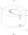
FIG. 1 is a schematic structural diagram of an electrochemical apparatus according to an embodiment of this application. -
FIG. 2 is a cross-sectional view of an electrochemical apparatus according to an embodiment of this application. -
FIG. 3 is a top view of an electrode assembly according to an embodiment of this application. -
FIG. 4 is a schematic diagram of generating an axial magnetic field by a winding structure according to this application. -
FIG. 5 is a curve diagram illustrating a relationship between an included angle θ and magnetic flux densities on the upper end surface and the lower end surface of the electrode assembly according to this application. -
FIG. 6 is a schematic diagram of a relationship between the magnetic flux density on the upper end surface and the number of winding turns according to this application. -
FIG. 7 is a schematic diagram of a relationship between the magnetic flux density on the lower end surface and the number of winding turns according to this application. -
FIG. 8 is a schematic structural diagram of an electrode assembly according to an embodiment of this application. -
FIG. 9 is a schematic structural diagram of an electrochemical apparatus according to an embodiment of this application. -
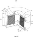
FIG. 10 is a cross-sectional view of an electrochemical apparatus according to an embodiment of this application. -
FIG. 11 is a schematic diagram of an electric device according to an embodiment of this application. -
Electric device 1000 Electrochemical apparatus 100 Electrode assembly 10 First electrode plate 11 First zone 111 Second electrode plate 12 Second zone 121 First side 13 Second side 14 Separator 15 First tab 20 First connecting portion 21 First extending portion 22 Second tab 30 Second connecting portion 31 Second extending portion 32 Electrode piece 40 Housing 50 Top wall 51 Side wall 52 Bottom wall 53 Conductive part 531 Accommodating space 54 Sealing piece 60 First connecting piece 70 Second connecting piece 80 Device body 200 - The following describes the technical solutions in the embodiments of this application with reference to the accompanying drawings in the embodiments of this application. Apparently, the described embodiments are only some rather than all of the embodiments of this application.
- It should be noted that, when one component is deemed as being "connected to" another component, it can be directly connected to the another component, or there can be a component in between. When one component is deemed as being "disposed on" another component, it can be directly disposed on the another component, or there can be a component in between. The terms "top", "bottom", "upper", "lower", "left", "right", "front", "rear", and other similar expressions as used herein are for illustration only.
- The term "perpendicular" is used to describe an ideal state between two parts. In the state of actual production or use, the two parts may be in an approximately perpendicular state. For example, combined with a numerical description, perpendicular may indicate that an included angle between two straight lines is 90±10°, or perpendicular may indicate that a dihedral angle of two planes is 90°±10°, or perpendicular may indicate that an included angle between a straight line and a plane is 90±10°. The two parts described as "being perpendicular" may not be absolute straight lines or planes, but may roughly be straight lines or planes. The parts extending as straight lines or planes in the overall direction can be considered as "straight lines" or "planes" from a macroscopic perspective.
- The term "parallel" is used to describe an ideal state between two parts. In the state of actual production or use, the two parts may be in an approximately parallel state. For example, combined with a numerical description, parallel may indicate that an included angle between two straight lines is 180°±10°, parallel may further indicate that a dihedral angle of two planes is 180°±10°, and parallel may still further indicate that an included angle between a straight line and a plane is 180°±10°. The two parts described as "being parallel" may not be absolute straight lines or planes, but may roughly be straight lines or planes. The parts extending as straight lines or planes in the overall direction can be considered as "straight lines" or "planes" from a macroscopic perspective.
- Unless otherwise defined, all technical and scientific terms used herein shall have the same meanings as commonly understood by those skilled in the art to which this application belongs. The terms used herein in the specification of this application are only used to describe specific embodiments, and are not intended to limit this application.
- This application discloses an electrochemical apparatus. The electrochemical apparatus includes an electrode assembly, where the electrode assembly is a winding structure, and the electrode assembly includes a first electrode plate and a second electrode plate. A winding end of the first electrode plate is provided with a first zone, the first zone is connected to a first tab. A winding end of the second electrode plate is provided with a second zone, the second zone is connected to a second tab. Along a winding direction from inside to outside of the winding structure, the first electrode plate is located on the inner side of the electrode assembly relative to the second electrode plate, and the first zone exceeds the second zone, the first zone exceeding the second zone by a winding length of less than one turn. As viewed along a width direction of the first electrode plate, an included angle between a half line from a winding center of the electrode assembly to a geometric center of the first zone and a half line from the winding center to a geometric center of the second zone is θ, satisfying 30°≤θ≤270°.
- The inventors of this application have found through research that batteries with the winding structure have a special spiral involute structure and a non-overlapping property of positive and negative electrode plates. In this case, an effective current path length of the first electrode plate located on an inner side of the winding structure is shorter than that of the second electrode plate located on an outer side of the winding structure to generate a strong axial magnetic field on both end surfaces of the winding body. In this application, an effective length of the outermost turn of the first electrode plate located on an inner side of the winding structure is extended to make the first zone exceed the second zone. When the electrode assembly is discharged and generates an electric current, a magnetic field produced by a part of the first electrode plate exceeding the second zone can at least partially cancel the magnetic field produced on two axial ends of the spiral involute structure. This effectively reduces the magnetic field produced by the winding structure of the electrode assembly and further reduces interference of the electrochemical apparatus on a surrounding electric device.
- The following describes some embodiments of this application with reference to the accompanying drawings. In absence of conflicts, the following embodiments and features in the embodiments can be combined with each other.
- Referring to
FIG. 1 to FIG. 3 , an embodiment of this application provides anelectrochemical apparatus 100. Theelectrochemical apparatus 100 includes anelectrode assembly 10, where theelectrode assembly 10 is a winding structure, and theelectrode assembly 10 includes afirst electrode plate 11 and asecond electrode plate 12. Along a winding direction from inside to outside of the winding structure, thefirst electrode plate 11 is located on the inner side of theelectrode assembly 10 relative to thesecond electrode plate 12. Afirst tab 20 is configured to connect to thefirst electrode plate 11, and asecond tab 30 is configured to connect to thesecond electrode plate 12. - A
separator 15 is disposed between thefirst electrode plate 11 and thesecond electrode plate 12. Thefirst electrode plate 11, theseparator 15, and thesecond electrode plate 12 are wound to form theelectrode assembly 10. Theseparator 15 is configured to isolate thefirst electrode plate 11 from thesecond electrode plate 12, reducing the risk of a short-circuit of theelectrochemical apparatus 100. - One of the
first electrode plate 11 and thesecond electrode plate 12 is a positive electrode plate, and the other one is a negative electrode plate. Thefirst tab 20 and thefirst electrode plate 11 have the same polarity, and thesecond tab 30 and thesecond electrode plate 12 have the same polarity. In some embodiments, thefirst tab 20 is a positive electrode tab, and thesecond tab 30 is a negative electrode tab. - In some embodiments, referring to
FIG. 3 , a winding end of thefirst electrode plate 11 is provided with afirst zone 111, thefirst zone 111 is configured to connect to thefirst tab 20. A winding end of thesecond electrode plate 12 is provided with asecond zone 121, thesecond zone 121 is configured to connect to thesecond tab 30. Along the winding direction from inside to outside of the winding structure, thefirst zone 111 exceeds thesecond zone 121, thefirst zone 111 exceeding thesecond zone 121 by a winding length of less than one turn. As viewed along a width direction of thefirst electrode plate 11, a half line from a winding center of theelectrode assembly 10 to a geometric center of thefirst zone 111 is L1, and a half line from the winding center of theelectrode assembly 10 to a geometric center of thesecond zone 121 is L2. An included angle between L1 and L2 is θ, satisfying: 30°≤θ≤270°. For ease of understanding and description, referring to an X direction and an A direction in the figure, the X direction is the width direction of thefirst electrode plate 11, and the A direction is the winding direction. - With reference to
FIG. 4 , the following equation holds for theelectrode assembly 10 with the winding structure.
- B is the magnetic flux density, which may be used to indicate strength of a magnetic field, R is a radius of a circle, and x is a distance from the center of the circle to a point on the axis. It can be seen from the foregoing equation that for a concentric winding structure, magnetic fields on the axis cannot be canceled completely, and a magnetic field of specific strength is always present.
- An effective length of the outermost turn of the
first electrode plate 11 is extended to make the winding end of thefirst electrode plate 11 exceed the winding end of thesecond electrode plate 12, and therefore thefirst zone 111 exceeds thesecond zone 121. When theelectrode assembly 10 is discharged and generates an electric current, a magnetic field produced by a part of thefirst electrode plate 11 exceeding thesecond zone 121 can at least partially cancel a magnetic field produced on two axial ends of a spiral involute structure formed by a plurality of layers of thefirst electrode plate 11 and thesecond electrode plate 12. This effectively reduces the magnetic field produced by the winding structure of theelectrode assembly 10, thereby reducing electromagnetic interference of theelectrochemical apparatus 100 on the surrounding electric device. - In some embodiments, along the winding direction from inside to outside of the winding structure, the number of winding turns of the
first electrode plate 11 is the same as the number of winding turns of thesecond electrode plate 12. The number of winding turns of thefirst electrode plate 11 or the number of winding turns of thesecond electrode plate 12 is the number of winding turns for theelectrode assembly 10, and the number of winding turns for theelectrode assembly 10 is n. - In other embodiments, along the winding direction from inside to outside of the winding structure, the winding end of the
first electrode plate 11 exceeds the winding end of the second electrode plate 12 (not shown in the figure). In some embodiments, a length of thefirst electrode plate 11 exceeds that of thesecond electrode plate 12 by more than one turn, so that the number of winding turns of thefirst electrode plate 11 is greater than the number of winding turns of thesecond electrode plate 12. - In other embodiments, along the winding direction from inside to outside of the winding structure, the winding end of the
second electrode plate 12 exceeds the winding end of the first electrode plate 11 (not shown in the figure). In some embodiments, thesecond electrode plate 12 exceeds thefirst electrode plate 11 by a length of more than one turn, so that the number of winding turns of thefirst electrode plate 11 is smaller than the number of winding turns of thesecond electrode plate 12. - In order to verify the effect on canceling the axial magnetic field produced by the
electrochemical apparatus 100 in this application, a number of comparative experiments were performed as follows. - The
first electrode plate 11 was used as a positive electrode plate, and thesecond electrode plate 12 was used as a negative electrode plate. The number of winding turns n for theelectrode assembly 10 was 17 layers. A position where thesecond electrode plate 12 and thesecond tab 30 are welded was changed so as to change the included angle θ. When the included angle θ was negative, thesecond zone 121 exceeded thefirst zone 111 along the winding direction from inside to outside of the winding structure. When the included angle was positive, thefirst zone 111 exceeded thesecond zone 121 along the winding direction from inside to outside of the winding structure. Magnetic flux densities on an upper end surface and a lower end surface in the axial direction of theelectrode assembly 10 were recorded for different included angles θ. The recorded results are shown in Table 1 andFIG. 5 .Table 1: Relationship between included angles θ and magnetic flux densities Included angle θ (°) Magnetic flux density B 1/10-6(T) on the upper end surface Magnetic flux density B2/10-6(T) on the lower end surface -330 -47.9 -58.4 -270 -40.5 -49.3 -210 -34.3 -41.8 -150 -29.0 -35.3 -120 -26.4 -32.1 -90 -23.7 -28.9 -60 -21.1 -25.7 -30 -18.4 -22.5 0 -15.6 -19.5 30 -12.9 -16.2 60 -10.2 -12.9 90 -7.50 -9.66 120 -5.07 -5.86 150 -2.10 -3.09 210 4.03 2.84 240 8.04 4.92 300 13.7 10.8 360 19.4 16.7 420 25.0 22.5 - Where, positive and negative values of the magnetic flux density represent opposite magnetic field directions.
- In some embodiments, referring to Table 1 and
FIG. 5 , the included angle θ satisfies 90°≤θ≤240°. When the included angle θ falls within this range, the magnetic field produced by the part of thefirst electrode plate 11 exceeding thesecond zone 121 can better cancel the magnetic field produced on the two axial ends of theelectrode assembly 10, further reducing the interference caused by theelectrochemical apparatus 100 on the surrounding electric device. - A plurality of
electrode assemblies 10 were provided. Eachelectrode assembly 10 had a different number of winding turns n. Experiment 1 was performed on eachelectrode assembly 10 to obtain results. Calculation was performed based on the result of each experiment and optimal included angles were recorded. Based on the specificed number of winding turns n in an experiment, the optimal included angle was an included angle when the magnetic flux densities on the upper end surface and the lower end surface of theelectrode assembly 10 were the smallest. The recorded results are shown in Table 2,FIG. 6 , andFIG. 7 .Table 2: Optimal included angles for different numbers of winding turns Number of winding turns n (layer) Optimal included angle θ1 (°) on the upper end surface Optimal included angle θ2 (°) on the lower end surface N1 17 165.21 185.12 N2 15 167.16 190.87 N3 13 164.00 192.71 N4 11 160.03 194.82 N5 9 165.50 187.78 N6 7 173.43 179.82 N7 5 136.49 203.43 N8 3 117.27 203.12 - In some embodiments, referring to Table 2,
FIG. 6 , andFIG. 7 , when 30°≤θ≤270° is satisfied, good demagnetization effects can still be achieved even for different numbers of winding turns n. When the number of winding turns n satisfies 3≤n≤40, good demagnetization effects are all achieved. - In some embodiments, referring to Table 2,
FIG. 6 , andFIG. 7 , the number of winding turns for theelectrode assembly 10 is n, and 7≤n≤40 is satisfied. When the number of winding turns n for theelectrode assembly 10 falls within the foregoing range, in a case that thefirst electrode plate 11 slightly exceeds thesecond zone 121, the magnetic field produced on the two axial ends of theelectrode assembly 10 by thefirst electrode plate 11 located on the inner side of the winding structure and thesecond electrode plate 12 located on the outer side of the winding structure can be better canceled. In this case, an energy density of theelectrochemical apparatus 100 is further increased while the interference caused by theelectrochemical apparatus 100 on the surrounding electric device can be further reduced. - In some embodiments, referring to
FIG. 8 , along the winding direction from inside to outside of the winding structure, a winding end of theseparator 15 exceeds thefirst electrode plate 11. This can reduce the risk of direct contact between thefirst electrode plate 11 and thesecond electrode plate 12 and thehousing 50. - In some embodiments, along the winding direction from inside to outside of the winding structure, the winding end of the
separator 15 is connected to thesecond electrode plate 12 by using a adhesive piece (not shown in the figure), so as to reduce the risk of curling the winding end of theseparator 15. The adhesive piece may be an insulation adhesive. - In some embodiments, referring to
FIG. 8 , along the width direction of thefirst electrode plate 11, theelectrode assembly 10 includes afirst side 13 and asecond side 14 disposed opposite to each other. Thefirst tab 20 includes a first connectingportion 21 and a first extendingportion 22, where the first connectingportion 21 is connected to thefirst zone 111, and the first extendingportion 22 is connected to the first connectingportion 21 and located on thefirst side 13. Thesecond tab 30 includes a second connectingportion 31 and a second extendingportion 32, where the second connectingportion 31 is connected to thesecond zone 121, and the second extendingportion 32 is connected to the second connectingportion 31 and located on thesecond side 14. - The
first tab 20 and thesecond tab 30 are located on opposite sides of theelectrode assembly 10 respectively. This can reduce the risk of mutual interference between thefirst tab 20 and thesecond tab 30 while facilitating installation of theelectrode assembly 10. - In some embodiments, referring to
FIG. 9 andFIG. 10 , the first connectingportion 21 and the first extendingportion 22 are arranged at an included angle. In some embodiments, the second connectingportion 31 and the second extendingportion 32 are arranged at an included angle. - In some embodiments, referring to
FIG. 10 , theelectrochemical apparatus 100 further includes ahousing 50, and thehousing 50 includes atop wall 51, aside wall 52, and abottom wall 53. Thetop wall 51 and thebottom wall 53 are connected to theside wall 52. Thetop wall 51, theside wall 52, and thebottom wall 53 enclose anaccommodating space 54. Theelectrode assembly 10, thefirst tab 20, and thesecond tab 30 are all accommodated in theaccommodating space 54. Thehousing 50 can protect theelectrode assembly 10, reducing the risk of thefirst electrode plate 11 and thesecond electrode plate 12 being in direct contact with an external structure. - In some embodiments, referring to
FIG. 10 , theelectrochemical apparatus 100 further includes anelectrode piece 40. A part of theelectrode piece 40 is disposed inside theaccommodating space 54 for connecting to the first extendingportion 22, so that theelectrode piece 40 is connected to thefirst tab 20. A part of theelectrode piece 40 is disposed outside theaccommodating space 54. Theelectrode piece 40 may be in a shape of a column, a hemisphere, a sheet, or a combination of these shapes, which is not specifically limited herein. - In some embodiments, referring to
FIG. 10 , theelectrochemical apparatus 100 further includes a sealingpiece 60. The sealingpiece 60 is disposed between theelectrode piece 40 and thehousing 50. Theelectrode piece 40 is insulatively connected to thetop wall 51 through the sealingpiece 60, thereby reducing the risk of a short-circuit of theelectrochemical apparatus 100. Theelectrode piece 40 may be copper, iron, or another conductive metal, and the sealingpiece 60 may be a sealant. - In some embodiments, an insulator (not shown in the figure) is disposed in the
accommodating space 54 and located between theelectrode assembly 10 and thehousing 50. The insulator can isolate two ends of thefirst electrode plate 11 in the width direction from thehousing 50, thereby reducing the risk of a short-circuit inside theelectrochemical apparatus 100. - In some embodiments, a
conductive part 531 is disposed on thebottom wall 53. The second extendingportion 32 is connected to theconductive part 531, so that thesecond tab 30 is electrically connected to theconductive part 531. In some embodiments, theconductive part 531 may be copper, iron, or another conductive metal. - In some embodiments, referring to
FIG. 10 , theelectrochemical apparatus 100 further includes a first connectingpiece 70 and a second connectingpiece 80. At least part of the first connectingpiece 70 is located outside theaccommodating space 54 and connected to theelectrode piece 40, so that the first connectingpiece 70 is electrically connected to thefirst tab 20. At least part of the second connectingpiece 80 is located outside theaccommodating space 54 and electrically connected to theconductive part 531, so that the second connectingpiece 80 is electrically connected to thesecond tab 30. - Referring to
FIG. 11 , an embodiment of this application further provides anelectric device 1000. Theelectric device 1000 includes adevice body 200 and theelectrochemical apparatus 100. With the technical solution in any one of the embodiments of theelectrochemical apparatus 100, theelectric device 1000 at least has the beneficial effects brought by the technical solution of any one of the embodiments of theelectrochemical apparatus 100, which are not described herein again. - Where, the first connecting
piece 70 and the second connectingpiece 80 of theelectrochemical apparatus 100 can be electrically connected to thedevice body 200 of theelectric device 1000, so that theelectrochemical apparatus 100 can be electrically connected to thedevice body 200 and supply electricity to thedevice body 200. - The
electric device 1000 in this application may be but is not limited to a clock, an illuminating lamp, a calculator, a headset, an electronic book player, a toy, a game console, a video recorder, a notebook computer, a tablet computer, a portable telephone, a portable CD player, an electronic notebook, a portable recorder, or a radio. - In addition, those of ordinary skill in the art should be aware of that the foregoing embodiments are only intended to describe this application, but not to limit this application. Appropriate modifications and variations made to the foregoing embodiments without departing from the essential spirit and scope of this application all fall within the scope of this application.
Claims (10)
- An electrochemical apparatus, comprising an electrode assembly, wherein the electrode assembly is a winding structure, and the electrode assembly comprises:a first electrode plate, wherein a winding end of the first electrode plate is provided with a first zone, and the first zone is connected to a first tab; anda second electrode plate, wherein a winding end of the second electrode plate is provided with a second zone, and the second zone is connected to a second tab;characterized in that:along a winding direction from inside to outside of the winding structure, the first electrode plate is located on the inner side of the electrode assembly relative to the second electrode plate, and the first zone exceeds the second zone, the first zone exceeding the second zone by a winding length of less than one turn; andas viewed along a width direction of the first electrode plate, an included angle between a half line from a winding center of the electrode assembly to a geometric center of the first zone and a half line from the winding center to a geometric center of the second zone is θ, satisfying: 30°≤θ≤270°.
- The electrochemical apparatus according to claim 1, characterized in that, 90°≤θ≤240°.
- The electrochemical apparatus according to claim 1, characterized in that, the number of winding turns for the electrode assembly is n, satisfying: 3≤n≤40.
- The electrochemical apparatus according to claim 3, characterized in that, 7≤n≤40.
- The electrochemical apparatus according to claim 1, characterized in that, the first electrode plate is a positive electrode plate, and the second electrode plate is a negative electrode plate.
- The electrochemical apparatus according to claim 1, characterized in that, along the width direction of the first electrode plate, the electrode assembly comprises a first side and a second side disposed opposite to each other;the first tab comprises a first connecting portion and a first extending portion, wherein the first connecting portion is connected to the first zone, and the first extending portion is connected to the first connecting portion and located on the first side; andthe second tab comprises a second connecting portion and a second extending portion, wherein the second connecting portion is connected to the second zone, and the second extending portion is connected to the second connecting portion and located on the second side.
- The electrochemical apparatus according to claim 6, characterized in that, the electrochemical apparatus further comprises an electrode piece and a housing, the electrode assembly is disposed inside the housing, the first extending portion is connected to the electrode piece, and the second extending portion is connected to the housing.
- The electrochemical apparatus according to claim 1, characterized in that, the electrode assembly further comprises a separator, the separator is disposed between the first electrode plate and the second electrode plate, and along the winding direction from inside to outside of the winding structure, a winding end of the separator exceeds the first electrode plate.
- The electrochemical apparatus according to claim 7, characterized in that, the electrochemical apparatus further comprises an insulator, and the insulator is disposed between the housing and the electrode assembly.
- An electric device, characterized in that, comprising the electrochemical apparatus according to any one of claims 1 to 9.
Applications Claiming Priority (2)
| Application Number | Priority Date | Filing Date | Title |
|---|---|---|---|
| CN202210209795.1A CN114583236A (en) | 2022-03-04 | 2022-03-04 | Electrochemical device and electric equipment |
| PCT/CN2023/076839 WO2023165349A1 (en) | 2022-03-04 | 2023-02-17 | Electrochemical apparatus and electrical device |
Publications (2)
| Publication Number | Publication Date |
|---|---|
| EP4401184A1 true EP4401184A1 (en) | 2024-07-17 |
| EP4401184A4 EP4401184A4 (en) | 2025-08-20 |
Family
ID=81774159
Family Applications (1)
| Application Number | Title | Priority Date | Filing Date |
|---|---|---|---|
| EP23762750.0A Pending EP4401184A4 (en) | 2022-03-04 | 2023-02-17 | ELECTROCHEMICAL DEVICE AND ELECTRICAL DEVICE |
Country Status (4)
| Country | Link |
|---|---|
| US (1) | US20240243340A1 (en) |
| EP (1) | EP4401184A4 (en) |
| CN (1) | CN114583236A (en) |
| WO (1) | WO2023165349A1 (en) |
Families Citing this family (4)
| Publication number | Priority date | Publication date | Assignee | Title |
|---|---|---|---|---|
| CN114583236A (en) * | 2022-03-04 | 2022-06-03 | 宁德新能源科技有限公司 | Electrochemical device and electric equipment |
| KR20260008200A (en) * | 2023-06-29 | 2026-01-15 | 닝더 엠프렉스 테크놀로지 리미티드 | Electrochemical devices and electrical appliances |
| WO2025000363A1 (en) * | 2023-06-29 | 2025-01-02 | 宁德新能源科技有限公司 | Electrochemical apparatus and electrical device |
| WO2025030287A1 (en) * | 2023-08-04 | 2025-02-13 | 宁德新能源科技有限公司 | Electrochemical apparatus, electrical device, and preparation method for electrochemical apparatus |
Family Cites Families (13)
| Publication number | Priority date | Publication date | Assignee | Title |
|---|---|---|---|---|
| US9240610B2 (en) * | 2009-11-23 | 2016-01-19 | Blackberry Limited | Rechargeable battery with reduced magnetic leak |
| JP5912271B2 (en) * | 2011-03-16 | 2016-04-27 | トヨタ自動車株式会社 | Secondary battery |
| CN204577529U (en) * | 2015-04-29 | 2015-08-19 | 山西恒昌元科技有限公司 | A kind of cylindrical lithium ion battery pole piece winding-structure |
| CN110611116A (en) * | 2019-09-26 | 2019-12-24 | 广东微电新能源有限公司 | An electrode sheet for a battery core and a cylindrical or button battery |
| WO2022126414A1 (en) * | 2020-12-16 | 2022-06-23 | 宁德新能源科技有限公司 | Battery and electronic device having the battery |
| CN112615039B (en) * | 2020-12-31 | 2022-05-17 | 广东微电新能源有限公司 | Cell structure, battery and electronic device |
| CN214706178U (en) * | 2021-03-26 | 2021-11-12 | 比亚迪股份有限公司 | Button Battery |
| CN215418508U (en) * | 2021-06-03 | 2022-01-04 | 万魔声学股份有限公司 | Novel battery with tab structure and TWS earphone |
| CN113381079B (en) * | 2021-06-08 | 2022-07-08 | 歌尔科技有限公司 | Winding type battery and TWS Bluetooth headset |
| CN113710081B (en) * | 2021-08-26 | 2023-06-09 | 维沃移动通信有限公司 | Batteries and Electronics |
| CN215644894U (en) * | 2021-09-16 | 2022-01-25 | 歌尔科技有限公司 | Battery and bluetooth headset |
| CN114006021B (en) * | 2021-10-29 | 2023-07-07 | 宁德新能源科技有限公司 | Electrochemical devices and electrical equipment |
| CN114583236A (en) * | 2022-03-04 | 2022-06-03 | 宁德新能源科技有限公司 | Electrochemical device and electric equipment |
-
2022
- 2022-03-04 CN CN202210209795.1A patent/CN114583236A/en active Pending
-
2023
- 2023-02-17 WO PCT/CN2023/076839 patent/WO2023165349A1/en not_active Ceased
- 2023-02-17 EP EP23762750.0A patent/EP4401184A4/en active Pending
-
2024
- 2024-03-29 US US18/622,150 patent/US20240243340A1/en active Pending
Also Published As
| Publication number | Publication date |
|---|---|
| CN114583236A (en) | 2022-06-03 |
| US20240243340A1 (en) | 2024-07-18 |
| WO2023165349A1 (en) | 2023-09-07 |
| EP4401184A4 (en) | 2025-08-20 |
Similar Documents
| Publication | Publication Date | Title |
|---|---|---|
| US20240243340A1 (en) | Electrochemical apparatus and electric device | |
| US9698405B2 (en) | Electric connector and battery comprising the same | |
| US12315960B2 (en) | Current collecting member and manufacturing method thereof, secondary battery and manufacturing method thereof, battery module, and apparatus | |
| CN215184263U (en) | Battery packs and electronic devices | |
| US11749861B2 (en) | Battery box and battery module | |
| US20240283107A1 (en) | Electrochemical apparatus and electric device | |
| US20240274993A1 (en) | Electrochemical apparatus and electric device | |
| WO2024087957A1 (en) | Wound battery cell, battery, battery assembly, and electrical apparatus | |
| CN211654934U (en) | Battery and electronic device having the same | |
| EP4228049A1 (en) | Battery and electronic device having same | |
| CN217035892U (en) | Battery and electronic device | |
| CN216288852U (en) | Electrochemical device and electric equipment | |
| KR20170027546A (en) | Cell module for secondary battery pack and assembly method for the same | |
| US20220223918A1 (en) | Secondary battery and battery module | |
| WO2023115544A1 (en) | Insulating sheet, cell, battery and electric device | |
| CN114006021B (en) | Electrochemical devices and electrical equipment | |
| US20260128479A1 (en) | Electrochemical apparatus and electrical device | |
| CN221283422U (en) | Electronic equipment and ultrathin mobile power supply | |
| CN216818480U (en) | Button cell elastic sheet and corresponding button cell | |
| CN111403670A (en) | Battery and electric device with same | |
| CN223347906U (en) | Secondary battery and electricity utilization device | |
| US20260128477A1 (en) | Electrochemical apparatus and electric device | |
| CN220042204U (en) | Battery and battery device | |
| CN216818560U (en) | Button cell elastic sheet capable of being firmly mounted and corresponding button cell | |
| KR20260039800A (en) | Electrochemical devices and electrical equipment |
Legal Events
| Date | Code | Title | Description |
|---|---|---|---|
| STAA | Information on the status of an ep patent application or granted ep patent |
Free format text: STATUS: THE INTERNATIONAL PUBLICATION HAS BEEN MADE |
|
| PUAI | Public reference made under article 153(3) epc to a published international application that has entered the european phase |
Free format text: ORIGINAL CODE: 0009012 |
|
| STAA | Information on the status of an ep patent application or granted ep patent |
Free format text: STATUS: REQUEST FOR EXAMINATION WAS MADE |
|
| 17P | Request for examination filed |
Effective date: 20240328 |
|
| AK | Designated contracting states |
Kind code of ref document: A1 Designated state(s): AL AT BE BG CH CY CZ DE DK EE ES FI FR GB GR HR HU IE IS IT LI LT LU LV MC ME MK MT NL NO PL PT RO RS SE SI SK SM TR |
|
| DAV | Request for validation of the european patent (deleted) | ||
| DAX | Request for extension of the european patent (deleted) | ||
| A4 | Supplementary search report drawn up and despatched |
Effective date: 20250718 |
|
| RIC1 | Information provided on ipc code assigned before grant |
Ipc: H01M 10/04 20060101AFI20250714BHEP Ipc: H01M 10/052 20100101ALI20250714BHEP Ipc: H01M 10/0587 20100101ALI20250714BHEP Ipc: H01M 50/531 20210101ALI20250714BHEP |