EP4401180A1 - Battery module and battery pack including the same - Google Patents
Battery module and battery pack including the same Download PDFInfo
- Publication number
- EP4401180A1 EP4401180A1 EP23209718.8A EP23209718A EP4401180A1 EP 4401180 A1 EP4401180 A1 EP 4401180A1 EP 23209718 A EP23209718 A EP 23209718A EP 4401180 A1 EP4401180 A1 EP 4401180A1
- Authority
- EP
- European Patent Office
- Prior art keywords
- flow path
- battery
- cooling
- cooling plate
- battery module
- Prior art date
- Legal status (The legal status is an assumption and is not a legal conclusion. Google has not performed a legal analysis and makes no representation as to the accuracy of the status listed.)
- Pending
Links
Images




Classifications
-
- H—ELECTRICITY
- H01—ELECTRIC ELEMENTS
- H01M—PROCESSES OR MEANS, e.g. BATTERIES, FOR THE DIRECT CONVERSION OF CHEMICAL ENERGY INTO ELECTRICAL ENERGY
- H01M10/00—Secondary cells; Manufacture thereof
- H01M10/60—Heating or cooling; Temperature control
- H01M10/61—Types of temperature control
- H01M10/613—Cooling or keeping cold
-
- H—ELECTRICITY
- H01—ELECTRIC ELEMENTS
- H01M—PROCESSES OR MEANS, e.g. BATTERIES, FOR THE DIRECT CONVERSION OF CHEMICAL ENERGY INTO ELECTRICAL ENERGY
- H01M10/00—Secondary cells; Manufacture thereof
- H01M10/04—Construction or manufacture in general
- H01M10/0468—Compression means for stacks of electrodes and separators
-
- H—ELECTRICITY
- H01—ELECTRIC ELEMENTS
- H01M—PROCESSES OR MEANS, e.g. BATTERIES, FOR THE DIRECT CONVERSION OF CHEMICAL ENERGY INTO ELECTRICAL ENERGY
- H01M10/00—Secondary cells; Manufacture thereof
- H01M10/60—Heating or cooling; Temperature control
- H01M10/64—Heating or cooling; Temperature control characterised by the shape of the cells
- H01M10/647—Prismatic or flat cells, e.g. pouch cells
-
- H—ELECTRICITY
- H01—ELECTRIC ELEMENTS
- H01M—PROCESSES OR MEANS, e.g. BATTERIES, FOR THE DIRECT CONVERSION OF CHEMICAL ENERGY INTO ELECTRICAL ENERGY
- H01M10/00—Secondary cells; Manufacture thereof
- H01M10/60—Heating or cooling; Temperature control
- H01M10/65—Means for temperature control structurally associated with the cells
- H01M10/655—Solid structures for heat exchange or heat conduction
- H01M10/6551—Surfaces specially adapted for heat dissipation or radiation, e.g. fins or coatings
-
- H—ELECTRICITY
- H01—ELECTRIC ELEMENTS
- H01M—PROCESSES OR MEANS, e.g. BATTERIES, FOR THE DIRECT CONVERSION OF CHEMICAL ENERGY INTO ELECTRICAL ENERGY
- H01M10/00—Secondary cells; Manufacture thereof
- H01M10/60—Heating or cooling; Temperature control
- H01M10/65—Means for temperature control structurally associated with the cells
- H01M10/655—Solid structures for heat exchange or heat conduction
- H01M10/6554—Rods or plates
-
- H—ELECTRICITY
- H01—ELECTRIC ELEMENTS
- H01M—PROCESSES OR MEANS, e.g. BATTERIES, FOR THE DIRECT CONVERSION OF CHEMICAL ENERGY INTO ELECTRICAL ENERGY
- H01M10/00—Secondary cells; Manufacture thereof
- H01M10/60—Heating or cooling; Temperature control
- H01M10/65—Means for temperature control structurally associated with the cells
- H01M10/655—Solid structures for heat exchange or heat conduction
- H01M10/6556—Solid parts with flow channel passages or pipes for heat exchange
-
- H—ELECTRICITY
- H01—ELECTRIC ELEMENTS
- H01M—PROCESSES OR MEANS, e.g. BATTERIES, FOR THE DIRECT CONVERSION OF CHEMICAL ENERGY INTO ELECTRICAL ENERGY
- H01M10/00—Secondary cells; Manufacture thereof
- H01M10/60—Heating or cooling; Temperature control
- H01M10/65—Means for temperature control structurally associated with the cells
- H01M10/656—Means for temperature control structurally associated with the cells characterised by the type of heat-exchange fluid
- H01M10/6567—Liquids
-
- H—ELECTRICITY
- H01—ELECTRIC ELEMENTS
- H01M—PROCESSES OR MEANS, e.g. BATTERIES, FOR THE DIRECT CONVERSION OF CHEMICAL ENERGY INTO ELECTRICAL ENERGY
- H01M10/00—Secondary cells; Manufacture thereof
- H01M10/60—Heating or cooling; Temperature control
- H01M10/65—Means for temperature control structurally associated with the cells
- H01M10/656—Means for temperature control structurally associated with the cells characterised by the type of heat-exchange fluid
- H01M10/6567—Liquids
- H01M10/6568—Liquids characterised by flow circuits, e.g. loops, located externally to the cells or cell casings
-
- H—ELECTRICITY
- H01—ELECTRIC ELEMENTS
- H01M—PROCESSES OR MEANS, e.g. BATTERIES, FOR THE DIRECT CONVERSION OF CHEMICAL ENERGY INTO ELECTRICAL ENERGY
- H01M10/00—Secondary cells; Manufacture thereof
- H01M10/60—Heating or cooling; Temperature control
- H01M10/65—Means for temperature control structurally associated with the cells
- H01M10/658—Means for temperature control structurally associated with the cells by thermal insulation or shielding
-
- H—ELECTRICITY
- H01—ELECTRIC ELEMENTS
- H01M—PROCESSES OR MEANS, e.g. BATTERIES, FOR THE DIRECT CONVERSION OF CHEMICAL ENERGY INTO ELECTRICAL ENERGY
- H01M50/00—Constructional details or processes of manufacture of the non-active parts of electrochemical cells other than fuel cells, e.g. hybrid cells
- H01M50/20—Mountings; Secondary casings or frames; Racks, modules or packs; Suspension devices; Shock absorbers; Transport or carrying devices; Holders
- H01M50/204—Racks, modules or packs for multiple batteries or multiple cells
-
- H—ELECTRICITY
- H01—ELECTRIC ELEMENTS
- H01M—PROCESSES OR MEANS, e.g. BATTERIES, FOR THE DIRECT CONVERSION OF CHEMICAL ENERGY INTO ELECTRICAL ENERGY
- H01M50/00—Constructional details or processes of manufacture of the non-active parts of electrochemical cells other than fuel cells, e.g. hybrid cells
- H01M50/20—Mountings; Secondary casings or frames; Racks, modules or packs; Suspension devices; Shock absorbers; Transport or carrying devices; Holders
- H01M50/204—Racks, modules or packs for multiple batteries or multiple cells
- H01M50/207—Racks, modules or packs for multiple batteries or multiple cells characterised by their shape
- H01M50/209—Racks, modules or packs for multiple batteries or multiple cells characterised by their shape adapted for prismatic or rectangular cells
-
- H—ELECTRICITY
- H01—ELECTRIC ELEMENTS
- H01M—PROCESSES OR MEANS, e.g. BATTERIES, FOR THE DIRECT CONVERSION OF CHEMICAL ENERGY INTO ELECTRICAL ENERGY
- H01M50/00—Constructional details or processes of manufacture of the non-active parts of electrochemical cells other than fuel cells, e.g. hybrid cells
- H01M50/20—Mountings; Secondary casings or frames; Racks, modules or packs; Suspension devices; Shock absorbers; Transport or carrying devices; Holders
- H01M50/258—Modular batteries; Casings provided with means for assembling
-
- Y—GENERAL TAGGING OF NEW TECHNOLOGICAL DEVELOPMENTS; GENERAL TAGGING OF CROSS-SECTIONAL TECHNOLOGIES SPANNING OVER SEVERAL SECTIONS OF THE IPC; TECHNICAL SUBJECTS COVERED BY FORMER USPC CROSS-REFERENCE ART COLLECTIONS [XRACs] AND DIGESTS
- Y02—TECHNOLOGIES OR APPLICATIONS FOR MITIGATION OR ADAPTATION AGAINST CLIMATE CHANGE
- Y02E—REDUCTION OF GREENHOUSE GAS [GHG] EMISSIONS, RELATED TO ENERGY GENERATION, TRANSMISSION OR DISTRIBUTION
- Y02E60/00—Enabling technologies; Technologies with a potential or indirect contribution to GHG emissions mitigation
- Y02E60/10—Energy storage using batteries
Definitions
- the technology and implementations disclosed in this patent document generally relate to a battery module and a battery pack including the same.
- Secondary batteries can charge and discharge repeatedly because of the reversible mutual conversion between chemical energy and electrical energy.
- Secondary batteries may be used as an energy source for electric vehicles, hybrid vehicles, energy storage systems (ESSs), and mobile devices.
- ESSs energy storage systems
- An aspect of the disclosed technology is to provide a battery module having improved cooling performance and efficiency and a battery pack including the same.
- An aspect of the disclosed technology is to provide a battery pack preventing or delaying propagation of heat between battery modules.
- a battery module may include: a plurality of battery cells arranged in a row one direction; an end plate disposed adjacent to an outermost battery cell of the plurality of battery cells; and an upper cooling plate and a lower cooling plate disposed above and below the plurality of battery cells, respectively, and structured to include a first cooling flow path and a second cooling flow path , respectively, for a coolant for cooling the plurality of battery cells to flow, wherein the end plate may include a flow path connection portion connected between the upper cooling plate and the lower cooling plate for the coolant to flow between the first cooling flow path and the second cooling flow path.
- the battery module may further include: an inlet connected to at least one of the first cooling flow path, the second cooling flow path, or the at least one flow path connection portion to supply the coolant into the first and second cooling flow paths and the at least one flow path connection portion, and an outlet to at least one of the first cooling flow path, the second cooling flow path, or the at least one flow path connection portion to discharge the coolant from the first and second cooling flow paths and the at least one flow path connection portion.
- the inlet and the outlet may be disposed on at least one of the upper cooling plate and the lower cooling plate.
- the flow path connection portion may include a pair of flow path connection portions disposed to be spaced apart from each other the one direction of the plurality of battery cells.
- the upper cooling plate or the lower cooling plate including the inlet and the outlet may include a first portion including a cooling flow path connected to the inlet, and a second portion including a cooling flow path connected to the outlet, wherein the first portion and the second portion may be separated and spaced apart from each other on the upper cooling plate or the lower cooling plate.
- the second portion may have an area at least the same as or greater than that of the first portion.
- one of the first cooling flow path or the second cooling flow path may not include the inlet and the outlet, wherein all parts of the one of the first cooling flow path or the second cooling flow path may be coupled to each other.
- the pair of flow path connection portions may include a first flow path connection portion and a second flow path connection portion, wherein the first flow path connection portion may be structured to allow the coolant to flow from the upper cooling plate to the lower cooling plate, and the second flow path connection portion may be structured to allow the coolant to flow from the lower cooling plate to the upper cooling plate.
- the battery module may further include: a heat dissipation member disposed between the plurality of battery cells and the upper cooling plate and the lower cooling plate may be further included.
- the plurality of battery cells may include prismatic battery cells each of which includes an electrode terminals on both sides of each of the plurality of battery cells.
- a battery pack may include: a plurality of battery modules of any one of described above; a pack housing structured to accommodate the battery module; and a pack cover coupled to the pack housing to cover the battery module.
- the inlet and the outlet may be exposed externally through the pack cover, and may further include a pipe joint coupled to the inlet and the outlet exposed through the pack cover, wherein the battery pack, may further include: a pipe joint coupled to the inlet and the outlet exposed through the pack cover.
- the inlet and the outlet may be arranged on one side of the battery module, wherein the plurality of battery modules may be accommodated in the pack housing, and the inlet and the outlet may be disposed close to each other between battery modules.
- a side surface of the battery module may be spaced apart from the pack housing, and an air gap may be formed between the battery module and the pack housing.
- the battery pack may further include: a heat insulation member disposed on at least one of a space between the battery module and the pack housing or a space between the battery module and the pack cover may be further included.
- Secondary batteries are widely used in various applications in part because they can be recharged and may be configured in various configurations with battery cells in various forms such as flexible pouch-type battery cells, or prismatic or cylindrical can-type rigid battery cells. Those battery cells are electrically connected in ways to provide desired electrical power output. Electric vehicles requiring high power may use a battery module that includes one or more cell stacks, each of which includes a plurality of battery cells stacked and electrically connected, or may use a battery pack that includes one or more battery modules that are electrically connected.
- the performance of secondary batteries may be affected by temperature.
- the temperature of secondary batteries when the temperature of secondary batteries is higher than a proper temperature, the performance of secondary batteries is degraded, and in severe cases, the increase in the temperature of secondary batteries may lead to explosion and ignition.
- Battery modules including a plurality of battery cells or battery packs including a plurality of battery modules may increase the risk of explosion and ignition.
- the disclosed technology can be implemented in some embodiments to provide battery module and battery pack structures that can control heat generated in the battery cells.
- FIG. 1 illustrates a cooling structure of an example battery pack
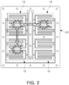
- FIG. 2 illustrates an example cooling plate of FIG. 1 .
- a plurality of battery modules 10 can be cooled by using a cooling plate 20 disposed below the plurality of battery modules 10 constituting the battery pack 1.
- this structure may have limitations in improving cooling performance and efficiency because cooling is performed only on one side of the battery module 10.
- FIG. 2 since the plurality of battery modules 10 shares the cooling plate 20, heat transfer between adjacent modules may cause thermal runaway.
- the disclosed technology can be implemented in some embodiments to provide a battery module 100 and a battery pack 1000 including the battery module 100 to perform cooling is performed on both surfaces of the battery module 100 and/or the battery pack 1000.
- the disclosed technology can be implemented in some embodiments to provide a battery module as will be described with reference to FIGS. 3 to 9 .
- FIG. 3 is a schematic perspective view of a battery module based on an embodiment of the disclosed technology.
- FIGS. 4 and 5 are example side views of the battery module of FIG. 3 .
- a battery module 100 may include a plurality of battery cells 110 and a plurality of cooling plates 130 and 140 configured to cool the plurality of battery cells 110.
- the plurality of battery cells 110 may be prismatic battery cells.
- the prismatic battery cell may include a case 111 structured to accommodate an electrode assembly and an electrolyte.
- the case 111 may have a flat and angular shape.
- the case 111 of the prismatic battery cell may include an aluminum material.
- the plurality of battery cells 110 may have a shape in which electrode terminals protrude on both sides in a longitudinal direction.
- a positive terminal 112 may be formed to protrude on one side of the plurality of battery cells 110 in the longitudinal direction
- a negative terminal 113 may be formed to protrude on the other side of the plurality of battery cells 110.
- the plurality of battery cells 110 may be electrically connected to the outside through electrode terminals.
- the plurality of battery cells 110 may be arranged in a row in one direction. In an implementation, the plurality of battery cells 110 may be stacked in one direction. For example, the plurality of battery cells 110 may be arranged or stacked such that a wide surface of the case 111 face each other. In one example, the plurality of battery cells 110 may be arranged or stacked such that positive terminals and negative terminals are alternately disposed in a stacking direction as shown in FIG. 3 .
- a compression member (not shown) may be disposed between the plurality of battery cells 110 to fill a gap between the plurality of battery cells 110.
- the compression member may be formed of a polyurethane material.
- the battery module 100 may include an end plate 120 disposed on an outermost side of the plurality of battery cells 110 in a stacking direction.
- the end plate 120 may be disposed on both sides of the plurality of battery cells 110 in the stacking direction.
- the end plate 120 may fix and support the plurality of battery cells 110 in the stacking direction of the plurality of battery cells 110.
- the end plate 120 Since the end plate 120 forms an exterior of the battery module 100, the end plate 120 should have structural rigidity, and at the same time, the end plate 120 should be able to prevent electrical short circuits caused by contact with the plurality of battery cells 110 and to absorb shocks.
- the end plate 120 may include a metal material and an insulating material, and a portion of the metal material and a portion of the insulating material may be integrally formed or separately formed.
- a side plate (not shown) may be disposed on both sides of the plurality of battery cells 110 in a longitudinal direction, respectively.
- the battery module 100 may include a plurality of cooling plates 130 and 140 cooling the plurality of battery cells 110.
- the plurality of cooling plates 130 and 140 may be respectively disposed above and below the plurality of battery cells 110, and thus, cooling (e.g., thermal management) may be performed on both surfaces of the plurality of battery cells 110.
- the plurality of cooling plates 130 and 140 may be formed of a metal material having high thermal conductivity.
- the plurality of cooling plates 130 and 140 may be formed of an aluminum or stainless steel material.
- a cooling plate disposed above the plurality of battery cells 110 is referred to as an upper cooling plate 130
- a cooling plate disposed below the plurality of battery cells 110 is referred to as a lower cooling plate 140.
- the upper cooling plate 130 and the lower cooling plate 140 may be disposed to cover upper and lower portions of the plurality of battery cells 110, respectively. In some implementations, the upper cooling plate 130 and the lower cooling plate 140 may directly face the upper and lower portions of the plurality of battery cells 110, respectively.
- a heat dissipation member (not shown) may be additionally disposed between the plurality of battery cells 110 and the upper cooling plate 130 and the lower cooling plate 140.
- the heat dissipation member may be provided with a thermal pad or thermal paste. The heat dissipation member may contribute to improving cooling performance and efficiency of the battery module 100 by filling a minute gap that may exist between the plurality of battery cells 110 and the upper cooling plate 130 and the lower cooling plate 140.
- the upper cooling plate 130 and the lower cooling plate 140 may include a cooling flow path (hereinafter, an upper cooling flow path 131 and a lower cooling flow path 141) through which a coolant such as cooling water for cooling the plurality of battery cells 110, flows.
- the upper cooling flow path 131 and the lower cooling flow path 141 may be formed on a whole surface of the upper cooling plate 130 and the lower cooling plate 140 so that heat exchange can be sufficiently performed on both surfaces of the plurality of battery cells 110.
- the upper cooling flow path 131 and the lower cooling flow path 141 may be connected to each other.
- the battery module 100 based on an embodiment of the disclosed technology may include a flow path connection portion 150 connecting the upper cooling flow path 131 and the lower cooling flow path 141.
- the flow path connection portion 150 may be disposed on the end plate 120.
- the flow path connection portion 150 may extend in a height direction of the end plate 120, so that one side of the flow path connection portion 150 may be connected to the upper cooling plate 130, and the other side thereof may be connected to the lower cooling plate 140.
- the flow path connection portion 150 may include a connection pipe 151, one side of the connection pipe 151 may communicate with the upper cooling passage 131 and the other side communicate with the lower cooling flow path 141, so that cooling water may flow from the cooling plate 130 to the lower cooling plate 140 and/or vice versa.
- the flow path connection portion 150 may further include a rubber hose 152 surrounding the connection pipe 151 and a clamp 153 fixing the rubber hose 152.
- the rubber horse 152 may be provided to surround substantially an entirety of the connection pipe 151, and the clamp 153 may be inserted into both ends of the rubber hose 152 to fix the rubber hose 152 to the connection pipe 151.
- a pair of flow path connection portions 150 may be provided.
- the battery module 100 based on an embodiment of the disclosed technology may include a pair of flow path connection portions 150.
- the pair of flow path connection portions 150 may be disposed to be spaced apart from each other in a longitudinal direction of the plurality of battery cells 110.
- the pair of flow path connection portions 150 may be disposed to be spaced apart from the outside of the end plate 120 in the longitudinal direction of the plurality of battery cells 110 on the outside of the end plate 120 in a stacking direction of the plurality of battery cells 110.
- the pair of flow path connection portions 150 may be disposed to provide a flow of coolant such as cooling water from a direction of the upper cooling plate 130 to a direction of the lower cooling plate 140 and/or in an opposite direction thereof. Therefore, as will be described later, in an embodiment in which the upper cooling plate 130 and the lower cooling plate 140 include any one of the inlet 160 and the outlet 170, respectively, the flow path connection portions 150 are not necessarily provided in a pair.
- the battery module 100 may include an inlet 160 supplying cooling water to the upper cooling plate 130 or the lower cooling plate 140, and an outlet 170 discharging cooling water externally of the battery module 100. That is, the inlet 160 and the outlet 170 may communicate with cooling flow paths 131 and 141 of the cooling plates 130 and 140.
- the inlet 160 and the outlet 170 may be disposed together on the upper cooling plate 130 or the lower cooling plate 140.
- the inlet 160 and the outlet 170 are disposed on the upper cooling plate 130, but as described above, the inlet 160 and the outlet 170 may be disposed on the lower cooling plate 140 instead of the upper cooling plate 130.
- the inlet 160 and the outlet 170 may be separately disposed on the upper cooling plate 130 and the lower cooling plate 140. That is, the inlet 160 may be disposed on the upper cooling plate 130 and the outlet 170 may be disposed on the lower cooling plate 140.
- the inlet 160 may be disposed on the lower cooling plate 140 and the outlet 170 may be disposed on the upper cooling plate 130.
- the battery module 100 may include an inlet 160 and an outlet 170, and a position in which the inlet 160 and the outlet 170 are disposed is not particularly limited. However, by way of example only, an embodiment in which both the inlet 160 and the outlet 170 are in the upper cooling plate 130 will be explained.
- the inlet 160 and the outlet 170 may be disposed to be spaced apart from the pair of flow path connection portions 150 in a direction in which the plurality of battery cells 110 are arranged or stacked. Furthermore, cooling flow paths131 and 141 may be formed between the inlet 160 and the outlet 170 and the pair of passage connection portions 150.
- a coolant such as cooling water may flow into an upper cooling flow path 131 through the inlet 160, may pass through a lower cooling flow path 141, and may be discharged externally through the outlet 170 connected to the upper cooling flow path 131. Cooling water may flow between the upper cooling flow path 131 and the lower cooling flow path 141 by the flow path connection portion 150.
- the cooling water may flow in one direction along the cooling flow path 131 and 141 formed in the cooling plates 130 and 140.
- the cooling flow paths 131 and 141 may be continuously formed between the inlet 160 and the outlet 170, and the upper cooling flow path and the lower cooling flow path 141 may communicate with each other through a connection pipe 151.
- the cooling water flowing into the inlet 160 may flow from the upper cooling flow path 131 to the lower cooling flow path 141 through one of a pair of flow path connection portions 150, and may flow from the lower cooling flow path 141 to the upper cooling flow path 131 through the other thereof and may be discharged through the outlet 170.
- the upper cooling flow path 131 may include a first portion 131a and a second portion 131b that are separated or not connected to each other on the upper cooling plate 130.
- the cooling water cannot directly flow from the first portion 131a to the second portion 131b, and can flow into the second portion 131b only through a lower cooling flow path 141.
- the lower cooling flow path 141 may be continuously formed on the lower cooling plate 140.
- one side of the first portion 131a may be connected to the inlet 160 and the other side may be connected to the flow path connection portion 150
- one side of the second portion 131b may be connected to the outlet 170, and the other side thereof may be connected to the is connected to and the other side may be connected to the flow path connection portion 150.
- the first portion 131a and the second portion 131b may be connected to different flow path connection portions 150.
- one side and the other side of the lower cooling flow path 141 may be connected to a pair of flow path connection portions 150.
- FIGS. 6 to 9 illustrate example configurations of cooling flow paths of upper and lower cooling plates based on various embodiments of the disclosed technology.
- an upper cooling flow path 131 and a lower cooling flow path 141 may be provided in various forms in an upper cooling plate 130 and a lower cooling plate 140.
- a first portion 131a and a second portion 131b of the upper cooling flow path 131 may have the same or substantially the same area.
- a coolant such as cooling water may cool the plurality of battery cells 110 while flowing along the first portion 131a of the upper cooling flow path 131.
- the cooling water flowing into the inlet 160 may cool a side of upper surfaces of the plurality of battery cells 110 and then moved to the lower cooling plate 140, and such a cooling operation may be evenly performed on the upper and lower surfaces of the battery cells 110.
- the upper cooling flow path 131 may be mainly provided in the second portion 131b.
- the coolant such as cooling water flowing into the inlet 160 may directly flow to the lower cooling flow path 141 through the flow path connection portion 150 without exchanging heat with the plurality of battery cells 110.
- cooling may be mainly performed in lower portions of the plurality of battery cells 110.
- the first portion 131a is provided so that cooling water faces the flow path connection portion 150 disposed in a direction that is diagonal to the inlet 160, the cooling water may flow through the shortest path in the second portion 131b.
- FIG. 9 illustrates an example configuration of a cooling flow path in a case in which the inlet 160 and the outlet 170 are disposed diagonally on the upper cooling plate 130.
- a temperature of the coolant such as cooling water may increase in a process of flowing through cooling flow paths 131 and 141 and exchanging heat with the plurality of battery cells 110. Accordingly, the temperature of the coolant (e.g., cooling water) discharged through the outlet 170 may be higher than the temperature of the coolant (e.g., cooling water) flowing into the inlet 160.
- the coolant e.g., cooling water
- the inlet 160 and the outlets170 may be formed to protrude from the upper cooling plate 130 and/or the lower cooling plate 140 in a height direction of the plurality of battery cells 110. Furthermore, the inlet 160 and the outlet 170 may be exposed through a pack cover 1040 of a battery pack 1000, as will be discussed below, and a pipe joint 1180 may be coupled to the inlet 160 and the outlet 170.
- the disclosed technology can be implemented in some embodiments to provide a battery pack as will be discussed below with reference to FIGS. 10 to 13 .
- FIG. 10 is a schematic diagram of a battery pack based on an embodiment of the disclosed technology
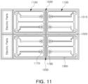
- FIG. 11 illustrates the battery pack of FIG. 10 viewed from above.
- a battery pack 1000 based on an embodiment of the disclosed technology may include a plurality of battery modules 1100 based on an embodiment of the disclosed technology described above.
- a plurality of battery modules 1100 based on an embodiment of the disclosed technology may be accommodated in a pack housing 1010.
- the plurality of battery modules 1100 may be accommodated in an internal space provided in the pack housing 1010.
- the internal space of the pack housing 1010 may be divided into a plurality of spaces by a center beam 1020 extending in a longitudinal direction of the pack housing 1010 and a cross beam 1030 extending in a width direction of the pack housing 1010, and the plurality of battery modules 1100 may be disposed in the plurality of partitioned spaces, respectively.
- a space in which electric parts are disposed may be separately provided on one side of the pack housing 1010.
- the internal space of the pack housing 1010 may be partitioned into a plurality of spaces in a longitudinal direction and a width direction thereof by the center beam 1020 and the cross beam 1030, and the plurality of battery modules 1100 may be respectively disposed in a plurality of partitioned spaces.
- a gap may be formed between the plurality of battery modules 1100 and the center beam 1020 and the cross beam 1030 respectively disposed in the plurality of partitioned spaces.
- the plurality of battery modules 1100 may be disposed to be spaced apart from the center beam 1020 and the cross beam 1030, and accordingly, an air gap may be formed between the plurality of battery modules 1100 and the center beam 1020 and the cross beam 1030.
- the air gap may confine heat generated from the battery module 1100 in a partitioned space where the battery module 1100 is disposed and delay propagation of heat to adjacent battery modules 1100.
- the plurality of battery modules 1100 may be disposed so that an inlet 1160 and an outlet 1170 provided in each of the battery modules 1100 are placed on a side of the cross beam 1030 side, as will be discussed below.
- a pack cover 1040 may be disposed on an upper side of the pack housing 1010 to cover an internal space.
- the pack cover 1040 may seal the internal space to protect various parts disposed in the internal space including a plurality of battery modules 1100.
- the inlet 1160 and outlet 1170 of the battery module 1100 may be exposed externally of the pack cover 1040.
- the pack cover 1040 may include a plurality of holes 1041, and one end of the inlet 1160 and the outlet 1170 may be exposed externally of the pack cover 1040 through the plurality of holes 1041.
- a pipe joint 1180 may be coupled to one end of the inlet 1160 and the outlet 1170 exposed through the hole 1041 of the pack cover 1040.
- an external hose may be coupled to the pipe joint 1180.
- the inlet 1160 and the outlet 1170 may be connected to an external hose through the pipe joint 1180.
- the pipe joint 1180 may connect the inlet 1160 and the outlet 1170 with an external hose, and serve to seal the same.
- the plurality of battery modules 1100 may include an inlet 1160 and an outlet 1170 on one side of the plurality of battery cells 1110 constituting each battery module 1100 in the stacking direction, and the plurality of battery modules 1100 may be accommodated in the pack housing 1010 so that one side thereof including an inlet 1160 and an outlet 1170 is close to each other between battery modules 1100, disposed adjacent to each other.
- the battery module 1100 may be disposed so that the inlet 1160 and the outlet 1170 are placed toward a central portion of the pack housing 1010.
- a plurality of battery modules 1100 may be accommodated in a pack housing 1010 so that an inlet 1160 and an outlet 1170 face a side of the cross beam 1030.
- the plurality of battery modules 1100 may also be disposed so that the inlet 1160 and the outlet 1170 face a side of the center beam 1020.
- connection between the plurality of battery modules 1100 and ports is collectively performed in the central portion of the pack housing 1010, a shape of and connection structure of a piping (external hose) may be simplified.
- an arrangement form of the plurality of battery modules 1100 may also be changed.
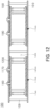
- FIG. 12 is a schematic diagram of a battery pack based on another embodiment of the disclosed technology
- FIG. 13 is a conceptual diagram for illustrating a thermal blocking effect of the battery pack of FIG. 12 .
- a battery pack 1000 based on an embodiment of the disclosed technology may further include a heat insulation member 1200 between the battery module 1100 and the battery pack 1000.
- the heat insulation member 1200 may be disposed between an upper cooling plate 1130 and a pack cover 1040 and between a lower cooling plate 1140 and a pack housing 1010.
- the pack housing 1010 and the pack cover 1040, shared by the plurality of battery modules 1100 constituting the battery pack 1000 may be formed of a metal material having high thermal conductivity, for example, an aluminum material, and accordingly, when the pack housing 1010 and the pack cover 1040 directly face the upper cooling plate 1130 and the lower cooling plate 1140 of the battery module 1100, heat transfer to the battery module 1100 disposed adjacent to the pack housing 1010 may be facilitated. Therefore, in another embodiment of the disclosed technology, as shown in FIG. 13 , propagation of heat between the battery modules 1100 may be prevented or delayed by additionally disposing the heat insulation member 1200 on a heat transfer path.
- the heat insulation member 1200 may be formed of a heat-resistant material, and for example, the heat insulation member 200 may be formed of a material such as mica or ceramic wool. Since these materials do not melt at a temperature at which the battery cell 1110 is ignited, structural collapse of the battery pack 1000 due to occurrence of an event may be prevented.
- cooling performance and efficiency may be increased.
- overall cooling performance and efficiency may be improved, and propagation of heat to adjacent battery modules 100 may be minimized. Accordingly, the disclosed technology can be implemented in some implements to provide a thermally stable battery pack 1000.
- the disclosed technology can be implemented in some embodiments a battery module and a battery pack including the battery module with improved cooling performance and efficiency.
- the battery pack based on an embodiment of the disclosed technology may prevent or delay propagation of heat to adjacent battery modules.
- the disclosed technology can be implemented in rechargeable secondary batteries and modules of rechargeable secondary batteries that are widely used in battery-powered devices or systems, including, e.g., digital cameras, mobile phones, notebook computers, hybrid vehicles, electric vehicles, uninterruptible power supplies, battery storage power stations, and others including battery power storage for solar panels, wind power generators and other green tech power generators.
- the disclosed technology can be implemented in some embodiments to provide improved electrochemical devices such as a battery used in various power sources and power supplies, thereby mitigating climate changes in connection with uses of power sources and power supplies.
- Lithium secondary batteries based on the disclosed technology can be used to address various adverse effects such as air pollution and greenhouse emissions by powering electric vehicles (EVs) as alternatives to vehicles using fossil fuel-based engines and by providing battery-based energy storage systems (ESSs) to store renewable energy such as solar power and wind power.
- EVs electric vehicles
- ESSs battery-based energy storage systems
Landscapes
- Chemical & Material Sciences (AREA)
- Chemical Kinetics & Catalysis (AREA)
- Electrochemistry (AREA)
- General Chemical & Material Sciences (AREA)
- Engineering & Computer Science (AREA)
- Manufacturing & Machinery (AREA)
- Secondary Cells (AREA)
- Battery Mounting, Suspending (AREA)
Abstract
Description
- The technology and implementations disclosed in this patent document generally relate to a battery module and a battery pack including the same.
- Secondary batteries can charge and discharge repeatedly because of the reversible mutual conversion between chemical energy and electrical energy.
- Secondary batteries may be used as an energy source for electric vehicles, hybrid vehicles, energy storage systems (ESSs), and mobile devices.
- An aspect of the disclosed technology is to provide a battery module having improved cooling performance and efficiency and a battery pack including the same.
- An aspect of the disclosed technology is to provide a battery pack preventing or delaying propagation of heat between battery modules.
- In an aspect of the disclosed technology, a battery module, may include: a plurality of battery cells arranged in a row one direction; an end plate disposed adjacent to an outermost battery cell of the plurality of battery cells; and an upper cooling plate and a lower cooling plate disposed above and below the plurality of battery cells, respectively, and structured to include a first cooling flow path and a second cooling flow path , respectively, for a coolant for cooling the plurality of battery cells to flow, wherein the end plate may include a flow path connection portion connected between the upper cooling plate and the lower cooling plate for the coolant to flow between the first cooling flow path and the second cooling flow path.
- In an embodiment of the disclosed technology, the battery module, may further include: an inlet connected to at least one of the first cooling flow path, the second cooling flow path, or the at least one flow path connection portion to supply the coolant into the first and second cooling flow paths and the at least one flow path connection portion, and an outlet to at least one of the first cooling flow path, the second cooling flow path, or the at least one flow path connection portion to discharge the coolant from the first and second cooling flow paths and the at least one flow path connection portion.
- In an aspect of the disclosed technology, the inlet and the outlet may be disposed on at least one of the upper cooling plate and the lower cooling plate.
- In an aspect of the disclosed technology, the flow path connection portion may include a pair of flow path connection portions disposed to be spaced apart from each other the one direction of the plurality of battery cells.
- In an aspect of the disclosed technology, the upper cooling plate or the lower cooling plate including the inlet and the outlet may include a first portion including a cooling flow path connected to the inlet, and a second portion including a cooling flow path connected to the outlet, wherein the first portion and the second portion may be separated and spaced apart from each other on the upper cooling plate or the lower cooling plate.
- In an aspect of the disclosed technology, the second portion may have an area at least the same as or greater than that of the first portion.
- In an aspect of the disclosed technology, one of the first cooling flow path or the second cooling flow path may not include the inlet and the outlet, wherein all parts of the one of the first cooling flow path or the second cooling flow path may be coupled to each other.
- In an aspect of the disclosed technology, wherein the pair of flow path connection portions may include a first flow path connection portion and a second flow path connection portion, wherein the first flow path connection portion may be structured to allow the coolant to flow from the upper cooling plate to the lower cooling plate, and the second flow path connection portion may be structured to allow the coolant to flow from the lower cooling plate to the upper cooling plate.
- In an aspect of the disclosed technology, the battery module, may further include: a heat dissipation member disposed between the plurality of battery cells and the upper cooling plate and the lower cooling plate may be further included.
- In an aspect of the disclosed technology, the plurality of battery cells may include prismatic battery cells each of which includes an electrode terminals on both sides of each of the plurality of battery cells.
- In an aspect of the disclosed technology, a battery pack, may include: a plurality of battery modules of any one of described above; a pack housing structured to accommodate the battery module; and a pack cover coupled to the pack housing to cover the battery module.
- In an aspect of the disclosed technology, the inlet and the outlet may be exposed externally through the pack cover, and may further include a pipe joint coupled to the inlet and the outlet exposed through the pack cover, wherein the battery pack, may further include: a pipe joint coupled to the inlet and the outlet exposed through the pack cover.
- In an aspect of the disclosed technology, the inlet and the outlet may be arranged on one side of the battery module, wherein the plurality of battery modules may be accommodated in the pack housing, and the inlet and the outlet may be disposed close to each other between battery modules.
- In an aspect of the disclosed technology, wherein a side surface of the battery module may be spaced apart from the pack housing, and an air gap may be formed between the battery module and the pack housing.
- In an aspect of the disclosed technology, the battery pack, may further include: a heat insulation member disposed on at least one of a space between the battery module and the pack housing or a space between the battery module and the pack cover may be further included.
-
-
FIG. 1 illustrates a cooling structure of an example battery pack. -
FIG. 2 illustrates an example cooling plate ofFIG. 1 . -
FIG. 3 is a schematic perspective view of a battery module based on an embodiment of the disclosed technology. -
FIG. 4 is an example side view of the battery module ofFIG. 3 . -
FIG. 5 is another example side view of the battery module ofFIG. 3 . -
FIGS. 6 illustrates an example configuration of cooling flow paths of upper and lower cooling plates based on some embodiments of the disclosed technology. -
FIG. 7 illustrates another example configuration of cooling flow paths of upper and lower cooling plates based on some embodiments of the disclosed technology. -
FIG. 8 illustrates another example configuration of cooling flow paths of upper and lower cooling plates based on some embodiments of the disclosed technology. -
FIG. 9 illustrates another example configuration of cooling flow paths of upper and lower cooling plates based on some embodiments of the disclosed technology. -
FIG. 10 is a schematic diagram of a battery pack based on an embodiment of the disclosed technology. -
FIG. 11 illustrates the battery pack ofFIG. 10 viewed from above. -
FIG. 12 is a schematic diagram of a battery pack based on another embodiment of the disclosed technology. -
FIG. 13 is a conceptual diagram illustrating a heat blocking effect of the battery pack ofFIG. 12 . - Secondary batteries are widely used in various applications in part because they can be recharged and may be configured in various configurations with battery cells in various forms such as flexible pouch-type battery cells, or prismatic or cylindrical can-type rigid battery cells. Those battery cells are electrically connected in ways to provide desired electrical power output. Electric vehicles requiring high power may use a battery module that includes one or more cell stacks, each of which includes a plurality of battery cells stacked and electrically connected, or may use a battery pack that includes one or more battery modules that are electrically connected.
- The performance of secondary batteries may be affected by temperature. In particular, when the temperature of secondary batteries is higher than a proper temperature, the performance of secondary batteries is degraded, and in severe cases, the increase in the temperature of secondary batteries may lead to explosion and ignition. Battery modules including a plurality of battery cells or battery packs including a plurality of battery modules may increase the risk of explosion and ignition. The disclosed technology can be implemented in some embodiments to provide battery module and battery pack structures that can control heat generated in the battery cells.
-
FIG. 1 illustrates a cooling structure of an example battery pack, andFIG. 2 illustrates an example cooling plate ofFIG. 1 . - Referring to
FIG. 1 , in anexample battery pack 1, a plurality ofbattery modules 10 can be cooled by using acooling plate 20 disposed below the plurality ofbattery modules 10 constituting thebattery pack 1. However, this structure may have limitations in improving cooling performance and efficiency because cooling is performed only on one side of thebattery module 10. In addition, as shown inFIG. 2 , since the plurality ofbattery modules 10 shares thecooling plate 20, heat transfer between adjacent modules may cause thermal runaway. - The disclosed technology can be implemented in some embodiments to provide a
battery module 100 and abattery pack 1000 including thebattery module 100 to perform cooling is performed on both surfaces of thebattery module 100 and/or thebattery pack 1000. - The disclosed technology can be implemented in some embodiments to provide a battery module as will be described with reference to
FIGS. 3 to 9 . -
FIG. 3 is a schematic perspective view of a battery module based on an embodiment of the disclosed technology.FIGS. 4 and 5 are example side views of the battery module ofFIG. 3 . - In some implementations, a
battery module 100 based on an embodiment of the disclosed technology may include a plurality ofbattery cells 110 and a plurality ofcooling plates battery cells 110. - In an embodiment of the disclosed technology, the plurality of
battery cells 110 may be prismatic battery cells. In some implementations, the prismatic battery cell may include acase 111 structured to accommodate an electrode assembly and an electrolyte. In one example, thecase 111 may have a flat and angular shape. In some implementations, thecase 111 of the prismatic battery cell may include an aluminum material. - In an embodiment of the disclosed technology, the plurality of
battery cells 110 may have a shape in which electrode terminals protrude on both sides in a longitudinal direction. For example, apositive terminal 112 may be formed to protrude on one side of the plurality ofbattery cells 110 in the longitudinal direction, and anegative terminal 113 may be formed to protrude on the other side of the plurality ofbattery cells 110. The plurality ofbattery cells 110 may be electrically connected to the outside through electrode terminals. - In an embodiment of the disclosed technology, the plurality of
battery cells 110 may be arranged in a row in one direction. In an implementation, the plurality ofbattery cells 110 may be stacked in one direction. For example, the plurality ofbattery cells 110 may be arranged or stacked such that a wide surface of thecase 111 face each other. In one example, the plurality ofbattery cells 110 may be arranged or stacked such that positive terminals and negative terminals are alternately disposed in a stacking direction as shown inFIG. 3 . - In some implementation, a compression member (not shown) may be disposed between the plurality of
battery cells 110 to fill a gap between the plurality ofbattery cells 110. For example, the compression member may be formed of a polyurethane material. - The
battery module 100 based on an embodiment of the disclosed technology may include anend plate 120 disposed on an outermost side of the plurality ofbattery cells 110 in a stacking direction. Theend plate 120 may be disposed on both sides of the plurality ofbattery cells 110 in the stacking direction. Theend plate 120 may fix and support the plurality ofbattery cells 110 in the stacking direction of the plurality ofbattery cells 110. - Since the
end plate 120 forms an exterior of thebattery module 100, theend plate 120 should have structural rigidity, and at the same time, theend plate 120 should be able to prevent electrical short circuits caused by contact with the plurality ofbattery cells 110 and to absorb shocks. For example, theend plate 120 may include a metal material and an insulating material, and a portion of the metal material and a portion of the insulating material may be integrally formed or separately formed. - In some implementations, although not illustrated in the drawings, a side plate (not shown) may be disposed on both sides of the plurality of
battery cells 110 in a longitudinal direction, respectively. - The
battery module 100 based on an embodiment of the disclosed technology may include a plurality of coolingplates battery cells 110. In an embodiment of the disclosed technology, the plurality of coolingplates battery cells 110, and thus, cooling (e.g., thermal management) may be performed on both surfaces of the plurality ofbattery cells 110. The plurality of coolingplates plates battery cells 110 is referred to as anupper cooling plate 130, and a cooling plate disposed below the plurality ofbattery cells 110 is referred to as alower cooling plate 140. - In an embodiment of the disclosed technology, the
upper cooling plate 130 and thelower cooling plate 140 may be disposed to cover upper and lower portions of the plurality ofbattery cells 110, respectively. In some implementations, theupper cooling plate 130 and thelower cooling plate 140 may directly face the upper and lower portions of the plurality ofbattery cells 110, respectively. In one example, a heat dissipation member (not shown) may be additionally disposed between the plurality ofbattery cells 110 and theupper cooling plate 130 and thelower cooling plate 140. For example, the heat dissipation member may be provided with a thermal pad or thermal paste. The heat dissipation member may contribute to improving cooling performance and efficiency of thebattery module 100 by filling a minute gap that may exist between the plurality ofbattery cells 110 and theupper cooling plate 130 and thelower cooling plate 140. - The
upper cooling plate 130 and thelower cooling plate 140 may include a cooling flow path (hereinafter, an upper cooling flow path 131 and a lower cooling flow path 141) through which a coolant such as cooling water for cooling the plurality ofbattery cells 110, flows. The upper cooling flow path 131 and the lowercooling flow path 141 may be formed on a whole surface of theupper cooling plate 130 and thelower cooling plate 140 so that heat exchange can be sufficiently performed on both surfaces of the plurality ofbattery cells 110. - In an embodiment of the disclosed technology, the upper cooling flow path 131 and the lower
cooling flow path 141 may be connected to each other. To this end, thebattery module 100 based on an embodiment of the disclosed technology may include a flowpath connection portion 150 connecting the upper cooling flow path 131 and the lowercooling flow path 141. - In an embodiment, the flow
path connection portion 150 may be disposed on theend plate 120. The flowpath connection portion 150 may extend in a height direction of theend plate 120, so that one side of the flowpath connection portion 150 may be connected to theupper cooling plate 130, and the other side thereof may be connected to thelower cooling plate 140. In some implementations, the flowpath connection portion 150 may include aconnection pipe 151, one side of theconnection pipe 151 may communicate with the upper cooling passage 131 and the other side communicate with the lowercooling flow path 141, so that cooling water may flow from thecooling plate 130 to thelower cooling plate 140 and/or vice versa. - In addition, in some implementations, the flow
path connection portion 150 may further include arubber hose 152 surrounding theconnection pipe 151 and aclamp 153 fixing therubber hose 152. Therubber horse 152 may be provided to surround substantially an entirety of theconnection pipe 151, and theclamp 153 may be inserted into both ends of therubber hose 152 to fix therubber hose 152 to theconnection pipe 151. - In an embodiment of the disclosed technology, a pair of flow
path connection portions 150 may be provided. In other words, thebattery module 100 based on an embodiment of the disclosed technology may include a pair of flowpath connection portions 150. The pair of flowpath connection portions 150 may be disposed to be spaced apart from each other in a longitudinal direction of the plurality ofbattery cells 110. In some implementations, the pair of flowpath connection portions 150 may be disposed to be spaced apart from the outside of theend plate 120 in the longitudinal direction of the plurality ofbattery cells 110 on the outside of theend plate 120 in a stacking direction of the plurality ofbattery cells 110. - In an embodiment of the disclosed technology, the pair of flow
path connection portions 150 may be disposed to provide a flow of coolant such as cooling water from a direction of theupper cooling plate 130 to a direction of thelower cooling plate 140 and/or in an opposite direction thereof. Therefore, as will be described later, in an embodiment in which theupper cooling plate 130 and thelower cooling plate 140 include any one of theinlet 160 and theoutlet 170, respectively, the flowpath connection portions 150 are not necessarily provided in a pair. - The
battery module 100 based on an embodiment of the disclosed technology may include aninlet 160 supplying cooling water to theupper cooling plate 130 or thelower cooling plate 140, and anoutlet 170 discharging cooling water externally of thebattery module 100. That is, theinlet 160 and theoutlet 170 may communicate withcooling flow paths 131 and 141 of the coolingplates - In an embodiment, the
inlet 160 and theoutlet 170 may be disposed together on theupper cooling plate 130 or thelower cooling plate 140. In the drawings, it is illustrated that theinlet 160 and theoutlet 170 are disposed on theupper cooling plate 130, but as described above, theinlet 160 and theoutlet 170 may be disposed on thelower cooling plate 140 instead of theupper cooling plate 130. In addition, in another embodiment, theinlet 160 and theoutlet 170 may be separately disposed on theupper cooling plate 130 and thelower cooling plate 140. That is, theinlet 160 may be disposed on theupper cooling plate 130 and theoutlet 170 may be disposed on thelower cooling plate 140. Conversely, in some implementations, theinlet 160 may be disposed on thelower cooling plate 140 and theoutlet 170 may be disposed on theupper cooling plate 130. - In some embodiments of the disclosed technology, the
battery module 100 may include aninlet 160 and anoutlet 170, and a position in which theinlet 160 and theoutlet 170 are disposed is not particularly limited. However, by way of example only, an embodiment in which both theinlet 160 and theoutlet 170 are in theupper cooling plate 130 will be explained. - In an embodiment of the disclosed technology, the
inlet 160 and theoutlet 170 may be disposed to be spaced apart from the pair of flowpath connection portions 150 in a direction in which the plurality ofbattery cells 110 are arranged or stacked. Furthermore, cooling flow paths131 and 141 may be formed between theinlet 160 and theoutlet 170 and the pair ofpassage connection portions 150. - In an embodiment of the disclosed technology, a coolant such as cooling water may flow into an upper cooling flow path 131 through the
inlet 160, may pass through a lowercooling flow path 141, and may be discharged externally through theoutlet 170 connected to the upper cooling flow path 131. Cooling water may flow between the upper cooling flow path 131 and the lowercooling flow path 141 by the flowpath connection portion 150. - The cooling water may flow in one direction along the
cooling flow path 131 and 141 formed in the coolingplates cooling flow paths 131 and 141 may be continuously formed between theinlet 160 and theoutlet 170, and the upper cooling flow path and the lowercooling flow path 141 may communicate with each other through aconnection pipe 151. For example, in an embodiment in which theinlet 160 and theoutlet 170 are both disposed on theupper cooling plate 130, the cooling water flowing into theinlet 160 may flow from the upper cooling flow path 131 to the lowercooling flow path 141 through one of a pair of flowpath connection portions 150, and may flow from the lowercooling flow path 141 to the upper cooling flow path 131 through the other thereof and may be discharged through theoutlet 170. - In order to provide a path through which a coolant such as cooling water flows described above, the upper cooling flow path 131 may include a
first portion 131a and asecond portion 131b that are separated or not connected to each other on theupper cooling plate 130. For example, the cooling water cannot directly flow from thefirst portion 131a to thesecond portion 131b, and can flow into thesecond portion 131b only through a lowercooling flow path 141. The lowercooling flow path 141 may be continuously formed on thelower cooling plate 140. - In an embodiment of the disclosed technology, one side of the
first portion 131a may be connected to theinlet 160 and the other side may be connected to the flowpath connection portion 150, and one side of thesecond portion 131b may be connected to theoutlet 170, and the other side thereof may be connected to the is connected to and the other side may be connected to the flowpath connection portion 150. In this case, thefirst portion 131a and thesecond portion 131b may be connected to different flowpath connection portions 150. Also, one side and the other side of the lowercooling flow path 141 may be connected to a pair of flowpath connection portions 150. -
FIGS. 6 to 9 illustrate example configurations of cooling flow paths of upper and lower cooling plates based on various embodiments of the disclosed technology. - Referring to
FIGS. 6 to 9 , an upper cooling flow path 131 and a lowercooling flow path 141 may be provided in various forms in anupper cooling plate 130 and alower cooling plate 140. - Referring to
FIG. 6 , afirst portion 131a and asecond portion 131b of the upper cooling flow path 131 may have the same or substantially the same area. A coolant such as cooling water may cool the plurality ofbattery cells 110 while flowing along thefirst portion 131a of the upper cooling flow path 131. In an embodiment, referring toFIG. 6 , the cooling water flowing into theinlet 160 may cool a side of upper surfaces of the plurality ofbattery cells 110 and then moved to thelower cooling plate 140, and such a cooling operation may be evenly performed on the upper and lower surfaces of thebattery cells 110. - Referring to
FIGS. 7 and8 , the upper cooling flow path 131 may be mainly provided in thesecond portion 131b. In the embodiments ofFIGS. 7 and8 , the coolant such as cooling water flowing into theinlet 160 may directly flow to the lowercooling flow path 141 through the flowpath connection portion 150 without exchanging heat with the plurality ofbattery cells 110. In an embodiment, cooling may be mainly performed in lower portions of the plurality ofbattery cells 110. However, as shown inFIG. 8 , when thefirst portion 131a is provided so that cooling water faces the flowpath connection portion 150 disposed in a direction that is diagonal to theinlet 160, the cooling water may flow through the shortest path in thesecond portion 131b. - Different from
FIG. 6 ,FIG. 9 illustrates an example configuration of a cooling flow path in a case in which theinlet 160 and theoutlet 170 are disposed diagonally on theupper cooling plate 130. - In some implementations, a temperature of the coolant such as cooling water may increase in a process of flowing through
cooling flow paths 131 and 141 and exchanging heat with the plurality ofbattery cells 110. Accordingly, the temperature of the coolant (e.g., cooling water) discharged through theoutlet 170 may be higher than the temperature of the coolant (e.g., cooling water) flowing into theinlet 160. - In an embodiment of the disclosed technology, the
inlet 160 and the outlets170 may be formed to protrude from theupper cooling plate 130 and/or thelower cooling plate 140 in a height direction of the plurality ofbattery cells 110. Furthermore, theinlet 160 and theoutlet 170 may be exposed through apack cover 1040 of abattery pack 1000, as will be discussed below, and a pipe joint 1180 may be coupled to theinlet 160 and theoutlet 170. - The disclosed technology can be implemented in some embodiments to provide a battery pack as will be discussed below with reference to
FIGS. 10 to 13 . -
FIG. 10 is a schematic diagram of a battery pack based on an embodiment of the disclosed technologyFIG. 11 illustrates the battery pack ofFIG. 10 viewed from above. - Referring to the drawings, a
battery pack 1000 based on an embodiment of the disclosed technology may include a plurality ofbattery modules 1100 based on an embodiment of the disclosed technology described above. - A plurality of
battery modules 1100 based on an embodiment of the disclosed technology may be accommodated in apack housing 1010. In detail, the plurality ofbattery modules 1100 may be accommodated in an internal space provided in thepack housing 1010. Referring toFIG. 11 , the internal space of thepack housing 1010 may be divided into a plurality of spaces by acenter beam 1020 extending in a longitudinal direction of thepack housing 1010 and across beam 1030 extending in a width direction of thepack housing 1010, and the plurality ofbattery modules 1100 may be disposed in the plurality of partitioned spaces, respectively. In addition, a space in which electric parts are disposed may be separately provided on one side of thepack housing 1010. - In an embodiment of the disclosed technology, as described above, the internal space of the
pack housing 1010 may be partitioned into a plurality of spaces in a longitudinal direction and a width direction thereof by thecenter beam 1020 and thecross beam 1030, and the plurality ofbattery modules 1100 may be respectively disposed in a plurality of partitioned spaces. In this case, a gap may be formed between the plurality ofbattery modules 1100 and thecenter beam 1020 and thecross beam 1030 respectively disposed in the plurality of partitioned spaces. In other words, the plurality ofbattery modules 1100 may be disposed to be spaced apart from thecenter beam 1020 and thecross beam 1030, and accordingly, an air gap may be formed between the plurality ofbattery modules 1100 and thecenter beam 1020 and thecross beam 1030. The air gap may confine heat generated from thebattery module 1100 in a partitioned space where thebattery module 1100 is disposed and delay propagation of heat toadjacent battery modules 1100. - In addition, in an embodiment of the disclosed technology, the plurality of
battery modules 1100 may be disposed so that aninlet 1160 and anoutlet 1170 provided in each of thebattery modules 1100 are placed on a side of thecross beam 1030 side, as will be discussed below. - In an embodiment of the disclosure, a
pack cover 1040 may be disposed on an upper side of thepack housing 1010 to cover an internal space. Thepack cover 1040 may seal the internal space to protect various parts disposed in the internal space including a plurality ofbattery modules 1100. - In an embodiment of the disclosed technology, the
inlet 1160 andoutlet 1170 of thebattery module 1100 may be exposed externally of thepack cover 1040. For example, thepack cover 1040 may include a plurality of holes 1041, and one end of theinlet 1160 and theoutlet 1170 may be exposed externally of thepack cover 1040 through the plurality of holes 1041. - A pipe joint 1180 may be coupled to one end of the
inlet 1160 and theoutlet 1170 exposed through the hole 1041 of thepack cover 1040. In addition, an external hose may be coupled to the pipe joint 1180. Accordingly, theinlet 1160 and theoutlet 1170 may be connected to an external hose through the pipe joint 1180. The pipe joint 1180 may connect theinlet 1160 and theoutlet 1170 with an external hose, and serve to seal the same. - In an embodiment of the disclosed technology, the plurality of
battery modules 1100 may include aninlet 1160 and anoutlet 1170 on one side of the plurality of battery cells 1110 constituting eachbattery module 1100 in the stacking direction, and the plurality ofbattery modules 1100 may be accommodated in thepack housing 1010 so that one side thereof including aninlet 1160 and anoutlet 1170 is close to each other betweenbattery modules 1100, disposed adjacent to each other. - For example, the
battery module 1100 may be disposed so that theinlet 1160 and theoutlet 1170 are placed toward a central portion of thepack housing 1010. Referring to the drawing, a plurality ofbattery modules 1100 may be accommodated in apack housing 1010 so that aninlet 1160 and anoutlet 1170 face a side of thecross beam 1030. However, in another embodiment, the plurality ofbattery modules 1100 may also be disposed so that theinlet 1160 and theoutlet 1170 face a side of thecenter beam 1020. When the plurality ofbattery modules 1100 are disposed in this manner, since connection between the plurality ofbattery modules 1100 and ports is collectively performed in the central portion of thepack housing 1010, a shape of and connection structure of a piping (external hose) may be simplified. - Unlike the above-described embodiment, when the positions of the
inlet 1160 and theoutlet 1170 provided in each of thebattery modules 1100 are changed, an arrangement form of the plurality ofbattery modules 1100 may also be changed. -
FIG. 12 is a schematic diagram of a battery pack based on another embodiment of the disclosed technology, andFIG. 13 is a conceptual diagram for illustrating a thermal blocking effect of the battery pack ofFIG. 12 . - As shown in
FIG. 12 , abattery pack 1000 based on an embodiment of the disclosed technology may further include aheat insulation member 1200 between thebattery module 1100 and thebattery pack 1000. In an embodiment of the disclosed technology, theheat insulation member 1200 may be disposed between an upper cooling plate 1130 and apack cover 1040 and between a lower cooling plate 1140 and apack housing 1010. - In an embodiment of the disclosed technology, the
pack housing 1010 and thepack cover 1040, shared by the plurality ofbattery modules 1100 constituting thebattery pack 1000 may be formed of a metal material having high thermal conductivity, for example, an aluminum material, and accordingly, when thepack housing 1010 and thepack cover 1040 directly face the upper cooling plate 1130 and the lower cooling plate 1140 of thebattery module 1100, heat transfer to thebattery module 1100 disposed adjacent to thepack housing 1010 may be facilitated. Therefore, in another embodiment of the disclosed technology, as shown inFIG. 13 , propagation of heat between thebattery modules 1100 may be prevented or delayed by additionally disposing theheat insulation member 1200 on a heat transfer path. - The
heat insulation member 1200 may be formed of a heat-resistant material, and for example, the heat insulation member 200 may be formed of a material such as mica or ceramic wool. Since these materials do not melt at a temperature at which the battery cell 1110 is ignited, structural collapse of thebattery pack 1000 due to occurrence of an event may be prevented. - As described above, since cooling is performed on the plurality of
battery cells 110 above and below thebattery module 100 based on an embodiment of the disclosed technology, cooling performance and efficiency may be increased. In addition, since cooling is performed independently for eachbattery module 100 on a side surface of thebattery pack 1000, overall cooling performance and efficiency may be improved, and propagation of heat toadjacent battery modules 100 may be minimized. Accordingly, the disclosed technology can be implemented in some implements to provide a thermallystable battery pack 1000. - As set forth above, in an embodiment of the disclosed technology, the disclosed technology can be implemented in some embodiments a battery module and a battery pack including the battery module with improved cooling performance and efficiency.
- In addition, the battery pack based on an embodiment of the disclosed technology may prevent or delay propagation of heat to adjacent battery modules.
- The disclosed technology can be implemented in rechargeable secondary batteries and modules of rechargeable secondary batteries that are widely used in battery-powered devices or systems, including, e.g., digital cameras, mobile phones, notebook computers, hybrid vehicles, electric vehicles, uninterruptible power supplies, battery storage power stations, and others including battery power storage for solar panels, wind power generators and other green tech power generators. Specifically, the disclosed technology can be implemented in some embodiments to provide improved electrochemical devices such as a battery used in various power sources and power supplies, thereby mitigating climate changes in connection with uses of power sources and power supplies. Lithium secondary batteries based on the disclosed technology can be used to address various adverse effects such as air pollution and greenhouse emissions by powering electric vehicles (EVs) as alternatives to vehicles using fossil fuel-based engines and by providing battery-based energy storage systems (ESSs) to store renewable energy such as solar power and wind power.
Claims (15)
- A battery module (100), comprising:a plurality of battery cells (110) arranged in a row one direction;an end plate (120) disposed adjacent to an outermost battery cell of the plurality of battery cells; andan upper cooling plate (130) and a lower cooling plate (140) disposed above and below the plurality of battery cells (110), respectively, and structured to include a first cooling flow path (131) and a second cooling flow path (141), respectively, for a coolant for cooling the plurality of battery cells (110) to flow,wherein the end plate (120) includes at least one flow path connection portion (150) connected between the upper cooling plate (130) and the lower cooling plate (140) for the coolant to flow between the first cooling flow path (131) and the second cooling flow path (141).
- The battery module (100) of claim 1, further comprising:
an inlet (160) connected to at least one of the first cooling flow path(131), the second cooling flow path (141), or the at least one flow path connection portion (150) to supply the coolant into the first and second cooling flow paths (131, 141) and the at least one flow path connection portion (150), and an outlet (170) to at least one of the first cooling flow path (131), the second cooling flow path (141), or the at least one flow path connection portion (150) to discharge the coolant from the first and second cooling flow paths (131, 141) and the at least one flow path connection portion (150). - The battery module (100) of claim 2, wherein the inlet (160) and the outlet (170) are disposed on at least one of the upper cooling plate (130) or the lower cooling plate (140).
- The battery module (100) of anyone of claims 1 to 3, wherein the flow path connection portion (150) includes a pair of flow path connection portions (150), disposed to be spaced apart from each other the one direction of the plurality of battery cells (110).
- The battery module (100) of anyone of claims 2 to 4, wherein the upper cooling plate (130) or the lower cooling plate (140) including the inlet (160) and the outlet (170) comprises a first portion (131a) including a cooling flow path (131) connected to the inlet (160) and a second portion (131b) including a cooling flow path (131) connected to the outlet (170), and
the first portion (131a) and the second portion (131b) are separated and spaced apart from each other on the upper cooling plate (130) or the lower cooling plate (140). - The battery module (100) of claim 5, wherein the second portion (131b) is formed to have the same area as the first portion (131a) or to have a greater area than the first portion (131a).
- The battery module (100) of anyone of claims 2 to 6, wherein one of the first cooling flow path (131) or the second cooling flow path (141) does not include the inlet (160) and the outlet (170), wherein all parts of the one of the first cooling flow path (131) or the second flow path (141) are coupled to each other.
- The battery module (100) of anyone of claims 4 to 7, wherein the pair of flow path connection portions (150) includes a first flow path connection portion and a second flow path connection portion, wherein the first flow path connection portion is structured to allow the coolant to flow from the upper cooling plate (130) to the lower cooling plate (140), and the second flow path connection portion is structured to allow the coolant to flow from the lower cooling plate (140) to the upper cooling plate (130).
- The battery module (100) of anyone of claims 1 to 8, further comprising:
a heat dissipation member disposed between the plurality of battery cells (110) and the upper cooling plate (130) and the lower cooling plate (140). - The battery module (100) of anyone of claims 1 to 9, wherein the plurality of battery cells (110) includes prismatic battery cells each of which includes electrode terminals on both sides of each of the plurality of battery cells (110).
- A battery pack (1000), comprising:the plurality of battery modules (1100) of any one of claims 1 to 10;a pack housing (1010) structured to accommodate the battery module (1100); anda pack cover (1040) coupled to the pack housing (1010) to cover the battery module (1100).
- The battery pack (1000) of claim 11, wherein the inlet (1160) and the outlet (1170) are exposed externally through the pack cover (1040),
wherein the battery pack (1000), further comprises:
a pipe joint (1180) coupled to the inlet (1160) and the outlet (1170) exposed through the pack cover (1040). - The battery pack (1000) of claim 11 or 12, wherein the inlet (1160) and the outlet (1170) are arranged on one side of the battery module (1100),
wherein the plurality of battery modules (1100) is accommodated in the pack housing (1010), and the inlet (1160) and the outlet (1170) are disposed close to each other between battery modules (1100). - The battery pack (1000) of anyone of claims 11 to 13, wherein a side surface of the battery module (1100) is spaced apart from the pack housing (1010), and an air gap is formed between the battery module (1100) and the pack housing (1010) .
- The battery pack (1000) of anyone of claims 11 to 14, further comprising:
a heat insulation member disposed on at least one of a space between the battery module (1100) and the pack housing (1010) or a space between the battery module (1100) and the pack cover (1040).
Applications Claiming Priority (1)
| Application Number | Priority Date | Filing Date | Title |
|---|---|---|---|
| KR1020220169297A KR20240084709A (en) | 2022-12-07 | 2022-12-07 | Battery module and Battery pack including the same |
Publications (1)
| Publication Number | Publication Date |
|---|---|
| EP4401180A1 true EP4401180A1 (en) | 2024-07-17 |
Family
ID=88833670
Family Applications (1)
| Application Number | Title | Priority Date | Filing Date |
|---|---|---|---|
| EP23209718.8A Pending EP4401180A1 (en) | 2022-12-07 | 2023-11-14 | Battery module and battery pack including the same |
Country Status (4)
| Country | Link |
|---|---|
| US (1) | US20240194964A1 (en) |
| EP (1) | EP4401180A1 (en) |
| KR (1) | KR20240084709A (en) |
| CN (1) | CN118156666A (en) |
Citations (4)
| Publication number | Priority date | Publication date | Assignee | Title |
|---|---|---|---|---|
| CN106711543A (en) * | 2016-12-23 | 2017-05-24 | 惠州市亿能电子有限公司 | Battery module with water-cooling heat dissipation for tabs |
| CN109326847A (en) * | 2018-09-11 | 2019-02-12 | 浙江零跑科技有限公司 | A battery module liquid cooling pipeline |
| CN111403853A (en) * | 2020-03-28 | 2020-07-10 | 哈尔滨工程大学 | A power battery thermal management system based on the combined liquid cooling of the tab and the bottom of the module |
| US20210005943A1 (en) * | 2018-09-13 | 2021-01-07 | Lg Chem, Ltd. | Battery Module, Battery Pack Comprising Same Battery Module, and Vehicle Comprising Same Battery Pack |
-
2022
- 2022-12-07 KR KR1020220169297A patent/KR20240084709A/en active Pending
-
2023
- 2023-11-08 CN CN202311477248.2A patent/CN118156666A/en active Pending
- 2023-11-14 EP EP23209718.8A patent/EP4401180A1/en active Pending
- 2023-11-21 US US18/516,471 patent/US20240194964A1/en active Pending
Patent Citations (4)
| Publication number | Priority date | Publication date | Assignee | Title |
|---|---|---|---|---|
| CN106711543A (en) * | 2016-12-23 | 2017-05-24 | 惠州市亿能电子有限公司 | Battery module with water-cooling heat dissipation for tabs |
| CN109326847A (en) * | 2018-09-11 | 2019-02-12 | 浙江零跑科技有限公司 | A battery module liquid cooling pipeline |
| US20210005943A1 (en) * | 2018-09-13 | 2021-01-07 | Lg Chem, Ltd. | Battery Module, Battery Pack Comprising Same Battery Module, and Vehicle Comprising Same Battery Pack |
| CN111403853A (en) * | 2020-03-28 | 2020-07-10 | 哈尔滨工程大学 | A power battery thermal management system based on the combined liquid cooling of the tab and the bottom of the module |
Also Published As
| Publication number | Publication date |
|---|---|
| KR20240084709A (en) | 2024-06-14 |
| CN118156666A (en) | 2024-06-07 |
| US20240194964A1 (en) | 2024-06-13 |
Similar Documents
| Publication | Publication Date | Title |
|---|---|---|
| US11876199B2 (en) | Battery module, battery pack comprising same battery module, and vehicle comprising same battery pack | |
| KR101326086B1 (en) | Battery Module with Compact Structure and Excellent Heat Radiation Characteristics and Middle or Large-sized Battery Pack Employed with the Same | |
| US8835036B2 (en) | Battery pack | |
| KR102210218B1 (en) | Battery system, base plate for a battery system and electric vehicle | |
| KR102072765B1 (en) | Battery module, battery pack comprising the battery module and vehicle comprising the battery pack | |
| CN217182265U (en) | Battery and electric equipment | |
| KR101847182B1 (en) | Battery having Heat-Conductive Case for Water Cooling | |
| JP2023513545A (en) | Battery packs and devices containing them | |
| KR20240140037A (en) | Battery module and battery pack including the same | |
| JP2023509735A (en) | Battery packs and devices containing them | |
| JP7662258B2 (en) | Battery pack and device including same | |
| KR20160068446A (en) | Battery module, and battery pack including the same | |
| JP5904109B2 (en) | Power storage module and temperature control structure of power storage module | |
| US12218330B2 (en) | Battery, power consumption device, and method and device for producing battery | |
| US20240204289A1 (en) | Battery assembly and battery pack including battery assembly | |
| US20230411756A1 (en) | Battery, electric device, and method and device for manufacturing battery | |
| KR102949002B1 (en) | Battery module and battery pack including the same | |
| KR102832072B1 (en) | Batteries, electrical devices, battery manufacturing methods and devices | |
| WO2023004832A1 (en) | Battery cell, battery, apparatus, and battery cell manufacturing method and device | |
| US20240194964A1 (en) | Battery module and battery pack including the same | |
| EP4366038A1 (en) | Battery module and battery pack including same | |
| EP4258437B1 (en) | Battery and electric device | |
| JP7523593B2 (en) | Battery module and battery pack including same | |
| KR20210077650A (en) | Electrochemical accumulator battery, in particular a metal-ion accumulator battery, with a flexible packaging incorporating one or more cooling fluid flow orifices, associated module and manufacturing method | |
| JP7744077B2 (en) | Battery module and battery pack including same |
Legal Events
| Date | Code | Title | Description |
|---|---|---|---|
| PUAI | Public reference made under article 153(3) epc to a published international application that has entered the european phase |
Free format text: ORIGINAL CODE: 0009012 |
|
| STAA | Information on the status of an ep patent application or granted ep patent |
Free format text: STATUS: THE APPLICATION HAS BEEN PUBLISHED |
|
| AK | Designated contracting states |
Kind code of ref document: A1 Designated state(s): AL AT BE BG CH CY CZ DE DK EE ES FI FR GB GR HR HU IE IS IT LI LT LU LV MC ME MK MT NL NO PL PT RO RS SE SI SK SM TR |
|
| STAA | Information on the status of an ep patent application or granted ep patent |
Free format text: STATUS: REQUEST FOR EXAMINATION WAS MADE |
|
| 17P | Request for examination filed |
Effective date: 20241118 |
|
| RBV | Designated contracting states (corrected) |
Designated state(s): AL AT BE BG CH CY CZ DE DK EE ES FI FR GB GR HR HU IE IS IT LI LT LU LV MC ME MK MT NL NO PL PT RO RS SE SI SK SM TR |