EP4401171A1 - Negative electrode active material for fluoride ion battery, negative electrode active material layer for fluoride ion battery, fluoride ion battery, and method for producing negative electrode active material for fluoride ion battery - Google Patents
Negative electrode active material for fluoride ion battery, negative electrode active material layer for fluoride ion battery, fluoride ion battery, and method for producing negative electrode active material for fluoride ion battery Download PDFInfo
- Publication number
- EP4401171A1 EP4401171A1 EP24150745.8A EP24150745A EP4401171A1 EP 4401171 A1 EP4401171 A1 EP 4401171A1 EP 24150745 A EP24150745 A EP 24150745A EP 4401171 A1 EP4401171 A1 EP 4401171A1
- Authority
- EP
- European Patent Office
- Prior art keywords
- active material
- electrode active
- negative electrode
- ion battery
- fluoride ion
- Prior art date
- Legal status (The legal status is an assumption and is not a legal conclusion. Google has not performed a legal analysis and makes no representation as to the accuracy of the status listed.)
- Pending
Links
Images


Classifications
-
- H—ELECTRICITY
- H01—ELECTRIC ELEMENTS
- H01M—PROCESSES OR MEANS, e.g. BATTERIES, FOR THE DIRECT CONVERSION OF CHEMICAL ENERGY INTO ELECTRICAL ENERGY
- H01M4/00—Electrodes
- H01M4/02—Electrodes composed of, or comprising, active material
- H01M4/36—Selection of substances as active materials, active masses, active liquids
- H01M4/58—Selection of substances as active materials, active masses, active liquids of inorganic compounds other than oxides or hydroxides, e.g. sulfides, selenides, tellurides, halogenides or LiCoFy; of polyanionic structures, e.g. phosphates, silicates or borates
- H01M4/583—Carbonaceous material, e.g. graphite-intercalation compounds or CFx
-
- C—CHEMISTRY; METALLURGY
- C01—INORGANIC CHEMISTRY
- C01B—NON-METALLIC ELEMENTS; COMPOUNDS THEREOF; METALLOIDS OR COMPOUNDS THEREOF NOT COVERED BY SUBCLASS C01C
- C01B32/00—Carbon; Compounds thereof
- C01B32/90—Carbides
- C01B32/914—Carbides of single elements
-
- C—CHEMISTRY; METALLURGY
- C01—INORGANIC CHEMISTRY
- C01B—NON-METALLIC ELEMENTS; COMPOUNDS THEREOF; METALLOIDS OR COMPOUNDS THEREOF NOT COVERED BY SUBCLASS C01C
- C01B32/00—Carbon; Compounds thereof
- C01B32/90—Carbides
- C01B32/914—Carbides of single elements
- C01B32/921—Titanium carbide
-
- H—ELECTRICITY
- H01—ELECTRIC ELEMENTS
- H01M—PROCESSES OR MEANS, e.g. BATTERIES, FOR THE DIRECT CONVERSION OF CHEMICAL ENERGY INTO ELECTRICAL ENERGY
- H01M10/00—Secondary cells; Manufacture thereof
- H01M10/05—Accumulators with non-aqueous electrolyte
-
- H—ELECTRICITY
- H01—ELECTRIC ELEMENTS
- H01M—PROCESSES OR MEANS, e.g. BATTERIES, FOR THE DIRECT CONVERSION OF CHEMICAL ENERGY INTO ELECTRICAL ENERGY
- H01M10/00—Secondary cells; Manufacture thereof
- H01M10/05—Accumulators with non-aqueous electrolyte
- H01M10/054—Accumulators with insertion or intercalation of metals other than lithium, e.g. with magnesium or aluminium
-
- H—ELECTRICITY
- H01—ELECTRIC ELEMENTS
- H01M—PROCESSES OR MEANS, e.g. BATTERIES, FOR THE DIRECT CONVERSION OF CHEMICAL ENERGY INTO ELECTRICAL ENERGY
- H01M10/00—Secondary cells; Manufacture thereof
- H01M10/05—Accumulators with non-aqueous electrolyte
- H01M10/056—Accumulators with non-aqueous electrolyte characterised by the materials used as electrolytes, e.g. mixed inorganic/organic electrolytes
- H01M10/0561—Accumulators with non-aqueous electrolyte characterised by the materials used as electrolytes, e.g. mixed inorganic/organic electrolytes the electrolyte being constituted of inorganic materials only
- H01M10/0562—Solid materials
-
- H—ELECTRICITY
- H01—ELECTRIC ELEMENTS
- H01M—PROCESSES OR MEANS, e.g. BATTERIES, FOR THE DIRECT CONVERSION OF CHEMICAL ENERGY INTO ELECTRICAL ENERGY
- H01M4/00—Electrodes
- H01M4/02—Electrodes composed of, or comprising, active material
- H01M4/13—Electrodes for accumulators with non-aqueous electrolyte, e.g. for lithium-accumulators; Processes of manufacture thereof
- H01M4/133—Electrodes based on carbonaceous material, e.g. graphite-intercalation compounds or CFx
-
- H—ELECTRICITY
- H01—ELECTRIC ELEMENTS
- H01M—PROCESSES OR MEANS, e.g. BATTERIES, FOR THE DIRECT CONVERSION OF CHEMICAL ENERGY INTO ELECTRICAL ENERGY
- H01M4/00—Electrodes
- H01M4/02—Electrodes composed of, or comprising, active material
- H01M4/36—Selection of substances as active materials, active masses, active liquids
- H01M4/58—Selection of substances as active materials, active masses, active liquids of inorganic compounds other than oxides or hydroxides, e.g. sulfides, selenides, tellurides, halogenides or LiCoFy; of polyanionic structures, e.g. phosphates, silicates or borates
-
- H—ELECTRICITY
- H01—ELECTRIC ELEMENTS
- H01M—PROCESSES OR MEANS, e.g. BATTERIES, FOR THE DIRECT CONVERSION OF CHEMICAL ENERGY INTO ELECTRICAL ENERGY
- H01M4/00—Electrodes
- H01M4/02—Electrodes composed of, or comprising, active material
- H01M4/62—Selection of inactive substances as ingredients for active masses, e.g. binders, fillers
-
- H—ELECTRICITY
- H01—ELECTRIC ELEMENTS
- H01M—PROCESSES OR MEANS, e.g. BATTERIES, FOR THE DIRECT CONVERSION OF CHEMICAL ENERGY INTO ELECTRICAL ENERGY
- H01M4/00—Electrodes
- H01M4/02—Electrodes composed of, or comprising, active material
- H01M4/62—Selection of inactive substances as ingredients for active masses, e.g. binders, fillers
- H01M4/624—Electric conductive fillers
-
- H—ELECTRICITY
- H01—ELECTRIC ELEMENTS
- H01M—PROCESSES OR MEANS, e.g. BATTERIES, FOR THE DIRECT CONVERSION OF CHEMICAL ENERGY INTO ELECTRICAL ENERGY
- H01M4/00—Electrodes
- H01M4/02—Electrodes composed of, or comprising, active material
- H01M4/62—Selection of inactive substances as ingredients for active masses, e.g. binders, fillers
- H01M4/624—Electric conductive fillers
- H01M4/625—Carbon or graphite
-
- C—CHEMISTRY; METALLURGY
- C01—INORGANIC CHEMISTRY
- C01P—INDEXING SCHEME RELATING TO STRUCTURAL AND PHYSICAL ASPECTS OF SOLID INORGANIC COMPOUNDS
- C01P2002/00—Crystal-structural characteristics
- C01P2002/50—Solid solutions
-
- C—CHEMISTRY; METALLURGY
- C01—INORGANIC CHEMISTRY
- C01P—INDEXING SCHEME RELATING TO STRUCTURAL AND PHYSICAL ASPECTS OF SOLID INORGANIC COMPOUNDS
- C01P2002/00—Crystal-structural characteristics
- C01P2002/70—Crystal-structural characteristics defined by measured X-ray, neutron or electron diffraction data
- C01P2002/72—Crystal-structural characteristics defined by measured X-ray, neutron or electron diffraction data by d-values or two theta-values, e.g. as X-ray diagram
-
- C—CHEMISTRY; METALLURGY
- C01—INORGANIC CHEMISTRY
- C01P—INDEXING SCHEME RELATING TO STRUCTURAL AND PHYSICAL ASPECTS OF SOLID INORGANIC COMPOUNDS
- C01P2002/00—Crystal-structural characteristics
- C01P2002/70—Crystal-structural characteristics defined by measured X-ray, neutron or electron diffraction data
- C01P2002/74—Crystal-structural characteristics defined by measured X-ray, neutron or electron diffraction data by peak-intensities or a ratio thereof only
-
- C—CHEMISTRY; METALLURGY
- C01—INORGANIC CHEMISTRY
- C01P—INDEXING SCHEME RELATING TO STRUCTURAL AND PHYSICAL ASPECTS OF SOLID INORGANIC COMPOUNDS
- C01P2006/00—Physical properties of inorganic compounds
- C01P2006/40—Electric properties
-
- H—ELECTRICITY
- H01—ELECTRIC ELEMENTS
- H01M—PROCESSES OR MEANS, e.g. BATTERIES, FOR THE DIRECT CONVERSION OF CHEMICAL ENERGY INTO ELECTRICAL ENERGY
- H01M4/00—Electrodes
- H01M4/02—Electrodes composed of, or comprising, active material
- H01M2004/026—Electrodes composed of, or comprising, active material characterised by the polarity
- H01M2004/027—Negative electrodes
-
- Y—GENERAL TAGGING OF NEW TECHNOLOGICAL DEVELOPMENTS; GENERAL TAGGING OF CROSS-SECTIONAL TECHNOLOGIES SPANNING OVER SEVERAL SECTIONS OF THE IPC; TECHNICAL SUBJECTS COVERED BY FORMER USPC CROSS-REFERENCE ART COLLECTIONS [XRACs] AND DIGESTS
- Y02—TECHNOLOGIES OR APPLICATIONS FOR MITIGATION OR ADAPTATION AGAINST CLIMATE CHANGE
- Y02E—REDUCTION OF GREENHOUSE GAS [GHG] EMISSIONS, RELATED TO ENERGY GENERATION, TRANSMISSION OR DISTRIBUTION
- Y02E60/00—Enabling technologies; Technologies with a potential or indirect contribution to GHG emissions mitigation
- Y02E60/10—Energy storage using batteries
Definitions
- the present disclosure relates to a negative electrode active material for a fluoride ion battery, a negative electrode active material layer for a fluoride ion battery, a fluoride ion battery, and a method for producing a negative electrode active material for a fluoride ion battery.
- Patent Literature 1 discloses an anode comprising a layered material selected from the group consisting of hard carbon, nitrogen-doped graphite, boron-doped graphite, TiS 2 , MoS 2 , TiSe 2 , MoSe 2 , VS 2 , VSe 2 , electronides of alkaline earth metal nitrides, electronides of metal carbides, and combinations thereof.
- Patent Document 2 discloses a negative electrode and a positive electrode active material containing a transition metal oxide having a rock salt crystal structure.
- Patent Document 3 discloses an active material for a fluoride ion secondary battery containing a metal composite fluoride, wherein the metal composite fluoride contains at least one metal selected from the group consisting of an alkali metal, an alkaline earth metal, scandium, yttrium, and a lanthanoid; a first transition metal; a second transition metal different from the first transition metal; and fluorine.
- An object of the present disclosure is to provide a negative electrode active material for a fluoride ion battery capable of realizing high charge and discharge capacity, a method for producing such a negative electrode active material for a fluoride ion battery, and a fluoride ion battery having such a negative electrode active material.
- a negative electrode active material for a fluoride ion battery comprising a transition metal carbide having a non-layered structure.
- a negative electrode active material layer for a fluoride ion battery comprising the negative electrode active material according to any one of aspects 1 to 4.
- the negative electrode active material layer according to Embodiment 5 comprising the negative electrode active material, a solid electrolyte, and a conductive agent.
- a fluoride ion battery comprising the negative electrode active material layer according to Embodiment 5.
- the method for producing a negative electrode active material according to any one of Embodiments 1 to 4, comprising applying a mechanical impact to a transition metal carbide having a layered structure to convert the transition metal carbide into a transition metal carbide having a non-layered structure.
- a negative electrode active material for a fluoride ion battery capable of realizing high charge and discharge capacity, a method for producing such a negative electrode active material for a fluoride ion battery, and a fluoride ion battery having such a negative electrode active material.
- the negative electrode active material for a fluoride ion battery of the present disclosure comprises a transition metal carbide having a non-layered structure, in particular a transition metal carbide having a rock salt structure.
- a metal oxide having a layered rock salt structure for example lithium cobaltate, lithium cobalt-nickel-manganate, or the like is used as a positive electrode active material. pecifically, in a lithium ion battery, lithium ions are inserted and desorbed between layers of layered structures of these compounds, such that a battery reaction is performed.
- a metal carbide having a layered rock salt structure can be used as a negative electrode active material, such that fluorine ions can be inserted and desorbed between layers of the layered structure of these compounds.
- the inventors of the present disclosure have found that when such a metal carbide having a layered rock salt structure is used as a negative electrode active material of a fluoride ion battery, that is, when a metal carbide having a remarkable XRD peak at about 15 degree derived from a layered structure is used as a negative electrode active material of a fluoride ion battery, a substantial battery reaction does not occur. Without being limited to any theories, the inventors of the present disclosure considered that the reason why a substantial battery reaction thus does not occur is that the diffusion process of fluoride ions into the metal carbide having a layered rock salt structure is very slow.
- the inventors of the present disclosure has conceived that the layered structure of the transition metal carbide is distorted to provide a random crystal structure, so as to form vacancies in which fluorine ions can diffuse, and thereby causing three-dimensional diffusion, rather than two-dimensional diffusion which has been performed in the layered structure.
- the fact that the transition metal carbide has a non-layered structure means that, in XRD diffraction analysis of the transition metal carbide, the peak derived from the layered structure is small, in particular the transition metal carbide does not have a remarkable peak derived from the layered structure.
- a transition metal carbide having a non-layered structure means that the transition metal carbide satisfies the following conditions: A/B ⁇ 0 .05 , particularly 0 .03 , more particularly 0 .01 particularly 0.03, more particularly 0.01 where
- the maximum peak between 10 degree to 20 degree in the X-ray diffraction analysis represents a peak derived from the layered structure, and the maximum peak between 25 degree to 35 degree in the X-ray diffraction analysis represents a peak derived from the rock salt structure.
- XRD measurement can be performed using, for example, a mini-flex (manufactured by Rigaku Co., Ltd.) of a Cu-K ⁇ radiation source, and the negative electrode active material layer mixture can be measured at a measurement range of 10 degree to 80 degree, a scanning speed of 2 degree/min, and a measurement interval of 0.02 degree in an argon (Ar) atmosphere.
- transition metal carbides may be, for example, group 3 element carbides, zirconium carbides, niobium carbides, molybdenum carbides, titanium carbides, vanadium carbides, or tantalum carbides.
- the Group 3 element carbide may be selected from the group consisting of dysprosium carbide, scandium carbide, samarium carbide, gadolinium carbide, terbium carbide, holmium carbide, europium carbide, thulium carbide, ytterbium carbide, lutetium carbide, and erbium carbide.
- the transition metal carbide especially may be selected from the group consisting of scandium carbide, yttrium carbide, dysprosium carbide, and titanium carbide.
- transition-metal carbide represented by MxC(1-x) when x is in the above-described range, a rock-salt structure has a defect at a carbon (C) site, so that pores capable of diffusing fluoride ions are likely to be formed.
- the negative electrode active material in the fluoride ion battery releases fluoride ions (fluorine ions) at the time of charging and receives fluoride ions at the time of discharging.
- the negative electrode active material for a fluoride ion battery of the present disclosure may further contain fluorine depending on the state of charge and discharge of the fluoride ion battery.
- the shape of the negative electrode active material is not particularly limited, but may be, for example, particulate.
- the method of the present disclosure for producing a negative electrode active material for a fluoride ion battery comprises applying a mechanically impact to a transition metal carbide of a layered structure so as to convert the transition metal carbide to a transition metal carbide having a non-layered structure.
- a transition metal carbide having a layered structure can be converted into a transition metal carbide having a non-layered structure by mechanical impact, thereby obtaining a negative electrode active material for a fluoride ion battery of the present disclosure.
- the transition metal carbide having a layered structure used as a raw material in the method of the present disclosure can satisfy the following conditions: 0.05, in particular 0.08, more particularly 0.10 ⁇ A/B where
- transition metal carbide having a layered structure used as a raw material in the method of the present disclosure
- the method of the present disclosure can be implemented in any device capable of applying mechanical impact of a strength capable of converting a transition metal carbide having a layered structure to a transition metal carbide having a non-layered structure.
- this mechanical impact can be applied by a ball mill, in which case, the rotational speed of the ball mill can be adjusted to adjust the intensity of the mechanical impact.
- the mechanical impact can be applied for a time required to convert the transition metal carbide having a layered structure to a transition metal carbide having the non-layered structure, for example, for a time of 1 hour or more, 3 hours or more, 5 hours or more, or 10 hours or more.
- the negative electrode active material layer for a fluoride ion battery of the present disclosure comprises the negative electrode active material of the present disclosure.
- the negative electrode active material layer for a fluoride ion battery of the present disclosure may include the negative electrode active material of the present disclosure and a conductive agent.
- the negative electrode active material layer for a fluoride ion battery of the present disclosure may include the negative electrode active material of the present disclosure, the solid electrolyte, and the conductive agent.
- the negative electrode active material layer for a fluoride ion battery of the present disclosure may optionally include a binder.
- the content of the negative electrode active material in the negative active material electrode layer is preferably larger from the viewpoint of capacity.
- the ratio of the mass of the negative electrode active material to the mass of the negative electrode active material layer may be 10% by mass to 90% by mass, and is preferably 20% by mass to 80% by mass.
- the content of the conductive agent in the negative active material electrode layer is preferably smaller from the viewpoint of capacity, and is preferably larger from the viewpoint of electronic conductivity.
- the ratio of the mass of the conductive agent to the mass of the negative electrode active material layer may be 1% by mass to 40% by mass, and preferably 2% by mass to 20% by mass.
- the content of the solid electrolyte in the negative active material electrode layer is preferably smaller from the viewpoint of capacity, and is preferably larger from the viewpoint of conductivity of fluoride ions.
- the ratio of the mass of the solid electrolyte to the mass of the negative electrode active material layer may be 5% by mass to 70% by mass, and is preferably 10% by mass to 40% by mass.
- the conductive agent is not particularly limited, as long as it has a desired electron conductivity, and examples thereof include a carbon material.
- examples of the carbon material include carbon black such as acetylene black, Ketjen black, furnace black, and thermal black; and carbon nanotubes.
- the solid electrolyte may be any solid electrolyte that can be used in a fluoride ion battery.
- the solid electrolyte examples include fluorides of lanthanoid elements such as La and Ce; fluorides of alkali metal elements such as Li, Na, K, Rb, and C; and fluorides of alkaline earth elements such as Ca, Sr, Ba.
- the solid electrolyte may be a fluoride containing a plurality of kinds of lanthanoid elements, alkali metal elements, and alkaline earth elements.
- Solid-state electrolyte examples include La ( 1 - y ) Ba y F ( 3 - y ) (0 ⁇ y ⁇ 1), Pb ( 2-y ) Sn y F 4 (0 ⁇ y ⁇ 2), Ca ( 2 - y ) Ba y F 4 (0 ⁇ y ⁇ 2), and Ce ( 1 - y ) Ba y F ( 3 - y ) (0 ⁇ y ⁇ 1).
- Each y may be greater than 0, 0.3 or greater, 0.5 or greater, or 0.9 or greater, respectively.
- y may be smaller than 1, 0.9 or less, 0.5 or less, or 0.3 or less, respectively.
- the shape of the solid electrolyte is not particularly limited, but may be, for example, particulate.
- the binder is not particularly limited as long as it is chemically and electrically stable, and examples thereof include fluorine-based binders such as polyvinylidene fluoride (PVDF) and polytetrafluoroethylene (PTFE).
- PVDF polyvinylidene fluoride
- PTFE polytetrafluoroethylene
- the fluoride ion battery of the present disclosure has a negative electrode active material layer of the present disclosure.
- the fluoride ion battery of the present disclosure may be a liquid-based battery or a solid-state battery, and in particular may be an all-solid-state battery.
- the fluoride ion battery in the present disclosure may be a primary battery or a secondary battery.
- the shape of the fluoride ion battery of the present disclosure includes, for example, coin type, pouch type, cylindrical type, and angular type.
- the fluoride ion battery of the present disclosure may include a negative electrode active material layer, a separator layer, and a positive electrode active material layer in this order.
- the fluoride ion battery of the present disclosure may include a negative electrode current collector layer, a negative electrode active material layer, a separator layer, a positive electrode active material layer, and a positive electrode current collector layer in this order.
- the fluoride ion battery of the present disclosure may include a negative electrode active material layer, a solid electrolyte layer, and a positive electrode active material layer in this order.
- the fluoride ion battery of the present disclosure may include a negative electrode current collector layer, a negative electrode active material layer, a solid electrolytic layer, a positive electrode active material layer, and a positive electrode current collector layer in this order.
- the solid fluoride ion battery 100 of the present disclosure has a structure in which the positive electrode current collector layer 10, the positive electrode active material layer 20, the electrolyte layer 30, the negative electrode active material layer 40, and the negative electrode current collector layer 50 are stacked in this order.
- the fluoride ion battery of the present disclosure may have a battery case that houses components thereof.
- the battery case may have any shape capable of accommodating a member of a fluoride ion battery, and a battery case used in a general battery may be employed.
- Examples of materials of the negative electrode current collector layers include stainless steel (SUS), copper, nickel, iron, titanium, platinum, and carbon.
- Examples of the shape of the negative electrode current collector layer include a foil shape, a mesh shape, and a porous shape.
- the above description regarding the negative electrode active material layer of the present disclosure can be referred to.
- the fluoride ion battery of the present disclosure may have a separator layer as an electrolyte layer, and the separator layer may hold the electrolyte liquid.
- the electrolyte liquid may contain, for example, a fluoride salt and an organic solvent.
- the fluoride salt include an inorganic fluoride salt, an organic fluoride salt, and an ionic liquid.
- inorganic fluoride salt can include XF, where X is Li, Na, K, Rb, or Cs.
- the cationic of the organic fluoride salt include alkylammonium cation such as tetramethylammonium cation.
- the content of the fluoride salt in the electrolyte solution is, for example, preferably 0.1mol% or greater, 40mol% or greater, and preferably 1mol% or greater and 10mol% or less.
- the organic solvent of the electrolytic solution is usually a solvent that dissolves the fluoride salt.
- the organic solvents include glymes such as triethylene glycol dimethyl ether (G3) and tetraethylene glycol dimethyl ether (G4); cyclic carbonates such as ethylene carbonate (EC), fluoroethylene carbonate (FEC), difluoroethylene carbonate (DFEC), propylene carbonate (PC), and butylene carbonate (BC); and linear carbonates such as dimethyl carbonate (DMC), diethyl carbonate (DEC), and ethyl methyl carbonate (EMC).
- G3 triethylene glycol dimethyl ether
- G4 tetraethylene glycol dimethyl ether
- cyclic carbonates such as ethylene carbonate (EC), fluoroethylene carbonate (FEC), difluoroethylene carbonate (DFEC), propylene carbonate (PC), and butylene carbonate (BC)
- linear carbonates such as dimethyl carbonate (DMC), diethyl carbonate
- the separator is not particularly limited as long as it has a composition capable of withstanding the use range of the fluoride ion battery.
- Examples of the separator include polymer nonwoven fabrics such as polypropylene nonwoven fabrics and polyphenylene sulfide nonwoven fabrics; and microporous films of olefinic resins such as polyethylene and polypropylene.
- the fluoride ion battery of the present disclosure may have a solid electrolyte layer as an electrolyte layer.
- the solid electrolyte constituting the solid electrolyte layer the above description regarding the negative electrode active material layer of the present disclosure can be referred to.
- the positive electrode active material layer in the present disclosure contains a positive electrode active material.
- the positive electrode active material layer of the fluoride ion battery of the present disclosure may comprise a positive electrode active material.
- the positive electrode active material layer for a fluoride ion battery of the present disclosure may comprise the positive electrode active material of the present disclosure and a solid electrolyte.
- the positive electrode active material layer for a fluoride ion battery of the present disclosure may optionally include a binder and a conductive agent.
- the positive electrode active material is an active material that is defluorinated during discharge.
- the positive electrode active material include element metals, alloys, metal oxides, and fluorides thereof.
- the metallic element contained in the positive electrode active material include Cu, Ag, Ni, Co, Pb, Ce, Mn, Au, Pt, Rh, V, Os, Ru, Fe, Cr, Bi, Nb, Sb, Ti, Sn, Zn, and the like.
- the positive electrode active material is preferably PbF 2 , FeF 3 , CuF 2 , BiF 3 , or AgF.
- the content of the positive electrode active material in the positive active material electrode layer is preferably larger from the viewpoint of capacity.
- the ratio of the mass of the positive electrode active material to the mass of the positive electrode active material layer may be 10% by mass to 90% by mass, and is preferably 20% by mass to 80% by mass.
- the above description regarding the negative active material layer of the present disclosure can be referred to.
- Examples of the positive electrode current collector layers include stainless steel (SUS), aluminum, nickel, iron, titanium, platinum, and carbon.
- Examples of the shape of the positive electrode current collector layer include a foil shape, a mesh shape, and a porous shape.
- Calcium fluoride (CaF 2 ) (Kojundo Chemical Lab Co., Ltd.) and barium fluoride (BaF 2 ) (Kojundo Chemical Lab Co., Ltd.) were mixed in a ball mill at a 600rpm for 20 hours to prepare calcium barium fluoride (Ca 0 . 5 Ba 0 . 5 F 2 ) as a solid-state electrolyte.
- Yttrium carbide as a negative electrode active material calcium barium fluoride as a solid electrolyte, and a vapor-grown carbon fiber (VGCF) (Showa Denko Co., Ltd.) as a conductive agent were provided so as to have a weight-ratio of 47.5 : 47.5 : 5, and mixed in a ball mill at a 100rpm for 10 hours to prepare a mixture for negative electrode active material layer.
- VGCF vapor-grown carbon fiber
- Lead fluoride (PbF 2 ) (Kojundo Chemical Lab Co., Ltd.) and acetylene black (Denka Co., Ltd.) were weighed so as to have a weight-ratio of 95:5, and mixed in a ball mill at a 600rpm for 3 hours to prepare a mixture for positive electrode active material layer.
- a platinum (Pt) foil as a negative electrode current collector, a mixture for a negative electrode active material layer, a mixture for an electrolyte layer, a mixture for a positive electrode active material layer, and a lead (Pb) foil as a positive electrode current collector were laminated in this order, and then green compaction was performed to prepare a fluoride ion battery for evaluation.
- the fluoride-ion batteries of Example 1 were prepared and evaluated in the same manner as in Reference Example 1, except that the process with the ball mill was performed not with 100rpm but with a 200rpm for 10 hours.
- the evaluation results are shown in FIGS. 3 and 7 .
- the yttrium carbide which is the negative electrode active material of Example 1
- the evaluation battery of Example 1 was able to produce a good charge-discharge reaction.
- the fluoride ion battery of Example 2 was prepared and evaluated in the same manner as in Example 1, except that dysprosium carbide (Dy 0 . 6 7 C 0 . 3 3 ) was used as the negative electrode active material. The evaluation results are shown in FIGS. 4 and 8 .
- the dysprosium carbide which is the negative electrode active material of Example 2
- the evaluation battery of Example 2 was able to provide a good charge-discharge reaction.
- the fluoride ion battery of Example 3 was prepared and evaluated in the same manner as in Example 1, except that scandium carbide (Sc 0 . 6 7 C 0 . 3 3 ) was used as the negative electrode active material. The evaluation results are shown in FIG. 5 and FIG. 9 .
- the fluoride ion battery of Example 4 was prepared and evaluated in the same manner as in Example 1, except that titanium carbide (Ti 0 . 6 7 C 0 . 3 3 ) was used as the negative electrode active material. The evaluation results are shown in FIG. 10 .
- Example 4 As shown in FIG. 10 , the evaluation battery of Example 4 was able to produce a good charge-discharge reaction.
Landscapes
- Chemical & Material Sciences (AREA)
- Electrochemistry (AREA)
- General Chemical & Material Sciences (AREA)
- Chemical Kinetics & Catalysis (AREA)
- Inorganic Chemistry (AREA)
- Organic Chemistry (AREA)
- Engineering & Computer Science (AREA)
- Manufacturing & Machinery (AREA)
- Materials Engineering (AREA)
- Physics & Mathematics (AREA)
- Condensed Matter Physics & Semiconductors (AREA)
- General Physics & Mathematics (AREA)
- Battery Electrode And Active Subsutance (AREA)
- Secondary Cells (AREA)
Abstract
The present disclosure provides a negative electrode active material for a fluoride ion battery capable of realizing high charge and discharge capacity, a fluoride ion battery having such a negative electrode active material, and a method for producing such a negative electrode active material for a fluoride ion battery. The negative electrode active material for a fluoride ion battery of the present disclosure has a transition metal carbide having a non-layered structure. The method of the present disclosure for producing a negative electrode active material for a fluoride ion battery comprises applying mechanical impact to a transition metal carbide having a layered structure to convert the transition metal carbide to a transition metal carbide having a non-layered structure.
Description
- The present disclosure relates to a negative electrode active material for a fluoride ion battery, a negative electrode active material layer for a fluoride ion battery, a fluoride ion battery, and a method for producing a negative electrode active material for a fluoride ion battery.
- Various materials have been proposed as negative electrode active materials (anode active materials) for fluoride ion batteries.
- For example,
Patent Literature 1 discloses an anode comprising a layered material selected from the group consisting of hard carbon, nitrogen-doped graphite, boron-doped graphite, TiS2, MoS2, TiSe2, MoSe2, VS2, VSe2, electronides of alkaline earth metal nitrides, electronides of metal carbides, and combinations thereof. - Patent Document 2 discloses a negative electrode and a positive electrode active material containing a transition metal oxide having a rock salt crystal structure.
- Patent Document 3 discloses an active material for a fluoride ion secondary battery containing a metal composite fluoride, wherein the metal composite fluoride contains at least one metal selected from the group consisting of an alkali metal, an alkaline earth metal, scandium, yttrium, and a lanthanoid; a first transition metal; a second transition metal different from the first transition metal; and fluorine.
- [Patent Document 1]
JP2020-534652 - [Patent Document 2]
JP2020-194697 - [Patent Document 3]
JP2019-204775 - Various materials have been proposed as negative electrode active materials for fluoride ion batteries, but new negative electrode active materials for fluoride ion batteries having improved characteristics are required.
- An object of the present disclosure is to provide a negative electrode active material for a fluoride ion battery capable of realizing high charge and discharge capacity, a method for producing such a negative electrode active material for a fluoride ion battery, and a fluoride ion battery having such a negative electrode active material.
- The present inventors have found that the above problem can be achieved by the followings:
- A negative electrode active material for a fluoride ion battery, comprising a transition metal carbide having a non-layered structure.
- The negative electrode active material according to
Embodiment 1, wherein the transition metal carbide satisfies the following conditions:
- A is the maximum peak intensity between 10 degree to 20 degree in X-ray diffraction analysis, and
- B is the maximum peak intensity between 25 degree to 35 degree in X-ray diffraction analysis.
- The negative electrode active material according to
Embodiment 1, wherein the transition metal carbide is selected from the group consisting of scandium carbide, yttrium carbide, dysprosium carbide, and titanium carbide. - The negative electrode active material according to
Embodiment 1, wherein the transition metal carbide is represented by the following formula:
- A negative electrode active material layer for a fluoride ion battery, comprising the negative electrode active material according to any one of
aspects 1 to 4. - The negative electrode active material layer according to Embodiment 5, comprising the negative electrode active material, a solid electrolyte, and a conductive agent.
- A fluoride ion battery comprising the negative electrode active material layer according to Embodiment 5.
- The method for producing a negative electrode active material according to any one of
Embodiments 1 to 4, comprising applying a mechanical impact to a transition metal carbide having a layered structure to convert the transition metal carbide into a transition metal carbide having a non-layered structure. - The method according to embodiment 8, wherein the transition metal carbide having the layered structure satisfies the following conditions:

- A is the maximum peak intensity between 10 degree to 20 degree in X-ray diffraction analysis, and
- B is the maximum peak intensity beteen 25 degree to 35 degree in X-ray diffraction analysis.
- The method of embodiment 8, wherein the mechanical impact is applied by a ball mill.
- According to the present disclosure, it is possible to provide a negative electrode active material for a fluoride ion battery capable of realizing high charge and discharge capacity, a method for producing such a negative electrode active material for a fluoride ion battery, and a fluoride ion battery having such a negative electrode active material.
-
- [
Fig. 1] FIG. 1 is a schematic diagram of a fluoride ion battery of the present disclosure. - [
Fig. 2] FIG. 2 is a graph showing XRD result of the negative electrode active material (Y0 . 6 7 C0 . 3 3 (layered structure)) used in the fluoride-ion battery of Reference Example 1. - [
Fig. 3] FIG. 3 is a graph showing XRD result of the negative electrode active material (Y0 . 67C0 . 3 3 (non-layered structure)) used in the fluoride-ion battery of Example 1. - [
Fig. 4] FIG. 4 is a graph showing XRD result of the negative electrode active material (Dy0 . 6 7 C0 . 3 3 (non-layered structure)) used in the fluoride-ion battery of Example 2. - [
Fig. 5] FIG. 5 is a graph showing XRD result of the negative electrode active material (Sc0 . 6 7 C0 . 3 3 (non-layered structure)) used in the fluoride-ion battery of Example 3. - [
Fig. 6] FIG. 6 is a graph showing a charge-discharge curve of the fluoride ion battery of Reference Example 1. - [
Fig. 7] FIG. 7 is a graph showing a charge-discharge curve of the fluoride ion battery of Example 1. - [
Fig. 8] FIG. 8 is a graph showing a charge-discharge curve of the fluoride ion battery of Example 2. - [
Fig. 9] FIG. 9 is a graph showing a charge-discharge curve of the fluoride ion battery of Example 3. - [
Fig. 10] FIG. 10 is a graph showing a charge-discharge curve of the fluoride ion battery of Example 4. - Hereinafter, embodiments of the present disclosure will be described in detail. It should be noted that the present disclosure is not limited to the following embodiments, and various modifications can be made within the scope of the present disclosure.
- The negative electrode active material for a fluoride ion battery of the present disclosure comprises a transition metal carbide having a non-layered structure, in particular a transition metal carbide having a rock salt structure.
- In a lithium ion battery, a metal oxide having a layered rock salt structure, for example lithium cobaltate, lithium cobalt-nickel-manganate, or the like is used as a positive electrode active material. pecifically, in a lithium ion battery, lithium ions are inserted and desorbed between layers of layered structures of these compounds, such that a battery reaction is performed.
- Similarly, it has been theoretically shown that in a fluoride ion battery, in order to carry out a battery reaction, a metal carbide having a layered rock salt structure can be used as a negative electrode active material, such that fluorine ions can be inserted and desorbed between layers of the layered structure of these compounds.
- However, the inventors of the present disclosure have found that when such a metal carbide having a layered rock salt structure is used as a negative electrode active material of a fluoride ion battery, that is, when a metal carbide having a remarkable XRD peak at about 15 degree derived from a layered structure is used as a negative electrode active material of a fluoride ion battery, a substantial battery reaction does not occur. Without being limited to any theories, the inventors of the present disclosure considered that the reason why a substantial battery reaction thus does not occur is that the diffusion process of fluoride ions into the metal carbide having a layered rock salt structure is very slow.
- On the other hand, the inventors of the present disclosure has conceived that the layered structure of the transition metal carbide is distorted to provide a random crystal structure, so as to form vacancies in which fluorine ions can diffuse, and thereby causing three-dimensional diffusion, rather than two-dimensional diffusion which has been performed in the layered structure.
- In the context of the present disclosure, the fact that the transition metal carbide has a non-layered structure means that, in XRD diffraction analysis of the transition metal carbide, the peak derived from the layered structure is small, in particular the transition metal carbide does not have a remarkable peak derived from the layered structure. Specifically, for example, with respect to the present disclosure, a transition metal carbide having a non-layered structure means that the transition metal carbide satisfies the following conditions:

where - A is the maximum peak intensity between 10 degree to 20 degree in X-ray diffraction analysis, and
- B is the maximum peak intensity between 25 degree to 35 degree in X-ray diffraction analysis.
- The maximum peak between 10 degree to 20 degree in the X-ray diffraction analysis represents a peak derived from the layered structure, and the maximum peak between 25 degree to 35 degree in the X-ray diffraction analysis represents a peak derived from the rock salt structure. In the present disclosure, XRD measurement can be performed using, for example, a mini-flex (manufactured by Rigaku Co., Ltd.) of a Cu-Kα radiation source, and the negative electrode active material layer mixture can be measured at a measurement range of 10 degree to 80 degree, a scanning speed of 2 degree/min, and a measurement interval of 0.02 degree in an argon (Ar) atmosphere.
- In the present disclosure, transition metal carbides may be, for example, group 3 element carbides, zirconium carbides, niobium carbides, molybdenum carbides, titanium carbides, vanadium carbides, or tantalum carbides. Here, the Group 3 element carbide may be selected from the group consisting of dysprosium carbide, scandium carbide, samarium carbide, gadolinium carbide, terbium carbide, holmium carbide, europium carbide, thulium carbide, ytterbium carbide, lutetium carbide, and erbium carbide.
- In the present disclosure, the transition metal carbide especially may be selected from the group consisting of scandium carbide, yttrium carbide, dysprosium carbide, and titanium carbide.
- In the present disclosure, the transition metal carbide may be represented by the following formula:

- In the transition-metal carbide represented by MxC(1-x), when x is in the above-described range, a rock-salt structure has a defect at a carbon (C) site, so that pores capable of diffusing fluoride ions are likely to be formed.
- The negative electrode active material in the fluoride ion battery releases fluoride ions (fluorine ions) at the time of charging and receives fluoride ions at the time of discharging. In other words, the negative electrode active material for a fluoride ion battery of the present disclosure may further contain fluorine depending on the state of charge and discharge of the fluoride ion battery.
- The shape of the negative electrode active material is not particularly limited, but may be, for example, particulate.
- The method of the present disclosure for producing a negative electrode active material for a fluoride ion battery comprises applying a mechanically impact to a transition metal carbide of a layered structure so as to convert the transition metal carbide to a transition metal carbide having a non-layered structure. Thus, in the method of the present disclosure, a transition metal carbide having a layered structure can be converted into a transition metal carbide having a non-layered structure by mechanical impact, thereby obtaining a negative electrode active material for a fluoride ion battery of the present disclosure.
- The transition metal carbide having a layered structure used as a raw material in the method of the present disclosure can satisfy the following conditions:
0.05, in particular 0.08, more particularly 0.10<A/B
where - A is the maximum peak intensity between 10 degree to 20 degree in X-ray diffraction analysis, and
- B is the maximum peak intensity between 25 degree to 35 degree in X-ray diffraction analysis
- For the type and composition of the transition metal carbide having a layered structure used as a raw material in the method of the present disclosure, reference can be made to the description of the negative electrode active material for a fluoride ion battery of the present disclosure.
- The method of the present disclosure can be implemented in any device capable of applying mechanical impact of a strength capable of converting a transition metal carbide having a layered structure to a transition metal carbide having a non-layered structure. Thus, for example, this mechanical impact can be applied by a ball mill, in which case, the rotational speed of the ball mill can be adjusted to adjust the intensity of the mechanical impact. The mechanical impact can be applied for a time required to convert the transition metal carbide having a layered structure to a transition metal carbide having the non-layered structure, for example, for a time of 1 hour or more, 3 hours or more, 5 hours or more, or 10 hours or more.
- The negative electrode active material layer for a fluoride ion battery of the present disclosure comprises the negative electrode active material of the present disclosure.
- When the fluoride ion battery is a liquid-based fluoride ion battery using a liquid electrolyte, the negative electrode active material layer for a fluoride ion battery of the present disclosure may include the negative electrode active material of the present disclosure and a conductive agent. When the fluoride ion battery is a solid fluoride ion battery using a solid electrolyte, the negative electrode active material layer for a fluoride ion battery of the present disclosure may include the negative electrode active material of the present disclosure, the solid electrolyte, and the conductive agent. The negative electrode active material layer for a fluoride ion battery of the present disclosure may optionally include a binder.
- The content of the negative electrode active material in the negative active material electrode layer is preferably larger from the viewpoint of capacity. The ratio of the mass of the negative electrode active material to the mass of the negative electrode active material layer may be 10% by mass to 90% by mass, and is preferably 20% by mass to 80% by mass.
- The content of the conductive agent in the negative active material electrode layer is preferably smaller from the viewpoint of capacity, and is preferably larger from the viewpoint of electronic conductivity. The ratio of the mass of the conductive agent to the mass of the negative electrode active material layer may be 1% by mass to 40% by mass, and preferably 2% by mass to 20% by mass.
- The content of the solid electrolyte in the negative active material electrode layer is preferably smaller from the viewpoint of capacity, and is preferably larger from the viewpoint of conductivity of fluoride ions. The ratio of the mass of the solid electrolyte to the mass of the negative electrode active material layer may be 5% by mass to 70% by mass, and is preferably 10% by mass to 40% by mass.
- Hereinafter, materials constituting the negative electrode active material layer for a fluoride ion battery of the present disclosure will be described.
- The conductive agent is not particularly limited, as long as it has a desired electron conductivity, and examples thereof include a carbon material. Examples of the carbon material include carbon black such as acetylene black, Ketjen black, furnace black, and thermal black; and carbon nanotubes.
- The solid electrolyte may be any solid electrolyte that can be used in a fluoride ion battery.
- Examples of the solid electrolyte include fluorides of lanthanoid elements such as La and Ce; fluorides of alkali metal elements such as Li, Na, K, Rb, and C; and fluorides of alkaline earth elements such as Ca, Sr, Ba. The solid electrolyte may be a fluoride containing a plurality of kinds of lanthanoid elements, alkali metal elements, and alkaline earth elements.
- Specific examples of the solid-state electrolyte include La( 1 - y ) Bay F( 3 - y ) (0 ≦ y ≦ 1), Pb( 2-y ) Sny F4 (0 ≦ y ≦ 2), Ca( 2 - y ) Bay F4 (0 ≦ y ≦ 2), and Ce( 1 - y ) Bay F( 3 - y ) (0 ≦ y ≦ 1). Each y may be greater than 0, 0.3 or greater, 0.5 or greater, or 0.9 or greater, respectively. In addition, y may be smaller than 1, 0.9 or less, 0.5 or less, or 0.3 or less, respectively.
- The shape of the solid electrolyte is not particularly limited, but may be, for example, particulate.
- The binder is not particularly limited as long as it is chemically and electrically stable, and examples thereof include fluorine-based binders such as polyvinylidene fluoride (PVDF) and polytetrafluoroethylene (PTFE).
- The fluoride ion battery of the present disclosure has a negative electrode active material layer of the present disclosure.
- The fluoride ion battery of the present disclosure may be a liquid-based battery or a solid-state battery, and in particular may be an all-solid-state battery. The fluoride ion battery in the present disclosure may be a primary battery or a secondary battery. The shape of the fluoride ion battery of the present disclosure includes, for example, coin type, pouch type, cylindrical type, and angular type.
- When the fluoride ion battery of the present disclosure is a liquid-based fluoride ion battery using a liquid electrolyte, the fluoride ion battery of the present disclosure may include a negative electrode active material layer, a separator layer, and a positive electrode active material layer in this order. In particular, in this case, the fluoride ion battery of the present disclosure may include a negative electrode current collector layer, a negative electrode active material layer, a separator layer, a positive electrode active material layer, and a positive electrode current collector layer in this order.
- When the fluoride ion battery of the present disclosure is a solid fluoride ion battery using a solid electrolyte, the fluoride ion battery of the present disclosure may include a negative electrode active material layer, a solid electrolyte layer, and a positive electrode active material layer in this order. In particular, in this case, the fluoride ion battery of the present disclosure may include a negative electrode current collector layer, a negative electrode active material layer, a solid electrolytic layer, a positive electrode active material layer, and a positive electrode current collector layer in this order.
- For example, as shown in
FIG. 1 , the solidfluoride ion battery 100 of the present disclosure has a structure in which the positive electrodecurrent collector layer 10, the positive electrodeactive material layer 20, theelectrolyte layer 30, the negative electrodeactive material layer 40, and the negative electrodecurrent collector layer 50 are stacked in this order. - The fluoride ion battery of the present disclosure may have a battery case that houses components thereof. The battery case may have any shape capable of accommodating a member of a fluoride ion battery, and a battery case used in a general battery may be employed.
- Hereinafter, each layer constituting the fluoride ion battery of the present disclosure will be described.
- Examples of materials of the negative electrode current collector layers include stainless steel (SUS), copper, nickel, iron, titanium, platinum, and carbon. Examples of the shape of the negative electrode current collector layer include a foil shape, a mesh shape, and a porous shape.
- For the negative electrode active material layer, the above description regarding the negative electrode active material layer of the present disclosure can be referred to.
- When the fluoride ion battery of the present disclosure is a liquid-based battery, the fluoride ion battery of the present disclosure may have a separator layer as an electrolyte layer, and the separator layer may hold the electrolyte liquid.
- The electrolyte liquid may contain, for example, a fluoride salt and an organic solvent. Examples of the fluoride salt include an inorganic fluoride salt, an organic fluoride salt, and an ionic liquid. Example of inorganic fluoride salt can include XF, where X is Li, Na, K, Rb, or Cs. Examples of the cationic of the organic fluoride salt include alkylammonium cation such as tetramethylammonium cation. The content of the fluoride salt in the electrolyte solution is, for example, preferably 0.1mol% or greater, 40mol% or greater, and preferably 1mol% or greater and 10mol% or less.
- The organic solvent of the electrolytic solution is usually a solvent that dissolves the fluoride salt. Examples of the organic solvents include glymes such as triethylene glycol dimethyl ether (G3) and tetraethylene glycol dimethyl ether (G4); cyclic carbonates such as ethylene carbonate (EC), fluoroethylene carbonate (FEC), difluoroethylene carbonate (DFEC), propylene carbonate (PC), and butylene carbonate (BC); and linear carbonates such as dimethyl carbonate (DMC), diethyl carbonate (DEC), and ethyl methyl carbonate (EMC). In addition, an ionic liquid may be used as the organic solvent.
- The separator is not particularly limited as long as it has a composition capable of withstanding the use range of the fluoride ion battery. Examples of the separator include polymer nonwoven fabrics such as polypropylene nonwoven fabrics and polyphenylene sulfide nonwoven fabrics; and microporous films of olefinic resins such as polyethylene and polypropylene.
- When the fluoride ion battery of the present disclosure is a solid state battery, the fluoride ion battery of the present disclosure may have a solid electrolyte layer as an electrolyte layer. As for the solid electrolyte constituting the solid electrolyte layer, the above description regarding the negative electrode active material layer of the present disclosure can be referred to.
- The positive electrode active material layer in the present disclosure contains a positive electrode active material.
- When the fluoride ion battery of the present disclosure is a liquid-based fluoride ion battery using a liquid electrolyte, the positive electrode active material layer of the fluoride ion battery of the present disclosure may comprise a positive electrode active material. In addition, when the fluoride ion battery of the present disclosure is a solid fluoride ion battery using a solid electrolyte, the positive electrode active material layer for a fluoride ion battery of the present disclosure may comprise the positive electrode active material of the present disclosure and a solid electrolyte. The positive electrode active material layer for a fluoride ion battery of the present disclosure may optionally include a binder and a conductive agent.
- The positive electrode active material is an active material that is defluorinated during discharge. Examples of the positive electrode active material include element metals, alloys, metal oxides, and fluorides thereof. Examples of the metallic element contained in the positive electrode active material include Cu, Ag, Ni, Co, Pb, Ce, Mn, Au, Pt, Rh, V, Os, Ru, Fe, Cr, Bi, Nb, Sb, Ti, Sn, Zn, and the like. Among them, the positive electrode active material is preferably PbF2, FeF3, CuF2, BiF3 , or AgF.
- Regarding the conductive agent, the solid electrolyte, and the binder constituting the positive electrode active material layer, reference can be made to the above description regarding the negative electrode active material layer of the present disclosure.
- The content of the positive electrode active material in the positive active material electrode layer is preferably larger from the viewpoint of capacity. The ratio of the mass of the positive electrode active material to the mass of the positive electrode active material layer may be 10% by mass to 90% by mass, and is preferably 20% by mass to 80% by mass. Regarding the content of the solid electrolyte and the conductive agent in the positive active material electrode layer, the above description regarding the negative active material layer of the present disclosure can be referred to.
- Examples of the positive electrode current collector layers include stainless steel (SUS), aluminum, nickel, iron, titanium, platinum, and carbon. Examples of the shape of the positive electrode current collector layer include a foil shape, a mesh shape, and a porous shape.
- Yttrium (Y) (made by Alfa Aeser Co.) and carbon (C) (made by Kojundo Chemical Lab Co., Ltd.) were weighed so as to have a molar composition ofY:C=0.67:0.33, and yttrium carbide (Y0 . 6 7 C0 . 3 3 ) having a layered rock salt structure as a negative electrode active material was synthesized by an arc-melting method. Yttrium carbide synthesized as negative electrode active material was pulverized in a mortar until it could pass through a 100µm sieve.
- Calcium fluoride (CaF2) (Kojundo Chemical Lab Co., Ltd.) and barium fluoride (BaF2) (Kojundo Chemical Lab Co., Ltd.) were mixed in a ball mill at a 600rpm for 20 hours to prepare calcium barium fluoride (Ca0 . 5 Ba0 . 5 F2) as a solid-state electrolyte.
- Yttrium carbide as a negative electrode active material, calcium barium fluoride as a solid electrolyte, and a vapor-grown carbon fiber (VGCF) (Showa Denko Co., Ltd.) as a conductive agent were provided so as to have a weight-ratio of 47.5 : 47.5 : 5, and mixed in a ball mill at a 100rpm for 10 hours to prepare a mixture for negative electrode active material layer.
- As the mixture for the electrolyte layer, calcium barium fluoride prepared as described above was used.
- Lead fluoride (PbF2) (Kojundo Chemical Lab Co., Ltd.) and acetylene black (Denka Co., Ltd.) were weighed so as to have a weight-ratio of 95:5, and mixed in a ball mill at a 600rpm for 3 hours to prepare a mixture for positive electrode active material layer.
- Using a Cu-Kα source Miniflex (Rigaku Co., Ltd.), a mixture for negative electrode active material layers was measured in an argon (Ar) atmosphere. The measurement ranged from 10 degree to 80 degree, the scanning rate was 2 degree/min, and the measurement interval was 0.02 degree. The results are shown in
FIG. 2 . As shown inFIG. 2 , it is understood that the yttrium carbide after treatment with a ball mill has a relatively large peak between 10 degree to 20 degree derived from the layered structure, and therefore has a layered structure. - A platinum (Pt) foil as a negative electrode current collector, a mixture for a negative electrode active material layer, a mixture for an electrolyte layer, a mixture for a positive electrode active material layer, and a lead (Pb) foil as a positive electrode current collector were laminated in this order, and then green compaction was performed to prepare a fluoride ion battery for evaluation.
- Charge/discharge tests were carried out at 50µA and 200 degree C. in 0V∼-2.5V (vs Pb/PbF2). The evaluation results are shown in
FIG. 6 . As shown inFIG. 6 , no substantial charge-discharge reaction occurred in the evaluation battery of Reference Example 1. - In the preparation of the mixture for the negative electrode active material layers, the fluoride-ion batteries of Example 1 were prepared and evaluated in the same manner as in Reference Example 1, except that the process with the ball mill was performed not with 100rpm but with a 200rpm for 10 hours. The evaluation results are shown in
FIGS. 3 and7 . - As shown in XRD result of
FIG. 3 , the yttrium carbide, which is the negative electrode active material of Example 1, was converted from a layered structure to a non-layered structure by treatment with a ball mill. Further, as shown inFIG. 7 , the evaluation battery of Example 1 was able to produce a good charge-discharge reaction. - The fluoride ion battery of Example 2 was prepared and evaluated in the same manner as in Example 1, except that dysprosium carbide (Dy0 . 6 7 C0 . 3 3 ) was used as the negative electrode active material. The evaluation results are shown in
FIGS. 4 and8 . - As shown in XRD result of
FIG. 4 , the dysprosium carbide, which is the negative electrode active material of Example 2, had a non-layered structure. Further, as shown inFIG. 8 , the evaluation battery of Example 2 was able to provide a good charge-discharge reaction. - The fluoride ion battery of Example 3 was prepared and evaluated in the same manner as in Example 1, except that scandium carbide (Sc0 . 6 7 C0 . 3 3 ) was used as the negative electrode active material. The evaluation results are shown in
FIG. 5 andFIG. 9 . - As shown in XRD result of
FIG. 5 , the scandium carbide, which is the negative electrode active material of Example 3, had a non-layered structure. Further, as shown inFIG. 9 , the evaluation battery of Example 3 was able to produce a good charge-discharge reaction. - The fluoride ion battery of Example 4 was prepared and evaluated in the same manner as in Example 1, except that titanium carbide (Ti0 . 6 7 C0 . 3 3 ) was used as the negative electrode active material. The evaluation results are shown in
FIG. 10 . - As shown in
FIG. 10 , the evaluation battery of Example 4 was able to produce a good charge-discharge reaction. - The outline and evaluation results of the batteries of Examples and Reference Examples are shown in Table 1 below.
[Table 1] Negative Electrode Active Material Charge-Discharge Curve* 3 Composition XRD A* 1 B* 2 A/B Reference Example 1 Y0.67C0.33 Fig. 2 341 2453 0.14 (Layered Structure) Fig. 6 (Poor)Example 1 Y0.67C0.33 Fig. 3 0 671 0.00 (Non-Layered Structure) Fig. 7 (Good)Example 2 Dy0.67C0.33 Fig. 4 0 1222 0.00 (Non-Layered Structure) Fig. 8 (Good)Example 3 Sc0.67C0.33 Fig. 5 0 640 0.00 (Non-Layered Structure) Fig. 9 (Good)Example 4 Ti0.67C0.33 - - - - (Non-Layered Structure) Fig. 10 (Good)*1: A is the maximum-peak intensity between 10 degree to 20 degree in X-ray diffraction analysis (an index of layered structure).
*2: B is the maximum-peak intensity between 25 degree to 35 degree in X-ray diffraction analysis (an index of rock salt structure).
*3: Solid line is the first cycle, and dotted line is the second cycle. -
- 1 Fluoride ion battery
- 10 Positive electrode current collector layer
- 20 Positive electrode active material layer
- 30 Electrolyte layer
- 40 Negative electrode active material layer
- 50 Negative electrode current collector layer
Claims (10)
- A negative electrode active material for a fluoride ion battery, comprising a transition metal carbide having a non-layered structure.
- The negative electrode active material according to claim 1, wherein the transition metal carbide satisfies the following conditions:
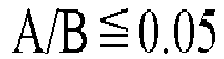 A is the maximum peak intensity between 10 degree to 20 degree in X-ray diffraction analysis, andB is the maximum peak intensity between 25 degree to 35 degree in X-ray diffraction analysis.
 - The negative electrode active material according to claim 1, wherein the transition metal carbide is selected from the group consisting of scandium carbide, yttrium carbide, dysprosium carbide, and titanium carbide.
- The negative electrode active material according to claim 1, wherein the transition metal carbide is represented by the following formula:


- A negative electrode active material layer for a fluoride ion battery, comprising the negative electrode active material according to any one of claims 1 to 4.
- The negative electrode active material layer according to claim 5, comprising the negative electrode active material, a solid electrolyte, and a conductive agent.
- A fluoride ion battery, comprising the negative electrode active material layer according to claim 5.
- The method for producing a negative electrode active material according to any one of claims 1 to 4, comprising applying a mechanical impact to a transition metal carbide having a layered structure to convert the transition metal carbide into a transition metal carbide having a non-layered structure.
- The method according to claim 8, wherein the transition metal carbide having the layered structure satisfies the following conditions:
 A is the maximum peak intensity between 10 degree to 20 degree in X-ray diffraction analysis, andB is the maximum peak intensity between 25 degree to 35 degree in X-ray diffraction analysis.
 - The method of claim 8, wherein the mechanical impact is applied by a ball mill.
Applications Claiming Priority (1)
| Application Number | Priority Date | Filing Date | Title |
|---|---|---|---|
| JP2023003252A JP7736725B2 (en) | 2023-01-12 | 2023-01-12 | Negative electrode active material for fluoride ion battery, negative electrode active material layer for fluoride ion battery, fluoride ion battery, and method for manufacturing negative electrode active material for fluoride ion battery |
Publications (1)
| Publication Number | Publication Date |
|---|---|
| EP4401171A1 true EP4401171A1 (en) | 2024-07-17 |
Family
ID=89536018
Family Applications (1)
| Application Number | Title | Priority Date | Filing Date |
|---|---|---|---|
| EP24150745.8A Pending EP4401171A1 (en) | 2023-01-12 | 2024-01-08 | Negative electrode active material for fluoride ion battery, negative electrode active material layer for fluoride ion battery, fluoride ion battery, and method for producing negative electrode active material for fluoride ion battery |
Country Status (5)
| Country | Link |
|---|---|
| US (1) | US20240243283A1 (en) |
| EP (1) | EP4401171A1 (en) |
| JP (1) | JP7736725B2 (en) |
| KR (1) | KR20240112747A (en) |
| CN (1) | CN118335974A (en) |
Citations (9)
| Publication number | Priority date | Publication date | Assignee | Title |
|---|---|---|---|---|
| WO2014207521A1 (en) * | 2013-06-27 | 2014-12-31 | Toyota Jidosha Kabushiki Kaisha | Electrode for non-aqueous secondary battery |
| JP2019204775A (en) | 2018-05-22 | 2019-11-28 | パナソニックIpマネジメント株式会社 | Active material for fluoride ion secondary battery, and fluoride ion secondary battery using the same |
| JP2020534652A (en) | 2017-10-04 | 2020-11-26 | 本田技研工業株式会社 | Anode for Fluoride Ion Battery |
| JP2020194668A (en) * | 2019-05-27 | 2020-12-03 | パナソニックIpマネジメント株式会社 | Fluoride ion active material for secondary batteries, and fluoride ion secondary battery using the same |
| JP2020194697A (en) | 2019-05-28 | 2020-12-03 | トヨタ自動車株式会社 | Fluoride ion battery |
| US20210151755A1 (en) * | 2019-11-18 | 2021-05-20 | The University Of North Carolina At Chapel Hill | Metal Carbides and Metal Nitrides for a Fluoride Ion Battery |
| US11038171B2 (en) * | 2018-05-22 | 2021-06-15 | Panasonic Intellectual Property Management Co., Ltd. | Active material including composite fluoride for fluoride ion secondary battery, and fluoride ion secondary battery using the same |
| CN113479855A (en) * | 2021-07-26 | 2021-10-08 | 武汉科技大学 | Method for preparing non-lamellar two-dimensional transition metal compound by using bulk phase lamellar transition metal sulfide |
| US11271204B2 (en) * | 2019-05-30 | 2022-03-08 | Panasonic Intellectual Property Management Co., Ltd. | Active material for fluoride-ion secondary battery and fluoride-ion secondary battery using same |
Family Cites Families (2)
| Publication number | Priority date | Publication date | Assignee | Title |
|---|---|---|---|---|
| JP7638592B2 (en) * | 2021-02-26 | 2025-03-04 | 本田技研工業株式会社 | Anode layer and fluoride ion secondary battery |
| JP7613422B2 (en) * | 2022-07-05 | 2025-01-15 | トヨタ自動車株式会社 | Fluoride ion battery and method for manufacturing the same |
-
2023
- 2023-01-12 JP JP2023003252A patent/JP7736725B2/en active Active
-
2024
- 2024-01-05 KR KR1020240002352A patent/KR20240112747A/en active Pending
- 2024-01-08 CN CN202410024889.0A patent/CN118335974A/en active Pending
- 2024-01-08 US US18/407,095 patent/US20240243283A1/en active Pending
- 2024-01-08 EP EP24150745.8A patent/EP4401171A1/en active Pending
Patent Citations (9)
| Publication number | Priority date | Publication date | Assignee | Title |
|---|---|---|---|---|
| WO2014207521A1 (en) * | 2013-06-27 | 2014-12-31 | Toyota Jidosha Kabushiki Kaisha | Electrode for non-aqueous secondary battery |
| JP2020534652A (en) | 2017-10-04 | 2020-11-26 | 本田技研工業株式会社 | Anode for Fluoride Ion Battery |
| JP2019204775A (en) | 2018-05-22 | 2019-11-28 | パナソニックIpマネジメント株式会社 | Active material for fluoride ion secondary battery, and fluoride ion secondary battery using the same |
| US11038171B2 (en) * | 2018-05-22 | 2021-06-15 | Panasonic Intellectual Property Management Co., Ltd. | Active material including composite fluoride for fluoride ion secondary battery, and fluoride ion secondary battery using the same |
| JP2020194668A (en) * | 2019-05-27 | 2020-12-03 | パナソニックIpマネジメント株式会社 | Fluoride ion active material for secondary batteries, and fluoride ion secondary battery using the same |
| JP2020194697A (en) | 2019-05-28 | 2020-12-03 | トヨタ自動車株式会社 | Fluoride ion battery |
| US11271204B2 (en) * | 2019-05-30 | 2022-03-08 | Panasonic Intellectual Property Management Co., Ltd. | Active material for fluoride-ion secondary battery and fluoride-ion secondary battery using same |
| US20210151755A1 (en) * | 2019-11-18 | 2021-05-20 | The University Of North Carolina At Chapel Hill | Metal Carbides and Metal Nitrides for a Fluoride Ion Battery |
| CN113479855A (en) * | 2021-07-26 | 2021-10-08 | 武汉科技大学 | Method for preparing non-lamellar two-dimensional transition metal compound by using bulk phase lamellar transition metal sulfide |
Non-Patent Citations (3)
| Title |
|---|
| DATABASE WPI Week 2020099, Derwent World Patents Index; AN 2020-C0344U, XP002811627 * |
| DATABASE WPI Week 2022007, Derwent World Patents Index; AN 2021-B89325, XP002811626 * |
| GAO YIN-HONG ET AL: "Non-layer transition metal carbides for energy conversion and storage", CARBON, ELSEVIER OXFORD, GB, vol. 183, 9 September 2021 (2021-09-09), pages 1013, XP086770749, ISSN: 0008-6223, DOI: 10.1016/J.CARBON.2021.07.089 * |
Also Published As
| Publication number | Publication date |
|---|---|
| JP7736725B2 (en) | 2025-09-09 |
| JP2024099360A (en) | 2024-07-25 |
| US20240243283A1 (en) | 2024-07-18 |
| CN118335974A (en) | 2024-07-12 |
| KR20240112747A (en) | 2024-07-19 |
Similar Documents
| Publication | Publication Date | Title |
|---|---|---|
| CN115020799B (en) | Solid electrolyte materials and batteries | |
| EP3996179A1 (en) | Battery | |
| WO2019135344A1 (en) | Solid electrolyte material, and battery | |
| CN116885271A (en) | Solid electrolyte materials and batteries | |
| CN110518191B (en) | Active material for fluoride ion secondary battery and fluoride ion secondary battery using the same | |
| JPWO2018092359A1 (en) | Positive electrode active material for battery and battery | |
| EP4047694A1 (en) | Battery | |
| JP2018085324A (en) | Battery positive electrode active material and battery using battery positive electrode active material | |
| EP4106044A1 (en) | Solid electrolyte material and battery using same | |
| EP4007013B1 (en) | Negative electrode material for nonaqueous electrolyte secondary batteries, and nonaqueous electrolyte secondary battery | |
| US20240178383A1 (en) | Electrode and battery | |
| US20230335724A1 (en) | Doped sodium anode, battery having a doped sodium anode, and methods of use thereof | |
| KR20220015410A (en) | Electrode Materials Comprising Layered Potassium Metal Oxide, Electrodes Comprising Electrode Materials and Use of Electrode Materials in Electrochemistry | |
| WO2020240890A1 (en) | Active material for fluoride ion secondary batteries, and fluoride ion secondary battery using same | |
| KR102824803B1 (en) | Fluoride ion battery and method for producing fluoride ion battery | |
| CN115968505B (en) | Positive electrode active material for secondary batteries and secondary batteries | |
| US20250015286A1 (en) | Oxyhalide material, battery, and battery system | |
| JP7147726B2 (en) | Active materials and fluoride ion batteries | |
| EP4401171A1 (en) | Negative electrode active material for fluoride ion battery, negative electrode active material layer for fluoride ion battery, fluoride ion battery, and method for producing negative electrode active material for fluoride ion battery | |
| CN113363451B (en) | Cathode active material and fluoride ion battery | |
| CN117882214A (en) | Positive electrode active material for secondary battery and secondary battery | |
| KR102928523B1 (en) | Fluoride-ion battery, negative electrode active material for fluoride-ion battery, and method for manufacturing negative electrode active material for fluoride-ion battery | |
| CN115084496B (en) | Active materials and fluoride ion batteries | |
| US12027701B2 (en) | Active material and fluoride ion battery | |
| US20230395799A1 (en) | Positive electrode active material for fluoride ion battery and fluoride ion battery |
Legal Events
| Date | Code | Title | Description |
|---|---|---|---|
| PUAI | Public reference made under article 153(3) epc to a published international application that has entered the european phase |
Free format text: ORIGINAL CODE: 0009012 |
|
| STAA | Information on the status of an ep patent application or granted ep patent |
Free format text: STATUS: REQUEST FOR EXAMINATION WAS MADE |
|
| 17P | Request for examination filed |
Effective date: 20240125 |
|
| AK | Designated contracting states |
Kind code of ref document: A1 Designated state(s): AL AT BE BG CH CY CZ DE DK EE ES FI FR GB GR HR HU IE IS IT LI LT LU LV MC ME MK MT NL NO PL PT RO RS SE SI SK SM TR |