EP4401108B1 - Spare fuse clip - Google Patents
Spare fuse clip Download PDFInfo
- Publication number
- EP4401108B1 EP4401108B1 EP23220805.8A EP23220805A EP4401108B1 EP 4401108 B1 EP4401108 B1 EP 4401108B1 EP 23220805 A EP23220805 A EP 23220805A EP 4401108 B1 EP4401108 B1 EP 4401108B1
- Authority
- EP
- European Patent Office
- Prior art keywords
- fuse
- clip
- track
- underhang
- spare
- Prior art date
- Legal status (The legal status is an assumption and is not a legal conclusion. Google has not performed a legal analysis and makes no representation as to the accuracy of the status listed.)
- Active
Links
Images





Classifications
-
- H—ELECTRICITY
- H01—ELECTRIC ELEMENTS
- H01H—ELECTRIC SWITCHES; RELAYS; SELECTORS; EMERGENCY PROTECTIVE DEVICES
- H01H85/00—Protective devices in which the current flows through a part of fusible material and this current is interrupted by displacement of the fusible material when this current becomes excessive
- H01H85/02—Details
- H01H85/20—Bases for supporting the fuse; Separate parts thereof
-
- H—ELECTRICITY
- H01—ELECTRIC ELEMENTS
- H01H—ELECTRIC SWITCHES; RELAYS; SELECTORS; EMERGENCY PROTECTIVE DEVICES
- H01H85/00—Protective devices in which the current flows through a part of fusible material and this current is interrupted by displacement of the fusible material when this current becomes excessive
- H01H85/02—Details
- H01H85/20—Bases for supporting the fuse; Separate parts thereof
- H01H85/2045—Mounting means or insulating parts of the base, e.g. covers, casings
-
- H—ELECTRICITY
- H01—ELECTRIC ELEMENTS
- H01H—ELECTRIC SWITCHES; RELAYS; SELECTORS; EMERGENCY PROTECTIVE DEVICES
- H01H85/00—Protective devices in which the current flows through a part of fusible material and this current is interrupted by displacement of the fusible material when this current becomes excessive
- H01H85/02—Details
- H01H85/22—Intermediate or auxiliary parts for carrying, holding, or retaining fuse, co-operating with base or fixed holder, and removable therefrom for renewing the fuse
-
- H—ELECTRICITY
- H01—ELECTRIC ELEMENTS
- H01H—ELECTRIC SWITCHES; RELAYS; SELECTORS; EMERGENCY PROTECTIVE DEVICES
- H01H85/00—Protective devices in which the current flows through a part of fusible material and this current is interrupted by displacement of the fusible material when this current becomes excessive
- H01H85/02—Details
- H01H85/26—Magazine arrangements
- H01H85/263—Magazine arrangements with spare printed circuit fuse
-
- H—ELECTRICITY
- H01—ELECTRIC ELEMENTS
- H01H—ELECTRIC SWITCHES; RELAYS; SELECTORS; EMERGENCY PROTECTIVE DEVICES
- H01H85/00—Protective devices in which the current flows through a part of fusible material and this current is interrupted by displacement of the fusible material when this current becomes excessive
- H01H85/02—Details
- H01H85/20—Bases for supporting the fuse; Separate parts thereof
- H01H2085/2065—Bases for supporting the fuse; Separate parts thereof with base contacts adapted or adaptable to fuses of different lenghts; bases with self-aligning contacts; intermediate adaptation pieces
-
- H—ELECTRICITY
- H01—ELECTRIC ELEMENTS
- H01H—ELECTRIC SWITCHES; RELAYS; SELECTORS; EMERGENCY PROTECTIVE DEVICES
- H01H85/00—Protective devices in which the current flows through a part of fusible material and this current is interrupted by displacement of the fusible material when this current becomes excessive
- H01H85/02—Details
- H01H85/0208—Tools for inserting and removing fuses
-
- H—ELECTRICITY
- H01—ELECTRIC ELEMENTS
- H01H—ELECTRIC SWITCHES; RELAYS; SELECTORS; EMERGENCY PROTECTIVE DEVICES
- H01H85/00—Protective devices in which the current flows through a part of fusible material and this current is interrupted by displacement of the fusible material when this current becomes excessive
- H01H85/02—Details
- H01H85/20—Bases for supporting the fuse; Separate parts thereof
- H01H85/203—Bases for supporting the fuse; Separate parts thereof for fuses with blade type terminals
-
- H—ELECTRICITY
- H01—ELECTRIC ELEMENTS
- H01H—ELECTRIC SWITCHES; RELAYS; SELECTORS; EMERGENCY PROTECTIVE DEVICES
- H01H85/00—Protective devices in which the current flows through a part of fusible material and this current is interrupted by displacement of the fusible material when this current becomes excessive
- H01H85/02—Details
- H01H85/26—Magazine arrangements
Definitions
- Embodiments of the present disclosure relate to fuse holders and, more particularly, for fuse holders that accommodate spare fuses.
- Fuses are current-sensitive devices designed to be the intentional weak link in an electrical circuit. Fuses come in a variety of form factors, including bolt-down fuses.
- Bolt-down fuses feature a fuse body with two terminals extending therefrom, where one or more of the terminals is bolted down to a surface, such as a busbar or printed circuit board (PCB).
- PCB printed circuit board
- fuse holders which are a generally airtight housing for the fuse.
- the fuse holder may have busbars or PCBs therein, with cables extending from the fuse to the circuit(s) to be protected.
- More extensive fuse holders may include low-voltage power distribution modules and high-voltage power distribution units, which house relays in addition to fuses.
- the housing of the fuse holder may be a clam-shell type, with a cover portion already connected to the housing, or the fuse holder may have a separate cover, due to the fact that the fuse holder needs to be accessed when changing the fuse.
- the fuse holder will also house one or more spare fuses.
- the typical arrangement is to have the spare fuses bolted down to the housing, which necessitates that the housing be sized to accommodate the particular fuse size. There is also the possibility that the bolts will get lost during the fuse change operation.
- the fuse housing may also have a plug-in arrangement for holding spare fuses, which does not successfully accommodate fuses of different sizes.
- An exemplary embodiment of a fuse holder in accordance with the present disclosure may include a housing, a clip, and a cover.
- the housing is for a fuse, and the fuse is to be connected to and protecting a circuit.
- the clip includes a base, a pair of shafts, an overhead, and an underhang.
- the base is for seating a spare fuse.
- the pair of shafts are on and perpendicular to the base.
- the overhead is located on and supported by the pair of shafts.
- the underhang is beneath the overhang and deforms in response to the movement of the spare fuse along the base toward the shaft.
- the cover is placed over the housing to form an enclosed space around the fuse and the clip.
- An exemplary embodiment of a clip in accordance with the present disclosure may include a shaft, an overhead, and an underhang.
- the shaft is located on and perpendicular to a base.
- the overhead is on and supported by the shaft and is triangular prism-shaped.
- the underhang is attached to the overhead. The underhang and the base secure a spare fuse.
- a fuse holder for holding working fuses features a spare fuse holder inside the housing of the fuse holder.
- the spare fuse holder includes a clip that has an elastic underhang for exerting pressure on the fuse as it is slid into place in the clip.
- the clip also has a base with some angled surfaces, two shafts orthogonal to the base for providing structural support, and, between the shafts, a fuse release for enabling ease of removal of the spare fuse.
- the spare fuse holder is suitable for bolt-down fuses with various current ratings. Unlike the bolt-down type, the spare fuse holder does not use bolts for holding the spare fuse. Unlike the plug-in type, the spare fuse holder successfully holds fuses of different fuse body sizes, terminal sizes, and current ratings.
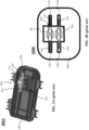
- FIG. 1 is a representative drawing of a fuse holder 100 (perspective view) for holding fuses and spare fuses, according to exemplary embodiments.
- the fuse holder 100 includes a housing 108 to hold two fuses 102a and 102b (collectively, "fuses 102").
- the fuses 102 are bolt-down fuses.
- the fuse holder 100 also features a busbar 104 which is distributed in several locations in the fuse holder 100.
- the fuses 102 are each connected at one end to the busbar 104.
- Bolts 106a-c (collectively, “bolts 106") enable connections to be made between the fuse holder 100 and one or more cables or other busbars (not shown).
- Clamps 112a-d (collectively, “clamps 112") enable a cover to be attached to the housing 108, thus ensuring that there is a somewhat air-tight seal for the contents inside the fuse holder 100.
- Mounting brackets 114a-b (collectively, “mounting brackets 114") include apertures for bolting the fuse holder 100 to a surface, although the mounting brackets may be attached to the surface in another way, as this is a non-limiting example.
- the fuse holder 100 features a spare fuse holder 110, shown in the dashed circle.
- the spare fuse holder 110 overcomes the deficiencies of the prior art by accommodating fuses of different sizes.
- the spare fuse holder 110 holds bolt-down fuses, although the design is not limited in this respect.
- the spare fuse holder 110 is flexible enough to accommodate a variety of different fuse types and shapes.
- FIGs. 2A-2E are representative drawings of fuse holders and bolt-down fuses, according to the prior art.
- FIG. 2A is a perspective view of a first fuse holder 200A
- FIG. 2B is an overhead view of a second fuse holder 200B
- FIGs. 2C-2E are perspective views of bolt-down fuses 20a-c (collectively, "spare fuse holders 200" and "bolt-down fuses 202").
- the fuse holders 200 do not include the fuses, busbars, bolts, and clamps that characterize typical fuse holders, as these drawings are intended to show and describe the spare fuse holder portion of these devices.
- a fuse 202a is disposed in the fuse holder 200A ( FIG. 2A ), fuses 202b and 202c are disposed in the fuse holder 200B ( FIG. 2B ), and fuses 202d ( FIG. 2C ), 202e ( FIG. 2D ), and 202f ( FIG. 2E ) are shown (collectively, "fuses 202").
- Each fuse 202 includes a fuse body and two terminals, with fuse 202a having terminal 210a, fuse body 212a and terminal 210b ( FIG. 2A ), fuse 202b having terminal 210c, fuse body 212b, and terminal 210d, fuse 202c having terminal 210e, fuse body 212c, and terminal 210f ( FIG.
- terminal 210 having terminal 210g, fuse body 212d, and terminal 210h ( FIG. 2C ), fuse 202e having terminal 210i, fuse body 212e, and terminal 210j ( FIG. 2D ), and fuse 202f having terminal 210k, fuse body 212f, and terminal 2101 ( FIG. 2E ) (collectively, “terminals 210" and "fuse bodies 212").
- the fuse holder 200A features a housing 208a with a location for placing the spare fuse 202a.
- the fuse holder 200 holds the spare fuse 202a using bolts 204a and 204b (collectively, "bolts 204").
- the fuse holder 200A is thus a "screwing design" of fuse holder since the bolts 204 are screwed into the housing 208a to secure the spare fuse 202a.
- the housing 208a would be assembled with the specific dimensions of the fuse 202a in mind.
- a screwdriver would be needed to remove the bolts 204 and there is some risk that the bolts would be lost during this process. Further, having the bolts will result in additional assembly time including the process of securing the spare fuse.
- the fuse holder 200B features a housing 208b with a fuse receptacle 206 suitable for holding the two fuses 202b and 202c.
- the fuse holder 200B is thus a "plug-in design" of fuse holder, since the fuses 202b and 202c are simply plugged into the fuse receptacle 206 (no bolts are needed).
- the fuse receptacle 206 includes four terminal holders 216a-d (collectively, "terminal receptacles 216”), one for each terminal 210 of the two fuses.
- the terminal holders 216 are designed to clamp the terminals 210 so that the fuses 202 stay in place in the fuse receptacle 206.
- the fuse 202b is larger than the fuse 202c and, due to a difference in current rating between the two fuses, the terminals 210c and 210d are longer and thicker than the terminals 210e and 210f. Although able to hold both fuses 202b and 202c, the terminals holders 216 of the fuse receptacle 206 are all the same size. Thus, the fuse receptacle is sized for the larger fuse 202b and the terminal holder 216a successfully clamps the terminal 210c of the fuse 202b while the terminal holder 216c successfully clamps the terminal 210d of the fuse 202b.
- the fuse 202c may not be fully clamped by respective terminal holders 216b and 216d of the fuse receptacle 206.
- the smaller fuse 202c may fall out of the fuse receptacle 206, such as when a cover (not shown) is removed from the housing 208b of the fuse holder 200B, which is not a desired outcome.
- the fuse receptacle 206 of the fuse holder 200B could be designed differently. That is, the terminal holders 216b and 216d could be made smaller, for fuses of lower current rating. This, however, limits the fuses that can be accepted by the fuse receptacle 206, which is also not a desired outcome.
- the three bolt-down fuses 202d, 202e, and 202f of FIGs. 2C-2E may be suitable for either the screwing design fuse holder 200A or the plug-in design fuse holder 200B. Although similar in shape, there are some differences between the bolt-down fuses 202d, 202e, and 202f.
- the terminals 210i and 210j (of bolt-down fuse 202e) and the terminals 210k and 2101 (of bolt-down fuse 202f) each have apertures, with terminal 210i having aperture 214b, terminal 210j having aperture 214c, terminal 210k having aperture 214d, and terminal 2101 having aperture 214e.
- terminal 210g has an aperture 214a (collectively, "apertures 214"), but terminal 210h has no aperture.
- the bolt-down fuse 202d would not be suitable for the fuse holder 200A, as the spare fuse is affixed to the housing 208a using two bolts 204.
- the bolt-down fuses 202d, 202e, and 202f are different sizes and have different current ratings.
- the bolt-down fuses 202d-f may not be suitable for the fuse holder 200B.
- FIGs. 3A-3B are representative drawings of the fuse holder 100 of FIG. 1 , according to exemplary embodiments.
- FIG. 3A is a perspective view and FIG. 3B is a close-up cross-sectional perspective view of the fuse holder 100.
- the fuse holder 100 is an improvement over the prior art fuse holders 200 in several respects.
- the fuse holder 100 features a special clip design to hold spare fuses. Compared with the legacy bolt-down and plug-in fuse holders, the fuse holder 100 is more versatile, as the special clip design can support a variety of types of bolt-down fuses.
- the fuse holder 100 can support bolt-down fuses having different sizes and current ratings, as well as supporting bolt-down fuses having single-aperture terminals such as the bolt-down fuse 202d ( FIG. 2C ). Further, in some embodiments, the fuse holder 100 can support fuses other than bolt-down fuses.
- the spare fuse holder 110 introduced in FIG. 1 is shown in FIGs. 3A and 3B .
- the fuse 102 which is not a replacement fuse, but is a fuse being used to protect a circuit connected to the fuse holder 100, is also shown in FIG. 3A .
- the position of the spare fuse holder 110 may differ from what is shown in FIGs. 1 , 3A, and 3B , in a non-limiting embodiment.
- a cover 302 is placed over the housing 108 to form an enclosed spaced which encapsulates both the fuse 102 and the spare fuse holder 110.
- the housing 108 and cover 302 are plastic.
- the fuse holder 100 includes a seal 304 which surrounds the perimeter of a top portion of the housing 108.
- the seal 304 may surround the perimeter of a top portion of the cover 302.
- the seal 304 is elastomeric and provides an airtight enclosed space for the fuse 102 and the spare fuse holder 110.
- the spare fuse holder 110 includes a clip 308 and a fuse 306.
- the fuse 306 is shown as a rectangular cube to represent a generalized shape of the body of a fuse, such as one of the fuse bodies 212 shown in FIGs. 2C-2E .
- the clip 308 is capable of holding any thickness of fuses tightly.
- the fuses are easy to load and unload and are particularly more convenient than the bolt-down spare fuse holders.
- the spare fuse holder 110 is capable of holding a fuse having a fuse body of up to 12mm with stability. Further, the design of the spare fuse holder 110 can be scaled for larger fuses, including high-voltage fuses, in some embodiments.
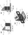
- FIG. 4A-4F are representative drawings of the spare fuse holder 110 that is part of the fuse holder 100 of FIG. 1 , according to exemplary embodiments.
- FIG. 4A is a side cross-sectional view of the spare fuse holder 110 before the fuse is installed (clip is in a resting state)
- FIG. 4B is a side view of the spare fuse holder after the fuse is installed (clip is in holding state)
- FIG. 4C is a perspective view of the spare fuse holder with the fuse installed
- FIG. 4D is a perspective view of the clip without the fuse
- FIG. 4E is a cross-sectional perspective view of the clip
- FIG. 4F is a side view of the spare fuse holder with the fuse installed (clip is in holding state).
- the clip 308 features a base 402, a pair of shafts 406a-b (collectively, "shafts 406"), and an overhead 404, with both shafts being visible in FIG. 4D .
- the base 402 is for seating the spare fuse 306 and the shafts are orthogonal (perpendicular) to the base and support the overhead.
- the overhead 404 has three sides 432, 434, and 436 which form a triangular prism. From the side, such as in the views of FIGs.
- the overhead 404 resembles a right triangle, with a first side 432 (bottom, horizontal side) being an extension of the shaft 406, a second side 434 (vertical side) being perpendicular to the first side, and the third side 436 (right-angled side) being angled.
- the third side 436 is at a 45° angle relative to the first side 432 and the second side 434.
- the overhead 404 further has an opening 416 that cuts away the central part of the first side 432 and the third side 436, exposing an inner portion of the second side 434.
- the overhead 404 is a hollowed out triangular prism.
- An underhang 412 is disposed beneath and attached to the overhead 404. As shown particularly in the cross-sectional view of FIG. 4E , the underhang 412 extends downward from the side 432 of the overhead 404, and is curved so that, except for the end connection to the overhead, is substantially parallel to the side 432 in its resting state.
- the underhang 412 is an elastomeric material having the ability to deform its shape in reaction to pressure, e.g., the pressure coming from the top of the spare fuse 306, which causes the underhang 412 to compress toward the overhang 404, e.g., in an upward direction.
- both the underhang 412 and the overhead 404 are elastomeric.
- a fuse release 414 Beneath the third side 434 of the overhang 404 and disposed between the shafts 406 is a fuse release 414.
- the fuse release 414 is most visible in FIG. 4A , as only the shaft 406b is visible.
- the fuse release 414 extends downward from the side 434 of the overhead 404.
- the fuse release 414 has an angular side that juts out from the back of the clip 308, making it easy to push the fuse release, and a second curved side opposite the angular side that pushes against the fuse body 422 when the fuse release 414 is pushed (depressed) toward the region in between the two shafts 406.
- the fuse release 414 pushes the spare fuse 306 away from the pair of shafts 406, causing the spare fuse to be released from the clip 308.
- the fuse release 414 is an elastomeric material having the ability to deform its shape in reaction to pressure. By being pressed, the fuse release 414 moves toward the installed spare fuse 306, which causes the spare fuse 306 to move out from under the clip 308.
- the base 402 consists of three surfaces, a surface 420a, a surface 420b, and a surface 420c (collectively, “surfaces 420"). Although substantially planar to one another, the surfaces 420a and 420b are angled slightly, to facilitate leading the spare fuse 306 to the clip 308. Extending across the surfaces, 420 are two tracks 408a and 408b (collectively, “tracks 408"). The tracks 408 are rectangular cutouts which are perpendicular to the surfaces 420, are disposed adjacent two opposing sides ends of the base 402, and have a depth that is slightly less than the height, h, of the base 402.
- Each track 408 has a fuse clip, with track 408a having fuse clip 418a and track 408b having fuse clip 418b (collectively, "fuse clips 418").
- the fuse clips 418 are close to the side of the tracks 408 that are adjacent the shafts 406.
- the fuse clips 418 have an angled tip portion 426 ( FIG. 4E ) that, when pressed, will cause each fuse clip to move into the cavity (channel) of its respective track 408. In the illustrated embodiments, the movement of each fuse clip 418 would be downward into the respective tracks 408.
- a close-up view of the angled tip portion 426 is shown in FIG. 5D , below.
- the depths of the tracks 408 are slightly greater than a height, h 2 , of the angled tip portion 426 of the fuse clips 418 (see FIG. 5D ).
- the fuse clips 418 are elastomeric, in exemplary embodiments.
- the base 402, the shaft 406, the overhead 404, the underhang 412, the fuse release 414, and the fuse clips 418 are made of a thermoplastic material using injection molding operations.
- the overhead 404, underhang 412, the fuse release 414, and the fuse clips 418 are impregnated with an elastomeric material, thus allowing the clip 308 to be both flexible in the impregnated regions and rigid in the other, non-impregnated regions.
- the base 402, shafts 406, and overhead 404 are a support structure for the spare fuse 306.
- the spare fuse 306 is a bolt-down fuse, which has a fuse body 422 and terminals 410a-b (collectively, “terminals 410"), with the fuse body having three portions 424a-c (collectively, "portions 424").
- the track 408a is a distance, d, from the track 408b, where the distance, d, is larger than the width, w, of portions 424a and 424c of the fuse body 422, as the width of portion 424a is substantially similar to the width of portion 424c (see FIG. 4C ).
- the portion 424b is wider than the portions 414a and 424c (see FIG.
- the portion 424b slides over the tracks 408 but the portions 424a and 424c do not slide over the tracks.
- the portion 424b pushes against the angled tip portion 426 of respective fuse clips 418, causing the fuse clips to move downward into respective tracks 408.
- the portion 424a does not contact the fuse clips 418.
- the portion 424b does contact the fuse clips 418 and pushes them down into the tracks 408.
- the portion 424b of the fuse body 422 moves past the fuse clips 418 and the fuse clips move again upward from the tracks 408.
- the angled tip portion 426 of the fuse clips 418 act as a stop to the spare fuse 306.
- the fuse clips 418 may remain in the down position within the tracks 408, in some embodiments. Because the underhang 412 is exerting downward pressure thereon, the spare fuse will nevertheless remain in place within the clip 308.
- the length of the fuse clips 418 or the size and shape of the angled tip portion 426 may be adjusted to support a spare fuse having a different fuse body than the fuse body 422 of the spare fuse 306.
- FIGs. 5A-5D are representative drawings of the spare fuse holder 110 of the fuse holder 100 of FIG. 1 , according to exemplary embodiments.
- FIGs. 5A-5C are side views of the spare fuse holder 110, with FIG. 5A showing a first fuse insertion point (clip is in resting state), FIG. 5B showing a second fuse insertion point (clip is in activated state), and FIG. 5C showing a third fuse insertion point (clip is in holding state), and FIG. 5D is a detailed perspective view of the fuse clip position at the third fuse insertion point.
- FIGs. 5A-5C are side views of the spare fuse holder 110, with FIG. 5A showing a first fuse insertion point (clip is in resting state), FIG. 5B showing a second fuse insertion point (clip is in activated state), and FIG. 5C showing a third fuse insertion point (clip is in holding state), and FIG. 5D is a detailed perspective view of the fuse clip position at the third fuse insertion point.
- the overhead 404 and underhang 412 include cross-hatching to indicate a flexion or pressure-based deformation due to the sliding of the spare fuse 306 toward the shaft 406 of the clip 308.
- the clip 308 is in a resting state when the underhang has not been deformed; the clip is in an activated state when the underhang is deformed and the fuse clips have been pushed into the respective tracks 408; and the clip is in a holding state when the underhang is deformed and the fuse clips are no longer pushed into the respective tracks but have returned to an original position.
- the spare fuse 306 is adjacent, but not yet under the overhead 404 and underhang 412 of the clip 308.
- the portion 424a does not touch the angled tip portions 426 of the fuse clips 418, so the fuse clips remain undisturbed as well.
- the slanted surfaces 420a and 420b of the base 402 are slightly angled, allowing the spare fuse 306 to readily move toward the shafts 406 of the clip 308.
- the spare fuse 306 is moved toward the shaft 406 of the clip 308, and the underhang 412 deforms upward, as the spare fuse is compressing the underhang 412 toward the overhead 404.
- the portion 424a of the fuse body 422 is fully under the underhang 412 and the portion 424b is partially under the underhang. Further, the portion 424b is pushing against the angled tip portion 426 of the fuse clips 418, causing the fuse clips to move downward into their respective tracks 408.
- Both the underhang 412 and the overhead 404 are cross-hatched, indicating some flexion in response to the movement of the spare fuse 306 along the base 402 toward the shaft 406. Although the overhead 404 flexes a little, the shaft 406 of the clip 308 remains rigid, in some embodiments.
- the spare fuse 306 is fully engaged with the clip 308, with portion 424a being flush against the shafts 406.
- portion 424b moves past the angled tip portion 426 of the fuse clips 418, the fuse clips move from a downward position inside the tracks 408 back to the original position.
- the backside of the angled tip portion 426 is flush against the portion 424b of the fuse body 422.
Landscapes
- Fuses (AREA)
Description
- Embodiments of the present disclosure relate to fuse holders and, more particularly, for fuse holders that accommodate spare fuses.
- Fuses are current-sensitive devices designed to be the intentional weak link in an electrical circuit. Fuses come in a variety of form factors, including bolt-down fuses. Bolt-down fuses feature a fuse body with two terminals extending therefrom, where one or more of the terminals is bolted down to a surface, such as a busbar or printed circuit board (PCB).
- Some fuses are contained in a fuse holder, which is a generally airtight housing for the fuse. The fuse holder may have busbars or PCBs therein, with cables extending from the fuse to the circuit(s) to be protected. More extensive fuse holders may include low-voltage power distribution modules and high-voltage power distribution units, which house relays in addition to fuses.
- The housing of the fuse holder may be a clam-shell type, with a cover portion already connected to the housing, or the fuse holder may have a separate cover, due to the fact that the fuse holder needs to be accessed when changing the fuse. Occasionally, the fuse holder will also house one or more spare fuses. The typical arrangement is to have the spare fuses bolted down to the housing, which necessitates that the housing be sized to accommodate the particular fuse size. There is also the possibility that the bolts will get lost during the fuse change operation. The fuse housing may also have a plug-in arrangement for holding spare fuses, which does not successfully accommodate fuses of different sizes.
- It is with respect to these and other considerations that the present improvements may be useful.
- The document
WO 2014/181655 A1 discloses a fuse holder according to the preamble of claim 1. - This Summary is provided to introduce a selection of concepts in a simplified form that are further described below in the Detailed Description. This Summary is not intended to identify key or essential features of the claimed subject matter, nor is it intended as an aid in determining the scope of the claimed subject matter.
- An exemplary embodiment of a fuse holder in accordance with the present disclosure may include a housing, a clip, and a cover. The housing is for a fuse, and the fuse is to be connected to and protecting a circuit. The clip includes a base, a pair of shafts, an overhead, and an underhang. The base is for seating a spare fuse. The pair of shafts are on and perpendicular to the base. The overhead is located on and supported by the pair of shafts. The underhang is beneath the overhang and deforms in response to the movement of the spare fuse along the base toward the shaft. The cover is placed over the housing to form an enclosed space around the fuse and the clip.
- An exemplary embodiment of a clip in accordance with the present disclosure, not part of the invention, may include a shaft, an overhead, and an underhang. The shaft is located on and perpendicular to a base. The overhead is on and supported by the shaft and is triangular prism-shaped. The underhang is attached to the overhead. The underhang and the base secure a spare fuse.
-
-
FIG. 1 is a diagram illustrating a fuse holder for holding a spare fuse, in accordance with exemplary embodiments; -
FIGs. 2A-2E are diagrams illustrating fuse holders and bolt-down fuses, in accordance with the prior art; -
FIGs. 3A-3B are diagrams illustrating the fuse holder ofFIG. 1 , in accordance with exemplary embodiments; -
FIGs. 4A-4F are diagrams illustrating a special clip used by the fuse holder ofFIG. 1 , in accordance with exemplary embodiments; and -
FIGs. 5A-5D are diagrams illustrating a special clip used by the fuse holder ofFIG. 1 , in accordance with exemplary embodiments. - A fuse holder for holding working fuses features a spare fuse holder inside the housing of the fuse holder. The spare fuse holder includes a clip that has an elastic underhang for exerting pressure on the fuse as it is slid into place in the clip. The clip also has a base with some angled surfaces, two shafts orthogonal to the base for providing structural support, and, between the shafts, a fuse release for enabling ease of removal of the spare fuse. The spare fuse holder is suitable for bolt-down fuses with various current ratings. Unlike the bolt-down type, the spare fuse holder does not use bolts for holding the spare fuse. Unlike the plug-in type, the spare fuse holder successfully holds fuses of different fuse body sizes, terminal sizes, and current ratings.
- For the sake of convenience and clarity, terms such as "top", "bottom", "upper", "lower", "vertical", "horizontal", "lateral", "transverse", "radial", "inner", "outer", "left", and "right" may be used herein to describe the relative placement and orientation of the features and components, each with respect to the geometry and orientation of other features and components appearing in the perspective, exploded perspective, and cross-sectional views provided herein. Said terminology is not intended to be limiting and includes the words specifically mentioned, derivatives therein, and words of similar import.
-
FIG. 1 is a representative drawing of a fuse holder 100 (perspective view) for holding fuses and spare fuses, according to exemplary embodiments. Thefuse holder 100 includes ahousing 108 to hold twofuses fuses 102 are bolt-down fuses. Thefuse holder 100 also features abusbar 104 which is distributed in several locations in thefuse holder 100. Thefuses 102 are each connected at one end to thebusbar 104.Bolts 106a-c (collectively, "bolts 106") enable connections to be made between thefuse holder 100 and one or more cables or other busbars (not shown).Clamps 112a-d (collectively, "clamps 112") enable a cover to be attached to thehousing 108, thus ensuring that there is a somewhat air-tight seal for the contents inside thefuse holder 100.Mounting brackets 114a-b (collectively, "mounting brackets 114") include apertures for bolting thefuse holder 100 to a surface, although the mounting brackets may be attached to the surface in another way, as this is a non-limiting example. - In exemplary embodiments, the
fuse holder 100 features aspare fuse holder 110, shown in the dashed circle. As will be shown, thespare fuse holder 110 overcomes the deficiencies of the prior art by accommodating fuses of different sizes. In exemplary embodiments, thespare fuse holder 110 holds bolt-down fuses, although the design is not limited in this respect. As will be shown, thespare fuse holder 110 is flexible enough to accommodate a variety of different fuse types and shapes. -
FIGs. 2A-2E are representative drawings of fuse holders and bolt-down fuses, according to the prior art.FIG. 2A is a perspective view of afirst fuse holder 200A,FIG. 2B is an overhead view of asecond fuse holder 200B, andFIGs. 2C-2E are perspective views of bolt-down fuses 20a-c (collectively, "spare fuse holders 200" and "bolt-down fuses 202"). For simplicity, the fuse holders 200 do not include the fuses, busbars, bolts, and clamps that characterize typical fuse holders, as these drawings are intended to show and describe the spare fuse holder portion of these devices. - A
fuse 202a is disposed in thefuse holder 200A (FIG. 2A ), fuses 202b and 202c are disposed in thefuse holder 200B (FIG. 2B ), and fuses 202d (FIG. 2C ), 202e (FIG. 2D ), and 202f (FIG. 2E ) are shown (collectively, "fuses 202"). Each fuse 202 includes a fuse body and two terminals, withfuse 202a having terminal 210a, fusebody 212a and terminal 210b (FIG. 2A ),fuse 202b having terminal 210c,fuse body 212b, and terminal 210d,fuse 202c having terminal 210e, fusebody 212c, and terminal 210f (FIG. 2B ),fuse 202d havingterminal 210g,fuse body 212d, and terminal 210h (FIG. 2C ),fuse 202e havingterminal 210i,fuse body 212e, and terminal 210j (FIG. 2D ), and fuse202f having terminal 210k,fuse body 212f, and terminal 2101 (FIG. 2E ) (collectively, "terminals 210" and "fuse bodies 212"). - The
fuse holder 200A features ahousing 208a with a location for placing thespare fuse 202a. The fuse holder 200 holds thespare fuse 202a usingbolts fuse holder 200A is thus a "screwing design" of fuse holder since the bolts 204 are screwed into thehousing 208a to secure thespare fuse 202a. With such a design, thehousing 208a would be assembled with the specific dimensions of thefuse 202a in mind. Further, to access thefuse 202a (to replace a blow fuse), a screwdriver would be needed to remove the bolts 204 and there is some risk that the bolts would be lost during this process. Further, having the bolts will result in additional assembly time including the process of securing the spare fuse. - The
fuse holder 200B features ahousing 208b with afuse receptacle 206 suitable for holding the twofuses fuse holder 200B is thus a "plug-in design" of fuse holder, since thefuses fuse receptacle 206 includes fourterminal holders 216a-d (collectively, "terminal receptacles 216"), one for each terminal 210 of the two fuses. The terminal holders 216 are designed to clamp the terminals 210 so that the fuses 202 stay in place in thefuse receptacle 206. - The
fuse 202b is larger than thefuse 202c and, due to a difference in current rating between the two fuses, theterminals terminals fuses fuse receptacle 206 are all the same size. Thus, the fuse receptacle is sized for thelarger fuse 202b and theterminal holder 216a successfully clamps the terminal 210c of thefuse 202b while theterminal holder 216c successfully clamps the terminal 210d of thefuse 202b. The same is not true for thefuse 202c, as theterminals terminal holders fuse receptacle 206. Thesmaller fuse 202c may fall out of thefuse receptacle 206, such as when a cover (not shown) is removed from thehousing 208b of thefuse holder 200B, which is not a desired outcome. - The
fuse receptacle 206 of thefuse holder 200B could be designed differently. That is, theterminal holders fuse receptacle 206, which is also not a desired outcome. - The three bolt-down
fuses FIGs. 2C-2E may be suitable for either the screwingdesign fuse holder 200A or the plug-indesign fuse holder 200B. Although similar in shape, there are some differences between the bolt-downfuses terminals down fuse 202e) and theterminals 210k and 2101 (of bolt-down fuse 202f) each have apertures, with terminal210i having aperture 214b, terminal210j having aperture 214c, terminal210k having aperture 214d, and terminal 2101 havingaperture 214e. In contrast, for the bolt-down fuse 202d, terminal 210g has anaperture 214a (collectively, "apertures 214"), but terminal 210h has no aperture. Thus, the bolt-down fuse 202d would not be suitable for thefuse holder 200A, as the spare fuse is affixed to thehousing 208a using two bolts 204. Further, the bolt-downfuses fuse holder 200B. -
FIGs. 3A-3B are representative drawings of thefuse holder 100 ofFIG. 1 , according to exemplary embodiments.FIG. 3A is a perspective view andFIG. 3B is a close-up cross-sectional perspective view of thefuse holder 100. Thefuse holder 100 is an improvement over the prior art fuse holders 200 in several respects. Thefuse holder 100 features a special clip design to hold spare fuses. Compared with the legacy bolt-down and plug-in fuse holders, thefuse holder 100 is more versatile, as the special clip design can support a variety of types of bolt-down fuses. In exemplary embodiments, thefuse holder 100 can support bolt-down fuses having different sizes and current ratings, as well as supporting bolt-down fuses having single-aperture terminals such as the bolt-down fuse 202d (FIG. 2C ). Further, in some embodiments, thefuse holder 100 can support fuses other than bolt-down fuses. - The
spare fuse holder 110 introduced inFIG. 1 is shown inFIGs. 3A and 3B . Thefuse 102 which is not a replacement fuse, but is a fuse being used to protect a circuit connected to thefuse holder 100, is also shown inFIG. 3A . The position of thespare fuse holder 110 may differ from what is shown inFIGs. 1 ,3A, and 3B , in a non-limiting embodiment. Acover 302 is placed over thehousing 108 to form an enclosed spaced which encapsulates both thefuse 102 and thespare fuse holder 110. In exemplary embodiments, thehousing 108 and cover 302 are plastic. - In some embodiments, the
fuse holder 100 includes aseal 304 which surrounds the perimeter of a top portion of thehousing 108. Alternatively, theseal 304 may surround the perimeter of a top portion of thecover 302. In exemplary embodiments, theseal 304 is elastomeric and provides an airtight enclosed space for thefuse 102 and thespare fuse holder 110. - The
spare fuse holder 110 includes aclip 308 and afuse 306. Thefuse 306 is shown as a rectangular cube to represent a generalized shape of the body of a fuse, such as one of the fuse bodies 212 shown inFIGs. 2C-2E . In exemplary embodiments, theclip 308 is capable of holding any thickness of fuses tightly. The fuses are easy to load and unload and are particularly more convenient than the bolt-down spare fuse holders. In exemplary embodiments, thespare fuse holder 110 is capable of holding a fuse having a fuse body of up to 12mm with stability. Further, the design of thespare fuse holder 110 can be scaled for larger fuses, including high-voltage fuses, in some embodiments. -
FIG. 4A-4F are representative drawings of thespare fuse holder 110 that is part of thefuse holder 100 ofFIG. 1 , according to exemplary embodiments.FIG. 4A is a side cross-sectional view of thespare fuse holder 110 before the fuse is installed (clip is in a resting state),FIG. 4B is a side view of the spare fuse holder after the fuse is installed (clip is in holding state),FIG. 4C is a perspective view of the spare fuse holder with the fuse installed,FIG. 4D is a perspective view of the clip without the fuse,FIG. 4E is a cross-sectional perspective view of the clip, andFIG. 4F is a side view of the spare fuse holder with the fuse installed (clip is in holding state). Once a cover is placed over the housing which holds theclip 308 andspare fuse 306, an enclosed spaced is formed which encapsulates both thefuse 102 and the clip. - In exemplary embodiments, the
clip 308 features abase 402, a pair ofshafts 406a-b (collectively, "shafts 406"), and an overhead 404, with both shafts being visible inFIG. 4D . Thebase 402 is for seating thespare fuse 306 and the shafts are orthogonal (perpendicular) to the base and support the overhead. The overhead 404 has threesides FIGs. 4A-B and4D, theoverhead 404 resembles a right triangle, with a first side 432 (bottom, horizontal side) being an extension of theshaft 406, a second side 434 (vertical side) being perpendicular to the first side, and the third side 436 (right-angled side) being angled. In a non-limiting embodiment, thethird side 436 is at a 45° angle relative to thefirst side 432 and thesecond side 434. The overhead 404 further has anopening 416 that cuts away the central part of thefirst side 432 and thethird side 436, exposing an inner portion of thesecond side 434. Thus, instead of being a solid triangular prism-shaped structure, theoverhead 404 is a hollowed out triangular prism. - An
underhang 412 is disposed beneath and attached to theoverhead 404. As shown particularly in the cross-sectional view ofFIG. 4E , theunderhang 412 extends downward from theside 432 of the overhead 404, and is curved so that, except for the end connection to the overhead, is substantially parallel to theside 432 in its resting state. In exemplary embodiments, theunderhang 412 is an elastomeric material having the ability to deform its shape in reaction to pressure, e.g., the pressure coming from the top of thespare fuse 306, which causes theunderhang 412 to compress toward theoverhang 404, e.g., in an upward direction. In other embodiments, both theunderhang 412 and the overhead 404 are elastomeric. - Beneath the
third side 434 of theoverhang 404 and disposed between theshafts 406 is afuse release 414. Thefuse release 414 is most visible inFIG. 4A , as only theshaft 406b is visible. Thefuse release 414 extends downward from theside 434 of theoverhead 404. In a non-limiting embodiment, thefuse release 414 has an angular side that juts out from the back of theclip 308, making it easy to push the fuse release, and a second curved side opposite the angular side that pushes against thefuse body 422 when thefuse release 414 is pushed (depressed) toward the region in between the twoshafts 406. In exemplary embodiments, thefuse release 414, with contact, pushes thespare fuse 306 away from the pair ofshafts 406, causing the spare fuse to be released from theclip 308. In exemplary embodiments, thefuse release 414 is an elastomeric material having the ability to deform its shape in reaction to pressure. By being pressed, thefuse release 414 moves toward the installedspare fuse 306, which causes thespare fuse 306 to move out from under theclip 308. - In exemplary embodiments, the
base 402 consists of three surfaces, asurface 420a, asurface 420b, and asurface 420c (collectively, "surfaces 420"). Although substantially planar to one another, thesurfaces spare fuse 306 to theclip 308. Extending across the surfaces, 420 are twotracks base 402, and have a depth that is slightly less than the height, h, of thebase 402. Each track 408 has a fuse clip, withtrack 408a havingfuse clip 418a and track 408b havingfuse clip 418b (collectively, "fuse clips 418"). The fuse clips 418 are close to the side of the tracks 408 that are adjacent theshafts 406. The fuse clips 418 have an angled tip portion 426 (FIG. 4E ) that, when pressed, will cause each fuse clip to move into the cavity (channel) of its respective track 408. In the illustrated embodiments, the movement of eachfuse clip 418 would be downward into the respective tracks 408. A close-up view of theangled tip portion 426 is shown inFIG. 5D , below. In exemplary embodiments, the depths of the tracks 408 are slightly greater than a height, h2, of theangled tip portion 426 of the fuse clips 418 (seeFIG. 5D ). Like theunderhang 412 and thefuse release 414, the fuse clips 418 are elastomeric, in exemplary embodiments. - In exemplary embodiments, the
base 402, theshaft 406, the overhead 404, theunderhang 412, thefuse release 414, and the fuse clips 418 are made of a thermoplastic material using injection molding operations. In some embodiments, the overhead 404,underhang 412, thefuse release 414, and the fuse clips 418 are impregnated with an elastomeric material, thus allowing theclip 308 to be both flexible in the impregnated regions and rigid in the other, non-impregnated regions. In this way, thebase 402,shafts 406, andoverhead 404 are a support structure for thespare fuse 306. - In exemplary embodiments, the
spare fuse 306 is a bolt-down fuse, which has afuse body 422 andterminals 410a-b (collectively, "terminals 410"), with the fuse body having threeportions 424a-c (collectively, "portions 424"). In exemplary embodiments, thetrack 408a is a distance, d, from thetrack 408b, where the distance, d, is larger than the width, w, ofportions fuse body 422, as the width ofportion 424a is substantially similar to the width ofportion 424c (seeFIG. 4C ). Theportion 424b is wider than theportions 414a and 424c (seeFIG. 4C ), such that, when thespare fuse 306 is moved into theclip 308, theportion 424b slides over the tracks 408 but theportions spare fuse 306 is slid across thebase 402, theportion 424b pushes against theangled tip portion 426 of respective fuse clips 418, causing the fuse clips to move downward into respective tracks 408. Being narrower in width than theportion 424b, theportion 424a does not contact the fuse clips 418. Then, when theportion 424b slides across the tracks 408, theportion 424b does contact the fuse clips 418 and pushes them down into the tracks 408. Finally, when thespare fuse 306 is flush against theshafts 406 of theclip 308, theportion 424b of thefuse body 422 moves past the fuse clips 418 and the fuse clips move again upward from the tracks 408. In exemplary embodiments, by moving back upward to their original positions, theangled tip portion 426 of the fuse clips 418 act as a stop to thespare fuse 306. - Where the spare fuse is shaped differently than the standard bolt-down fuse, with the three portions described above, the fuse clips 418 may remain in the down position within the tracks 408, in some embodiments. Because the
underhang 412 is exerting downward pressure thereon, the spare fuse will nevertheless remain in place within theclip 308. The length of the fuse clips 418 or the size and shape of theangled tip portion 426 may be adjusted to support a spare fuse having a different fuse body than thefuse body 422 of thespare fuse 306. -
FIGs. 5A-5D are representative drawings of thespare fuse holder 110 of thefuse holder 100 ofFIG. 1 , according to exemplary embodiments.FIGs. 5A-5C are side views of thespare fuse holder 110, withFIG. 5A showing a first fuse insertion point (clip is in resting state),FIG. 5B showing a second fuse insertion point (clip is in activated state), andFIG. 5C showing a third fuse insertion point (clip is in holding state), andFIG. 5D is a detailed perspective view of the fuse clip position at the third fuse insertion point. InFIGs. 5B and 5C , theoverhead 404 andunderhang 412 include cross-hatching to indicate a flexion or pressure-based deformation due to the sliding of thespare fuse 306 toward theshaft 406 of theclip 308. Theclip 308 is in a resting state when the underhang has not been deformed; the clip is in an activated state when the underhang is deformed and the fuse clips have been pushed into the respective tracks 408; and the clip is in a holding state when the underhang is deformed and the fuse clips are no longer pushed into the respective tracks but have returned to an original position. - In
FIG. 5A , thespare fuse 306 is adjacent, but not yet under the overhead 404 andunderhang 412 of theclip 308. Thus, there is no cross-hatching of the overhead 404 andunderhang 412, as these elements of theclip 308 are undisturbed. Theportion 424a does not touch theangled tip portions 426 of the fuse clips 418, so the fuse clips remain undisturbed as well. Nevertheless, theslanted surfaces spare fuse 306 to readily move toward theshafts 406 of theclip 308. - In
FIG. 5B , thespare fuse 306 is moved toward theshaft 406 of theclip 308, and theunderhang 412 deforms upward, as the spare fuse is compressing theunderhang 412 toward theoverhead 404. At this stage, theportion 424a of thefuse body 422 is fully under theunderhang 412 and theportion 424b is partially under the underhang. Further, theportion 424b is pushing against theangled tip portion 426 of the fuse clips 418, causing the fuse clips to move downward into their respective tracks 408. Both theunderhang 412 and the overhead 404 are cross-hatched, indicating some flexion in response to the movement of thespare fuse 306 along the base 402 toward theshaft 406. Although the overhead 404 flexes a little, theshaft 406 of theclip 308 remains rigid, in some embodiments. - In
FIG. 5C , thespare fuse 306 is fully engaged with theclip 308, withportion 424a being flush against theshafts 406. Once theportion 424b moves past theangled tip portion 426 of the fuse clips 418, the fuse clips move from a downward position inside the tracks 408 back to the original position. The backside of theangled tip portion 426 is flush against theportion 424b of thefuse body 422. - As used herein, an element or step recited in the singular and proceeded with the word "a" or "an" should be understood as not excluding plural elements or steps, unless such exclusion is explicitly recited. Furthermore, references to "one embodiment" of the present disclosure are not intended to be interpreted as excluding the existence of additional embodiments that also incorporate the recited features.
Claims (15)
- A fuse holder (100) comprising:a housing (108) for a fuse (102), the fuse to be connected to and protecting a circuit;a clip (308) comprising:a base (402) to seat a spare fuse (306);a pair of shafts (406 a-b) disposed upon and orthogonal to the base;characterised byan overhead (404) disposed upon and supported by the pair of shafts; andan underhang (412) disposed beneath the overhead, the underhang to deform in response to a movement of the spare fuse along the base toward the pair of shafts; and a cover (302) placed over the housing to form an enclosed space around the fuse and the clip.
- The fuse holder of claim 1, wherein the overhead is triangular prism-shaped.
- The fuse holder of claim 1 or 2, the clip further comprising an underhang coupled to one side of the overhead, preferably wherein the underhang is elastomeric.
- The fuse holder of any of the preceding claims, the base further comprising:a first surface (420c) to hold the pair of shafts;a second surface (420b) adjacent the first surface; anda third surface (420a) adjacent the second surface, wherein the second surface and the third surface are angled relative to the first surface.
- The fuse holder of any of the preceding claims, the base further comprising:a first track (408a) disposed along a first side of the base, the first track having a first fuse clip (418a) disposed in the first track; anda second track (408b) disposed along a second side of the base, the second side being opposite the first side, the second track having a second fuse clip (418b) disposed in the second track, preferably wherein a distance between the first track and the second track is larger than a width of a first portion of a fuse body of the spare fuse, more preferably the first fuse clip further comprising an angled tip portion to:compress when a second portion of the fuse body slides along the base; andbe adjacent the first portion when the clip is in a holding state.
- The fuse holder of any of the preceding claims, the clip further comprising a fuse release (414) disposed between the pair of shafts and extending beneath the overhang, wherein the fuse release pushes the spare fuse away from the pair of shafts, causing the spare fuse to be released from the clip.
- The fuse holder of any of the preceding claims, wherein the housing and the cover are plastic.
- The fuse holder of claims 6 or 7, wherein the fuse release is elastomeric.
- A clip for disposal in a housing of a fuse holder according to any of the preceding claims, the clip comprising:a shaft disposed upon and orthogonal to a base of the clip;an overhead disposed upon and supported by the shaft, wherein the overhead is triangular prism-shaped; andan underhang attached to the overhead, wherein the underhang and the base secure a spare fuse.
- The clip of claim 9, the base further comprising:a first track disposed on a first side of the base, the first track comprising a first fuse clip; anda second track disposed on a second side of the base, the second side being opposite the first side, the second track comprising a second fuse clip.
- The clip of claim 9 or 10, further comprising:a resting state, wherein the underhang is not deformed;an activated state, wherein the underhang is deformed, the first fuse clip is pushed into the first track, and the second fuse clip is pushed into the second track; anda holding state, wherein the underhang is deformed, the first fuse clip is not pushed into the first track, and the second fuse clip is not pushed into the second track.
- The clip of claim 10 or 11, wherein the first fuse clip moves into the first track and the second fuse clip moves into the second track in response to the spare fuse being slid along the base toward the shaft.
- The clip of any of the claims 9-12, wherein the underhang extends downward from the overhead, wherein part of the underhang is parallel to one side of the overhead, preferably wherein the underhang deforms toward the one side of the overhead in response to the spare fuse being slid along the base toward the shaft.
- The clip of any of the claims 9-13, further comprising a fuse release disposed between the shaft, wherein the fuse release is coupled to the overhead.
- The clip of claim 14, wherein the fuse release is depressed to release the spare fuse from the clip, and/or wherein the underhang and the fuse release are elastomeric.
Applications Claiming Priority (1)
| Application Number | Priority Date | Filing Date | Title |
|---|---|---|---|
| CN202211721419.7A CN118280786A (en) | 2022-12-30 | 2022-12-30 | Spare fuse holder |
Publications (2)
| Publication Number | Publication Date |
|---|---|
| EP4401108A1 EP4401108A1 (en) | 2024-07-17 |
| EP4401108B1 true EP4401108B1 (en) | 2025-05-07 |
Family
ID=89428863
Family Applications (1)
| Application Number | Title | Priority Date | Filing Date |
|---|---|---|---|
| EP23220805.8A Active EP4401108B1 (en) | 2022-12-30 | 2023-12-29 | Spare fuse clip |
Country Status (3)
| Country | Link |
|---|---|
| US (2) | US12308195B2 (en) |
| EP (1) | EP4401108B1 (en) |
| CN (1) | CN118280786A (en) |
Families Citing this family (1)
| Publication number | Priority date | Publication date | Assignee | Title |
|---|---|---|---|---|
| US20250292985A1 (en) * | 2024-03-12 | 2025-09-18 | Eaton Intelligent Power Limited | Fuse Holding Provision in Fuse Holder Cover |
Family Cites Families (9)
| Publication number | Priority date | Publication date | Assignee | Title |
|---|---|---|---|---|
| US4543557A (en) | 1983-11-30 | 1985-09-24 | Littelfuse, Inc. | Panel mountable fuse holder |
| IT221342Z2 (en) * | 1990-05-31 | 1994-03-04 | Fittings Ind Srl | PERFECTED FUSE HOLDER, IN PARTICULAR FOR PRINTED CIRCUITS. |
| US6059609A (en) * | 1997-02-04 | 2000-05-09 | Lear Automotive Dearborn, Inc. | Moveable fuse-holder |
| MXPA06002976A (en) * | 2003-09-17 | 2006-06-14 | Mack Trucks | Battery cable with provisions for integral circuit protection. |
| US20070141923A1 (en) * | 2005-12-16 | 2007-06-21 | Rauscher Karl F | Fuse clip |
| JP4408918B2 (en) * | 2007-07-19 | 2010-02-03 | 本田技研工業株式会社 | Fuse puller |
| JP5900409B2 (en) | 2013-05-07 | 2016-04-06 | 住友電装株式会社 | Electrical junction box |
| JP6135014B2 (en) * | 2013-06-25 | 2017-05-31 | 矢崎総業株式会社 | Spare fuse holding structure |
| CN109494137B (en) | 2018-11-27 | 2023-09-22 | 新乡市光明电器有限公司 | Spare fuse cabin and vehicle-mounted fuse box |
-
2022
- 2022-12-30 CN CN202211721419.7A patent/CN118280786A/en active Pending
-
2023
- 2023-12-28 US US18/398,706 patent/US12308195B2/en active Active
- 2023-12-29 EP EP23220805.8A patent/EP4401108B1/en active Active
-
2025
- 2025-04-11 US US19/176,511 patent/US20250239428A1/en active Pending
Also Published As
| Publication number | Publication date |
|---|---|
| US20250239428A1 (en) | 2025-07-24 |
| CN118280786A (en) | 2024-07-02 |
| US12308195B2 (en) | 2025-05-20 |
| US20240222061A1 (en) | 2024-07-04 |
| EP4401108A1 (en) | 2024-07-17 |
Similar Documents
| Publication | Publication Date | Title |
|---|---|---|
| CN112005399B (en) | battery module | |
| EP4401108A1 (en) | Spare fuse clip | |
| KR101491190B1 (en) | Cable lead-through device | |
| US4767984A (en) | Protective fixture for chip carrier | |
| CN103038872B (en) | For the peelable mixing Trayconcept of electronic device | |
| CN101127419A (en) | Electrical connector with right angle terminal pins | |
| CN1218427C (en) | Battery charging and discharging system | |
| US5080228A (en) | Integral carrier and system for electrical components | |
| EP2610943A1 (en) | Recahrgeable battery with insulating compression means between the cover and the cells and method of assembling the battery | |
| EP1505670A2 (en) | Battery assembly and method of making same | |
| US20070293067A1 (en) | Covers for electrical connectors | |
| US8329332B2 (en) | Electrochemical storage cell retention system | |
| US6227872B1 (en) | Moisture resistant electrical connector for a cellular telephone | |
| US20120164878A1 (en) | Rf module | |
| KR102189212B1 (en) | Battery holder | |
| CN114256556B (en) | Battery module housing and method for positioning and fixing battery cells in the interior of a battery module housing | |
| EP4432439A1 (en) | Electronic device housing with integrated battery compartment | |
| WO2010011880A1 (en) | Method and apparatus for sealing an enclosure | |
| US6753474B2 (en) | Pick and place cover for multiple terminal electronic components | |
| EP3413376B1 (en) | Battery pack including tray stopper for preventing spring back of pack cover | |
| KR100900979B1 (en) | Separator type stopper | |
| US7351118B1 (en) | Poke-in contacts for modular PCB assembly | |
| US5320564A (en) | Track connection system for electrical connectors | |
| EP1098405B1 (en) | Adjustable contact jaw spacing for circuit breaker plug-in base | |
| US20230189455A1 (en) | Size-adjustable structure for mounting and protecting electronic device and tank |
Legal Events
| Date | Code | Title | Description |
|---|---|---|---|
| PUAI | Public reference made under article 153(3) epc to a published international application that has entered the european phase |
Free format text: ORIGINAL CODE: 0009012 |
|
| STAA | Information on the status of an ep patent application or granted ep patent |
Free format text: STATUS: THE APPLICATION HAS BEEN PUBLISHED |
|
| AK | Designated contracting states |
Kind code of ref document: A1 Designated state(s): AL AT BE BG CH CY CZ DE DK EE ES FI FR GB GR HR HU IE IS IT LI LT LU LV MC ME MK MT NL NO PL PT RO RS SE SI SK SM TR |
|
| STAA | Information on the status of an ep patent application or granted ep patent |
Free format text: STATUS: REQUEST FOR EXAMINATION WAS MADE |
|
| 17P | Request for examination filed |
Effective date: 20240908 |
|
| RBV | Designated contracting states (corrected) |
Designated state(s): AL AT BE BG CH CY CZ DE DK EE ES FI FR GB GR HR HU IE IS IT LI LT LU LV MC ME MK MT NL NO PL PT RO RS SE SI SK SM TR |
|
| GRAP | Despatch of communication of intention to grant a patent |
Free format text: ORIGINAL CODE: EPIDOSNIGR1 |
|
| STAA | Information on the status of an ep patent application or granted ep patent |
Free format text: STATUS: GRANT OF PATENT IS INTENDED |
|
| RIC1 | Information provided on ipc code assigned before grant |
Ipc: H01H 85/22 20060101ALI20250102BHEP Ipc: H01H 85/20 20060101AFI20250102BHEP |
|
| INTG | Intention to grant announced |
Effective date: 20250121 |
|
| GRAS | Grant fee paid |
Free format text: ORIGINAL CODE: EPIDOSNIGR3 |
|
| GRAA | (expected) grant |
Free format text: ORIGINAL CODE: 0009210 |
|
| STAA | Information on the status of an ep patent application or granted ep patent |
Free format text: STATUS: THE PATENT HAS BEEN GRANTED |
|
| AK | Designated contracting states |
Kind code of ref document: B1 Designated state(s): AL AT BE BG CH CY CZ DE DK EE ES FI FR GB GR HR HU IE IS IT LI LT LU LV MC ME MK MT NL NO PL PT RO RS SE SI SK SM TR |
|
| REG | Reference to a national code |
Ref country code: GB Ref legal event code: FG4D |
|
| REG | Reference to a national code |
Ref country code: CH Ref legal event code: EP |
|
| REG | Reference to a national code |
Ref country code: DE Ref legal event code: R096 Ref document number: 602023003370 Country of ref document: DE |
|
| P01 | Opt-out of the competence of the unified patent court (upc) registered |
Free format text: CASE NUMBER: APP_19552/2025 Effective date: 20250423 |
|
| REG | Reference to a national code |
Ref country code: IE Ref legal event code: FG4D |
|
| REG | Reference to a national code |
Ref country code: NL Ref legal event code: MP Effective date: 20250507 |
|
| PG25 | Lapsed in a contracting state [announced via postgrant information from national office to epo] |
Ref country code: PT Free format text: LAPSE BECAUSE OF FAILURE TO SUBMIT A TRANSLATION OF THE DESCRIPTION OR TO PAY THE FEE WITHIN THE PRESCRIBED TIME-LIMIT Effective date: 20250908 Ref country code: ES Free format text: LAPSE BECAUSE OF FAILURE TO SUBMIT A TRANSLATION OF THE DESCRIPTION OR TO PAY THE FEE WITHIN THE PRESCRIBED TIME-LIMIT Effective date: 20250507 Ref country code: FI Free format text: LAPSE BECAUSE OF FAILURE TO SUBMIT A TRANSLATION OF THE DESCRIPTION OR TO PAY THE FEE WITHIN THE PRESCRIBED TIME-LIMIT Effective date: 20250507 |
|
| REG | Reference to a national code |
Ref country code: LT Ref legal event code: MG9D |
|
| PG25 | Lapsed in a contracting state [announced via postgrant information from national office to epo] |
Ref country code: NO Free format text: LAPSE BECAUSE OF FAILURE TO SUBMIT A TRANSLATION OF THE DESCRIPTION OR TO PAY THE FEE WITHIN THE PRESCRIBED TIME-LIMIT Effective date: 20250807 Ref country code: GR Free format text: LAPSE BECAUSE OF FAILURE TO SUBMIT A TRANSLATION OF THE DESCRIPTION OR TO PAY THE FEE WITHIN THE PRESCRIBED TIME-LIMIT Effective date: 20250808 |
|
| PG25 | Lapsed in a contracting state [announced via postgrant information from national office to epo] |
Ref country code: NL Free format text: LAPSE BECAUSE OF FAILURE TO SUBMIT A TRANSLATION OF THE DESCRIPTION OR TO PAY THE FEE WITHIN THE PRESCRIBED TIME-LIMIT Effective date: 20250507 Ref country code: PL Free format text: LAPSE BECAUSE OF FAILURE TO SUBMIT A TRANSLATION OF THE DESCRIPTION OR TO PAY THE FEE WITHIN THE PRESCRIBED TIME-LIMIT Effective date: 20250507 |
|
| REG | Reference to a national code |
Ref country code: AT Ref legal event code: MK05 Ref document number: 1793452 Country of ref document: AT Kind code of ref document: T Effective date: 20250507 |
|
| PG25 | Lapsed in a contracting state [announced via postgrant information from national office to epo] |
Ref country code: BG Free format text: LAPSE BECAUSE OF FAILURE TO SUBMIT A TRANSLATION OF THE DESCRIPTION OR TO PAY THE FEE WITHIN THE PRESCRIBED TIME-LIMIT Effective date: 20250507 |
|
| PG25 | Lapsed in a contracting state [announced via postgrant information from national office to epo] |
Ref country code: HR Free format text: LAPSE BECAUSE OF FAILURE TO SUBMIT A TRANSLATION OF THE DESCRIPTION OR TO PAY THE FEE WITHIN THE PRESCRIBED TIME-LIMIT Effective date: 20250507 |
|
| PG25 | Lapsed in a contracting state [announced via postgrant information from national office to epo] |
Ref country code: AT Free format text: LAPSE BECAUSE OF FAILURE TO SUBMIT A TRANSLATION OF THE DESCRIPTION OR TO PAY THE FEE WITHIN THE PRESCRIBED TIME-LIMIT Effective date: 20250507 |
|
| PG25 | Lapsed in a contracting state [announced via postgrant information from national office to epo] |
Ref country code: RS Free format text: LAPSE BECAUSE OF FAILURE TO SUBMIT A TRANSLATION OF THE DESCRIPTION OR TO PAY THE FEE WITHIN THE PRESCRIBED TIME-LIMIT Effective date: 20250807 |
|
| PG25 | Lapsed in a contracting state [announced via postgrant information from national office to epo] |
Ref country code: IS Free format text: LAPSE BECAUSE OF FAILURE TO SUBMIT A TRANSLATION OF THE DESCRIPTION OR TO PAY THE FEE WITHIN THE PRESCRIBED TIME-LIMIT Effective date: 20250907 |
|
| PG25 | Lapsed in a contracting state [announced via postgrant information from national office to epo] |
Ref country code: LV Free format text: LAPSE BECAUSE OF FAILURE TO SUBMIT A TRANSLATION OF THE DESCRIPTION OR TO PAY THE FEE WITHIN THE PRESCRIBED TIME-LIMIT Effective date: 20250507 |
|
| PGFP | Annual fee paid to national office [announced via postgrant information from national office to epo] |
Ref country code: DE Payment date: 20251104 Year of fee payment: 3 |
|
| PG25 | Lapsed in a contracting state [announced via postgrant information from national office to epo] |
Ref country code: DK Free format text: LAPSE BECAUSE OF FAILURE TO SUBMIT A TRANSLATION OF THE DESCRIPTION OR TO PAY THE FEE WITHIN THE PRESCRIBED TIME-LIMIT Effective date: 20250507 Ref country code: SM Free format text: LAPSE BECAUSE OF FAILURE TO SUBMIT A TRANSLATION OF THE DESCRIPTION OR TO PAY THE FEE WITHIN THE PRESCRIBED TIME-LIMIT Effective date: 20250507 |
|
| PG25 | Lapsed in a contracting state [announced via postgrant information from national office to epo] |
Ref country code: CZ Free format text: LAPSE BECAUSE OF FAILURE TO SUBMIT A TRANSLATION OF THE DESCRIPTION OR TO PAY THE FEE WITHIN THE PRESCRIBED TIME-LIMIT Effective date: 20250507 |
|
| PG25 | Lapsed in a contracting state [announced via postgrant information from national office to epo] |
Ref country code: EE Free format text: LAPSE BECAUSE OF FAILURE TO SUBMIT A TRANSLATION OF THE DESCRIPTION OR TO PAY THE FEE WITHIN THE PRESCRIBED TIME-LIMIT Effective date: 20250507 |
|
| PG25 | Lapsed in a contracting state [announced via postgrant information from national office to epo] |
Ref country code: SK Free format text: LAPSE BECAUSE OF FAILURE TO SUBMIT A TRANSLATION OF THE DESCRIPTION OR TO PAY THE FEE WITHIN THE PRESCRIBED TIME-LIMIT Effective date: 20250507 |
|
| REG | Reference to a national code |
Ref country code: DE Ref legal event code: R097 Ref document number: 602023003370 Country of ref document: DE |
|
| PG25 | Lapsed in a contracting state [announced via postgrant information from national office to epo] |
Ref country code: RO Free format text: LAPSE BECAUSE OF FAILURE TO SUBMIT A TRANSLATION OF THE DESCRIPTION OR TO PAY THE FEE WITHIN THE PRESCRIBED TIME-LIMIT Effective date: 20250507 |
|
| PLBE | No opposition filed within time limit |
Free format text: ORIGINAL CODE: 0009261 |
|
| STAA | Information on the status of an ep patent application or granted ep patent |
Free format text: STATUS: NO OPPOSITION FILED WITHIN TIME LIMIT |
|
| REG | Reference to a national code |
Ref country code: CH Ref legal event code: L10 Free format text: ST27 STATUS EVENT CODE: U-0-0-L10-L00 (AS PROVIDED BY THE NATIONAL OFFICE) Effective date: 20260318 |
|
| 26N | No opposition filed |
Effective date: 20260210 |
|
| PGFP | Annual fee paid to national office [announced via postgrant information from national office to epo] |
Ref country code: IT Payment date: 20251231 Year of fee payment: 3 |