EP4401107A1 - Vacuum interrupter fuse - Google Patents
Vacuum interrupter fuse Download PDFInfo
- Publication number
- EP4401107A1 EP4401107A1 EP23151172.6A EP23151172A EP4401107A1 EP 4401107 A1 EP4401107 A1 EP 4401107A1 EP 23151172 A EP23151172 A EP 23151172A EP 4401107 A1 EP4401107 A1 EP 4401107A1
- Authority
- EP
- European Patent Office
- Prior art keywords
- vacuum
- fuse
- contact
- cutout
- electrical connection
- Prior art date
- Legal status (The legal status is an assumption and is not a legal conclusion. Google has not performed a legal analysis and makes no representation as to the accuracy of the status listed.)
- Pending
Links
Images
Classifications
-
- H—ELECTRICITY
- H01—ELECTRIC ELEMENTS
- H01H—ELECTRIC SWITCHES; RELAYS; SELECTORS; EMERGENCY PROTECTIVE DEVICES
- H01H85/00—Protective devices in which the current flows through a part of fusible material and this current is interrupted by displacement of the fusible material when this current becomes excessive
- H01H85/02—Details
- H01H85/04—Fuses, i.e. expendable parts of the protective device, e.g. cartridges
- H01H85/041—Fuses, i.e. expendable parts of the protective device, e.g. cartridges characterised by the type
- H01H85/047—Vacuum fuses
-
- H—ELECTRICITY
- H01—ELECTRIC ELEMENTS
- H01H—ELECTRIC SWITCHES; RELAYS; SELECTORS; EMERGENCY PROTECTIVE DEVICES
- H01H85/00—Protective devices in which the current flows through a part of fusible material and this current is interrupted by displacement of the fusible material when this current becomes excessive
- H01H85/02—Details
- H01H85/04—Fuses, i.e. expendable parts of the protective device, e.g. cartridges
- H01H85/05—Component parts thereof
- H01H85/143—Electrical contacts; Fastening fusible members to such contacts
-
- H—ELECTRICITY
- H01—ELECTRIC ELEMENTS
- H01H—ELECTRIC SWITCHES; RELAYS; SELECTORS; EMERGENCY PROTECTIVE DEVICES
- H01H85/00—Protective devices in which the current flows through a part of fusible material and this current is interrupted by displacement of the fusible material when this current becomes excessive
- H01H85/02—Details
- H01H85/36—Means for applying mechanical tension to fusible member
-
- H—ELECTRICITY
- H01—ELECTRIC ELEMENTS
- H01H—ELECTRIC SWITCHES; RELAYS; SELECTORS; EMERGENCY PROTECTIVE DEVICES
- H01H85/00—Protective devices in which the current flows through a part of fusible material and this current is interrupted by displacement of the fusible material when this current becomes excessive
- H01H85/02—Details
- H01H85/38—Means for extinguishing or suppressing arc
- H01H2085/386—Means for extinguishing or suppressing arc with magnetic or electrodynamic arc-blowing
-
- H—ELECTRICITY
- H01—ELECTRIC ELEMENTS
- H01H—ELECTRIC SWITCHES; RELAYS; SELECTORS; EMERGENCY PROTECTIVE DEVICES
- H01H31/00—Air-break switches for high tension without arc-extinguishing or arc-preventing means
- H01H31/02—Details
- H01H31/12—Adaptation for built-in fuse
- H01H31/122—Fuses mounted on, or constituting the movable contact parts of, the switch
- H01H31/127—Drop-out fuses
-
- H—ELECTRICITY
- H01—ELECTRIC ELEMENTS
- H01H—ELECTRIC SWITCHES; RELAYS; SELECTORS; EMERGENCY PROTECTIVE DEVICES
- H01H33/00—High-tension or heavy-current switches with arc-extinguishing or arc-preventing means
- H01H33/60—Switches wherein the means for extinguishing or preventing the arc do not include separate means for obtaining or increasing flow of arc-extinguishing fluid
- H01H33/66—Vacuum switches
- H01H33/664—Contacts; Arc-extinguishing means, e.g. arcing rings
Definitions
- the present invention relates to a Vacuum interrupter fuse, for low, medium, and high voltage use, also termed a CutOut fuse, that has in addition to the fuse characteristic a short circuit current interruption function.
- a fuse cutout or cut-out fuse (often referred to as a cutout) is a combination of a fuse and a switch, used in primary overhead feeder lines and taps to protect distribution networks (equipment like overhead lines, transformers etc.) in short circuit and overload situations.
- An overcurrent caused by a fault in the transformer or customer circuit will cause the fuse to melt and the switch mechanism to visibly open, disconnecting the transformer from the line.
- the device can also be opened manually by utility linemen standing on the ground and using a long insulating stick called a "hot stick".
- An expulsion fuse cutout consists of three major components:
- fuse-link elements used in most distribution CutOuts are mainly in tin or silver alloy wires that melt when subjected to high enough current. Ampere ratings of fuse-link elements typically vary from 1 ampere to 200 amperes.
- CutOuts are typically mounted about 20 degrees off vertical so that the center of gravity of the fuse holder is displaced and the fuse holder will rotate and fall open under its own weight when the expulsion fuse blows.
- Mechanical tension on the fuse-link normally holds an ejector spring in a stable position.
- the released spring pulls the pigtail of the fuse-link out of the fuse tube to enable to get interruption and to avoid damage to the transformer and fuse holder. This quenches any arc in the fuse tube.
- Each fuse tubes typically has an attached pull ring that can be engaged by a hook at the end of a fiberglass hot stick operated by a lineworker standing on the ground or from a bucket truck, to manually open the switch. While often used for switching, the standard CutOut shown is not designed to be manually opened under load. For applications where the switch is likely to be used to interrupt power manually, a "load break" version is available that has an attachment to quench the arc.
- Expulsion CutOut fuses are releasing gases produced by internal arcing results in current interruption. They utilize Aluminum Hydroxide to create the de-ionizing action needed to interrupt the current, to quench the arc.
- the current flow through the CutOut of an expulsion fuse is done using a fuse-link inside of a top side closed fuse tube and on the other side open fuse-tube arrangement.
- the fuse-tube is concentric oriented around the fuse-link.
- interruption plasma is not only ejected but the plasma interacts with the inner layer of the fuse-tube, and consequently some chemically cracked components are also released from the fuse-tube into the atmosphere along with the plasma.
- a vacuum-based fuse - CutOut device comprising:
- the first contact is mounted to the first electrical connection rod.
- the second contact is mounted to the second electrical connection rod.
- a current flows through the vacuum-based fuse - CutOut or no current flows through the vacuum-based fuse - CutOut. It is configured to hold the first contact a fixed distance from the second contact and the fuse - wire is configured to electrical connect the first electrical connection rod to the second electrical connection rod.
- the fuse wire is configured to electrically disconnect the first electrical connection rod from the second electrical connection rod.
- the vacuum-based fuse - CutOut is configured to move the second contact away from the first contact.
- the vacuum-based fuse - CutOut is configured to move the second electrical connection rod away from the first electrical connection rod.
- the second contact is fixedly mounted to the second electrical connection rod.
- the vacuum-based fuse - CutOut comprises a release spring, and when the fuse wire electrically disconnects the first electrical connection rod from the second electrical connection rod the release spring is configured to move the second contact away from the first contact.
- the first contact is a transverse magnetic field, TMF, contact
- the second contact is a TMF contact
- the first contact is an axial magnetic field, AMF, contact
- the second contact is an AMF contact
- the first contact is a transverse magnetic field, TMF, contact
- the second contact is an AMF contact
- the first contact is an AMF contact
- the second contact is a TMF contact
- the first contact is a hybrid contact with the known technology of AMF/TMF or TMF/AMF combination.
- the vacuum-based fuse - CutOut comprises a steel wire, and wherein when the current below the threshold levels flows through the vacuum-based fuse - CutOut or no current flows through the vacuum-based fuse - CutOut the first contact is held the fixed distance from the second contact at least in part by the steel wire.
- the first contact is held the fixed distance from the second contact at least in part by the fuse wire.
- the vacuum-based fuse - CutOut comprises an outer body, and wherein the outer body is configured to maintain a vacuum within the body when the current below the threshold levels flows through the vacuum-based fuse - CutOut or no current flows through the vacuum-based fuse - CutOut.
- the vacuum-based fuse - CutOut comprises an insulation part located within the outer body, and the insulation part surrounds the first contact and the second contact when the current below the threshold levels flows through the vacuum-based fuse - CutOut or no current flows through the vacuum-based fuse - CutOut.
- the insulation part surrounds the first contact and the second contact during movement of the second contact away from the first contact when the fuse wire electrically disconnects the first electrical connection rod from the second electrical connection rod.
- a vacuum interrupter device comprising:
- Figs. 1-2 relate to the new vacuum-based fuse - CutOut and vacuum-based fuse - CutOut having such a vacuum fuse.
- An exemplar vacuum-based fuse - CutOut 40 comprises:
- the first contact is mounted to the first electrical connection rod.
- the second contact is mounted to the second electrical connection rod.
- a current below a threshold levels flows through the vacuum-based fuse - CutOut or no current flows through the vacuum-based fuse - CutOut
- the vacuum-based fuse - CutOut is configured to hold the first contact a fixed distance from the second contact and the fuse wire is configured to electrical connect the first electrical connection rod to the second electrical connection rod.
- a current at or above the threshold flows through the vacuum-based fuse - CutOut the fuse wire is configured to electrically disconnect the first electrical connection rod from the second electrical connection rod.
- the vacuum-based fuse - CutOut is configured to move the second contact away from the first contact.
- the vacuum-based fuse - CutOut is configured to move the second electrical connection rod away from the first electrical connection rod.
- the second contact is fixedly mounted to the second electrical connection rod.
- the vacuum-based fuse - CutOut comprises a release spring 180, and when the fuse wire electrically disconnects the first electrical connection rod from the second electrical connection rod the release spring is configured to move the second contact away from the first contact.
- the first contact is a transverse magnetic field, TMF, contact
- the second contact is a TMF contact
- the first contact is an axial magnetic field, AMF, contact
- the second contact is an AMF contact
- the first contact is a transverse magnetic field, TMF, contact
- the second contact is an AMF contact
- the first contact is an AMF contact
- the second contact is a TMF contact
- hybrid contact installed with combination of AMF/TMF or TMF/TMF.
- the vacuum-based fuse - CutOut comprises a steel wire, and wherein when the current below the threshold levels flows through the vacuum-based fuse - CutOut or no current flows through the vacuum-based fuse - CutOut the first contact is held the fixed distance from the second contact at least in part by the steel wire.
- the first contact is held the fixed distance from the second contact at least in part by the fuse wire.
- the vacuum-based fuse - CutOut comprises an outer body 110, and the outer body is configured to maintain a vacuum within the body when the current below the threshold levels flows through the vacuum-based fuse - CutOut or no current flows through the vacuum-based fuse - CutOut.
- the vacuum-based fuse - CutOut comprises an insulation part 120 located within the outer body, and wherein the insulation part surrounds the first contact and the second contact when the current below the threshold levels flows through the vacuum-based fuse - CutOut or no current flows through the vacuum-based fuse - CutOut.
- the insulation part surrounds the first contact and the second contact during movement of the second contact away from the first contact when the fuse wire electrically disconnects the first electrical connection rod from the second electrical connection rod.
- a complete vacuum-based fuse - CutOut comprises a vacuum-based fuse - CutOut 40 as described in any of the examples above.
- the device also comprises;
- the inventors developed a new vacuum-based fuse - CutOut, that is a one time use vacuum device, which has two current carrying terminals inside the vacuum environment inside the vacuum device.
- the new vacuum-based fuse - CutOut has the function of a fuse CutOut and will be very similar in the function to an expulsion fuse CutOut.
- the new vacuum-based fuse - CutOut has the following functionally:
- the new technique provides a vacuum device, which has two transverse magnetic field (TMF) - Butt-, axial magnetic field (AMF) or hybrid (TMF-AMF) contacts with a fixed contact gap between the contact pair.
- TMF transverse magnetic field
- AMF axial magnetic field
- TMF-AMF hybrid
- a "fuse wire” is installed between the 2 x TMF contacts and/or on the electrical rods to which the contacts are mounted to let the current flow through the device.
- the wire is installed “freely” in the vacuum atmosphere or can be covered to achieve specific melting characteristics (known from standard fuse technology).
- a steel wire can be placed in addition to the fuse-wire to provide mechanical support from top side in situation when a spring force on the striker side is utilized to release mechanical excentre on CutOut mechanism, that aids in keeping the contacts at a fixed separation until the fuse-wire melts.
- the main advantage is the comparable low cost of such a technology, with the providing of a "green” and safe interruption, with no sparking and no gas or plasma release to the environment. Furthermore, the noise while interruption is quite limited and silent.
- the dielectrically performance in air (or the surrounding atmosphere) is being provided by an insulation material, like silicone or other outdoor material. To have a corrosion protection and UV - light resistance this material can be applied to elongate the creepage length and to avoid flashover along the interruption device at the time of load or short circuit interruption.
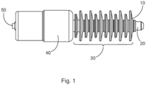
- Fig. 1 shows an outer view of the new vacuum-based fuse - CutOut device coated with embedding material
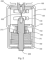
- Fig. 2 shows a cross section of the vacuum-based fuse - CutOut.
- the vacuum-based fuse - CutOut allows the required fuse functionality purely based on the melting of the fuse wire 220.
- the fuse wire can be inserted as shown in Fig. 1 and elongated in length by providing a hollow structure inside the contact and connection part, not shown here.
- Both shown contact parts 110 and 130 are used in case a short circuit interruption current must be done.
- Rated current interruption is possible even with only Buttcontacts.
- Due to the vacuum technology a high transient recovery voltage (TRV) can be accommodated, without the risk of failing current interruption at current zero. This means that the different required TRV values in the markets around the world can be met with the same new fuse.
- TRV transient recovery voltage
- the fuse-wire 220 will melts with a foreseeable melting characteristic.
- the rated- and short circuit current interruption is done in the gap distance between the contact 100 and 130. Only a slight movement of the so-called movable side (the contact 130 and/or the electrical connection rod 210) is needed to get the striker functionality to release the drop-out function of the fuse CutOut in case that will be needed.
- the fuse-wire can be supported by a steel wire which is installed in parallel to the fuse-wire 220 to keep the mechanically pre-loaded spring 180 in position and provide the potential energy to get the striker moving functionality.
- a movement inside the vacuum fuse 40 is facilitated using a membrane or a simple bellows 150; only one single operation is needed.
- the insulation and to keep the vacuum device sealed is given by the insulation part 120, to insulate for example the support lid 140 and the electrical connection rod 230 in case of current interruption.
- An outer insulation can be achieved by an over molding of the device using silicone 10 for example, as shown Fig. 1 . This provides the needed insulation distance to take the voltage while current interruption and providing corrosion protection as well. On or more parts, and indeed the full CutOut vacuum device 40, can be covered with the insulation material.
Landscapes
- Fuses (AREA)
Abstract
- a first electrical connection rod (230);
- a second electrical connection rod (210);
- a first contact (100);
- a second contact (130); and
- a fuse wire (220);
wherein the first contact is mounted to the first electrical connection rod;
wherein the second contact is mounted to the second electrical connection rod;
wherein when a current below a threshold levels flows through the vacuum-based fuse - CutOut or no current flows through the vacuum-based fuse - CutOut the vacuum-based fuse - CutOut is configured to hold the first contact a fixed distance from the second contact and the fuse wire is configured to electrical connect the first electrical connection rod to the second electrical connection rod; and
wherein when a current at or above the threshold flows through the vacuum-based fuse - CutOut the fuse wire is configured to electrically disconnect the first electrical connection rod from the second electrical connection rod.
Description
- The present invention relates to a Vacuum interrupter fuse, for low, medium, and high voltage use, also termed a CutOut fuse, that has in addition to the fuse characteristic a short circuit current interruption function.
- In electrical distribution, a fuse cutout or cut-out fuse (often referred to as a cutout) is a combination of a fuse and a switch, used in primary overhead feeder lines and taps to protect distribution networks (equipment like overhead lines, transformers etc.) in short circuit and overload situations. An overcurrent caused by a fault in the transformer or customer circuit will cause the fuse to melt and the switch mechanism to visibly open, disconnecting the transformer from the line. The device can also be opened manually by utility linemen standing on the ground and using a long insulating stick called a "hot stick".
- An expulsion fuse cutout consists of three major components:
- The cutout body, an open frame that supports the fuse holder and a ribbed porcelain or polymer insulator that electrically isolates the conductive portions of the assembly from the support to which the insulator is fastened.
- The fuse holder, also called the "fuse tube", an insulating tube which contains the replaceable fuse-link element. When the contained fuse-link melts ("blows in case of higher current loads"), it opens the circuit, and the fuse holder drops out of the upper contact and hangs from a hinge on its lower end. This hanging fuse holder provides a visible indication that the expulsion fuse has operated and assurance that the circuit is open. The circuit can also be opened manually by pulling out the fuse holder using a hot stick.
- The fuse element, or "fuse-link", is the replaceable portion of the assembly that melts and breaks (interrupts the current load) the circuit when the electric current through it exceeds its rated current value.
- The fuse-link elements used in most distribution CutOuts are mainly in tin or silver alloy wires that melt when subjected to high enough current. Ampere ratings of fuse-link elements typically vary from 1 ampere to 200 amperes.
- CutOuts are typically mounted about 20 degrees off vertical so that the center of gravity of the fuse holder is displaced and the fuse holder will rotate and fall open under its own weight when the expulsion fuse blows. Mechanical tension on the fuse-link normally holds an ejector spring in a stable position. When the fuse-link blows, the released spring pulls the pigtail of the fuse-link out of the fuse tube to enable to get interruption and to avoid damage to the transformer and fuse holder. This quenches any arc in the fuse tube.
- Each fuse tubes typically has an attached pull ring that can be engaged by a hook at the end of a fiberglass hot stick operated by a lineworker standing on the ground or from a bucket truck, to manually open the switch. While often used for switching, the standard CutOut shown is not designed to be manually opened under load. For applications where the switch is likely to be used to interrupt power manually, a "load break" version is available that has an attachment to quench the arc.
- Expulsion CutOut fuses are releasing gases produced by internal arcing results in current interruption. They utilize Aluminum Hydroxide to create the de-ionizing action needed to interrupt the current, to quench the arc.
- Presently fuse CutOut expulsion fuses are also mainly installed in current overhead lines to protect and provide safety in the network. Here the expulsion fuse can interrupt currents in the range of several ampere but are also able to interrupt higher load currents / short circuit currents up to several kA if needed.
- The current flow through the CutOut of an expulsion fuse is done using a fuse-link inside of a top side closed fuse tube and on the other side open fuse-tube arrangement. The fuse-tube is concentric oriented around the fuse-link.
- In the situation when the interruption of rated fuse current must be done, even up to several 100A, the load interruption takes place mainly inside the fuse-tube only (exposed to atmospheric air gas and pressure), because the quantity of plasma gases generated during the interruption must be released from the fuse-tube open side to the atmosphere, and this causes limitations in performance.
- In the situation where a short circuit current interruption must be done, the amount of plasma released is high and can cause a fire risk to components surrounding the expulsion fuse due to the expulsion of plasma, and the interruption is extremely loud.
- Furthermore, in an expulsion fuse as a consequence of interruption chemical components are released from the fuse-tube due to the desired and needed arc quenching and generation of plasma and interaction of that plasma with the inner wall. The interruption plasma is not only ejected but the plasma interacts with the inner layer of the fuse-tube, and consequently some chemically cracked components are also released from the fuse-tube into the atmosphere along with the plasma.
- There is a developing need in market sectors, already established in (California/USA) market segments, to avoid sparking and gas release to the environment from currently used expulsion CutOut fuses.
- Drawbacks of current devices is the plasma exhaust chemical components combined with a very noisy interruption. There are also limitations
based on dimension constrains to meet performance requirements (the possibility to withstand robust the transient recovery voltage (TRV) of more than 0,1 kV/µs while current interruption), and the expulsion fuses are costly as well. - There is a need to address these issues.
- Therefore, it would be advantageous to have an improved fuse - CutOut based on vacuum technology.
- The object of the present invention is solved with the subject matter of the independent claims, wherein further embodiments are incorporated in the dependent claims.
- In a first aspect, there is provided a vacuum-based fuse - CutOut device, comprising:
- a first electrical connection rod;
- a second electrical connection rod;
- a first contact;
- a second contact; and
- a fuse wire.
- The first contact is mounted to the first electrical connection rod. The second contact is mounted to the second electrical connection rod. When a current flows through the vacuum-based fuse - CutOut or no current flows through the vacuum-based fuse - CutOut. It is configured to hold the first contact a fixed distance from the second contact and the fuse - wire is configured to electrical connect the first electrical connection rod to the second electrical connection rod. When a current at or above the threshold flows through the vacuum-based fuse - CutOut the fuse wire is configured to electrically disconnect the first electrical connection rod from the second electrical connection rod.
- In an example, when the fuse wire electrically disconnects the first electrical connection rod from the second electrical connection rod the vacuum-based fuse - CutOut is configured to move the second contact away from the first contact.
- In an example, when the fuse wire electrically disconnects the first electrical connection rod from the second electrical connection rod the vacuum-based fuse - CutOut is configured to move the second electrical connection rod away from the first electrical connection rod.
- In an example, the second contact is fixedly mounted to the second electrical connection rod.
- In an example, the vacuum-based fuse - CutOut comprises a release spring, and when the fuse wire electrically disconnects the first electrical connection rod from the second electrical connection rod the release spring is configured to move the second contact away from the first contact.
- In an example, the first contact is a transverse magnetic field, TMF, contact, and the second contact is a TMF contact.
- In an example, the first contact is an axial magnetic field, AMF, contact, and the second contact is an AMF contact.
- In an example, the first contact is a transverse magnetic field, TMF, contact, and the second contact is an AMF contact.
- In an example, the first contact is an AMF contact, and the second contact is a TMF contact.
- In an example, the first contact is a hybrid contact with the known technology of AMF/TMF or TMF/AMF combination.
- In an example, the vacuum-based fuse - CutOut comprises a steel wire, and wherein when the current below the threshold levels flows through the vacuum-based fuse - CutOut or no current flows through the vacuum-based fuse - CutOut the first contact is held the fixed distance from the second contact at least in part by the steel wire.
- In an example, when the current below the threshold levels flows through the vacuum-based fuse - CutOut or no current flows through the vacuum-based fuse - CutOut the first contact is held the fixed distance from the second contact at least in part by the fuse wire.
- In an example, the vacuum-based fuse - CutOut comprises an outer body, and wherein the outer body is configured to maintain a vacuum within the body when the current below the threshold levels flows through the vacuum-based fuse - CutOut or no current flows through the vacuum-based fuse - CutOut.
- In an example, the vacuum-based fuse - CutOut comprises an insulation part located within the outer body, and the insulation part surrounds the first contact and the second contact when the current below the threshold levels flows through the vacuum-based fuse - CutOut or no current flows through the vacuum-based fuse - CutOut.
- In an example, the insulation part surrounds the first contact and the second contact during movement of the second contact away from the first contact when the fuse wire electrically disconnects the first electrical connection rod from the second electrical connection rod.
- In a second aspect, there is provided a vacuum interrupter device, comprising:
- a vacuum-based fuse - CutOut according to the first aspect;
- a first electrical connector connected to the first electrical connection rod of the vacuum-based fuse - CutOut;
- a second electrical connector connected to the second electrical connection rod of the vacuum-based fuse - CutOut; and
- at least one insulation structure surrounds at least part of the first electrical connector.
- The above aspects and examples will become apparent from and be elucidated with reference to the embodiments described hereinafter.
- Exemplary embodiments will be described in the following with reference to the following drawings:
-
Fig. 1 shows a complete vacuum-based fuse - CutOut device that has a vacuum interrupter fuse; and -
Fig. 2 shows more details of the vacuum-based fuse - CutOut as shown inFig. 1 . - As discussed above currently used expulsion fuse CutOut fuses have the advantage to interrupt load- or short circuit current. The clear drawback is the release of chemical components during load- and short circuit current interruption and the plasma flame to the surrounding which might be damage nearby components. In addition, and especially during the short circuit current interruption it's noisy and sounds like an explosion!
- Presently available current limiting fuses have full functionality but are bulky and the performance is quite limited and costly compared to the expulsion fuse CutOut device and can be close to a factor of 10 times higher in cost.
- To overcome these disadvantages a new vacuum-based fuse - CutOut and vacuum device having such a vacuum-based fuse - CutOut were developed.
-
Figs. 1-2 relate to the new vacuum-based fuse - CutOut and vacuum-based fuse - CutOut having such a vacuum fuse. - An exemplar vacuum-based fuse - CutOut 40 comprises:
- a first
electrical connection rod 230; - a second
electrical connection rod 210; - a
first contact 100; - a
second contact 130; and - a
fuse wire 220. - The first contact is mounted to the first electrical connection rod. The second contact is mounted to the second electrical connection rod. When a current below a threshold levels flows through the vacuum-based fuse - CutOut or no current flows through the vacuum-based fuse - CutOut the vacuum-based fuse - CutOut is configured to hold the first contact a fixed distance from the second contact and the fuse wire is configured to electrical connect the first electrical connection rod to the second electrical connection rod. When a current at or above the threshold flows through the vacuum-based fuse - CutOut the fuse wire is configured to electrically disconnect the first electrical connection rod from the second electrical connection rod.
- In an example, when the fuse wire electrically disconnects the first electrical connection rod from the second electrical connection rod the vacuum-based fuse - CutOut is configured to move the second contact away from the first contact.
- In an example, when the fuse wire electrically disconnects the first electrical connection rod from the second electrical connection rod the vacuum-based fuse - CutOut is configured to move the second electrical connection rod away from the first electrical connection rod.
- In an example, the second contact is fixedly mounted to the second electrical connection rod.
- In an example, the vacuum-based fuse - CutOut comprises a
release spring 180, and when the fuse wire electrically disconnects the first electrical connection rod from the second electrical connection rod the release spring is configured to move the second contact away from the first contact. - In an example, the first contact is a transverse magnetic field, TMF, contact, and the second contact is a TMF contact.
- In an example, the first contact is an axial magnetic field, AMF, contact, and the second contact is an AMF contact.
- In an example, the first contact is a transverse magnetic field, TMF, contact, and the second contact is an AMF contact.
- In an example, the first contact is an AMF contact, and the second contact is a TMF contact.
- In an example, there is hybrid contact installed with combination of AMF/TMF or TMF/TMF.
- In an example, the vacuum-based fuse - CutOut comprises a steel wire, and wherein when the current below the threshold levels flows through the vacuum-based fuse - CutOut or no current flows through the vacuum-based fuse - CutOut the first contact is held the fixed distance from the second contact at least in part by the steel wire.
- In an example, when the current below the threshold levels flows through the vacuum-based fuse - CutOut or no current flows through the vacuum-based fuse - CutOut the first contact is held the fixed distance from the second contact at least in part by the fuse wire.
- In an example, the vacuum-based fuse - CutOut comprises an
outer body 110, and the outer body is configured to maintain a vacuum within the body when the current below the threshold levels flows through the vacuum-based fuse - CutOut or no current flows through the vacuum-based fuse - CutOut. - In an example, the vacuum-based fuse - CutOut comprises an
insulation part 120 located within the outer body, and wherein the insulation part surrounds the first contact and the second contact when the current below the threshold levels flows through the vacuum-based fuse - CutOut or no current flows through the vacuum-based fuse - CutOut. - In an example, the insulation part surrounds the first contact and the second contact during movement of the second contact away from the first contact when the fuse wire electrically disconnects the first electrical connection rod from the second electrical connection rod.
- A complete vacuum-based fuse - CutOut comprises a vacuum-based fuse - CutOut 40 as described in any of the examples above. The device also comprises;
- a first
electrical connector 20 connected to the firstelectrical connection rod 230 of the vacuum-based fuse - CutOut; - a second
electrical connector 50 connected to the secondelectrical connection rod 210 of the vacuum-based fuse - CutOut; and - at least one
insulation structure electrical connector 20. - The new vacuum-based fuse - CutOut is described in specific detail below, where again reference is made to
Figs. 1-2 . - The inventors developed a new vacuum-based fuse - CutOut, that is a one time use vacuum device, which has two current carrying terminals inside the vacuum environment inside the vacuum device. The new vacuum-based fuse - CutOut has the function of a fuse CutOut and will be very similar in the function to an expulsion fuse CutOut.
- The new vacuum-based fuse - CutOut has the following functionally:
- The fuse wire will short circuit both installed contacts used in the vacuum device
- In case of fuse current interruption, the wire between both the contacts will melt when a threshold current is reached, and a spark or arc will occur between both the contacts and will be interrupted or quenched as well
- In the case of overcurrent interruption functionality, the "full-range" function is given because due to the vacuum insulation around the wire the fuse-wire will melt a bit above the rated fuse current and the full range characteristic will be achieved
- At short circuit current conditions, the fuse-wire instantly melts and the short circuit current is established / ignited and a vacuum arc is created. This arc is however steered, like in today's vacuum interrupter technology, between both contacts and finally be interrupted at current zero
- The arc will be kept inside the vacuum device, and after interruption the part (fuse wire) can be completely exchanged/replaced like the solutions we have today in current limiting fuse
- On one side of the device an elastic lid or a bellows is provided, which allows a movement of a pin to get a striker function: After the interruption of the fuse, a CutOut automatically drops out to show it's visible cut off operation and showing a separation / insulation distance
- The new technique provides a vacuum device, which has two transverse magnetic field (TMF) - Butt-, axial magnetic field (AMF) or hybrid (TMF-AMF) contacts with a fixed contact gap between the contact pair.
- A "fuse wire" is installed between the 2 x TMF contacts and/or on the electrical rods to which the contacts are mounted to let the current flow through the device. The wire is installed "freely" in the vacuum atmosphere or can be covered to achieve specific melting characteristics (known from standard fuse technology).
- Furthermore, a steel wire can be placed in addition to the fuse-wire to provide mechanical support from top side in situation when a spring force on the striker side is utilized to release mechanical excentre on CutOut mechanism, that aids in keeping the contacts at a fixed separation until the fuse-wire melts. The main advantage is the comparable low cost of such a technology, with the providing of a "green" and safe interruption, with no sparking and no gas or plasma release to the environment. Furthermore, the noise while interruption is quite limited and silent.
- Because of the superior dielectric behaviour of the interruption device, the part as such can be small. The dielectrically performance in air (or the surrounding atmosphere) is being provided by an insulation material, like silicone or other outdoor material. To have a corrosion protection and UV - light resistance this material can be applied to elongate the creepage length and to avoid flashover along the interruption device at the time of load or short circuit interruption.
-
Fig. 1 shows an outer view of the new vacuum-based fuse - CutOut device coated with embedding material, andFig. 2 shows a cross section of the vacuum-based fuse - CutOut. - The vacuum-based fuse - CutOut allows the required fuse functionality purely based on the melting of the
fuse wire 220. The fuse wire can be inserted as shown inFig. 1 and elongated in length by providing a hollow structure inside the contact and connection part, not shown here. - Both shown
contact parts - In the situation when interruption is required, the fuse-
wire 220 will melts with a foreseeable melting characteristic. The rated- and short circuit current interruption is done in the gap distance between thecontact contact 130 and/or the electrical connection rod 210) is needed to get the striker functionality to release the drop-out function of the fuse CutOut in case that will be needed. The fuse-wire can be supported by a steel wire which is installed in parallel to the fuse-wire 220 to keep the mechanicallypre-loaded spring 180 in position and provide the potential energy to get the striker moving functionality. - To get a certain movement for the striker a movement inside the vacuum fuse 40 is facilitated using a membrane or a simple bellows 150; only one single operation is needed. The insulation and to keep the vacuum device sealed is given by the
insulation part 120, to insulate for example thesupport lid 140 and theelectrical connection rod 230 in case of current interruption. - An outer insulation can be achieved by an over molding of the
device using silicone 10 for example, as shownFig. 1 . This provides the needed insulation distance to take the voltage while current interruption and providing corrosion protection as well. On or more parts, and indeed the full CutOut vacuum device 40, can be covered with the insulation material. - In summary the following advantages are provided by the new vacuum-based fuse - CutOut:
- Spark-free and a so-called green current interruption technology
- Low cost for the device based on the well-developed vacuum technology
- Use of known TMF/AMF or hybrid contact(s)
- Less type testing required based on vacuum technology steep TRV requirements will be taken easily
- Number of required variants can be limited because the TRV needs can be covered based on the vacuum technology via smaller number of variants
- Specific high short circuit interruption performance - less volume needed - dimensions comparable low
- Dimensions can fit to today's CutOut holder and mechanism and the electrical insulation for each rating, and can be smaller than today's technology
- The following reference numerals are:
- 10 Outer insulation material or surrounding insulation
- 20 Electrical connection rod, or connector, one side of connection to the CutOut current connection circuit
- 30 Insulation structures with creepage ribs
- 40 Vacuum-based fuse - CutOut in the current loop
- 50 Electrical connection rod, or connector, the side with striker to release the CutOut mechanism to get drop out functionality
- 100 Contact disc TMF type (as one possibility), fixed side
- 110 Outer insulation material or surrounding insulation, shown silicone coated/embedded
- 120 Vacuum ceramic cylinder / insulation device
- 130 Contact disc TMF type, slightly moving side to get striker functionality to release drop out function, (drop out function as per today's technology)
- 140 Support and lid part of vacuum device
- 150 Flexible elements to allow limited movement, striker function (shown bellows) but can be also an elastic membrane
- 160 Support lid to cover the components
- 170 Bellows connection part or membrane to allow movement for striker functionality
- 180 Release spring to operate striker after current interruption
- 190 Connection part to support / fixation of the release spring
- 200 Electrical connection rod with movement to allow striking function
- 210 Electrical connection rod made of copper or another conductive material
- 220 Fuse wire / and if needed in addition steel wire
- 230 Electrical connection rod
Claims (15)
- A vacuum-based fuse - CutOut (40), comprising:- a first electrical connection rod (230);- a second electrical connection rod (210);- a first contact (100);- a second contact (130); and- a fuse wire (220);wherein the first contact is mounted to the first electrical connection rod;wherein the second contact is mounted to the second electrical connection rod;wherein when a current below a threshold levels flows through the vacuum-based fuse - CutOut or no current flows through the vacuum-based fuse - CutOut the vacuum-based fuse - CutOut is configured to hold the first contact a fixed distance from the second contact and the fuse wire is configured to electrical connect the first electrical connection rod to the second electrical connection rod; andwherein when a current at or above the threshold flows through the vacuum-based fuse - CutOut the fuse wire is configured to electrically disconnect the first electrical connection rod from the second electrical connection rod.
- Vacuum-based fuse - CutOut according to claim 1, wherein when the fuse wire electrically disconnects the first electrical connection rod from the second electrical connection rod the vacuum-based fuse - CutOut is configured to move the second contact away from the first contact.
- Vacuum-based fuse - CutOut according to claim 2, wherein when the fuse wire electrically disconnects the first electrical connection rod from the second electrical connection rod the vacuum-based fuse - CutOut is configured to move the second electrical connection rod away from the first electrical connection rod.
- Vacuum-based fuse - CutOut according to any of claims 2-3, wherein the second contact is fixedly mounted to the second electrical connection rod.
- Vacuum-based fuse - CutOut according to any of claims 2-4, wherein the vacuum-based fuse - CutOut comprises a release spring (180), and wherein when the fuse wire electrically disconnects the first electrical connection rod from the second electrical connection rod the release spring is configured to move the second contact away from the first contact.
- Vacuum-based fuse - CutOut according to any of claims 1-5, wherein the first contact is a transverse magnetic field, TMF, contact, and wherein the second contact is a TMF contact.
- Vacuum-based fuse - CutOut according to any of claims 1-5, wherein the first contact is an axial magnetic field, AMF, contact, and wherein the second contact is an AMF contact.
- Vacuum-based fuse - CutOut according to any of claims 1-5, wherein the first contact is a transverse magnetic field, TMF, contact, and wherein the second contact is an AMF contact.
- Vacuum-based fuse - CutOut according to any of claims 1-5, wherein the first contact is an AMF contact, and wherein the second contact is a TMF contact.
- Vacuum-based fuse - CutOut according to any of claims 1-9, wherein the vacuum-based fuse - CutOut comprises a steel wire, and wherein when the current below the threshold levels flows through the vacuum-based fuse - CutOut or no current flows through the vacuum-based fuse - CutOut the first contact is held the fixed distance from the second contact at least in part by the steel wire.
- Vacuum-based fuse - CutOut according to any of claims 1-10, wherein when the current below the threshold levels flows through the vacuum-based fuse - CutOut or no current flows through the vacuum-based fuse - CutOut the first contact is held the fixed distance from the second contact at least in part by the fuse wire.
- Vacuum-based fuse - CutOut according to any of claims 1-11, wherein the vacuum-based fuse - CutOut comprises an outer body (110), and wherein the outer body is configured to maintain a vacuum within the body when the current below the threshold levels flows through the vacuum-based fuse - CutOut or no current flows through the vacuum-based fuse - CutOut.
- Vacuum-based fuse - CutOut according to claim 12, wherein the vacuum-based fuse - CutOut comprises an insulation part (120) located within the outer body, and wherein the insulation part surrounds the first contact and the second contact when the current below the threshold levels flows through the vacuum-based fuse - CutOut or no current flows through the vacuum-based fuse - CutOut.
- Vacuum-based fuse - CutOut according to claim 13, wherein the insulation part surrounds the first contact and the second contact during movement of the second contact away from the first contact when the fuse wire electrically disconnects the first electrical connection rod from the second electrical connection rod.
- A vacuum interrupter device, comprising:- a vacuum-based fuse - CutOut according to any of claims 1-14;- a first electrical connector (20) connected to the first electrical connection rod of the vacuum-based fuse - CutOut;- a second electrical connector (50) connected to the second electrical connection rod of the vacuum-based fuse - CutOut; and- at least one insulation structure (10, 30) surround at least part of the first electrical connector (20).
Priority Applications (3)
| Application Number | Priority Date | Filing Date | Title |
|---|---|---|---|
| EP23151172.6A EP4401107A1 (en) | 2023-01-11 | 2023-01-11 | Vacuum interrupter fuse |
| US18/408,844 US20240234068A1 (en) | 2023-01-11 | 2024-01-10 | Vacuum Interrupter Fuse |
| CN202410033969.2A CN118335577A (en) | 2023-01-11 | 2024-01-10 | Vacuum interrupter fuse |
Applications Claiming Priority (1)
| Application Number | Priority Date | Filing Date | Title |
|---|---|---|---|
| EP23151172.6A EP4401107A1 (en) | 2023-01-11 | 2023-01-11 | Vacuum interrupter fuse |
Publications (1)
| Publication Number | Publication Date |
|---|---|
| EP4401107A1 true EP4401107A1 (en) | 2024-07-17 |
Family
ID=84923101
Family Applications (1)
| Application Number | Title | Priority Date | Filing Date |
|---|---|---|---|
| EP23151172.6A Pending EP4401107A1 (en) | 2023-01-11 | 2023-01-11 | Vacuum interrupter fuse |
Country Status (3)
| Country | Link |
|---|---|
| US (1) | US20240234068A1 (en) |
| EP (1) | EP4401107A1 (en) |
| CN (1) | CN118335577A (en) |
Citations (6)
| Publication number | Priority date | Publication date | Assignee | Title |
|---|---|---|---|---|
| US3510819A (en) * | 1968-05-13 | 1970-05-05 | Gen Electric | Vacuum fuse and method of making same |
| US3898602A (en) * | 1974-01-25 | 1975-08-05 | Itt | Enclosed, non-vented expulsion fuse |
| US3909765A (en) * | 1971-10-21 | 1975-09-30 | Rte Corp | Fused vacuum interrupter |
| DE2822773A1 (en) * | 1978-05-24 | 1979-11-29 | Siemens Ag | Fuse link in vacuum housing - forms part of plug connector for medium voltage installations with short link generating small amount of heat |
| EP0210778A2 (en) * | 1985-07-20 | 1987-02-04 | Y.S. Securities Limited | Fuse for an alternating current power circuit |
| US4713644A (en) * | 1986-10-14 | 1987-12-15 | Cooper Industries, Inc. | Vacuum fuse |
Family Cites Families (10)
| Publication number | Priority date | Publication date | Assignee | Title |
|---|---|---|---|---|
| US2145375A (en) * | 1936-11-20 | 1939-01-31 | Line Material Co | Fuse construction |
| US2918551A (en) * | 1958-11-21 | 1959-12-22 | Chase Shawmut Co | Fuses with built-in indicating plungers |
| US3113193A (en) * | 1962-04-26 | 1963-12-03 | Chase Shawmut Co | Electric striker pin fuses for elevated circuit voltages |
| AU411764B2 (en) * | 1968-01-30 | 1971-03-23 | Dickson Primer Indus Triespty. Limited | Electric fuse-link, particularly for outdoor use |
| US3686604A (en) * | 1969-08-12 | 1972-08-22 | Rte Corp | Current interrupting safe break terminator |
| US4272751A (en) * | 1979-06-25 | 1981-06-09 | S&C Electric Company | High-voltage fuse link and method of manufacturing same |
| US4945333A (en) * | 1989-02-13 | 1990-07-31 | Asea Brown Boveri Inc. | Fuse assembly, for a cutout, with accelerated arc extinction |
| US7781694B2 (en) * | 2007-06-05 | 2010-08-24 | Cooper Technologies Company | Vacuum fault interrupter |
| US8497446B1 (en) * | 2011-01-24 | 2013-07-30 | Michael David Glaser | Encapsulated vacuum interrupter with grounded end cup and drive rod |
| US9490093B2 (en) * | 2013-07-12 | 2016-11-08 | Eaton Corporation | Fuse and trip mechanism therefor |
-
2023
- 2023-01-11 EP EP23151172.6A patent/EP4401107A1/en active Pending
-
2024
- 2024-01-10 US US18/408,844 patent/US20240234068A1/en active Pending
- 2024-01-10 CN CN202410033969.2A patent/CN118335577A/en active Pending
Patent Citations (6)
| Publication number | Priority date | Publication date | Assignee | Title |
|---|---|---|---|---|
| US3510819A (en) * | 1968-05-13 | 1970-05-05 | Gen Electric | Vacuum fuse and method of making same |
| US3909765A (en) * | 1971-10-21 | 1975-09-30 | Rte Corp | Fused vacuum interrupter |
| US3898602A (en) * | 1974-01-25 | 1975-08-05 | Itt | Enclosed, non-vented expulsion fuse |
| DE2822773A1 (en) * | 1978-05-24 | 1979-11-29 | Siemens Ag | Fuse link in vacuum housing - forms part of plug connector for medium voltage installations with short link generating small amount of heat |
| EP0210778A2 (en) * | 1985-07-20 | 1987-02-04 | Y.S. Securities Limited | Fuse for an alternating current power circuit |
| US4713644A (en) * | 1986-10-14 | 1987-12-15 | Cooper Industries, Inc. | Vacuum fuse |
Non-Patent Citations (1)
| Title |
|---|
| LAMARA TAREK ET AL: "Theoretical and Experimental Investigation of New Innovative TMF-AMF Contacts for High-Current Vacuum Arc Interrup", IEEE TRANSACTIONS ON PLASMA SCIENCE, IEEE SERVICE CENTER, PISCATAWAY, NJ, US, vol. 41, no. 8, 1 August 2013 (2013-08-01), pages 2043 - 2050, XP011523369, ISSN: 0093-3813, [retrieved on 20130807], DOI: 10.1109/TPS.2013.2273178 * |
Also Published As
| Publication number | Publication date |
|---|---|
| US20240234068A1 (en) | 2024-07-11 |
| CN118335577A (en) | 2024-07-12 |
Similar Documents
| Publication | Publication Date | Title |
|---|---|---|
| US5355111A (en) | Nested contact and cap assembly for fuseholder | |
| EP0660351B1 (en) | Improved current limiting fuse and dropout fuseholder | |
| CN101521128B (en) | Device for protecting against voltage surges comprising selective disconnection means | |
| US8004377B2 (en) | Indicator for a fault interrupter and load break switch | |
| US7936541B2 (en) | Adjustable rating for a fault interrupter and load break switch | |
| US4742323A (en) | Fuse for an alternating current power circuit | |
| US4184138A (en) | Offset, series connected current limiting fuse and expulsion fuseholder assembly for opengate cutout | |
| US20090277768A1 (en) | Low Oil Trip Assembly for a Fault Interrupter and Load Break Switch | |
| JPS6153813B2 (en) | ||
| CN1245342A (en) | Submersible transformer using device with circuit braker and fuse for self-protecting | |
| CN101889375B (en) | Surge arrester having thermal overload protection | |
| EP4401107A1 (en) | Vacuum interrupter fuse | |
| US3309477A (en) | Protective means for encased electrical apparatus | |
| GB1559872A (en) | Current limiting fuse device for relatively high curren | |
| US12051555B2 (en) | Use of a HV HRC fuse for a drop-out fuse system | |
| CN113366599B (en) | A method of using a fuse for direct current transmission | |
| US2424126A (en) | Electric circuit breaker | |
| Mikulecky | Current-limiting fuse with full-range clearing ability | |
| SU1092603A2 (en) | Disconnecting safety device | |
| CN108630508A (en) | A kind of high pressure enclosed type expulsion fuse | |
| US3254182A (en) | Fuse constructions including stress reducing means | |
| JPH01267982A (en) | Lightening arrester | |
| JPH0660227U (en) | Gas insulated switchgear grounding device | |
| JPH03285285A (en) | Separator of lightning arrestor |
Legal Events
| Date | Code | Title | Description |
|---|---|---|---|
| PUAI | Public reference made under article 153(3) epc to a published international application that has entered the european phase |
Free format text: ORIGINAL CODE: 0009012 |
|
| STAA | Information on the status of an ep patent application or granted ep patent |
Free format text: STATUS: THE APPLICATION HAS BEEN PUBLISHED |
|
| AK | Designated contracting states |
Kind code of ref document: A1 Designated state(s): AL AT BE BG CH CY CZ DE DK EE ES FI FR GB GR HR HU IE IS IT LI LT LU LV MC ME MK MT NL NO PL PT RO RS SE SI SK SM TR |
|
| STAA | Information on the status of an ep patent application or granted ep patent |
Free format text: STATUS: REQUEST FOR EXAMINATION WAS MADE |
|
| 17P | Request for examination filed |
Effective date: 20250116 |
|
| STAA | Information on the status of an ep patent application or granted ep patent |
Free format text: STATUS: EXAMINATION IS IN PROGRESS |
|
| 17Q | First examination report despatched |
Effective date: 20260330 |