EP4400920A1 - A method for calibrating feedback gains of an lqi controller - Google Patents
A method for calibrating feedback gains of an lqi controller Download PDFInfo
- Publication number
- EP4400920A1 EP4400920A1 EP23151473.8A EP23151473A EP4400920A1 EP 4400920 A1 EP4400920 A1 EP 4400920A1 EP 23151473 A EP23151473 A EP 23151473A EP 4400920 A1 EP4400920 A1 EP 4400920A1
- Authority
- EP
- European Patent Office
- Prior art keywords
- matrix
- physical
- terms
- aug
- controller
- Prior art date
- Legal status (The legal status is an assumption and is not a legal conclusion. Google has not performed a legal analysis and makes no representation as to the accuracy of the status listed.)
- Pending
Links
Images




Classifications
-
- B—PERFORMING OPERATIONS; TRANSPORTING
- B60—VEHICLES IN GENERAL
- B60W—CONJOINT CONTROL OF VEHICLE SUB-UNITS OF DIFFERENT TYPE OR DIFFERENT FUNCTION; CONTROL SYSTEMS SPECIALLY ADAPTED FOR HYBRID VEHICLES; ROAD VEHICLE DRIVE CONTROL SYSTEMS FOR PURPOSES NOT RELATED TO THE CONTROL OF A PARTICULAR SUB-UNIT
- B60W20/00—Control systems specially adapted for hybrid vehicles
- B60W20/40—Controlling the engagement or disengagement of prime movers, e.g. for transition between prime movers
-
- G—PHYSICS
- G05—CONTROLLING; REGULATING
- G05B—CONTROL OR REGULATING SYSTEMS IN GENERAL; FUNCTIONAL ELEMENTS OF SUCH SYSTEMS; MONITORING OR TESTING ARRANGEMENTS FOR SUCH SYSTEMS OR ELEMENTS
- G05B13/00—Adaptive control systems, i.e. systems automatically adjusting themselves to have a performance which is optimum according to some preassigned criterion
- G05B13/02—Adaptive control systems, i.e. systems automatically adjusting themselves to have a performance which is optimum according to some preassigned criterion electric
- G05B13/04—Adaptive control systems, i.e. systems automatically adjusting themselves to have a performance which is optimum according to some preassigned criterion electric involving the use of models or simulators
- G05B13/048—Adaptive control systems, i.e. systems automatically adjusting themselves to have a performance which is optimum according to some preassigned criterion electric involving the use of models or simulators using a predictor
-
- B—PERFORMING OPERATIONS; TRANSPORTING
- B60—VEHICLES IN GENERAL
- B60K—ARRANGEMENT OR MOUNTING OF PROPULSION UNITS OR OF TRANSMISSIONS IN VEHICLES; ARRANGEMENT OR MOUNTING OF PLURAL DIVERSE PRIME-MOVERS IN VEHICLES; AUXILIARY DRIVES FOR VEHICLES; INSTRUMENTATION OR DASHBOARDS FOR VEHICLES; ARRANGEMENTS IN CONNECTION WITH COOLING, AIR INTAKE, GAS EXHAUST OR FUEL SUPPLY OF PROPULSION UNITS IN VEHICLES
- B60K6/00—Arrangement or mounting of plural diverse prime-movers for mutual or common propulsion, e.g. hybrid propulsion systems comprising electric motors and internal combustion engines
- B60K6/20—Arrangement or mounting of plural diverse prime-movers for mutual or common propulsion, e.g. hybrid propulsion systems comprising electric motors and internal combustion engines the prime-movers consisting of electric motors and internal combustion engines, e.g. HEVs
- B60K6/22—Arrangement or mounting of plural diverse prime-movers for mutual or common propulsion, e.g. hybrid propulsion systems comprising electric motors and internal combustion engines the prime-movers consisting of electric motors and internal combustion engines, e.g. HEVs characterised by apparatus, components or means specially adapted for HEVs
- B60K6/24—Arrangement or mounting of plural diverse prime-movers for mutual or common propulsion, e.g. hybrid propulsion systems comprising electric motors and internal combustion engines the prime-movers consisting of electric motors and internal combustion engines, e.g. HEVs characterised by apparatus, components or means specially adapted for HEVs characterised by the combustion engines
-
- B—PERFORMING OPERATIONS; TRANSPORTING
- B60—VEHICLES IN GENERAL
- B60K—ARRANGEMENT OR MOUNTING OF PROPULSION UNITS OR OF TRANSMISSIONS IN VEHICLES; ARRANGEMENT OR MOUNTING OF PLURAL DIVERSE PRIME-MOVERS IN VEHICLES; AUXILIARY DRIVES FOR VEHICLES; INSTRUMENTATION OR DASHBOARDS FOR VEHICLES; ARRANGEMENTS IN CONNECTION WITH COOLING, AIR INTAKE, GAS EXHAUST OR FUEL SUPPLY OF PROPULSION UNITS IN VEHICLES
- B60K6/00—Arrangement or mounting of plural diverse prime-movers for mutual or common propulsion, e.g. hybrid propulsion systems comprising electric motors and internal combustion engines
- B60K6/20—Arrangement or mounting of plural diverse prime-movers for mutual or common propulsion, e.g. hybrid propulsion systems comprising electric motors and internal combustion engines the prime-movers consisting of electric motors and internal combustion engines, e.g. HEVs
- B60K6/22—Arrangement or mounting of plural diverse prime-movers for mutual or common propulsion, e.g. hybrid propulsion systems comprising electric motors and internal combustion engines the prime-movers consisting of electric motors and internal combustion engines, e.g. HEVs characterised by apparatus, components or means specially adapted for HEVs
- B60K6/26—Arrangement or mounting of plural diverse prime-movers for mutual or common propulsion, e.g. hybrid propulsion systems comprising electric motors and internal combustion engines the prime-movers consisting of electric motors and internal combustion engines, e.g. HEVs characterised by apparatus, components or means specially adapted for HEVs characterised by the motors or the generators
-
- B—PERFORMING OPERATIONS; TRANSPORTING
- B60—VEHICLES IN GENERAL
- B60K—ARRANGEMENT OR MOUNTING OF PROPULSION UNITS OR OF TRANSMISSIONS IN VEHICLES; ARRANGEMENT OR MOUNTING OF PLURAL DIVERSE PRIME-MOVERS IN VEHICLES; AUXILIARY DRIVES FOR VEHICLES; INSTRUMENTATION OR DASHBOARDS FOR VEHICLES; ARRANGEMENTS IN CONNECTION WITH COOLING, AIR INTAKE, GAS EXHAUST OR FUEL SUPPLY OF PROPULSION UNITS IN VEHICLES
- B60K6/00—Arrangement or mounting of plural diverse prime-movers for mutual or common propulsion, e.g. hybrid propulsion systems comprising electric motors and internal combustion engines
- B60K6/20—Arrangement or mounting of plural diverse prime-movers for mutual or common propulsion, e.g. hybrid propulsion systems comprising electric motors and internal combustion engines the prime-movers consisting of electric motors and internal combustion engines, e.g. HEVs
- B60K6/22—Arrangement or mounting of plural diverse prime-movers for mutual or common propulsion, e.g. hybrid propulsion systems comprising electric motors and internal combustion engines the prime-movers consisting of electric motors and internal combustion engines, e.g. HEVs characterised by apparatus, components or means specially adapted for HEVs
- B60K6/38—Arrangement or mounting of plural diverse prime-movers for mutual or common propulsion, e.g. hybrid propulsion systems comprising electric motors and internal combustion engines the prime-movers consisting of electric motors and internal combustion engines, e.g. HEVs characterised by apparatus, components or means specially adapted for HEVs characterised by the driveline clutches
- B60K6/387—Actuated clutches, i.e. clutches engaged or disengaged by electric, hydraulic or mechanical actuating means
-
- B—PERFORMING OPERATIONS; TRANSPORTING
- B60—VEHICLES IN GENERAL
- B60K—ARRANGEMENT OR MOUNTING OF PROPULSION UNITS OR OF TRANSMISSIONS IN VEHICLES; ARRANGEMENT OR MOUNTING OF PLURAL DIVERSE PRIME-MOVERS IN VEHICLES; AUXILIARY DRIVES FOR VEHICLES; INSTRUMENTATION OR DASHBOARDS FOR VEHICLES; ARRANGEMENTS IN CONNECTION WITH COOLING, AIR INTAKE, GAS EXHAUST OR FUEL SUPPLY OF PROPULSION UNITS IN VEHICLES
- B60K6/00—Arrangement or mounting of plural diverse prime-movers for mutual or common propulsion, e.g. hybrid propulsion systems comprising electric motors and internal combustion engines
- B60K6/20—Arrangement or mounting of plural diverse prime-movers for mutual or common propulsion, e.g. hybrid propulsion systems comprising electric motors and internal combustion engines the prime-movers consisting of electric motors and internal combustion engines, e.g. HEVs
- B60K6/42—Arrangement or mounting of plural diverse prime-movers for mutual or common propulsion, e.g. hybrid propulsion systems comprising electric motors and internal combustion engines the prime-movers consisting of electric motors and internal combustion engines, e.g. HEVs characterised by the architecture of the hybrid electric vehicle
- B60K6/44—Series-parallel type
- B60K6/442—Series-parallel switching type
-
- B—PERFORMING OPERATIONS; TRANSPORTING
- B60—VEHICLES IN GENERAL
- B60W—CONJOINT CONTROL OF VEHICLE SUB-UNITS OF DIFFERENT TYPE OR DIFFERENT FUNCTION; CONTROL SYSTEMS SPECIALLY ADAPTED FOR HYBRID VEHICLES; ROAD VEHICLE DRIVE CONTROL SYSTEMS FOR PURPOSES NOT RELATED TO THE CONTROL OF A PARTICULAR SUB-UNIT
- B60W10/00—Conjoint control of vehicle sub-units of different type or different function
- B60W10/02—Conjoint control of vehicle sub-units of different type or different function including control of driveline clutches
-
- B—PERFORMING OPERATIONS; TRANSPORTING
- B60—VEHICLES IN GENERAL
- B60W—CONJOINT CONTROL OF VEHICLE SUB-UNITS OF DIFFERENT TYPE OR DIFFERENT FUNCTION; CONTROL SYSTEMS SPECIALLY ADAPTED FOR HYBRID VEHICLES; ROAD VEHICLE DRIVE CONTROL SYSTEMS FOR PURPOSES NOT RELATED TO THE CONTROL OF A PARTICULAR SUB-UNIT
- B60W10/00—Conjoint control of vehicle sub-units of different type or different function
- B60W10/04—Conjoint control of vehicle sub-units of different type or different function including control of propulsion units
- B60W10/06—Conjoint control of vehicle sub-units of different type or different function including control of propulsion units including control of combustion engines
-
- B—PERFORMING OPERATIONS; TRANSPORTING
- B60—VEHICLES IN GENERAL
- B60W—CONJOINT CONTROL OF VEHICLE SUB-UNITS OF DIFFERENT TYPE OR DIFFERENT FUNCTION; CONTROL SYSTEMS SPECIALLY ADAPTED FOR HYBRID VEHICLES; ROAD VEHICLE DRIVE CONTROL SYSTEMS FOR PURPOSES NOT RELATED TO THE CONTROL OF A PARTICULAR SUB-UNIT
- B60W10/00—Conjoint control of vehicle sub-units of different type or different function
- B60W10/04—Conjoint control of vehicle sub-units of different type or different function including control of propulsion units
- B60W10/08—Conjoint control of vehicle sub-units of different type or different function including control of propulsion units including control of electric propulsion units, e.g. motors or generators
-
- B—PERFORMING OPERATIONS; TRANSPORTING
- B60—VEHICLES IN GENERAL
- B60W—CONJOINT CONTROL OF VEHICLE SUB-UNITS OF DIFFERENT TYPE OR DIFFERENT FUNCTION; CONTROL SYSTEMS SPECIALLY ADAPTED FOR HYBRID VEHICLES; ROAD VEHICLE DRIVE CONTROL SYSTEMS FOR PURPOSES NOT RELATED TO THE CONTROL OF A PARTICULAR SUB-UNIT
- B60W20/00—Control systems specially adapted for hybrid vehicles
- B60W20/10—Controlling the power contribution of each of the prime movers to meet required power demand
- B60W20/15—Control strategies specially adapted for achieving a particular effect
- B60W20/17—Control strategies specially adapted for achieving a particular effect for noise reduction
-
- B—PERFORMING OPERATIONS; TRANSPORTING
- B60—VEHICLES IN GENERAL
- B60W—CONJOINT CONTROL OF VEHICLE SUB-UNITS OF DIFFERENT TYPE OR DIFFERENT FUNCTION; CONTROL SYSTEMS SPECIALLY ADAPTED FOR HYBRID VEHICLES; ROAD VEHICLE DRIVE CONTROL SYSTEMS FOR PURPOSES NOT RELATED TO THE CONTROL OF A PARTICULAR SUB-UNIT
- B60W50/00—Details of control systems for road vehicle drive control not related to the control of a particular sub-unit, e.g. process diagnostic or vehicle driver interfaces
- B60W50/0098—Details of control systems ensuring comfort, safety or stability not otherwise provided for
-
- B—PERFORMING OPERATIONS; TRANSPORTING
- B60—VEHICLES IN GENERAL
- B60W—CONJOINT CONTROL OF VEHICLE SUB-UNITS OF DIFFERENT TYPE OR DIFFERENT FUNCTION; CONTROL SYSTEMS SPECIALLY ADAPTED FOR HYBRID VEHICLES; ROAD VEHICLE DRIVE CONTROL SYSTEMS FOR PURPOSES NOT RELATED TO THE CONTROL OF A PARTICULAR SUB-UNIT
- B60W50/00—Details of control systems for road vehicle drive control not related to the control of a particular sub-unit, e.g. process diagnostic or vehicle driver interfaces
- B60W2050/0001—Details of the control system
- B60W2050/0002—Automatic control, details of type of controller or control system architecture
- B60W2050/0008—Feedback, closed loop systems or details of feedback error signal
-
- B—PERFORMING OPERATIONS; TRANSPORTING
- B60—VEHICLES IN GENERAL
- B60W—CONJOINT CONTROL OF VEHICLE SUB-UNITS OF DIFFERENT TYPE OR DIFFERENT FUNCTION; CONTROL SYSTEMS SPECIALLY ADAPTED FOR HYBRID VEHICLES; ROAD VEHICLE DRIVE CONTROL SYSTEMS FOR PURPOSES NOT RELATED TO THE CONTROL OF A PARTICULAR SUB-UNIT
- B60W50/00—Details of control systems for road vehicle drive control not related to the control of a particular sub-unit, e.g. process diagnostic or vehicle driver interfaces
- B60W2050/0001—Details of the control system
- B60W2050/0019—Control system elements or transfer functions
- B60W2050/0022—Gains, weighting coefficients or weighting functions
-
- B—PERFORMING OPERATIONS; TRANSPORTING
- B60—VEHICLES IN GENERAL
- B60W—CONJOINT CONTROL OF VEHICLE SUB-UNITS OF DIFFERENT TYPE OR DIFFERENT FUNCTION; CONTROL SYSTEMS SPECIALLY ADAPTED FOR HYBRID VEHICLES; ROAD VEHICLE DRIVE CONTROL SYSTEMS FOR PURPOSES NOT RELATED TO THE CONTROL OF A PARTICULAR SUB-UNIT
- B60W50/00—Details of control systems for road vehicle drive control not related to the control of a particular sub-unit, e.g. process diagnostic or vehicle driver interfaces
- B60W2050/0001—Details of the control system
- B60W2050/0019—Control system elements or transfer functions
- B60W2050/0022—Gains, weighting coefficients or weighting functions
- B60W2050/0024—Variable gains
-
- B—PERFORMING OPERATIONS; TRANSPORTING
- B60—VEHICLES IN GENERAL
- B60W—CONJOINT CONTROL OF VEHICLE SUB-UNITS OF DIFFERENT TYPE OR DIFFERENT FUNCTION; CONTROL SYSTEMS SPECIALLY ADAPTED FOR HYBRID VEHICLES; ROAD VEHICLE DRIVE CONTROL SYSTEMS FOR PURPOSES NOT RELATED TO THE CONTROL OF A PARTICULAR SUB-UNIT
- B60W50/00—Details of control systems for road vehicle drive control not related to the control of a particular sub-unit, e.g. process diagnostic or vehicle driver interfaces
- B60W2050/0001—Details of the control system
- B60W2050/0019—Control system elements or transfer functions
- B60W2050/0028—Mathematical models, e.g. for simulation
-
- B—PERFORMING OPERATIONS; TRANSPORTING
- B60—VEHICLES IN GENERAL
- B60W—CONJOINT CONTROL OF VEHICLE SUB-UNITS OF DIFFERENT TYPE OR DIFFERENT FUNCTION; CONTROL SYSTEMS SPECIALLY ADAPTED FOR HYBRID VEHICLES; ROAD VEHICLE DRIVE CONTROL SYSTEMS FOR PURPOSES NOT RELATED TO THE CONTROL OF A PARTICULAR SUB-UNIT
- B60W50/00—Details of control systems for road vehicle drive control not related to the control of a particular sub-unit, e.g. process diagnostic or vehicle driver interfaces
- B60W2050/0001—Details of the control system
- B60W2050/0019—Control system elements or transfer functions
- B60W2050/0028—Mathematical models, e.g. for simulation
- B60W2050/0037—Mathematical models of vehicle sub-units
-
- B—PERFORMING OPERATIONS; TRANSPORTING
- B60—VEHICLES IN GENERAL
- B60W—CONJOINT CONTROL OF VEHICLE SUB-UNITS OF DIFFERENT TYPE OR DIFFERENT FUNCTION; CONTROL SYSTEMS SPECIALLY ADAPTED FOR HYBRID VEHICLES; ROAD VEHICLE DRIVE CONTROL SYSTEMS FOR PURPOSES NOT RELATED TO THE CONTROL OF A PARTICULAR SUB-UNIT
- B60W50/00—Details of control systems for road vehicle drive control not related to the control of a particular sub-unit, e.g. process diagnostic or vehicle driver interfaces
- B60W2050/0062—Adapting control system settings
- B60W2050/0075—Automatic parameter input, automatic initialising or calibrating means
- B60W2050/0083—Setting, resetting, calibration
- B60W2050/0088—Adaptive recalibration
-
- B—PERFORMING OPERATIONS; TRANSPORTING
- B60—VEHICLES IN GENERAL
- B60W—CONJOINT CONTROL OF VEHICLE SUB-UNITS OF DIFFERENT TYPE OR DIFFERENT FUNCTION; CONTROL SYSTEMS SPECIALLY ADAPTED FOR HYBRID VEHICLES; ROAD VEHICLE DRIVE CONTROL SYSTEMS FOR PURPOSES NOT RELATED TO THE CONTROL OF A PARTICULAR SUB-UNIT
- B60W2510/00—Input parameters relating to a particular sub-units
- B60W2510/02—Clutches
- B60W2510/0283—Clutch input shaft speed
-
- B—PERFORMING OPERATIONS; TRANSPORTING
- B60—VEHICLES IN GENERAL
- B60W—CONJOINT CONTROL OF VEHICLE SUB-UNITS OF DIFFERENT TYPE OR DIFFERENT FUNCTION; CONTROL SYSTEMS SPECIALLY ADAPTED FOR HYBRID VEHICLES; ROAD VEHICLE DRIVE CONTROL SYSTEMS FOR PURPOSES NOT RELATED TO THE CONTROL OF A PARTICULAR SUB-UNIT
- B60W2710/00—Output or target parameters relating to a particular sub-units
- B60W2710/02—Clutches
- B60W2710/028—Clutch input shaft speed
-
- B—PERFORMING OPERATIONS; TRANSPORTING
- B60—VEHICLES IN GENERAL
- B60Y—INDEXING SCHEME RELATING TO ASPECTS CROSS-CUTTING VEHICLE TECHNOLOGY
- B60Y2200/00—Type of vehicle
- B60Y2200/90—Vehicles comprising electric prime movers
- B60Y2200/92—Hybrid vehicles
-
- B—PERFORMING OPERATIONS; TRANSPORTING
- B60—VEHICLES IN GENERAL
- B60Y—INDEXING SCHEME RELATING TO ASPECTS CROSS-CUTTING VEHICLE TECHNOLOGY
- B60Y2300/00—Purposes or special features of road vehicle drive control systems
- B60Y2300/18—Propelling the vehicle
- B60Y2300/20—Reducing vibrations in the driveline
- B60Y2300/202—Reducing vibrations in the driveline related or induced by the clutch
-
- B—PERFORMING OPERATIONS; TRANSPORTING
- B60—VEHICLES IN GENERAL
- B60Y—INDEXING SCHEME RELATING TO ASPECTS CROSS-CUTTING VEHICLE TECHNOLOGY
- B60Y2300/00—Purposes or special features of road vehicle drive control systems
- B60Y2300/42—Control of clutches
- B60Y2300/426—Reducing engagement shocks in main clutch
-
- B—PERFORMING OPERATIONS; TRANSPORTING
- B60—VEHICLES IN GENERAL
- B60Y—INDEXING SCHEME RELATING TO ASPECTS CROSS-CUTTING VEHICLE TECHNOLOGY
- B60Y2400/00—Special features of vehicle units
- B60Y2400/42—Clutches or brakes
- B60Y2400/421—Dog type clutches or brakes
-
- G—PHYSICS
- G05—CONTROLLING; REGULATING
- G05B—CONTROL OR REGULATING SYSTEMS IN GENERAL; FUNCTIONAL ELEMENTS OF SUCH SYSTEMS; MONITORING OR TESTING ARRANGEMENTS FOR SUCH SYSTEMS OR ELEMENTS
- G05B2219/00—Program-control systems
- G05B2219/30—Nc systems
- G05B2219/41—Servomotor, servo controller till figures
- G05B2219/41406—LQR linear quadratic regulator to calculate gain for several known variables
Definitions
- the present disclosure relates to method for calibrating the feedback gains of an LQI controller.
- the disclosure further relates to a dynamic physical system comprising an LQI controller.
- the method and system according to the disclosure can be arranged in many types of implementations over a broad technical field, where a low steady state error is required.
- the method and system are not restricted to this particular implementation, but may alternatively be used or installed or implemented in many other types of implementations having a controllable device, such as an electric machine, an actuator, a power generator, or the like.
- the LQI controller operating based on a State Space model representing a physical system is a well-known design.
- Calibration of an LQI controller is generally required upon initial start-up of the physical system, and sometimes also in connection with replacement or maintenance of system hardware, such as replacement/maintenance of actuators, motors, clutches, etc., because such replacement/maintenance may result in different values of relevant system parameters, such as inertia, damping constants, spring constants, friction, actuator speed and acceleration, etc.
- calibration of an LQI controller is generally problematic for various reasons. For example, calibration by means of manual tuning of the LQI controller based on try and error approach may be complicated and time-consuming and may result in reduced performance. Furthermore, computer aided calibration involving extensive matrix calculations may be undesirable in technical implementations having relatively low amount of memory and processing power.
- An object of the present disclosure is to provide a method and system where the previously mentioned problems are avoided. This object is at least partly achieved by the features of the independent claims.
- the dependent claims contain further developments of the method and system.
- the method for calibration of an LQI controller according to the present disclosure is particularly beneficial in technical implementations having relatively low amount of memory and processing power, such as for example vehicle implementations.
- each of the equations for calculating the terms of the P matrix is a function of not more than constants, obtainable physical parameters of the dynamic system, other terms of the P matrix, and terms of the Q matrix.
- the derived equations of the P matrix can be calculated based merely on physical parameters of the physical system.
- the physical parameters of the dynamic system are obtained by manually by a user that is measuring, detecting or estimating the values of the physical parameters of the dynamic system, and/or by the electronic control unit that automatically conducts measurements, detects or estimates the values of the physical parameters of the dynamic system.
- the calibration process may thus requires some manual input, unless the system autonomously determines the required updated values of the relevant physical parameters.
- the step of calculating feedback gains for the LQI controller is free from matrix calculation involving a numerical representation of matrix A of the dynamic physical system. This results in reduced computation load on the CPU for performing the calibration.
- LQI feedback controller includes said feedback gains; determining the characteristic equation of the control system;
- the equations for the terms of the P matrix are also derived based on the denominator of the transfer function in combination with the coefficients and constant terms of the characteristic polynomial of the closed loop system.
- the transfer function may thus be used for finding the algebraic solution to the equations of the P matrix.
- the method further comprises determining the location of the poles of the transfer function by Laplace-inverse-transforming the denominator of the transfer function and inputting the values of any point of a step response of the transfer function G(s), thereby enabling calculation of the natural frequency w n , which gives the location of the poles of the transfer function.
- the location of the poles is generally required for being able to calculate the equations of the terms of the P matrix.
- the transfer function includes a damping ratio ⁇ , and wherein the damping ratio ⁇ is selected to be equal to about 1.0, or exactly 1.0.
- the damping ratio ⁇ is selected to be equal to about 1.0, or exactly 1.0.
- the transfer function includes a natural frequency w n .
- the step of omitting transformation of the matrices A, B and C to a controllable canonical form enables the terms of matrices A, B and C to retain their original expressions as functions of detectable system parameters, such that the equations for calculating the terms of the P matrix may be expressed in terms of as functions of detectable system parameters, thereby enabling computational-easy calculation of new feedback gains suitable for implementation in a low-computational system, such as in particular a vehicle system.
- the physical electric or electro-mechanical device of the dynamic physical system is an actuator, a motor, a pump, a light or RF source, or an electro-dynamic device.
- the dynamic physical system is a vehicle system, specifically a vehicle power train system, and more specifically a vehicle power train system having a first electric machine operatively connected to a first part of a dog clutch, wherein the electronic controller controls the rotational speed of the first part of the dog clutch for speed synchronising with a second part of the dog clutch, such that the first and second dog clutch parts can be shifted from disengaged state to engaged state in a smooth and noise-free manner.
- Implementing an LQI controller for the dog clutch that shifts driving mode between serial and parallel hybrid driving mode is beneficial, because a low steady state error is required for ensuring a smooth and noise less engagement, and because the engagement process is not time critical.
- the vehicle power train system is implemented in a hybrid electric vehicle having a combustion engine drivingly connected to the first electric machine, and second electric machine drivingly connected to the second part of the dog clutch, and wherein shifting of the first and second dog clutch parts from disengaged state to mutually engaged state results in switching from serial to parallel operation of the hybrid electric vehicle.
- Implementing an LQI controller for the dog clutch that shifts driving mode between serial and parallel hybrid driving mode is beneficial, because a low steady state error is required for ensuring a smooth and noise less engagement, and because the engagement process is not time critical.
- the physical parameters of the dynamic system are configured to be obtained by manually by a user that is measuring, detecting or estimating the values of the physical parameters of the dynamic system, and/or by the electronic control unit that automatically conducts measurements, detects or estimates the values of the physical parameters of the dynamic system.
- the matrices A, B and C stored in the data memory have not been transformed into a controllable canonical form, and the terms of matrices A, B and C are therefore retained in their original expressions as functions of detectable system parameters, such that the equations for calculating the terms of the P matrix may be expressed in terms of as functions of detectable system parameters, thereby enabling computational-easy calculation of new feedback gains suitable for implementation in a low-computational system, such as in particular a vehicle system.
- the present disclosure also relates to a hybrid electric vehicle having a vehicle power train system including: a dog clutch having first and second parts; a combustion engine drivingly connected to the first electric machine that is operatively connected to the first part of the dog clutch; a second electric machine drivingly connected to the second part of the dog clutch, and a dynamic physical system as described above.
- a shift of the first and second dog clutch parts from disengaged state to mutually engaged state is configured to switch operation of the hybrid electric vehicle from serial to parallel operation.
- the disclosure relates to a method for calibration of an LQI controller that is provided for implementing a feedback control strategy to minimize one or more operational parameters of a physical system, as well as a corresponding dynamic physical system including a LQI controller.
- LQI controllers in general have the advantage of providing a robust state feedback design in combination with no steady state error due to the integrator part, thereby rendering LQI controllers highly useful, for example in in applications where a steady state error is not acceptable.
- the LQI calibration process disclosed herein may thus be implemented in many different types of physical systems in a many different technical areas, such as for example, but not restricted to, vehicles, avionics, marine vessels, energy power generators, etc.
- LQI controller is for controlling speed synchronization of a dog clutch prior to engagement for providing a smooth and noise-free cutch engagement process.
- Dog clutch engagement process may for example occur during automatic gearshifts in a stepped transmission, such as for example an automatic single or dual clutch transmission, or an automated manual transmissions (AMT), or the like.
- dog clutch engagement process may occur when shifting a conventional dog clutch from disengaged state to engaged state.
- a conventional dig clutch herein refers to a dog clutch having a first clutch portion rotationally fixed to a first shaft, a second clutch portion rotationally fixed to a second shaft that is separate but aligned with the first shaft.
- Dog clutch engagement may be accomplished by axially sliding an outer clutch engagement sleeve for selectively setting the first and second clutch portions in rotational connected state.
- dog clutch engagement may be accomplished by axially sliding for example the first clutch portion relative to the first shaft for selectively setting the first and second clutch portions in rotational connected state.
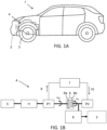
- figure 1A shows schematically a car 1 having a powertrain 4 including a propulsion power source 2, such as internal combustion engine and an electric machine, drivingly connected to driving wheels 3 of the car 1 via a transmission.
- a propulsion power source 2 such as internal combustion engine and an electric machine
- the example powertrain 4 of the hybrid electric vehicle 1 is described more in detail with reference to figure 1B .
- the powertrain 4 of the hybrid electric vehicle comprises an internal combustion engine (ICE) 5 drivingly connected to a first electric machine P1 that is arranged for charging a high-voltage battery 7, as indicated in figure 1B by a charging arrow 9.
- the powertrain 4 further comprises a second electric machine P2 that is powered by the battery 7 and drivingly connected to the vehicle wheels 3 via a transmission 8 for converting the rotational speed of the second electrical motor P2 to suitable vehicle wheel speed. Powering of the second electric machine P2 by means of electrical power from the battery 7 is indicated in figure 1B by a discharging arrow 10.
- the ICE 5 may become drivingly connected to wheels 3 via a dog clutch 6, hence shifting the vehicle from series to parallel hybrid mode.
- the internal combustion engine 5 may be connected to the first electric machine P1 via a dual mass flywheel (DMF) 11.
- the first electric machine P1 is connected to the first part 6a of the dog clutch 6, and the secondary part 6b of the dog clutch 6 is connected to the second electric machine P2.
- Power is supplied to the second electric machine P2 by the battery 7.
- Power levels of the second electric machine P2 may for example be in the range of 50 - 300 kW, specifically in the range of 100-150 kW, depending on the vehicle size.
- the ICE may have a similar power range.
- the designed state feedback Linear Quadratic Integral (LQI) control provides the synchronization torque request to the first electric machine P1, hence matching the speed of the first part 6a of dog clutch 6 with the second part 6b of the dog clutch 6 under the disturbance from combustion torque of the combustion engine 5.
- LQI Linear Quadratic Integral
- the vehicle 1 can be operating in different driving modes.
- the powertrain of the hybrid electric vehicle according to the example illustrated in figure 1B the powertrain can be operated in following driving modes:
- the ICE 5 In pure electric driving mode the ICE 5 is shut off, the dog clutch 6 is set in open state, and the second electric machine P2 is providing the driving torque to the wheels 3.
- the discharge power flow from the battery 7 to the second electric machine P2 is shown by arrow 10.
- the powertrain 5 of the vehicle 1 When state of charge of the battery 7 is low the powertrain 5 of the vehicle 1 may be shifted to series hybrid driving mode. Then the first electric machine P1 motor can take power from the battery 7 for temporarily operating as an engine starter motor. Once the ICE 5 is running, the ICE 5 may for example be used as a range extender and the battery 7 is charged by electrical energy supplied and generated by the first electric machine P1.
- the powertrain 4 of the vehicle 1 may be set in a parallel hybrid driving mode.
- parallel driving mode the dog clutch 6 is closed, hence drivingly connecting the ICE 5 with the vehicle wheels 3.
- Switching the driving mode from pure electric or series hybrid driving mode to parallel driving mode comprises three distinct phases.
- a torque request on the first electric machine P1 is calculated by the feedback controller designed in the later sections of this disclosure.
- primary side 6a of dog clutch 6 consists of two inertias i.e. ICE and the first electric machine P1 connected by an elastic coupling in the dual mass flywheel 11.
- This disclosure provides an algebraic approach for calculating the weighting matrices of the LQI controller based the algebraic Riccati equation, while clearly defining the weighting matrices based on physical parameters of the two inertia system, the required speed synchronization time and limits on speed difference at the end of speed synchronization. This new approach minimizes the need for manual tuning of the controller, while fulfilling the stability and noise rejection requirements.
- Figure 2 shows the first two phases of the mode switch during vehicle acceleration.
- vehicle speed is less than a particular value v init
- the first electric machine P1 is running in generator mode and is applying a constant braking torque on the engine.
- vehicle speed is equal to v init and the speed synchronization phase starts.
- the braking torque of the first electric machine P1 is temporarily increased until the desired engine speed is reached at time point t2, which enables a smooth and noise-free engagement of the primary and secondary sides of the dog clutch 6.
- This braking torque during speed synchronization is calculated by the feedback controller explained in the later sections of this disclosure.
- Speed synchronization between primary and secondary side can alternatively be achieved by simply cutting the fuel to the ICE 5 and letting the speed of the primary side 6a of the dog clutch 6 decrease under friction, but is more controllable to use braking torque from the first electric machine P1.
- the torque at the wheels 3 will be the sum of the torque from ICE 5, and first and second electric machines P1, P2.
- the first phase in the driving mode switch i.e. speed synchronization is not time critical.
- speed synchronization time t synch will change, hence changing the speed v init when the speed synchronization should start.
- the controller design in this disclosure will be focused on speed synchronization and dog clutch engagement without noise and wear.
- Figure 3A shows a schematic illustration of an example embodiment of an actuation mechanism 12 of the dog clutch 6.
- the primary side 6a of the dog clutch comprises a sleeve 13 and hub 14, and they are shown in an enlarged view in figure 3B .
- the hub 14 has outer axially extending dog teeth 16 that are connected to inner axially extending dog teeth 17 of the sleeve 13 for enabling axial motion of the sleeve 13 relative to the hub 14, which is rotationally fastened to the input shaft of the first electric machine P1 via a splines connection 15.
- the disengaged side of the dog clutch 6 is shown in an enlarged view in figure 3C , and the secondary side 6b of the dog clutch 6 comprises outer dog teeth 18 configured for engaging the inner dog teeth 17 of the sleeve 13, when the sleeve 13 is axially displaced towards the secondary side of the dog clutch 6, during engagement of the dog clutch 6.
- the second electric machine P2 is connected to the secondary side of the dog clutch 6 via the transmission 8, as shown in figure 3A and 3C .
- axial displacement of the sleeve 13 towards and away from secondary side of the dog clutch 6, for setting the dog clutch 6 in engaged or disengaged state is for example performed by means of an electric shifter motor that drives a linearly moveable shifter rail 21.
- the rotational to linear motion conversion between shifter motor to shifter rail may for example be accomplished by a shift finger 22.
- axial displacement of the sleeve 13 may be accomplished by means of a shift fork 23 that is fastened to the shifter rail 21 and engages the sleeve 13.
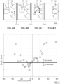
- Figure 4A-4D show the forces and velocities involved on primary and secondary dog teeth, during the engagement process, wherein figure 4A shows a disengaged dog clutch, figure 4B shows the dog clutch while moving towards engagement, figure 4C shows the dog clutch upon dog teeth impact, and figure 4D shows the dog clutch in engaged state.
- Figure 4A shows the relative position of the dog teeth of a disengaged dog clutch at the end of speed synchronization phase.
- Primary dog teeth i.e. dog teeth 17 of sleeve 13
- secondary side dog teeth i.e. dog teeth 18 of secondary side 6b
- ⁇ diff Since the primary side speed ⁇ p is being controlled by the feedback controller and ⁇ s is proportional to the vehicle speed, it can be assumed that, for the short time instance of the engaging phase, ⁇ diff will be constant.
- ⁇ diff ( t synch ) must be very close to zero before the dog clutch engagement.
- Lab tests were done by engaging the dog clutch at different values of ⁇ diff ( t synch ) and measuring the maximum instantaneous angular acceleration and the noise from the dog clutch. The results are shown in figure 5 .
- the pattern of points in figure 5 should be centred around zero ⁇ diff , as ⁇ imp is a function of absolute value of ⁇ diff .
- Figure 6A and 6B shows the axial movement of the primary dog without and with drag torque, respectively.
- ⁇ diff ( t synch ) will be equal to ⁇ diff ( t imp ) , so the impact force would be the same irrespective of the direction of ⁇ diff .
- Figure 6B shows the impact of drag torque, wherein drag torque on either primary or secondary side can be represented by the directional drag torque.
- toque control of the first electric machine P1 is used.
- this is not a trivial control task.
- a controller is designed in the following section.
- the components on the primary side of the dog clutch can be represented by a 2 Degree-Of-Freedom (DOF) torsional system as schematically shown in figure 7 .
- DOE Degree-Of-Freedom
- the torque from the ICE 5 acts on one side of the dual mass flywheel 11, and the torque of the first electric machine P1 on the other side of the dual mass flywheel 11.
- constants a 1 to a 4 in equation 13 and constant b in equation 14 are positive numbers and depend on the physical constants of the system.
- a linear state feedback controller is chosen because it can be easily implemented in the existing transmission control software.
- the plant model is shown on the right side with state feedback controller on the left side indicated by a dashed line, where K is the linear state feedback gain.
- the state feedback can be selected in many ways, but generally it is desirable to find a controller gain that is optimal regarding some criteria.
- One way to find an optimal feedback control law for equation 21 can be obtained by solving infinite time linear quadratic problem, which results in a LQI control.
- J ⁇ 0 ⁇ x T ⁇ Q x T ⁇ + u T ru
- the elements of matrix Q and r define the weights on states and control input in the criteria to be minimized (22).
- the absolute values of Q and r are not important. Rather, it is their relative values which determines the feedback gain of the controller.
- a relative high value on q 4 for instance means that keeping the integral error ⁇ small, is more important than keeping the other states or the control effort small.
- a very high value on r means that it is more important to keep the control effort u small, than to keep the state errors small.
- Equation 22 The values of Q and r in equation 22 may for example be found experimentally, or being calculated based on characteristic equations of the closed loop system. But the characteristic equation has up to now always been based on the controllable canonical form of the system instead of the augmented system shown in equation 19.
- Roots of equation 28 define the poles of the closed loop system and hence define time response of the system.
- the system in equation 19 is a fourth order system, so four poles need to be decided. Once the poles of the system are decided, the solution P to algebraic Riccati equation can be calculated and then feedback gains in equation 24 will be calculated.
- Figure 11 shows the response of a fourth order system with fixed natural frequency w n and variable damping ratios ⁇ .
- Equation 32 can be solved by using figure 12 , which shows the step response of a critically damped fourth order system.
- step input is ⁇ p ref from figure 9
- the output will be ⁇ p .
- the error ⁇ in equation 18 can be used with equation 5 to define error ⁇ ( t synch ). If ⁇ ( t synch ) is within the limits defined in equation 5, the dog clutch can be engaged without noise after time t synch .
- Equation 32 represents the evolution of output or ⁇ p with time.
- the requirement on ⁇ p is such that after time t synch it should reach ⁇ s ( t synch ) within error bounds defined by equation 5.
- Equation 34 represents the location of four poles of the transfer function in equation 29, wherein all four poles are located in the same location.
- constants a 1 to a 4 in equation 13 and constant b in equation 14 are positive numbers and depend on the physical constants of the system.
- p 11 is directly calculable based on the first line of equation 35
- p 14 is directly calculable based on the last line of equation 35.
- p 13 is directly calculable based on the third line of equation 35
- p 12 is directly calculable based on the second line of equation 35.
- q 1 is directly calculable based on the first line of equation set 36
- q 4 is directly calculable based on the last line of equation 36
- p 34 is directly calculable based on the seventh line of equation set 36, based on the previous calculation of p 11 , p 12 , p 13 , p 14 .
- terms p 22 , p 23 , p 24 , p 33 , p 34 , q 2 and q 3 may be solved using conventional matrix calculating, such as for example by eliminating of variables by substituting certain variables, so that a only single equation with a single unknown variable remain, thereby enabling calculation of said unknown variable. Thereafter, the value of this calculated variable may inserted into other equations for calculating the remaining variables.
- control design process feedback gains K and K depend on determining the P matrix based on an arbitrarily chosen positive r as shown in equation 24.
- P is a symmetric matrix as shown in equation 26, it has 10 unknowns instead of 16 unknowns for a non-symmetric matrix.
- the first row/column of P can be calculated by comparing the characteristic polynomial of the closed loop system in 28 with denominator of a fourth order transfer function in 35.
- the denominator can be solved by solving equation 32 for a chosen point in figure 12 .
- controller design process described in this disclosure will also work if matrix Q is not in diagonal form as shown in equation 22. If for instance Q matrix is in a form similar to the one of equation set 36 will be updated accordingly and the system will still have a unique solution if the number of elements in matrix Q are four.
- the resulting controller will be stable since it's a LQI feedback controller having a damping ratio ç set to a positive value, and the integral action guarantees low steady state error. Since the poles are chosen for a critically damped system, the response will reach desired value in short time without overshoot, thereby avoiding need to generate torque from the first electric machine P1 with changing polarity.
- Equation 37 shows the relative value between the said arbitrary selected positive weight r on input u and the weight q 4 on the integral error as defined by equation 22 and 23. It can be seen from equation 37 that the relative value depends on a 4 and b , which are physical parameters of the system as defined by equations 13 and 14 and w n which depends on the desired performance of the system and is derived by functional requirements as shown in equation 33.
- the LQI control implementation approach described in this disclosure gives controller formulation in terms of physical parameters and functional requirements, hence eliminating the need for large number of controller simulation to tune the controller for desired responses. This will save a lot of transmission calibration work, and also eliminate the risk for errors in the calibration process.
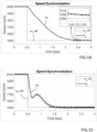
- Figure 13 shows the angular velocities ⁇ p and ⁇ e during speed synchronization.
- Figure 14 shows the control of primary side speed ⁇ p with the target speed ⁇ ref .
- the zoomed in view shown by the dotted box shows that ⁇ after time t synch is less than 5 rpm so according to equation 5 the following dog clutch engagement will be without clonk noise.
- the t synch can be increased according to equation 1 to a level where the noise requirement is fulfilled e.g. t synch being equal to 2sec.
- a non-diagonal form of Q in equation 23 can be calculated by a iterative method using desired close loop poles.
- the desired closed loop poles can be obtained from the method explained above.
- the method further comprises a second step S200 of inserting the obtained values of the physical parameters into predetermined equations for calculating numerical values of the individual terms of a P matrix, wherein the P matrix is the solution to the Algebraic Riccati equation, and wherein said equations include the physical parameters of the system.
- the LQI controller may be calibrated by simply applying the new feedback gains.
- the physical parameters may be any type of parameters associated with a physical system, such as for example inertia, damping constant, spring constant, weight, friction, conductivity, viscosity, etc., depending on the type of system and controllable device.
- the method may also include the step of calculating numerical values of the individual terms of a B matrix, because also the values of the terms of the B matrix is required for calculating the feedback gains.
- each of the equations for calculating the terms of the P matrix is a function of not more than constants, obtainable physical parameters of the dynamic system, other terms of the P matrix, and terms of the Q matrix.
- the physical parameters of the dynamic system are obtained by manually by a user that is measuring, detecting or estimating the values of the physical parameters of the dynamic system; and/or by the electronic control unit that automatically conducts measurements, detects or estimates the values of the physical parameters of the dynamic system.
- the step of calculating feedback gains K for the LQI controller is free from matrix calculation involving a numerical representation of matrix A of the dynamic physical system.
- the method further includes a setup phase of the LQI controller.
- the setup phase is generally performed in connection with designing of the LQI controller for the physical system, and this before said calibration of the feedback gains K.
- the setup phase may include a first step S10 of determining the terms of the matrices A, B and C in form of ones, zeros, and equations having physical constants of the system as expression, while omitting the step of transforming the matrices A, B and C to a controllable canonical form.
- J ⁇ 0 ⁇ x T ⁇ Q x T ⁇ + u T ru
- Q is matrix and r is a scalar
- the LQI feedback controller includes said feedback gains.
- Setting a matrix in a controllable canonical form means transforming for example the A matrix, such that the A matrix has each of the denominator coefficients of the transfer function of the closed loop system, i.e. the coefficients of the characteristic polynomial, showing up negated and in reverse order in the bottom row of the A matrix.
- the equations for the terms of the P matrix are also derived based on the denominator of the transfer function in combination with the coefficients and constant terms of the characteristic polynomial of the closed loop system.
- the method further comprises determining the location of the poles of the transfer function by Laplace-inverse-transforming the denominator of the transfer function and inputting the values of any point of a step response of the transfer function G(s), thereby enabling calculation of the natural frequency w n , which gives the location of the poles of the transfer function.
- the transfer function includes a damping ratio ⁇ , and wherein the damping ratio ⁇ is selected to be equal to about 1.0, or exactly 1.0.
- the step of omitting transformation of one or more of the matrices A, B and C to a controllable canonical form enables the terms of matrices A, B and C to retain their original expressions as functions of detectable system parameters, such that the equations for calculating the terms of the P matrix may be expressed in terms of as functions of detectable system parameters, thereby enabling computational-easy calculation of new feedback gains suitable for implementation in a low-computational system, such as in particular a vehicle system.
- the present disclosure also relates to a general dynamic physical system 28, in particular a vehicle power train, comprising a physical electric or electro-mechanical device 26, such as for example an electric motor, an actuator or the like.
- the electronic control unit 25 further comprises a data memory 27 including predetermined equations for calculating numerical values of the individual terms of a P matrix, wherein the P matrix is the solution to the Algebraic Riccati equation, and wherein said equations include the physical parameters of the system.
- the physical electric or electro-mechanical device 26 of the dynamic physical system is an actuator, a motor, a pump, a light or RF source, or an electro-dynamic device.
- the dynamic physical system 28 is a vehicle system, specifically a vehicle power train system, and more specifically a vehicle power train system having a first electric machine P1 operatively connected to a first part 6a of a dog clutch 6, wherein the electronic controller 25 controls the rotational speed of the first part 6a of the dog clutch 6 for speed synchronising with a second part 6b of the dog clutch 6, such that the first and second dog clutch parts 6a, 6b can be shifted from disengaged state to engaged state in a smooth and noise-free manner.
- the vehicle power train system is implemented in a hybrid electric vehicle having a combustion engine 5 drivingly connected to the first electric machine P1, and second electric machine P2 drivingly connected to the second part 6b of the dog clutch 6, and wherein shifting of the first and second dog clutch parts 6a, 6b from disengaged state to mutually engaged state results in switching from serial to parallel operation of the hybrid electric vehicle.
- the disclosure also relates to a hybrid electric vehicle, wherein a shift of the first and second dog clutch parts from disengaged state to mutually engaged state is configured to switch operation of the hybrid electric vehicle from serial to parallel operation.
- processors include, by way of example, a general purpose processor, a special purpose processor, a conventional processor, a digital signal processor (DSP), a plurality of microprocessors, one or more microprocessors in association with a DSP core, a controller, a microcontroller, Application Specific Integrated Circuits (ASICs), Field Programmable Gate Arrays (FPGAs) circuits, any other type of integrated circuit (IC), and/or a state machine.
- DSP digital signal processor
- ASICs Application Specific Integrated Circuits
- FPGAs Field Programmable Gate Arrays
- ROM read only memory
- RAM random access memory
- register cache memory
- semiconductor memory devices magnetic media such as internal hard disks and removable disks, magneto-optical media, and optical media such as CD-ROM disks, and digital versatile disks (DVDs).
- a non-transitory computer-readable storage medium storing one or more programs configured to be executed by one or more processors of the dynamic physical system 28 having the LQI controller, the one or more programs comprising instructions for performing the method according to any one of the above-discussed embodiments.
- a cloud computing system can be configured to perform any of the method aspects presented herein.
- the cloud computing system may comprise distributed cloud computing resources that jointly perform the method aspects presented herein under control of one or more computer program products.
- the processor may be connected to one or more communication interfaces and/or sensor interfaces for receiving and/transmitting data with external entities such as e.g. sensors arranged on the vehicle surface, an off-site server, or a cloud-based server.
- the processor(s) of the dynamic physical system 28 may be or include any number of hardware components for conducting data or signal processing or for executing computer code stored in memory.
- the system may have an associated memory, and the memory may be one or more devices for storing data and/or computer code for completing or facilitating the various methods described in the present description.
- the memory may include volatile memory or non-volatile memory.
- the memory may include database components, object code components, script components, or any other type of information structure for supporting the various activities of the present description. According to an exemplary embodiment, any distributed or local memory device may be utilized with the systems and methods of this description.
- the memory is communicably connected to the processor (e.g., via a circuit or any other wired, wireless, or network connection) and includes computer code for executing one or more processes described herein.
Landscapes
- Engineering & Computer Science (AREA)
- Transportation (AREA)
- Mechanical Engineering (AREA)
- Chemical & Material Sciences (AREA)
- Combustion & Propulsion (AREA)
- Automation & Control Theory (AREA)
- Human Computer Interaction (AREA)
- Artificial Intelligence (AREA)
- Health & Medical Sciences (AREA)
- Computer Vision & Pattern Recognition (AREA)
- Evolutionary Computation (AREA)
- Medical Informatics (AREA)
- Software Systems (AREA)
- Physics & Mathematics (AREA)
- General Physics & Mathematics (AREA)
- Electric Propulsion And Braking For Vehicles (AREA)
- Feedback Control In General (AREA)
- Vehicle Body Suspensions (AREA)
Abstract

Description
- The present disclosure relates to method for calibrating the feedback gains of an LQI controller. The disclosure further relates to a dynamic physical system comprising an LQI controller.
- The method and system according to the disclosure can be arranged in many types of implementations over a broad technical field, where a low steady state error is required.
- Moreover, even if the method and system according to the disclosure will be described primarily in relation to a hybrid electric powertrain of a car, the method and system are not restricted to this particular implementation, but may alternatively be used or installed or implemented in many other types of implementations having a controllable device, such as an electric machine, an actuator, a power generator, or the like.
- In the area of feedback controllers for controlling nearly any type of dynamic physical systems having a controllable device, the LQI controller operating based on a State Space model representing a physical system is a well-known design.
- Calibration of an LQI controller is generally required upon initial start-up of the physical system, and sometimes also in connection with replacement or maintenance of system hardware, such as replacement/maintenance of actuators, motors, clutches, etc., because such replacement/maintenance may result in different values of relevant system parameters, such as inertia, damping constants, spring constants, friction, actuator speed and acceleration, etc.
- However, calibration of an LQI controller is generally problematic for various reasons. For example, calibration by means of manual tuning of the LQI controller based on try and error approach may be complicated and time-consuming and may result in reduced performance. Furthermore, computer aided calibration involving extensive matrix calculations may be undesirable in technical implementations having relatively low amount of memory and processing power.
- It is thus desirable to provide improved calibration of an LQI controller.
- An object of the present disclosure is to provide a method and system where the previously mentioned problems are avoided. This object is at least partly achieved by the features of the independent claims. The dependent claims contain further developments of the method and system.
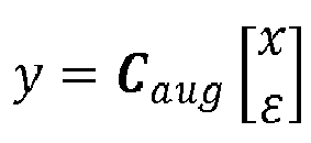
- According to a first aspect of the present disclosure, there is provided a method for calibrating the feedback gains of an LQI controller implemented in an electronic control unit operatively connected for controlling operation of a physical electric or electro-mechanical device of a dynamic physical system, in particular a vehicle power train, wherein the LQI controller is based on an augmented State Space model having the following form:



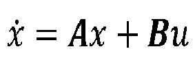
- According to a second aspect of the present disclosure, there is provided a dynamic physical system, in particular a vehicle power train, comprising: a physical electric or electro-mechanical device; and an electronic control unit operatively connected to the physical electric or electro-mechanical device, wherein the electronic control unit comprises an LQI controller configured for controlling operation of the physical electric or electro-mechanical device, wherein the LQI controller is based on an augmented State Space model representing the dynamic physical system, wherein the augmented State Space model may have the following form:




- In this way, it becomes possible to perform calibration of the LQI controller with significantly less processing power, because the matrix calculations may largely be omitted, and the obtained values of the parameters may instead be inserted directly into the equations for calculating the terms for the P matrix. This enables quick and simplified calculation of the P matrix, and subsequently calculation of the new feedback gains, without having to first calculate a numerical version of for example the A matrix, and transformation of this matrix to controllable canonical form. Hence, the method for calibration of an LQI controller according to the present disclosure is particularly beneficial in technical implementations having relatively low amount of memory and processing power, such as for example vehicle implementations.
- Further advantages are achieved by implementing one or several of the features of the dependent claims.
- In some example embodiments, the P matrix is a diagonal matrix having the following form:

- In some example embodiments, that may be combined with any one or more of the above-described embodiments, each of the equations for calculating the terms of the P matrix is a function of not more than constants, obtainable physical parameters of the dynamic system, other terms of the P matrix, and terms of the Q matrix. In other words, the derived equations of the P matrix can be calculated based merely on physical parameters of the physical system.
- In some example embodiments, that may be combined with any one or more of the above-described embodiments, the physical parameters of the dynamic system are obtained by manually by a user that is measuring, detecting or estimating the values of the physical parameters of the dynamic system, and/or by the electronic control unit that automatically conducts measurements, detects or estimates the values of the physical parameters of the dynamic system. The calibration process may thus requires some manual input, unless the system autonomously determines the required updated values of the relevant physical parameters.
- In some example embodiments, that may be combined with any one or more of the above-described embodiments, the step of calculating feedback gains for the LQI controller is free from matrix calculation involving a numerical representation of matrix A of the dynamic physical system. This results in reduced computation load on the CPU for performing the calibration.
- In some example embodiments, that may be combined with any one or more of the above-described embodiments, the method further comprises a setup phase of the LQI controller that is performed before said calibration of the feedback gains K, wherein the setup phase includes: determining the terms of the matrices A, B and C in form of ones, zeros, and equations having physical constants of the system as expression, while omitting the step of transforming the matrices A, B and C to a controllable canonical form; determining a feedback control system having an Integral Linear Quadratic (LQI) controller that outputs system input u that minimizes the criteria J where


- In some example embodiments, that may be combined with any one or more of the above-described embodiments, the characteristic equation of the closed loop control system has the following form:

- In some example embodiments, that may be combined with any one or more of the above-described embodiments, the equations for the terms of the P matrix are also derived based on the denominator of the transfer function in combination with the coefficients and constant terms of the characteristic polynomial of the closed loop system. The transfer function may thus be used for finding the algebraic solution to the equations of the P matrix.
- In some example embodiments, that may be combined with any one or more of the above-described embodiments, the method further comprises determining the location of the poles of the transfer function by Laplace-inverse-transforming the denominator of the transfer function and inputting the values of any point of a step response of the transfer function G(s), thereby enabling calculation of the natural frequency wn , which gives the location of the poles of the transfer function. The location of the poles is generally required for being able to calculate the equations of the terms of the P matrix.
- In some example embodiments, that may be combined with any one or more of the above-described embodiments, the transfer function includes a damping ratio ζ, and wherein the damping ratio ζ is selected to be equal to about 1.0, or exactly 1.0. A critically damped system if often a good choice, because this may eliminate overshoot and thus a simplified control of controllable device.
- In some example embodiments, that may be combined with any one or more of the above-described embodiments, the transfer function includes a natural frequency wn .
- In some example embodiments, that may be combined with any one or more of the above-described embodiments, the Q matrix is a diagonal weight matrix having the following form:

- In some example embodiments, that may be combined with any one or more of the above-described embodiments, the step of omitting transformation of the matrices A, B and C to a controllable canonical form enables the terms of matrices A, B and C to retain their original expressions as functions of detectable system parameters, such that the equations for calculating the terms of the P matrix may be expressed in terms of as functions of detectable system parameters, thereby enabling computational-easy calculation of new feedback gains suitable for implementation in a low-computational system, such as in particular a vehicle system.
- In some example embodiments, that may be combined with any one or more of the above-described embodiments, the physical electric or electro-mechanical device of the dynamic physical system is an actuator, a motor, a pump, a light or RF source, or an electro-dynamic device.
- In some example embodiments, that may be combined with any one or more of the above-described embodiments, the dynamic physical system is a vehicle system, specifically a vehicle power train system, and more specifically a vehicle power train system having a first electric machine operatively connected to a first part of a dog clutch, wherein the electronic controller controls the rotational speed of the first part of the dog clutch for speed synchronising with a second part of the dog clutch, such that the first and second dog clutch parts can be shifted from disengaged state to engaged state in a smooth and noise-free manner. Implementing an LQI controller for the dog clutch that shifts driving mode between serial and parallel hybrid driving mode is beneficial, because a low steady state error is required for ensuring a smooth and noise less engagement, and because the engagement process is not time critical.
- In some example embodiments, that may be combined with any one or more of the above-described embodiments, the vehicle power train system is implemented in a hybrid electric vehicle having a combustion engine drivingly connected to the first electric machine, and second electric machine drivingly connected to the second part of the dog clutch, and wherein shifting of the first and second dog clutch parts from disengaged state to mutually engaged state results in switching from serial to parallel operation of the hybrid electric vehicle. Implementing an LQI controller for the dog clutch that shifts driving mode between serial and parallel hybrid driving mode is beneficial, because a low steady state error is required for ensuring a smooth and noise less engagement, and because the engagement process is not time critical.
- In some example embodiments, that may be combined with any one or more of the above-described embodiments, the physical parameters of the dynamic system are configured to be obtained by manually by a user that is measuring, detecting or estimating the values of the physical parameters of the dynamic system, and/or by the electronic control unit that automatically conducts measurements, detects or estimates the values of the physical parameters of the dynamic system.
- In some example embodiments, that may be combined with any one or more of the above-described embodiments, wherein the data memory further includes the terms of the matrices A, B and C in form of ones, zeros, and equations having physical constants of the system as expression, wherein the matrices A, B and C have not been transformed into a controllable canonical form, wherein the LQI controller is configured to output a control system input u that minimizes the criteria J where J =

- In some example embodiments, that may be combined with any one or more of the above-described embodiments, the matrices A, B and C stored in the data memory have not been transformed into a controllable canonical form, and the terms of matrices A, B and C are therefore retained in their original expressions as functions of detectable system parameters, such that the equations for calculating the terms of the P matrix may be expressed in terms of as functions of detectable system parameters, thereby enabling computational-easy calculation of new feedback gains suitable for implementation in a low-computational system, such as in particular a vehicle system.
- The present disclosure also relates to a hybrid electric vehicle having a vehicle power train system including: a dog clutch having first and second parts; a combustion engine drivingly connected to the first electric machine that is operatively connected to the first part of the dog clutch; a second electric machine drivingly connected to the second part of the dog clutch, and a dynamic physical system as described above.
- In some example embodiments, that may be combined with any one or more of the above-described embodiments, a shift of the first and second dog clutch parts from disengaged state to mutually engaged state is configured to switch operation of the hybrid electric vehicle from serial to parallel operation.
- Further features and advantages of the invention will become apparent when studying the appended claims and the following description. The skilled person in the art realizes that different features of the present disclosure may be combined to create embodiments other than those explicitly described hereinabove and below, without departing from the scope of the present disclosure.
- The method and system according to the disclosure will be described in detail in the following, with reference to the attached drawings, in which
- Fig. 1A
- shows schematically a side-view of a vehicle having a hybrid electric drivetrain,
- Fig. 1B
- shows schematically a layout of an example embodiment of a hybrid electric drivetrain,
- Fig. 2
- shows speed and torque plot over time for a speed synchronization phase,
- Fig. 3
- shows a schematic view of an example embodiment of a dog clutch including a dog clutch actuation mechanism,
- Fig. 4A-D
- show four different phases of a dog teeth engagement,
- Fig. 5
- shows noise result of a lab test of clutch engagements,
- Fig. 6A-B
- show the impact of drag torque on dog teeth motion path during engagement,
- Fig. 7
- shows schematically a 2DOF torsional system,
- Fig. 8
- shows a linear state feedback control system,
- Fig. 9
- shows a speed plot over time for a speed synchronization phase,
- Fig. 10
- shows a linear state feedback control system with LQI controller,
- Fig. 11
- shows a step response of a fourth order system,
- Fig. 12
- shows a step response of a critically damped fourth order system,
- Fig. 13
- shows rotational speed states during speed synchronization,
- Fig. 14
- shows controller performance fulfilling functional requirements,
- Fig. 15
- shows controller performance for different functional requirements,
- Fig. 16
- shows Vibration isolation for controllers with different functional requirements with thick dotted lines for tsynch=2 sec and thin dashed lines for tsynch=1 sec,
- Fig. 17A-B
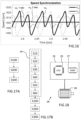
- shows schematically the main steps of two embodiments of the method according to the disclosure,
- Fig. 18
- shows schematically a general system according to the disclosure.
- Various aspects of the disclosure will hereinafter be described in conjunction with the appended drawings to illustrate and not to limit the disclosure, wherein like designations denote like elements, and variations of the described aspects are not restricted to the specifically shown embodiments, but are applicable on other variations of the disclosure.
- The disclosure relates to a method for calibration of an LQI controller that is provided for implementing a feedback control strategy to minimize one or more operational parameters of a physical system, as well as a corresponding dynamic physical system including a LQI controller.
- LQI controllers in general have the advantage of providing a robust state feedback design in combination with no steady state error due to the integrator part, thereby rendering LQI controllers highly useful, for example in in applications where a steady state error is not acceptable.
- The LQI calibration process disclosed herein may thus be implemented in many different types of physical systems in a many different technical areas, such as for example, but not restricted to, vehicles, avionics, marine vessels, energy power generators, etc.
- One specific implementation of a LQI controller is for controlling speed synchronization of a dog clutch prior to engagement for providing a smooth and noise-free cutch engagement process.
- Calibration of the LQI controller enables minimization of mechanical noise during dog clutch engagement. Dog clutches are used in a large variety of technical implementations for enabling selective torque transfer between first and second dog clutch portions.
- Dog clutch engagement process may for example occur during automatic gearshifts in a stepped transmission, such as for example an automatic single or dual clutch transmission, or an automated manual transmissions (AMT), or the like. Alternatively, or in addition, dog clutch engagement process may occur when shifting a conventional dog clutch from disengaged state to engaged state. A conventional dig clutch herein refers to a dog clutch having a first clutch portion rotationally fixed to a first shaft, a second clutch portion rotationally fixed to a second shaft that is separate but aligned with the first shaft. Dog clutch engagement may be accomplished by axially sliding an outer clutch engagement sleeve for selectively setting the first and second clutch portions in rotational connected state. Alternatively, dog clutch engagement may be accomplished by axially sliding for example the first clutch portion relative to the first shaft for selectively setting the first and second clutch portions in rotational connected state.
- The use of a relatively simple and robust dog clutch for selective torque transfer between a power source and a power consumer provides a low cost overall design, and a calibration process of the LQI controller that controls the clutch engagement process may provide substantially interference-free low-noise engagement with little wear, thereby providing increased lifetime, reduced maintenance and improved user satisfaction.
- The method for calibration of an LQI controller, as well as a corresponding dynamic physical system including a LQI controller, will be described more in detail below in an example implementation of the dog clutch in a powertrain of a hybrid electric vehicle. The method and system according to the present disclosure is however not limited to this specific example implementation, but may alternatively be implemented in a large variety of technical systems.
- For setting the dog clutch and vehicle powertrain according to this example embodiment in a context,
figure 1A shows schematically acar 1 having apowertrain 4 including apropulsion power source 2, such as internal combustion engine and an electric machine, drivingly connected to drivingwheels 3 of thecar 1 via a transmission. - The
example powertrain 4 of the hybridelectric vehicle 1 is described more in detail with reference tofigure 1B . Thepowertrain 4 of the hybrid electric vehicle comprises an internal combustion engine (ICE) 5 drivingly connected to a first electric machine P1 that is arranged for charging a high-voltage battery 7, as indicated infigure 1B by a chargingarrow 9. Thepowertrain 4 further comprises a second electric machine P2 that is powered by thebattery 7 and drivingly connected to thevehicle wheels 3 via atransmission 8 for converting the rotational speed of the second electrical motor P2 to suitable vehicle wheel speed. Powering of the second electric machine P2 by means of electrical power from thebattery 7 is indicated infigure 1B by a dischargingarrow 10. - For efficiency during driving, at high vehicle speeds the
ICE 5 may become drivingly connected towheels 3 via adog clutch 6, hence shifting the vehicle from series to parallel hybrid mode. - As schematically illustrated in
figure 1B , theinternal combustion engine 5 may be connected to the first electric machine P1 via a dual mass flywheel (DMF) 11. The first electric machine P1 is connected to thefirst part 6a of thedog clutch 6, and thesecondary part 6b of thedog clutch 6 is connected to the second electric machine P2. Power is supplied to the second electric machine P2 by thebattery 7. Power levels of the second electric machine P2 may for example be in the range of 50 - 300 kW, specifically in the range of 100-150 kW, depending on the vehicle size. The ICE may have a similar power range. - It is shown by experimental results that if the speed difference between the two sides, i.e. first and
second parts dog clutch 6 is below a certain level the engagement will be without clonk noise. In this example embodiment of the disclosure, the designed state feedback Linear Quadratic Integral (LQI) control provides the synchronization torque request to the first electric machine P1, hence matching the speed of thefirst part 6a ofdog clutch 6 with thesecond part 6b of thedog clutch 6 under the disturbance from combustion torque of thecombustion engine 5. - Normally LQI controllers are tuned by trial-and-error methods or by extensive computational-heavy matrix calculations, but this disclosure presents an algebraic approach where the feedback gains of the LQI controller are calculated based solely upon the physical parameters of the system, the required time for speed synchronization and acceptable values of speed difference from experimental results. This approach minimizes the need for manual tuning and can deliver the controller gains for any size and version of the transmission by just modifying the parameter values and functional requirements.
- While driving, the
vehicle 1 can be operating in different driving modes. For example, the powertrain of the hybrid electric vehicle according to the example illustrated infigure 1B , the powertrain can be operated in following driving modes: - 1. Pure Electric
- 2. Series Hybrid
- 3. Parallel Hybrid
- In pure electric driving mode the
ICE 5 is shut off, thedog clutch 6 is set in open state, and the second electric machine P2 is providing the driving torque to thewheels 3. The discharge power flow from thebattery 7 to the second electric machine P2 is shown byarrow 10. - When state of charge of the
battery 7 is low thepowertrain 5 of thevehicle 1 may be shifted to series hybrid driving mode. Then the first electric machine P1 motor can take power from thebattery 7 for temporarily operating as an engine starter motor. Once theICE 5 is running, theICE 5 may for example be used as a range extender and thebattery 7 is charged by electrical energy supplied and generated by the first electric machine P1. - Furthermore, when the vehicle speed is larger than a particular value v 1, for efficiency the
powertrain 4 of thevehicle 1 may be set in a parallel hybrid driving mode. In parallel driving mode thedog clutch 6 is closed, hence drivingly connecting theICE 5 with thevehicle wheels 3. Switching the driving mode from pure electric or series hybrid driving mode to parallel driving mode comprises three distinct phases. - 1. Speed synchronization
- 2. Dog clutch engagement
- 3. Torque Ramp up
- In the first phase "Speed synchronization" the rotational speed ωp of
primary side 6a ofdog clutch 6, infigure 1B is controlled, by means of the first electric machine P1, to match the rotational speed ωs ofsecondary side 6b ofdog clutch 6. The speed difference the primary andsecondary sides dog clutch 6, i.e. speed different between ωp and ωs , at the end ofphase 1 determines the level of noise generated in phase 2: "Dog Clutch Engagement". Experimental results presented in this disclosure show the limits on speed difference at the end ofphase 1 which will lead to noise-less dog clutch engagement. - To minimize the speed difference at dog clutch engagement, a torque request on the first electric machine P1 is calculated by the feedback controller designed in the later sections of this disclosure. From
figure 1B , it can be seen thatprimary side 6a ofdog clutch 6 consists of two inertias i.e. ICE and the first electric machine P1 connected by an elastic coupling in thedual mass flywheel 11. This disclosure provides an algebraic approach for calculating the weighting matrices of the LQI controller based the algebraic Riccati equation, while clearly defining the weighting matrices based on physical parameters of the two inertia system, the required speed synchronization time and limits on speed difference at the end of speed synchronization. This new approach minimizes the need for manual tuning of the controller, while fulfilling the stability and noise rejection requirements. -
Figure 2 shows the first two phases of the mode switch during vehicle acceleration. Before time point t1, vehicle speed is less than a particular value vinit , the first electric machine P1 is running in generator mode and is applying a constant braking torque on the engine. At time point t1, vehicle speed is equal to vinit and the speed synchronization phase starts. During the speed synchronization phase, the braking torque of the first electric machine P1 is temporarily increased until the desired engine speed is reached at time point t2, which enables a smooth and noise-free engagement of the primary and secondary sides of thedog clutch 6. This braking torque during speed synchronization is calculated by the feedback controller explained in the later sections of this disclosure. - Speed synchronization between primary and secondary side can alternatively be achieved by simply cutting the fuel to the
ICE 5 and letting the speed of theprimary side 6a of thedog clutch 6 decrease under friction, but is more controllable to use braking torque from the first electric machine P1. - Speed synchronization takes time tsynch. It is assumed that the speed ωs of the
secondary side 6b thedog clutch 6 at time point t2 is accurately predicted by the hybrid electric powertrain, and vehicle speed is equal to v 1 at time point t2. Based on vehicle acceleration aveh, duration of the synchronisation time tsynch, vehicle speed v 1 at time point t2, and vehicle speed vinit at time point t1 can be calculated by
- In this disclosure

- Since speed synchronization is not time critical for this particular transmission, two seconds is a reasonable choice. Once the speed synchronization phase is finished, the second phase "Dog clutch engagement" is started. If the speed is matched perfectly there will be minimum noise and wear in the transmission.
- The speed difference ωdiff is defined as

- After dog clutch engagement the torque at the
wheels 3 will be the sum of the torque fromICE 5, and first and second electric machines P1, P2. To keep a smooth acceleration of the vehicle during the driving mode shift, it may be desirable to manage the torque from all sources such that the toque demand for constant acceleration is fulfilled during the whole driving mode shift. - From the above section it can be concluded that the first phase in the driving mode switch i.e. speed synchronization is not time critical. Depending on the power available for the first electric machine P1 for speed synchronization, synchronization time tsynch will change, hence changing the speed vinit when the speed synchronization should start. As opposed to transmissions in conventional powertrains, where driving mode switch and speed synchronization is a time critical problem for fulfilling the torque request, the controller design in this disclosure will be focused on speed synchronization and dog clutch engagement without noise and wear.
-
Figure 3A shows a schematic illustration of an example embodiment of anactuation mechanism 12 of thedog clutch 6. In this example embodiment, theprimary side 6a of the dog clutch comprises asleeve 13 andhub 14, and they are shown in an enlarged view infigure 3B . Thehub 14 has outer axially extending dog teeth 16 that are connected to inner axially extendingdog teeth 17 of thesleeve 13 for enabling axial motion of thesleeve 13 relative to thehub 14, which is rotationally fastened to the input shaft of the first electric machine P1 via asplines connection 15. - The disengaged side of the
dog clutch 6 is shown in an enlarged view infigure 3C , and thesecondary side 6b of thedog clutch 6 comprisesouter dog teeth 18 configured for engaging theinner dog teeth 17 of thesleeve 13, when thesleeve 13 is axially displaced towards the secondary side of thedog clutch 6, during engagement of thedog clutch 6. The second electric machine P2 is connected to the secondary side of thedog clutch 6 via thetransmission 8, as shown infigure 3A and 3C . - With reference to
figure 3A , axial displacement of thesleeve 13 towards and away from secondary side of thedog clutch 6, for setting thedog clutch 6 in engaged or disengaged state, is for example performed by means of an electric shifter motor that drives a linearly moveable shifter rail 21. The rotational to linear motion conversion between shifter motor to shifter rail may for example be accomplished by a shift finger 22. Moreover, axial displacement of thesleeve 13 may be accomplished by means of ashift fork 23 that is fastened to the shifter rail 21 and engages thesleeve 13. -
Figure 4A-4D show the forces and velocities involved on primary and secondary dog teeth, during the engagement process, whereinfigure 4A shows a disengaged dog clutch,figure 4B shows the dog clutch while moving towards engagement,figure 4C shows the dog clutch upon dog teeth impact, andfigure 4D shows the dog clutch in engaged state. -
Figure 4A shows the relative position of the dog teeth of a disengaged dog clutch at the end of speed synchronization phase. Primary dog teeth, i.e.dog teeth 17 ofsleeve 13, are moving with a rotational speed ωp and secondary side dog teeth, i.e.dog teeth 18 ofsecondary side 6b, are moving with rotational speed ωs . - When the
shifter motor 20 is rotated in the shift direction shown by rotational arrow inFigure 3A , theshift fork 23 will move thesleeve 13 with an axial velocity ẋp as shown inFigure 4B . The rotational speed difference can be simplified by assuming that thesecondary teeth 18 are at rest and theprimary teeth 17 are rotating with the speed difference ωdiff defined byequation 3. - Since the primary side speed ωp is being controlled by the feedback controller and ωs is proportional to the vehicle speed, it can be assumed that, for the short time instance of the engaging phase, ωdiff will be constant.
- When the
primary dog teeth 17 have moved a certain distance at time timp , they will come into contact with thesecondary dog teeth 18 as shown infigure 4C . Depending on the axial speed ẋp and the rotational speed difference ωdiff at timp , an impact force Fimp, normal to the impact surface, will be generated on both teeth. The impact force will be directly proportional to ωdiff (timp ) and ẋp and is responsible for noise and wear. - The axial component Fxi of the impact force Fimp shown in
figure 4C will resist the engagement and is overcome by the shifter motor 21 shown infigure 3A . Once theprimary dog teeth 17 have moved a certain distance and are engaged with thesecondary dog teeth 18, at time tend , the third phase of the driving mode shift can be started, namely the "Torque Ramp up" phase. - At time timp , when the
dog teeth 
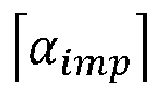
- During normal operation of the vehicle, ωdiff (tsynch ) must be very close to zero before the dog clutch engagement. Lab tests were done by engaging the dog clutch at different values of ωdiff (tsynch ) and measuring the maximum instantaneous angular acceleration and the noise from the dog clutch. The results are shown in
figure 5 . - It can be seen from
figure 5 , that if αimp is higher than a particular value clonk sound is heard during engagement. As shown in equation 4 a higher αimp means a higher impact force Fimp. Higher impact force Fimp is in turn a result of a higher ωdiff. Fromfigure 5 , it can be seen that if ωdiff (tsynch ) is between -20 and 5 rpm there will most probably be no clonk sound. - During the lab tests shown in
figure 5 , the primary side speed ωp is not controlled, so from time instance tsynch to tend the rotational speed difference ωdiff is not constant due to drag torque in the transmission. - Ideally, the pattern of points in
figure 5 , should be centred around zero ωdiff, as αimp is a function of absolute value of ωdiff. -
Figure 6A and 6B shows the axial movement of the primary dog without and with drag torque, respectively. As shown infigure 6A , if there is no drag torque in the transmission, then ωdiff (tsynch ) will be equal to ωdiff (timp ), so the impact force would be the same irrespective of the direction of ωdiff .Figure 6B on the other hand shows the impact of drag torque, wherein drag torque on either primary or secondary side can be represented by the directional drag torque. - The effect of directional drag torque will be different depending on the direction of ωdiff. For the drag torque shown in
figure 6B , it can be seen that ωdiff (timp ) is less than ωdiff (tsynch ), if ωdiff is in downwards direction resulting in lower Fimp and αimp than if ωdiff is in upwards direction. Consequently the noise produced by the impact will be lower if ωdiff is in downwards direction. - For this disclosure based on
figure 5 and figure 6A-B , it can be safely assumed that
- To control the primary speed ωp to right value before the
dog clutch 6 can be engaged, toque control of the first electric machine P1 is used. However, due to thedual mass flywheel 11 and the time variations of the engine torque, this is not a trivial control task. To ensure a fast, accurate and robust control of the primary speed, a controller is designed in the following section. - The components on the primary side of the dog clutch can be represented by a 2 Degree-Of-Freedom (DOF) torsional system as schematically shown in
figure 7 . - The torque from the
ICE 5 acts on one side of thedual mass flywheel 11, and the torque of the first electric machine P1 on the other side of thedual mass flywheel 11. In between are several inertias, which can be lumped together into two inertias connected via a torsional spring and damper. The two inertias are
- The torque TDMF applied by the torsional spring and damper of the DMF on both the inertias Jp and Je is

- Defining Δθ, such that

- Applying Newton's 2nd law on inertia Jp and Je a set of two differential equations describing the speed dynamics of the system are obtained:

- Differentiating
equation 8 on both sides gives
- Combing the differential equations in
equations figure 7 can be obtained by setting the disturbance TICE = 0, such that



- The constants a 1 to a 4 in
equation 13 and constant b inequation 14 are positive numbers and depend on the physical constants of the system. - Vector C in
equation 11 will be
- For synchronizing the speed of the primary side of the dog clutch the input u to the system will be the torque request from the first electric machine P1 so

- A linear state feedback controller is chosen because it can be easily implemented in the existing transmission control software. In
figure 8 the plant model is shown on the right side with state feedback controller on the left side indicated by a dashed line, where K is the linear state feedback gain. - From
figure 8 , the torque request on the first electric machine P1 in equation 16 can be rewritten as
- In order to minimize the speed difference ωdiff in
equation 3 under the disturbance from TICE, the first state of the system inequation 12 ωp, needs to reach the target speed shown by ωp ref as shown infigure 9 . - From
figure 9 , it can be seen that at time tsynch, ωp ref is equal to ωs , so if ωp reaches ωp ref, after time tsynch, dog clutch can be engaged without noise. To analyze the control of the speed an error ε can be introduced
- Adding the integral of the error ε in the system (11) as an additional state, an integral action of the feedback control is obtained which will eliminate the steady state error. With this new state the augmented state space model will be


- The feedback control system in
figure 8 updated with the integral state and reference ωp ref is shown infigure 10. Figure 10 this describes a reference tracking integral control system. - From
figure 10 , the torque request u on the first electric machine P1 can be rewritten as
- The state feedback can be selected in many ways, but generally it is desirable to find a controller gain that is optimal regarding some criteria. One way to find an optimal feedback control law for equation 21 can be obtained by solving infinite time linear quadratic problem, which results in a LQI control. This type of controller outputs the control input u that minimizes the criteria J where

- Matrix Q and scalar r in equation 22 can be defined as

- The elements of matrix Q and r, define the weights on states and control input in the criteria to be minimized (22). When determining the LQI controller gain, the absolute values of Q and r are not important. Rather, it is their relative values which determines the feedback gain of the controller. A relative high value on q 4 for instance means that keeping the integral error ε small, is more important than keeping the other states or the control effort small. A very high value on r means that it is more important to keep the control effort u small, than to keep the state errors small.
- The feedback gains K and KI in equation 21 can, for an LQI controller, be calculated by



- The values of Q and r in equation 22 may for example be found experimentally, or being calculated based on characteristic equations of the closed loop system. But the characteristic equation has up to now always been based on the controllable canonical form of the system instead of the augmented system shown in
equation 19. - It is desirable to be able to calculate the new feedback gains directly based on physical system parameters, because this enables a quick and simply calibration of the LQI controller, without need for extensive processing power. To keep the values of feedback gains in
equation 24 dependent on the physical parameters of the system, the A, B and C matrices are not transformed to the controllable canonical form, because this would require inserting values of the physical parameters of the system at an early stage. - The core idea of the method for controller calibration in the following sections of this disclosure is to
- Minimize the need for manual tuning
- Be based on physical properties of the system and functional requirements so it can be used on any size and version of the transmission without needing to change anything other than parameter values
- Guaranteed stability
- Low steady state error
- Noise rejection
- The characteristic equation of the closed loop system in
figure 10 can be written as
- Substituting K from
equation 24 inequation 27
- Roots of
equation 28 define the poles of the closed loop system and hence define time response of the system. The system inequation 19 is a fourth order system, so four poles need to be decided. Once the poles of the system are decided, the solution P to algebraic Riccati equation can be calculated and then feedback gains inequation 24 will be calculated. - The transfer function of a 4th order system is

-
Figure 11 shows the response of a fourth order system with fixed natural frequency wn and variable damping ratios ζ. - From
figure 11 , it can be seen that the critically damped response reaches the steady state value in the least time. The under damped response is faster to reach the desired speed but does not stay there and continues and produces an overshoot. Since in this disclosure the control problem deals with speed synchronization, an overshoot will create NVH issues so, a critically damped system is chosen. - With ç = 1, and input(s) being a unit step the transfer function in
equation 29 becomes
- Using partial fractions equation 30 becomes

- Taking Laplace inverse on both sides of equation 31

- Equation 32 can be solved by using
figure 12 , which shows the step response of a critically damped fourth order system. - In
figure 12 , if step input is ωp ref fromfigure 9 , the output will be ωp. The error ε inequation 18 can be used withequation 5 to define error ε(tsynch ). If ε(tsynch ) is within the limits defined inequation 5, the dog clutch can be engaged without noise after time tsynch. - Equation 32, represents the evolution of output or ωp with time. The requirement on ωp is such that after time tsynch it should reach ωs (tsynch ) within error bounds defined by
equation 5. So equation 32 can be rewritten as
- Since equation 33 has one unknown wn it can be solved, and the solution will be of the form

- Equation 34 represents the location of four poles of the transfer function in
equation 29, wherein all four poles are located in the same location. - In this step value of wn from equation 34 will be used in denominator polynomial of transfer function in 29 to determine the elements in the P matrix.
- By comparing the coefficients for s 3 , s 2 , s and the constant term in
equation 28 with denominator polynomial ofequation 29, the following equation set is obtained, wherein p 11, p 12, p 13 and p 14 are unknowns that must be calculated:
- The constants a 1 to a 4 in
equation 13 and constant b inequation 14 are positive numbers and depend on the physical constants of the system. - Since equation set 35 has four unknowns p 11, p 12, p 13 and p 14 and four equations, a unique solution of each of said unknowns can be calculated by setting ç = 1 and setting r an arbitrary positive number, such as for example 1.
- Specifically, p11 is directly calculable based on the first line of equation 35, and p14 is directly calculable based on the last line of equation 35. Thereafter, p13 is directly calculable based on the third line of equation 35, and finally p12 is directly calculable based on the second line of equation 35.
- After solving equation set 35, there will be six remaining unknown elements left in the P matrix in
equation 26, also the four elements of the Q matrix inequation 23 need to be calculated. This requires 10 equations that can be obtained from matrix equation 25, wherein the terms p 22, p 23, p 24, p 33, p 34 and p 44 of the P matrix and q 1, q 2, q 3 and q 4 of the Q matrix are the unknowns that must be calculated:
- Thereafter, terms p 22, p 23, p 24, p 33, p 34, q 2 and q 3 may be solved using conventional matrix calculating, such as for example by eliminating of variables by substituting certain variables, so that a only single equation with a single unknown variable remain, thereby enabling calculation of said unknown variable. Thereafter, the value of this calculated variable may inserted into other equations for calculating the remaining variables.
- After solving equation set 36, the six remaining elements of P matrix that were p 22, p 23, p 24, p 33, p 34 and p 44 have been calculated along with the four elements of matrix Q, which are q 1, q2, q 3 and q 4.
- Once solution P to the Riccati equation in
equation 26 is calculated the linear feedback gains K and K, can be calculated byequation 24, wherein the variable r is set to the previously chosen arbitrary positive number, hence concluding the controller design. - To summarize, the control design process feedback gains K and K, depend on determining the P matrix based on an arbitrarily chosen positive r as shown in
equation 24. - Since P is a symmetric matrix as shown in
equation 26, it has 10 unknowns instead of 16 unknowns for a non-symmetric matrix. The first row/column of P can be calculated by comparing the characteristic polynomial of the closed loop system in 28 with denominator of a fourth order transfer function in 35. - The denominator can be solved by solving equation 32 for a chosen point in
figure 12 . - The rest of the elements in P and diagonal matrix Q can then be solved using Riccati equation.
- It is worth noting that the controller design process described in this disclosure will also work if matrix Q is not in diagonal form as shown in equation 22. If for instance Q matrix is in a form similar to the one of equation set 36 will be updated accordingly and the system will still have a unique solution if the number of elements in matrix Q are four.
- The resulting controller will be stable since it's a LQI feedback controller having a damping ratio ç set to a positive value, and the integral action guarantees low steady state error. Since the poles are chosen for a critically damped system, the response will reach desired value in short time without overshoot, thereby avoiding need to generate torque from the first electric machine P1 with changing polarity.
- Substituting value of p 14 in the last equation of equation set 36 from last equation of equation set 35 following equation is obtained:

- Equation 37 shows the relative value between the said arbitrary selected positive weight r on input u and the weight q 4 on the integral error as defined by
equation 22 and 23. It can be seen from equation 37 that the relative value depends on a 4 and b, which are physical parameters of the system as defined byequations - Hence, to fulfil the functional requirements for a particular physical system the relative weighting between q 4 and r must be as defined by equation 37.
- It can also be shown that the other weights q 1, q 2 and q 3 relative to r, will also solely depend on physical parameters in matrices A and B from
equations figure 12 . - So, the LQI control implementation approach described in this disclosure gives controller formulation in terms of physical parameters and functional requirements, hence eliminating the need for large number of controller simulation to tune the controller for desired responses. This will save a lot of transmission calibration work, and also eliminate the risk for errors in the calibration process.
- To demonstrate the performance of a controller designed with the presented method, simulations on a 2DOF torsional system representing ICE, dual mass flywheel and first electric machine P1 was performed.
-
Figure 13 shows the angular velocities ωp and ωe during speed synchronization. - From
figure 12 , when the vehicle speed is lower than vinit theICE 5 and primary side of dog clutch 6a are running at 2000 rpm. At 0.5 seconds infigure 13 , when the vehicle speed becomes larger than vinit the speed synchronization starts and primary side speed drops to 1500 rpm within 2 seconds, which is time tsynch as defined byequation 2. -
Figure 14 shows the control of primary side speed ωp with the target speed ωref . The zoomed in view shown by the dotted box shows that ε after time tsynch is less than 5 rpm so according toequation 5 the following dog clutch engagement will be without clonk noise. - If the functional requirement of tsynch is changed from 2 sec from
equation 2 to 1 sec, and the controller is redesigned, the new controller's performance is shown infigure 15 . - From
figure 15 , it can be seen that the synchronization time requirement of 1 sec is fulfilled but the error after time tsynch is not within the limits defined byequation 5. - The reason can be seen by investigating the resulting magnitude of q 2 in
equation 23, which fromequations 22 and 12 is the weight defined for the state Δθ of the system. A high value of q 2 implies that Δθ should be very small. A very small Δθ according toequation 8 means that the vibration isolation between engine and the primary side of dog clutch will be poor. This can be seen by comparing the magnitudes of fluctuations in ωp for controller designed for tsynch equal to 1 second shown by thin dotted line marked "ω p 1 sec" infigure 16 and ωp for tsynch equal to 2 seconds shown by thick line marked with "ω p 2 sec" infigure 16 . -
Figure 16 shows vibration isolation for controllers with different functional requirements with thick dotted lines for tsynch = 2 sec and thin dashed lines for tsynch = 1 sec. - From
figure 16 , it can be seen that fluctuations in ωe under the influence of the disturbance TICE is same for both controllers. - For the controller designed using the approach described the value of q 2 for tsynch = 1 sec is 170 times more than that for tsynch = 2 sec and hence the poor vibration isolation and unfulfillment of error after time tsynch in
figure 15 as compared tofigure 14 . - For the particular problem of speed synchronization in the hybrid powertrain described in this example embodiment of the disclosure, it is not an issue that the synchronization time is long because the speed synchronization is not time critical. So by decreasing vinit in
figure 2 , the tsynch can be increased according toequation 1 to a level where the noise requirement is fulfilled e.g. tsynch being equal to 2sec. - Alternatively a non-diagonal form of Q in
equation 23 can be calculated by a iterative method using desired close loop poles. The desired closed loop poles can be obtained from the method explained above. - The calibration method and corresponding dynamic physical system of the present disclosure have been described above in detail with reference to
figures 1A-16 and in the context of the specific implementation of controlling clutch engagement process of a dog clutch. However, as mentioned earlier in the text, the calibration method and corresponding dynamic physical system of the present disclosure is not restricted to this example embodiment but may be advantageously used also in other technical implementations having a controller for controlling a controllable device. - Consequently, with reference to
figure 17A , the present disclosure relates to a general method for calibrating the feedback gains K of an LQI controller implemented in an electronic control unit operatively connected for controlling operation of a physical electric or electro-mechanical device of a dynamic physical system, in particular a vehicle power train, wherein the LQI controller is based on an augmented State Space model having the following form: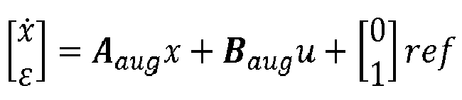


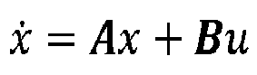


- Thereby, the LQI controller may be calibrated by simply applying the new feedback gains.
- The physical parameters may be any type of parameters associated with a physical system, such as for example inertia, damping constant, spring constant, weight, friction, conductivity, viscosity, etc., depending on the type of system and controllable device.
- Furthermore, the method may also include the step of calculating numerical values of the individual terms of a B matrix, because also the values of the terms of the B matrix is required for calculating the feedback gains.
- In some example embodiments, the P matrix is a diagonal matrix having the following form:

- In some example embodiments, each of the equations for calculating the terms of the P matrix is a function of not more than constants, obtainable physical parameters of the dynamic system, other terms of the P matrix, and terms of the Q matrix.
- In some example embodiments, the physical parameters of the dynamic system are obtained by manually by a user that is measuring, detecting or estimating the values of the physical parameters of the dynamic system; and/or by the electronic control unit that automatically conducts measurements, detects or estimates the values of the physical parameters of the dynamic system.
- In some example embodiments, the step of calculating feedback gains K for the LQI controller is free from matrix calculation involving a numerical representation of matrix A of the dynamic physical system.
- In some example embodiments, the method further includes a setup phase of the LQI controller. The setup phase is generally performed in connection with designing of the LQI controller for the physical system, and this before said calibration of the feedback gains K. With reference to
figure 17B , the setup phase may include a first step S10 of determining the terms of the matrices A, B and C in form of ones, zeros, and equations having physical constants of the system as expression, while omitting the step of transforming the matrices A, B and C to a controllable canonical form. A second step S20 of determining a feedback control system having an Integral Linear Quadratic (LQI) controller that outputs system input u that minimizes the criteria J where J =

- Setting a matrix in a controllable canonical form means transforming for example the A matrix, such that the A matrix has each of the denominator coefficients of the transfer function of the closed loop system, i.e. the coefficients of the characteristic polynomial, showing up negated and in reverse order in the bottom row of the A matrix.
- In some example embodiments, the characteristic equation of the closed loop control system has the following form:

- In some example embodiments, the equations for the terms of the P matrix are also derived based on the denominator of the transfer function in combination with the coefficients and constant terms of the characteristic polynomial of the closed loop system.
- In some example embodiments, the method further comprises determining the location of the poles of the transfer function by Laplace-inverse-transforming the denominator of the transfer function and inputting the values of any point of a step response of the transfer function G(s), thereby enabling calculation of the natural frequency wn , which gives the location of the poles of the transfer function.
- In some example embodiments, the transfer function includes a damping ratio ζ, and wherein the damping ratio ζ is selected to be equal to about 1.0, or exactly 1.0.
- In some example embodiments, the Q matrix is a diagonal weight matrix having the following form:

- In some example embodiments, the step of omitting transformation of one or more of the matrices A, B and C to a controllable canonical form enables the terms of matrices A, B and C to retain their original expressions as functions of detectable system parameters, such that the equations for calculating the terms of the P matrix may be expressed in terms of as functions of detectable system parameters, thereby enabling computational-easy calculation of new feedback gains suitable for implementation in a low-computational system, such as in particular a vehicle system.
- In addition, with reference to
figure 18 , the present disclosure also relates to a general dynamicphysical system 28, in particular a vehicle power train, comprising a physical electric or electro-mechanical device 26, such as for example an electric motor, an actuator or the like. The dynamicphysical system 28 further comprises anelectronic control unit 25 operatively connected to the physical electric or electro-mechanical device 26, wherein theelectronic control unit 25 comprises aCPU 29 suitable for executing a code for implementing a LQI controller configured for controlling operation of the physical electric or electro-mechanical device 26, wherein the LQI controller is based on an augmented State Space model representing the dynamic physical system, wherein the augmented State Space model may have the following form:


electronic control unit 25 further comprises adata memory 27 including predetermined equations for calculating numerical values of the individual terms of a P matrix, wherein the P matrix is the solution to the Algebraic Riccati equation, and wherein said equations include the physical parameters of the system. The feedback gains of the LQI controller is configured to be calibrated by: obtaining values of various physical parameters of the dynamic system; inserting the obtained values of the physical parameters into the predetermined equations for calculating numerical values of the individual terms of a P matrix; and calculating new feedback gains for the LQI controller based on the matrix equation
- In some example embodiments, the physical electric or electro-
mechanical device 26 of the dynamic physical system is an actuator, a motor, a pump, a light or RF source, or an electro-dynamic device. - In some example embodiments, the dynamic
physical system 28 is a vehicle system, specifically a vehicle power train system, and more specifically a vehicle power train system having a first electric machine P1 operatively connected to afirst part 6a of adog clutch 6, wherein theelectronic controller 25 controls the rotational speed of thefirst part 6a of thedog clutch 6 for speed synchronising with asecond part 6b of thedog clutch 6, such that the first and second dogclutch parts - In some example embodiments, the vehicle power train system is implemented in a hybrid electric vehicle having a
combustion engine 5 drivingly connected to the first electric machine P1, and second electric machine P2 drivingly connected to thesecond part 6b of thedog clutch 6, and wherein shifting of the first and second dogclutch parts - The disclosure also relates to a hybrid electric vehicle, wherein a shift of the first and second dog clutch parts from disengaged state to mutually engaged state is configured to switch operation of the hybrid electric vehicle from serial to parallel operation.
- The present disclosure has been presented above with reference to specific embodiments. However, other embodiments than the above described are possible and within the scope of the disclosure. Different method steps than those described above, performing the method by hardware or software, may be provided within the scope of the disclosure.
- The methods disclosed herein may be implemented in a general purpose computer, a processor, or a processor core. Suitable processors include, by way of example, a general purpose processor, a special purpose processor, a conventional processor, a digital signal processor (DSP), a plurality of microprocessors, one or more microprocessors in association with a DSP core, a controller, a microcontroller, Application Specific Integrated Circuits (ASICs), Field Programmable Gate Arrays (FPGAs) circuits, any other type of integrated circuit (IC), and/or a state machine.
- The methods or flow charts provided herein may be implemented in a computer program, software, or firmware incorporated in a computer-readable storage medium for execution by a general purpose computer or a processor. Examples of computer-readable storage mediums include a read only memory (ROM), a random access memory (RAM), a register, cache memory, semiconductor memory devices, magnetic media such as internal hard disks and removable disks, magneto-optical media, and optical media such as CD-ROM disks, and digital versatile disks (DVDs).
- Thus, according to an exemplary embodiment, there is provided a non-transitory computer-readable storage medium storing one or more programs configured to be executed by one or more processors of the dynamic
physical system 28 having the LQI controller, the one or more programs comprising instructions for performing the method according to any one of the above-discussed embodiments. Alternatively, according to another exemplary embodiment a cloud computing system can be configured to perform any of the method aspects presented herein. The cloud computing system may comprise distributed cloud computing resources that jointly perform the method aspects presented herein under control of one or more computer program products. Moreover, the processor may be connected to one or more communication interfaces and/or sensor interfaces for receiving and/transmitting data with external entities such as e.g. sensors arranged on the vehicle surface, an off-site server, or a cloud-based server. - The processor(s) of the dynamic
physical system 28 may be or include any number of hardware components for conducting data or signal processing or for executing computer code stored in memory. The system may have an associated memory, and the memory may be one or more devices for storing data and/or computer code for completing or facilitating the various methods described in the present description. The memory may include volatile memory or non-volatile memory. The memory may include database components, object code components, script components, or any other type of information structure for supporting the various activities of the present description. According to an exemplary embodiment, any distributed or local memory device may be utilized with the systems and methods of this description. According to an exemplary embodiment the memory is communicably connected to the processor (e.g., via a circuit or any other wired, wireless, or network connection) and includes computer code for executing one or more processes described herein. - It will be appreciated that the above description is merely exemplary in nature and is not intended to limit the present disclosure, its application or uses. While specific examples have been described in the specification and illustrated in the drawings, it will be understood by those of ordinary skill in the art that various changes may be made and equivalents may be substituted for elements thereof without departing from the scope of the present disclosure as defined in the claims. Furthermore, modifications may be made to adapt a particular situation or material to the teachings of the present disclosure without departing from the essential scope thereof.
- Therefore, it is intended that the present disclosure not be limited to the particular examples illustrated by the drawings and described in the specification as the best mode presently contemplated for carrying out the teachings of the present disclosure, but that the scope of the present disclosure will include any embodiments falling within the foregoing description and the appended claims. Reference signs mentioned in the claims should not be seen as limiting the extent of the matter protected by the claims, and their sole function is to make claims easier to understand.
-
- 1.
- Car
- 2.
- Propulsion power source
- 3.
- Wheels
- 4.
- Powertrain
- 5.
- Internal combustion engine
- 6.
- Dog clutch
- 7.
- Battery
- 8.
- Transmission
- 9.
- Charging flow
- 10.
- Discharging flow
- 11.
- Dual mass flywheel
- 12.
- Actuation mechanism
- 13.
- Sleeve
- 14.
- Hub
- 15.
- Splines connection
- 16.
- Dog teeth of hub
- 17.
- Dog teeth of sleeve
- 18.
- Dog teeth of secondary side
- 19.
- Transmission gear
- 20.
- Shifter motor
- 21.
- Shifter rail
- 22.
- Shift finger
- 23.
- Shift fork
- 24.
- Setup phase
- 25.
- Electronic control unit
- 26.
- Physical controllable device
- 27.
- Data memory
- 28.
- Physical system
- 29.
- CPU
- P1.
- First electric motor
- P2.
- Second electric motor
Claims (15)
- A method for calibrating the feedback gains K of an LQI controller implemented in an electronic control unit (25) operatively connected for controlling operation of a physical electric or electro-mechanical device (26) of a dynamic physical system (28), in particular a vehicle powertrain (4), wherein the LQI controller is based on an augmented State Space model having the following form:


 wherein the augmented State Space model is based on the following State Space model representing the physical system:
 wherein x is control system state vector, ε is control system tracking error, u is control system input, ref is control system target references value, y is control system output, and A, B, C represent matrices derived from a mathematical model of the dynamic physical system,wherein the method of calibrating the LQI controller comprises:obtaining values of various physical parameters of the dynamic physical system (28);inserting the obtained values of the physical parameters into predetermined equations for calculating numerical values of the individual terms of a P matrix, wherein the P matrix is the solution to the Algebraic Riccati equation, and wherein said equations include the physical parameters of the system (28); andcalculating new feedback gains for the LQI controller based on the matrix equation
- The method according to claim 1, wherein each of the equations for calculating the terms of the P matrix is a function of not more than constants, obtainable physical parameters of the dynamic physical system (28), other terms of the P matrix, and terms of the Q matrix.
- The method according to any of preceding claims 1 to 2, wherein the physical parameters of the dynamic system (28) are obtained:manually by a user that is measuring, detecting or estimating the values of the physical parameters of the dynamic system (28), and/orby the electronic control unit (25) that automatically conducts measurements, detects or estimates the values of the physical parameters of the dynamic system (28).
- The method according to any of preceding claims 1 to 3, further comprising a setup phase of the LQI controller that is performed before said calibration of the feedback gains K, wherein the setup phase includes:determining the terms of the matrices A, B and C in form of ones, zeros, and equations having physical constants of the system as expression, while omitting the step of transforming the matrices A, B and C to a controllable canonical form,determining a feedback control system having an Integral Linear Quadratic (LQI) controller that outputs system input u that minimizes the criteria J where
 wherein Q is matrix and r is a scalar, and wherein the LQI feedback controller includes said feedback gains,determining the characteristic equation of the control system,determining the transfer function of the control system, and subsequently determining the location of the poles of the transfer function,deriving equations for the terms of each of the Q and P matrix using the Algebraic Riccati Equation:
- The method according to claim 4, wherein equations for the terms of the P matrix are also derived based on the denominator of the transfer function in combination with the coefficients and constant terms of the characteristic polynomial of the closed loop system.
- The method according to any of preceding claims 1 to 5, further comprising determining the location of the poles of the transfer function by Laplace-inverse-transforming the denominator of the transfer function and inputting the values of any point of a step response of the transfer function G(s), thereby enabling calculation of the natural frequency wn , which gives the location of the poles of the transfer function.
- The method according to any of preceding claims 4 to 6, wherein the step of omitting transformation of the matrices A, B and C to a controllable canonical form enables the terms of matrices A, B and C to retain their original expressions as functions of detectable system parameters, such that the equations for calculating the terms of the P matrix may be expressed in terms of as functions of detectable system parameters, thereby enabling computational-easy calculation of new feedback gains suitable for implementation in a low-computational system, such as in particular a vehicle system.
- The method according to any of preceding claims 1 to 7, wherein the dynamic physical system (28) is a vehicle system, specifically a vehicle power train system, and more specifically a vehicle power train system having a first electric machine (P1) operatively connected to a first part (6a) of a dog clutch (6), wherein the electronic control unit (25) controls the rotational speed of the first part (6a) of the dog clutch (6) for speed synchronising with a second part (6b) of the dog clutch (6), such that the first and second dog clutch parts (6a, 6b) can be shifted from disengaged state to engaged state in a smooth and noise-free manner.
- A dynamic physical system (28), in particular a vehicle power train, comprising:a physical electric or electro-mechanical device (26), andan electronic control unit (25) operatively connected to the physical electric or electro-mechanical device (26),wherein the electronic control unit (25) comprises an LQI controller configured for controlling operation of the physical electric or electro-mechanical device (26), wherein the LQI controller is based on an augmented State Space model having the following form:


 wherein the augmented State Space model is based on the following State Space model representing the physical system (28):
 wherein x is control system state vector, ε is control system tracking error, u is control system input, ref is control system target references value, y is control system output, and A, B, C represent matrices derived from a mathematical model of the dynamic physical system (28),wherein the electronic control unit (25) further comprises a data memory (27) including predetermined equations for calculating numerical values of the individual terms of a P matrix, wherein the P matrix is the solution to the Algebraic Riccati equation, and wherein said equations include the physical parameters of the system (28),wherein the feedback gains of the LQI controller is configured to be calibrated by:obtaining values of various physical parameters of the dynamic system (28);inserting the obtained values of the physical parameters into the predetermined equations for calculating numerical values of the individual terms of a P matrix; andcalculating new feedback gains for the LQI controller based on the matrix equation
- The dynamic physical system (28) according to claim 9, wherein each of the equations for calculating the terms of the P matrix is a function of not more than constants, obtainable physical parameters of the dynamic system (28), other terms of the P matrix, and terms of the Q matrix.
- The dynamic physical system according to any of preceding claims 9 to 10,wherein the data memory (27) further includes the terms of the matrices A, B and C in form of ones, zeros, and equations having physical constants of the system (28) as expression, wherein the matrices A, B and C have not been transformed into a controllable canonical form,wherein the LQI controller is configured to output a control system input u that minimizes the criteria J where
 and where Q is matrix and r is a scalar,wherein the equations for the terms of the Q matrix is stored in the data memory (27).
 - The dynamic physical system (28) according to any of preceding claims 9 to 11, wherein the matrices A, B and C stored in the data memory (27) have not been transformed into a controllable canonical form, and the terms of matrices A, B and C are therefore retained in their original expressions as functions of detectable system parameters, such that the equations for calculating the terms of the P matrix may be expressed in terms of as functions of detectable system parameters, thereby enabling computational-easy calculation of new feedback gains suitable for implementation in a low-computational system, such as in particular a vehicle system.
- The dynamic physical system (28) according to any of preceding claims 9 to 12, wherein the physical electric or electro-mechanical device (26) of the dynamic physical system (28) is an actuator, a motor, a pump, a light or RF source, or an electro-dynamic device.
- The dynamic physical system (28) according to any of preceding claims 9 to 13, wherein the dynamic physical system (28) is a vehicle system, specifically a vehicle power train system, and more specifically a vehicle power train system having a first electric machine (P1) operatively connected to a first part (6a) of a dog clutch (6), wherein the electronic control unit (25) is configured to control the rotational speed of the first part (6a) of the dog clutch (6) for speed synchronising with a second part (6b) of the dog clutch (6), such that the first and second dog clutch parts (6a, 6b) can be shifted from disengaged state to engaged state in a smooth and noise-free manner.
- A hybrid electric vehicle having a vehicle power train system including:a dog clutch (6) having first and second parts (6a, 6b),a combustion engine (5) drivingly connected to the first electric machine (P1) that is operatively connected to the first part (6a) of the dog clutch (6), anda second electric machine (P2) drivingly connected to the second part (6b) of the dog clutch (6), anda dynamic physical system (28) according to any of the preceding claims 9 to 14.
Priority Applications (4)
| Application Number | Priority Date | Filing Date | Title |
|---|---|---|---|
| EP23151473.8A EP4400920A1 (en) | 2023-01-13 | 2023-01-13 | A method for calibrating feedback gains of an lqi controller |
| CN202480006984.6A CN120882613A (en) | 2023-01-13 | 2024-01-12 | Method for calibrating feedback gain of LQI controller |
| PCT/CN2024/072023 WO2024149379A1 (en) | 2023-01-13 | 2024-01-12 | A method for calibrating feedback gains of an lqi controller |
| US19/260,411 US20250340199A1 (en) | 2023-01-13 | 2025-07-04 | Method for calibrating feedback gains of an lqi controller |
Applications Claiming Priority (1)
| Application Number | Priority Date | Filing Date | Title |
|---|---|---|---|
| EP23151473.8A EP4400920A1 (en) | 2023-01-13 | 2023-01-13 | A method for calibrating feedback gains of an lqi controller |
Publications (1)
| Publication Number | Publication Date |
|---|---|
| EP4400920A1 true EP4400920A1 (en) | 2024-07-17 |
Family
ID=84981098
Family Applications (1)
| Application Number | Title | Priority Date | Filing Date |
|---|---|---|---|
| EP23151473.8A Pending EP4400920A1 (en) | 2023-01-13 | 2023-01-13 | A method for calibrating feedback gains of an lqi controller |
Country Status (4)
| Country | Link |
|---|---|
| US (1) | US20250340199A1 (en) |
| EP (1) | EP4400920A1 (en) |
| CN (1) | CN120882613A (en) |
| WO (1) | WO2024149379A1 (en) |
Cited By (1)
| Publication number | Priority date | Publication date | Assignee | Title |
|---|---|---|---|---|
| CN120508086A (en) * | 2025-07-16 | 2025-08-19 | 临海市新睿电子科技股份有限公司 | Automatic calibration method, system, medium and equipment for AD/DA channel of controller |
-
2023
- 2023-01-13 EP EP23151473.8A patent/EP4400920A1/en active Pending
-
2024
- 2024-01-12 CN CN202480006984.6A patent/CN120882613A/en active Pending
- 2024-01-12 WO PCT/CN2024/072023 patent/WO2024149379A1/en not_active Ceased
-
2025
- 2025-07-04 US US19/260,411 patent/US20250340199A1/en active Pending
Non-Patent Citations (7)
| Title |
|---|
| FENG FENG ZHENG-PING ZHENG-PING ET AL: "Design of continuous and discrete LQI control systems with stable inner loops", SHANGHAI JIAO TONG DA XUE XUE BAO, 1 December 2007 (2007-12-01), pages 787 - 792, XP093055640, Retrieved from the Internet <URL:https://www.researchgate.net/profile/Zhengping-Feng/publication/265706415_Design_of_continuous_and_discrete_LQI_control_systems_with_stable_inner_loops/links/546562580cf2052b509f2fdc/Design-of-continuous-and-discrete-LQI-control-systems-with-stable-inner-loops.pdf> [retrieved on 20230619] * |
| GONZALES OSCAR ET AL: "Sliding Mode Controller Based on a Linear Quadratic Integral Regulator Surface for Power Control on a Dual Active Bridge Converter", 2018 IEEE THIRD ECUADOR TECHNICAL CHAPTERS MEETING (ETCM), IEEE, 15 October 2018 (2018-10-15), pages 1 - 6, XP033480492, DOI: 10.1109/ETCM.2018.8580294 * |
| HERRERA MARCO ET AL: "Processes with variable dead time: Comparison of hybrid control schemes based on internal model", 2017 IEEE SECOND ECUADOR TECHNICAL CHAPTERS MEETING (ETCM), IEEE, 16 October 2017 (2017-10-16), pages 1 - 6, XP033292202, DOI: 10.1109/ETCM.2017.8247483 * |
| NOUTI DIALA ET AL: "Optimal Control for Improved Damping of Virtual Synchronous Machines", 2020 IEEE PES INNOVATIVE SMART GRID TECHNOLOGIES EUROPE (ISGT-EUROPE), IEEE, 26 October 2020 (2020-10-26), pages 559 - 563, XP033855334, DOI: 10.1109/ISGT-EUROPE47291.2020.9248816 * |
| PIRACHA MUDDASSAR ZAHID ET AL: "Feedback Control of Synchronizers for Reducing Impacts during Sleeve to Gear Engagement", vol. 2, no. 4, 31 January 2020 (2020-01-31), pages 2067 - 2080, XP093055609, ISSN: 2641-9645, Retrieved from the Internet <URL:http://dx.doi.org/10.4271/2020-01-0960> DOI: 10.4271/2020-01-0960 * |
| PIRACHA MUDDASSAR ZAHID ET AL: "Time optimal control of gearbox synchronizers for minimizing noise and wear", 2020 IEEE CONFERENCE ON CONTROL TECHNOLOGY AND APPLICATIONS (CCTA), IEEE, 24 August 2020 (2020-08-24), pages 573 - 580, XP033832068, DOI: 10.1109/CCTA41146.2020.9206254 * |
| SOUZA DARIELSON A ET AL: "Optimal LQI and PID Synthesis for Speed Control of Switched Reluctance Motor Using Metaheuristic Techniques", INTERNATIONAL JOURNAL OF CONTROL, AUTOMATION AND SYSTEMS, vol. 19, no. 1, 30 March 2020 (2020-03-30), pages 221 - 229, XP037334186, ISSN: 1598-6446, DOI: 10.1007/S12555-019-0911-X * |
Cited By (1)
| Publication number | Priority date | Publication date | Assignee | Title |
|---|---|---|---|---|
| CN120508086A (en) * | 2025-07-16 | 2025-08-19 | 临海市新睿电子科技股份有限公司 | Automatic calibration method, system, medium and equipment for AD/DA channel of controller |
Also Published As
| Publication number | Publication date |
|---|---|
| CN120882613A (en) | 2025-10-31 |
| US20250340199A1 (en) | 2025-11-06 |
| WO2024149379A1 (en) | 2024-07-18 |
Similar Documents
| Publication | Publication Date | Title |
|---|---|---|
| CN112088105B (en) | Traction control system | |
| CN107521498B (en) | Propulsion system control with model predictive control | |
| CN102114835B (en) | A kind of method for the control clutch when vehicle launch | |
| Li et al. | Automatic clutch control based on estimation of resistance torque for AMT | |
| CN109572665B (en) | Powertrain MPC based linearization model | |
| Lu et al. | Data-driven predictive gearshift control for dual-clutch transmissions and FPGA implementation | |
| CN108454607B (en) | Model Predictive Control (MPC) based torque protection for powertrain control | |
| Walker et al. | Dynamics and control of clutchless automated manual transmissions for electric vehicles | |
| US20250340199A1 (en) | Method for calibrating feedback gains of an lqi controller | |
| CN103402848B (en) | Method and device for monitoring proper functioning of at least one first component and a second component of a drive train of a vehicle | |
| Oh et al. | Torque observer-based control of self-energizing clutch actuator for dual clutch transmission | |
| Alizadeh et al. | Robust control of synchromesh friction in an electric vehicle's clutchless automated manual transmission | |
| US20180202543A1 (en) | System and method for simultaneous load transfer and speed synchronization in gearshifts involving multiple actively controlled clutches in automatic transmissions | |
| Kim et al. | Online adaptive identification of clutch torque transmissibility for the drivability consistency of high-performance production vehicles | |
| Kim et al. | Development of a model of the dual clutch transmission in autonomie and validation with dynamometer test data | |
| JP5461081B2 (en) | Method for controlling the closing phase of a clutch in an automotive automated transmission system | |
| Chasse et al. | Supervisory control of hybrid powertrains: an experimental benchmark of offline optimization and online energy management | |
| US9291261B2 (en) | Method for determining the shift sequence of a change of transmission ratio of a transmission device in a vehicle drive train | |
| US9238461B1 (en) | Output bump management in a strong hybrid vehicle | |
| Piracha et al. | Model Based Algebraic Weight Selection for LQI Control Reducing Dog Clutch Engagement Noise | |
| Abouelkheir | Development of Dual Clutch Transmission model for Hybrid Vehicle | |
| JP2009255628A (en) | Damping device for vehicle | |
| König et al. | Robust anti-jerk control for electric vehicles with multi-speed transmission | |
| Kob et al. | ENGAGEMENT SLIP CONTROLLER DEVELOPMENT BASED ON ACTUATOR DISPLACEMENT FOR AN ELECTRO-MECHANICAL FRICTION CLUTCH SYSTEM. | |
| Lin et al. | Precise and coordinated gearshift control for AMT gearshift system equipped with two linear actuators |
Legal Events
| Date | Code | Title | Description |
|---|---|---|---|
| PUAI | Public reference made under article 153(3) epc to a published international application that has entered the european phase |
Free format text: ORIGINAL CODE: 0009012 |
|
| STAA | Information on the status of an ep patent application or granted ep patent |
Free format text: STATUS: REQUEST FOR EXAMINATION WAS MADE |
|
| 17P | Request for examination filed |
Effective date: 20230113 |
|
| AK | Designated contracting states |
Kind code of ref document: A1 Designated state(s): AL AT BE BG CH CY CZ DE DK EE ES FI FR GB GR HR HU IE IS IT LI LT LU LV MC ME MK MT NL NO PL PT RO RS SE SI SK SM TR |
|
| GRAP | Despatch of communication of intention to grant a patent |
Free format text: ORIGINAL CODE: EPIDOSNIGR1 |
|
| STAA | Information on the status of an ep patent application or granted ep patent |
Free format text: STATUS: GRANT OF PATENT IS INTENDED |
|
| RIC1 | Information provided on ipc code assigned before grant |
Ipc: G05B 13/04 20060101AFI20260120BHEP Ipc: B60K 6/387 20071001ALI20260120BHEP Ipc: B60W 10/02 20060101ALI20260120BHEP Ipc: B60W 10/06 20060101ALI20260120BHEP Ipc: B60W 10/08 20060101ALI20260120BHEP Ipc: B60W 20/40 20160101ALI20260120BHEP Ipc: B60W 50/00 20060101ALI20260120BHEP |
|
| INTG | Intention to grant announced |
Effective date: 20260130 |