EP4400870A2 - Image processing apparatus and image processing system - Google Patents
Image processing apparatus and image processing system Download PDFInfo
- Publication number
- EP4400870A2 EP4400870A2 EP23195362.1A EP23195362A EP4400870A2 EP 4400870 A2 EP4400870 A2 EP 4400870A2 EP 23195362 A EP23195362 A EP 23195362A EP 4400870 A2 EP4400870 A2 EP 4400870A2
- Authority
- EP
- European Patent Office
- Prior art keywords
- detector
- light intensity
- distance
- light
- image processing
- Prior art date
- Legal status (The legal status is an assumption and is not a legal conclusion. Google has not performed a legal analysis and makes no representation as to the accuracy of the status listed.)
- Pending
Links
Images






Classifications
-
- G—PHYSICS
- G01—MEASURING; TESTING
- G01S—RADIO DIRECTION-FINDING; RADIO NAVIGATION; DETERMINING DISTANCE OR VELOCITY BY USE OF RADIO WAVES; LOCATING OR PRESENCE-DETECTING BY USE OF THE REFLECTION OR RERADIATION OF RADIO WAVES; ANALOGOUS ARRANGEMENTS USING OTHER WAVES
- G01S17/00—Systems using the reflection or reradiation of electromagnetic waves other than radio waves, e.g. lidar systems
- G01S17/88—Lidar systems specially adapted for specific applications
- G01S17/89—Lidar systems specially adapted for specific applications for mapping or imaging
- G01S17/894—Three-dimensional [3D] imaging with simultaneous measurement of time-of-flight at a two-dimensional [2D] array of receiver pixels, e.g. time-of-flight cameras or flash lidar
-
- G—PHYSICS
- G01—MEASURING; TESTING
- G01S—RADIO DIRECTION-FINDING; RADIO NAVIGATION; DETERMINING DISTANCE OR VELOCITY BY USE OF RADIO WAVES; LOCATING OR PRESENCE-DETECTING BY USE OF THE REFLECTION OR RERADIATION OF RADIO WAVES; ANALOGOUS ARRANGEMENTS USING OTHER WAVES
- G01S17/00—Systems using the reflection or reradiation of electromagnetic waves other than radio waves, e.g. lidar systems
- G01S17/86—Combinations of lidar systems with systems other than lidar, radar or sonar, e.g. with direction finders
-
- G—PHYSICS
- G01—MEASURING; TESTING
- G01S—RADIO DIRECTION-FINDING; RADIO NAVIGATION; DETERMINING DISTANCE OR VELOCITY BY USE OF RADIO WAVES; LOCATING OR PRESENCE-DETECTING BY USE OF THE REFLECTION OR RERADIATION OF RADIO WAVES; ANALOGOUS ARRANGEMENTS USING OTHER WAVES
- G01S17/00—Systems using the reflection or reradiation of electromagnetic waves other than radio waves, e.g. lidar systems
- G01S17/88—Lidar systems specially adapted for specific applications
- G01S17/89—Lidar systems specially adapted for specific applications for mapping or imaging
-
- G—PHYSICS
- G06—COMPUTING OR CALCULATING; COUNTING
- G06T—IMAGE DATA PROCESSING OR GENERATION, IN GENERAL
- G06T11/00—Two-dimensional [2D] image generation
-
- G—PHYSICS
- G06—COMPUTING OR CALCULATING; COUNTING
- G06T—IMAGE DATA PROCESSING OR GENERATION, IN GENERAL
- G06T5/00—Image enhancement or restoration
- G06T5/20—Image enhancement or restoration using local operators
-
- G—PHYSICS
- G06—COMPUTING OR CALCULATING; COUNTING
- G06T—IMAGE DATA PROCESSING OR GENERATION, IN GENERAL
- G06T5/00—Image enhancement or restoration
- G06T5/70—Denoising; Smoothing
-
- G—PHYSICS
- G06—COMPUTING OR CALCULATING; COUNTING
- G06T—IMAGE DATA PROCESSING OR GENERATION, IN GENERAL
- G06T5/00—Image enhancement or restoration
- G06T5/90—Dynamic range modification of images or parts thereof
- G06T5/94—Dynamic range modification of images or parts thereof based on local image properties, e.g. for local contrast enhancement
-
- G—PHYSICS
- G06—COMPUTING OR CALCULATING; COUNTING
- G06T—IMAGE DATA PROCESSING OR GENERATION, IN GENERAL
- G06T7/00—Image analysis
- G06T7/20—Analysis of motion
- G06T7/215—Motion-based segmentation
-
- G—PHYSICS
- G06—COMPUTING OR CALCULATING; COUNTING
- G06T—IMAGE DATA PROCESSING OR GENERATION, IN GENERAL
- G06T7/00—Image analysis
- G06T7/50—Depth or shape recovery
- G06T7/521—Depth or shape recovery from laser ranging, e.g. using interferometry; from the projection of structured light
-
- G—PHYSICS
- G06—COMPUTING OR CALCULATING; COUNTING
- G06V—IMAGE OR VIDEO RECOGNITION OR UNDERSTANDING
- G06V10/00—Arrangements for image or video recognition or understanding
- G06V10/70—Arrangements for image or video recognition or understanding using pattern recognition or machine learning
- G06V10/762—Arrangements for image or video recognition or understanding using pattern recognition or machine learning using clustering, e.g. of similar faces in social networks
-
- G—PHYSICS
- G06—COMPUTING OR CALCULATING; COUNTING
- G06V—IMAGE OR VIDEO RECOGNITION OR UNDERSTANDING
- G06V10/00—Arrangements for image or video recognition or understanding
- G06V10/70—Arrangements for image or video recognition or understanding using pattern recognition or machine learning
- G06V10/764—Arrangements for image or video recognition or understanding using pattern recognition or machine learning using classification, e.g. of video objects
-
- G—PHYSICS
- G06—COMPUTING OR CALCULATING; COUNTING
- G06V—IMAGE OR VIDEO RECOGNITION OR UNDERSTANDING
- G06V20/00—Scenes; Scene-specific elements
- G06V20/60—Type of objects
- G06V20/64—Three-dimensional [3D] objects
-
- G—PHYSICS
- G01—MEASURING; TESTING
- G01S—RADIO DIRECTION-FINDING; RADIO NAVIGATION; DETERMINING DISTANCE OR VELOCITY BY USE OF RADIO WAVES; LOCATING OR PRESENCE-DETECTING BY USE OF THE REFLECTION OR RERADIATION OF RADIO WAVES; ANALOGOUS ARRANGEMENTS USING OTHER WAVES
- G01S7/00—Details of systems according to groups G01S13/00, G01S15/00, G01S17/00
- G01S7/48—Details of systems according to groups G01S13/00, G01S15/00, G01S17/00 of systems according to group G01S17/00
- G01S7/481—Constructional features, e.g. arrangements of optical elements
- G01S7/4817—Constructional features, e.g. arrangements of optical elements relating to scanning
-
- G—PHYSICS
- G06—COMPUTING OR CALCULATING; COUNTING
- G06T—IMAGE DATA PROCESSING OR GENERATION, IN GENERAL
- G06T2207/00—Indexing scheme for image analysis or image enhancement
- G06T2207/10—Image acquisition modality
- G06T2207/10028—Range image; Depth image; 3D point clouds
Definitions
- One or more examples of the present invention relate to an apparatus.
- LiDAR Light Detection & Ranging
- an image processing apparatus comprising processing circuitry, the processing circuitry is configure to detect light intensity data including at least one of a reflected light intensity of light reflected on an object or an ambient light intensity based on a reception signal corresponding to a reflected light from the object, generate a two-dimensional image based on the light intensity data, recognize the object in the two-dimensional image, generate three-dimensional data by detecting a distance to the object based on the reception signal, and classify the three-dimensional data into one or more clusters based on the recognized object and the distance to the detected object.
- FIG. 1 is a block diagram of an image processing system 10 including an image processing apparatus 1 according to a first example.
- the image processing system 10 shown in FIG. 1 includes a light emitter 18, a light detector 2, and the image processing apparatus 1.
- the light emitter 18 includes a light source unit 11 and a light scanner 19.
- the light source unit 11 intermittently emits light pulse signals linearly or two-dimensionally.
- the light scanner 19 scans the direction of the light pulse signals emitted from the light source unit 11 one dimensionally or two dimensionally. Therefore, it is possible to emit the light pulse signals to an object 30 in a three-dimensional space.
- the light detector 2 receives reflected light signals of the light pulse signals emitted to the object 30.
- the light detector 2 includes a plurality of light receivers 13.
- the light detector 2 detects reflected light signals that enter a two-dimensional region, for example.
- a minimum unit in the two-dimensional region of the light detector 2 for receiving the reflected light signals is called "pixel" herein.
- the light detector 2 includes more than one light receiver 13 configured to receive the reflected light signal in each pixel.
- the image processing apparatus 1 Based on the reflected light signals received by the light detector 2, the image processing apparatus 1 detects the distance to the object 30 and generates a two-dimensional image including luminance information around the object 30 and three-dimensional data including distance information of the object 30.
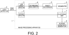
- FIG. 2 is a block diagram showing a schematic configuration of the image processing apparatus 1 according to the first example.
- the image processing apparatus 1 includes a light intensity detector 3, a two-dimensional image generator 4, an object recognizer 5, a distance detector 6, a clustering unit 7, a 3D point cloud data generator 8, and a segmenter 9.
- the information processing apparatus 1 according to the present example may include, for example, processing circuitry.
- the processing circuitry executes, for example, at least one processing operation of the light intensity detector 3, the two-dimensional image generator 4, the object recognizer 5, the distance detector 6, the clustering unit 7, the 3D point cloud data generator 8, and the segmenter 9 of FIG. 2 .
- the light detector 2 emits light to an object, and receives reflected light from the object.
- the light detector 2 may emit light one-dimensionally or two-dimensionally for a scan.
- the light detector 2 may have a function to change the region to which the light is emitted.
- the light detector 2 outputs a distance measuring signal including information on the time at which light is emitted, the scan direction, the scan range, the time at which light is received, and the position at which the light is received.
- the distance measuring signal is sent to the light intensity detector 3 and the distance detector 6.
- the light detector 2 may be, for example, a LiDAR device. In this case, RAW data outputted from the LiDAR device is inputted to the light intensity detector 3 and the distance detector 6.
- the RAW data includes the distance measuring signal.
- the light intensity detector 3 detects at least one of reflected light intensity or ambient light intensity based on the output signal from the light detector 2. As the distance to the object becomes shorter, the intensity of the reflected light from the object increases.
- the ambient light intensity is higher in daytime, during which there is a lot of sunlight, than in night time.
- the two-dimensional image generator 4 generates a two-dimensional image by assigning a color corresponding to the value of the light intensity detected by the light intensity detector 3 to each pixel.
- the object recognizer 5 recognizes an object included in the two-dimensional image.
- the object is, for example, a moving object.
- the object recognizer 5 may recognize the moving object in the two-dimensional image as an object, but does not recognize a motionless object as an object.
- the distance detector 6 detects the distance to the object based on the output signal from the light detector 2 to generate three-dimensional data.
- the three-dimensional data may be three-dimensional point group data in which the locations in space of points, the distances thereto having been measured, are three-dimensionally expressed, or a distance image in which the distances are represented by colors.
- the distance detector 6 detects the distance to an object based on a time difference between the time at which the light reflected on the object is received and the time at which the light is emitted by the light emitter 1.
- the distance detector 6 generates three-dimensional data including a cloud of points, the number of which is proportional to the number of times of light emissions from the light emitter 1.
- the horizontal or vertical distance between point groups is determined by a distance obtained by cutting the viewing angle of the light detector 2 with a constant angular width. If the angular width of the viewing angle is constant, the number of point groups included in an object increases as the distance to the object becomes shorter, and decreases as the distance becomes longer.
- the clustering unit 7 classifies the three-dimensional data into one or more clusters based on the recognition result of the object recognizer 5 and the distance to the object detected by the distance detector 6.
- the clustering unit 7 may provide a label to an object corresponding to each cluster. The label may help the object be recognized easily.
- the image processing apparatus 1 shown in FIG. 2 may or may not include a 3D point cloud data generator 8, which generates data indicating the correspondence relationship among the positions and the distances of point groups and the clusters included in the three-dimensional data. Information on the cluster labels and the types of object corresponding to the point groups may be attached to the data.
- the image processing apparatus 1 shown in FIG. 2 may or may not include a segmenter 9.
- the segmenter 9 classifies the contents of the two-dimensional image into one or more segments based on the object recognized by the object recognizer 5. For example, the segmenter 9 classifies each object (moving object) recognized by the object recognizer 5 into a different segment.
- the clustering unit 7 classifies the three-dimensional data into more than one cluster corresponding to the more than one segment.
- the two-dimensional image generator 4 generates the two-dimensional image based on the RAW data detected by the light detector 2.
- the distance detector 6 also generates the three-dimensional data based on the RAW data detected by the light detector 2.
- the pixel positions of the two-dimensional image correspond to the pixel positions of the three-dimensional data. Therefore, when the object recognizer 5 recognizes an object at specific pixel positions in the two-dimensional image, the pixel positions of the same object in the three-dimensional data may be easily specified.
- the segmenter 9 sets a segment at specific pixel positions in the two-dimensional image, pixel positions of the three-dimensional data corresponding to the segment may be easily specified.
- the clustering unit 7 may perform the clustering of the three-dimensional data easily according to the segments set by the segmenter 9.
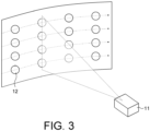
- FIG. 3 schematically illustrates how the light emitter 18 performs scanning using lights emitted to an object.
- the light emitter 18 performs the scanning using a plurality of lights simultaneously emitted from a plurality of laser light sources arranged one-dimensionally or two-dimensionally in the light source unit 11.
- Each circle shown in FIG. 3 schematically represents a beam spot 12 of each laser light.
- the laser lights emitted to the object are reflected on the object and received by the light detector 2.
- the light detector 2 receives the reflected laser lights in the units of pixels.
- the light detector 2 includes light receivers corresponding to a plurality of pixels.
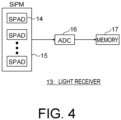
- FIG. 4 is a block diagram schematically showing a configuration of the light receiver 13 of the light detector 2 for one pixel.
- the light receiver 13 includes a silicon photo-multiplier (SiPM) 15 having a plurality of single photon avalanche diodes (SPADs) 14, an analog digital converter (ADC) 16, and a memory 17.
- SiPM silicon photo-multiplier
- SPADs single photon avalanche diodes
- ADC analog digital converter
- Each of the SPADs 14 is able to detect light in the unit of one photon. When a photon is detected, the output voltage of the SPAD 14 decreases. Detecting light, the SPAD 14 "fires.”
- the SiPM 15 includes the plurality of SPADs 14, and as the intensity of light received by the light receiver 13 increases, the number of SPADs 14 that fire increases. As a result, the output voltage of the SiPM 15 decreases.
- the ADC 16 may be able to output a multi-valued digital signal by analog-to-digital converting the output voltage of the SiPM 15.
- the digital signal outputted by the ADC 16 may be called "RAW data" herein.
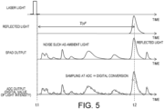
- FIG. 5 is a diagram for explaining a method for detecting the distance to an object using the distance detector 6.
- FIG. 5 shows waveforms of a pulsed light emitted from the light emitter 18, a reflected light from the object, a reflected light received by the light detector 2, and digital signal values (digital values) outputted from the ADC 16.
- the digital values of the digital signals outputted from the ADC 16 correspond to plot positions in FIG. 5 .
- the distance detector 6 detects the distance by a time of flight (ToF) method based on the difference in time between t1 at which the laser light is emitted and t2 at which the light detector 2 receives the reflected light.
- ToF time of flight
- the SPADs 14 for the same pixel may differ in sensitivity for sensing light caused by, for example, manufacturing inconsistency. Furthermore, since not only the reflected light from the object but also ambient light such as sunlight enters each SPAD 14, the waveform of the reflected light received by each SPAD 14 in the light detector 2 may change as the time lapses. The maximum peak position of the reflected light signal indicates the timing at which the number of SPADs 14 firing in the SiPM 15 is the greatest. It may be understood that at this timing the reflected light from the object is received . The distance detector 6 therefore detects the distance to the object according to the difference in time between the timing at which the light signal is emitted and the timing at which the reflected light signal has the maximum peak.
- the distance detector 6 generates the three-dimensional data based on the detected distance.
- the distance to the object is used as depth information.
- FIG. 6 shows an example of the three-dimensional data generated by the distance detector 6.
- the three-dimensional data shown in FIG. 6 is a distance image in which distances are represented by colors. Although the three-dimensional data shown in FIG. 6 is a monochrome image for the sake of convenience, the actual three-dimensional data including the depth information have colors that differ depending on the distance to the object.
- the light intensity detector 3 is able to detect the reflected light intensity based on the output signal from the light detector 2.
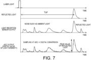
- FIG. 7 is a diagram for explaining the detection of the reflected light intensity. Like FIG. 5 , FIG. 7 shows waveforms of a pulsed light emitted from the light emitter 18, a reflected light from the object, a reflected light received by the light detector 2, and digital signal values (digital values) outputted from the ADC 16. The light detector 2 detects a peak value of the digital signal outputted from the ADC 16 as the reflected light intensity.
- the light intensity detector 3 detects the reflected light intensity of each pixel based on the timing at which the number of SPADs 14 that have detected light is the greatest.
- the two-dimensional image generator 4 generates the two-dimensional image based on the reflected light intensity of each pixel detected by the light intensity detector 3.
- FIG. 8 shows an example of the two-dimensional image generated based on the reflected light intensity. As shown in FIG. 8 , the generated two-dimensional image has luminance that corresponds to the reflected light intensity.
- the light intensity detector 3 is also able to detect the ambient light intensity based on the output signal of the light detector 2.
- FIG. 9 is a diagram for explaining the detection of the ambient light intensity.
- FIG. 9 shows waveforms of a pulsed light emitted from the light emitter 18, a reflected light from the object, a reflected light received by the light detector 2, and digital signal values (digital values) outputted from the ADC 16.
- the ambient light means lights received by the light detector 2 other than the reflected light from the object.
- the main component of the ambient light is sunlight. Since it is likely that the light intensity of the ambient light is smaller than that of the reflected light from the object, the digital signal outputted from the ADC 16 around the peak value is removed from FIG. 9 (the removed portion is indicated by a broken line in FIG. 9 ).
- the light intensity detector 3 detects the ambient light intensity based on the remaining portions of the digital signal outputted from the ADC 16.
- the light intensity detector 3 may detect the ambient light intensity of each pixel except for the timing at which the number of SPADs 14 that are detecting light is the greatest.
- the two-dimensional image generator 4 generates the two-dimensional image based on the ambient light intensity detected for each pixel by the light intensity detector 3.
- FIG. 10 shows an example of the two-dimensional image generated based on the ambient light intensity.
- the ambient light intensity should be very high, it is more difficult to detect the reflected light intensity. Therefore, it is easier to recognize an object using the ambient light intensity.
- the ambient light intensity becomes extremely low, it would be difficult to detect the ambient light intensity. Therefore, it may be easier to recognize an object using the reflected light intensity.
- either of the two types of light intensity which is suitable for the environment, may be used for generating the two-dimensional image.
- FIGs. 11A and 11B show examples of two-dimensional image and three-dimensional data generated by the image processing apparatus 1 shown in FIG. 1 .
- FIG. 11A shows an example of a two-dimensional image G1 generated by the two-dimensional image generator 4 based on the reflected light intensity detected by the light intensity detector 3.
- the object recognizer 5 recognizes one or more objects (for example, moving objects) included in the two-dimensional image G1 by using a pattern matching method, for example.
- FIG. 11B shows an example in which the clustering unit 7 has performed clustering to classify respective objects in the three-dimensional data G2 into different clusters, the objects including those recognized by the object recognizer 5.
- frames are added to two objects (for example, moving objects) included in the three-dimensional data G2, the respective frames indicating different clusters.
- the two-dimensional image data and the three-dimensional data are generated based on the RAW data outputted from the light detector 2, the object is recognized based on the two-dimensional image data, and the clustering is performed on the three-dimensional data based on the recognition result.
- the clustering of the three-dimensional data in this manner may be easier, faster, and more accurate than the clustering of the three-dimensional data performed by directly recognizing the object in the three-dimensional data.
- the moving object may be tracked or recognized, for example.
- An image processing apparatus 1a according to a second example has a function to adjust the contrast of the two-dimensional image.
- FIG. 12 is a block diagram showing a schematic configuration of the image processing apparatus 1a according to the second example.
- elements that are common to those in FIG. 2 have the same reference numerals. In the following descriptions, differences between the first and the second example will be mainly described.
- the image processing apparatus 1a shown in FIG. 12 includes a contrast adder 21 in addition to the elements in the block diagram of the image processing apparatus 1 in FIG. 2 .
- the contrast adder 21 adds contrast information to the light intensity data detected by the light intensity detector 3.
- the two-dimensional image generator 4 generates the two-dimensional image based on the light intensity data to which the contrast information is added.
- the contrast adder adds the contrast information to the light intensity data so as to emphasize the contrast between the object (moving object) and the surroundings in the two-dimensional image.
- the contrast information is used to instruct how the contrast is emphasized in the pixel region of the object (moving object).
- contrast adder 21 By providing the contrast adder 21, it is possible to show the object (moving object) in the two-dimensional image in white, and to show the background portion around the object (moving object) in black, so as to help the object recognizer 5 recognize the object (moving object) more easily.
- FIG. 13 is a block diagram showing a schematic configuration of an image processing apparatus 1b according to a first modification of the second example.
- elements common to those in FIG. 12 have the same reference numerals. In the following descriptions, differences will be mainly described.
- the image processing apparatus 1b shown in FIG. 13 includes a difference detector 22.
- the difference detector 22 detects a moving object by obtaining a difference between a plurality of three-dimensional data sets generated at different points in time. For example, the difference detector 22 easily detects only a point group of the moving object by obtaining a difference between two three-dimensional data sets generated at different points in time.
- the difference detector 22 it is possible to extract only the point group of the moving object from the three-dimensional data detected by the distance detector 6 to generate new three-dimensional data, thereby reducing the data amount of the three-dimensional data. As a result, the load of the clustering performed by the clustering unit 7 in a later stage may be reduced.
- the contrast adder 21 adds the contrast information to the light intensity data so as to emphasize the presence of the moving object in the two-dimensional image detected by the difference detector 22.
- the two-dimensional image generator 4 may be able to emphasize the contrast of the pixel region in the moving object included in the two-dimensional image.
- FIGs. 14A to 14D show examples of image generated by the image processing apparatus 1a illustrated in FIG. 12 .
- FIG. 14A shows a two-dimensional image G4 generated before the contrast adder 21 adds the contrast information to the light intensity data.
- FIG. 14B shows a two-dimensional image G5 in which the contrast around the moving object is emphasized by the contrast adder 21.
- FIG. 14C shows a two-dimensional image G6 obtained after the two-dimensional image G5 is divided into segments.
- FIG. 14D shows a three-dimensional data G7 obtained after clustering is performed.
- the difference detector 22 detects the moving object included in the three-dimensional data by detecting a difference between a plurality of three-dimensional data sets detected by the distance detector 6.
- the contrast adder 21 adds the contrast information to the light intensity data so as to emphasize the contrast between the moving object detected by the difference detector 22 and the background.
- the two-dimensional image generator 4 therefore generates the two-dimensional image G5 in which the moving object is emphasized as shown in FIG. 14B .
- the two-dimensional image G5 is blacked out except for the pixel regions including moving objects.
- the contrast information added by the contrast adder 21 includes, for example, information instructing that the luminance of pixels around high-luminance pixels (such as white-based pixels) in a pixel region including a moving object should be reduced so that the they have a dark color (black-based color), and that the luminance of pixels around low-luminance pixels (such as black-based pixels) in the two-dimensional image should be increased so that the pixels have a light color (white-based color).
- the two-dimensional image generator 4 generates the two-dimensional image G5, for example.
- the object recognizer 5 recognizes the moving object from the two-dimensional image G5 in which the contrast between the moving object and the surrounding portions is emphasized.
- the segmenter 9 put each moving object recognized by object recognizer 5 into a segment.
- the two-dimensional image G6 shown in FIG. 14C has two segments. The contrast is more emphasized in the two-dimensional image G6 than in the two-dimensional image G5.
- the clustering unit performs clustering on the three-dimensional data so as to be associated with the pixel positions in each segment of the two-dimensional image G5.
- the three-dimensional data G7 shown in FIG. 14D has two clusters corresponding to the two segments in the two-dimensional image G6 shown in FIG. 14C .
- the accuracy in recognition of the object may be improved. Furthermore, by providing the difference detector 22, it is possible to detect the moving object in the three-dimensional data easily.
- the contrast adder 21 uses the detection result of the difference detector 22 to emphasize the contrast between the moving object and the surrounding regions in the two-dimensional image. Therefore, the object recognizer 5 may be able to recognize the moving object included in the two-dimensional image with high accuracy, and the clustering unit 7 may be able to perform the clustering of each moving object in the three-dimensional data with high accuracy.
- each object included in a two-dimensional image is not always the same.
- an object that is closer is displayed bigger, and an object that is more distant is displayed smaller. Therefore, there is a possibility that an object that is distantly located may not be correctly recognized from the two-dimensional image.
- each object is expressed as a point group having the same contour size regardless of the distance to the object, but the density of each point group differs depending on the distance. Therefore, a third example is intended to recognize each object in a two-dimensional image with high accuracy regardless of the distance to the object.
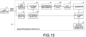
- FIG. 15 is a block diagram showing a schematic configuration of an image processing apparatus 1c according to the third example.
- elements common to those in FIG. 13 have the same reference numerals. In the following descriptions, differences will be mainly described.
- the image processing apparatus 1c shown in FIG. 15 includes a magnification adjuster 23.
- the magnification adjuster 23 Based on moving objects detected by the difference detector 22 and the distances to the moving objects detected by the distance detector 6, the magnification adjuster 23 adjust the sizes of the moving objects in the two-dimensional image, which locate at the same distance. In other words, the magnification adjuster 23 adjusts the sizes of moving objects in the two-dimensional image, the distances to the moving objects differing from each other, to sizes determined on the assumption that the distances to them are the same. This makes it easier to recognize an object located in the distance.
- the magnification adjuster 23 adjusts the sizes of objects to sizes that are obtained by assuming that the objects are at the same distance based on the sizes of the objects in the two-dimensional image and the distances to the objects detected by the distance detector 6. For example, if the distance to an object is 100 m and the distance to another object is 1 m, the magnification adjuster 23 may adjust the sizes of the objects to sizes obtained by assuming that the distance to both of the objects is 10 m.
- the object recognizer 5 recognizes the objects based on the two-dimensional image including the objects of which the sizes have been adjusted by the magnification adjuster 23.
- the clustering unit 7 performs the clustering of the moving objects included in the three-dimensional data based on the moving objects recognized by the object recognizer 5 and the two-dimensional image before being subjected to the adjustment performed by the magnification adjuster 23.
- FIGs. 16A to 16D show examples of images generated by the image processing apparatus 1c shown in FIG. 15 .
- FIG. 16A shows a two-dimensional image G11 before being subjected to contrast adjustment.
- FIG. 16B shows a two-dimensional image G12 in which the contrast between two moving objects and the surrounding regions is emphasized, the two objects being located at different distances (60 m and 15 m) and detected by the difference detector 22.
- the two-dimensional image G12 includes a moving object (vehicle), the distance thereto being 60 m, and a moving object (person), the distance thereto being 15 m.
- FIG. 16C shows a two-dimensional image G13 after being subjected to magnification adjustment performed by the magnification adjuster 23.
- the magnification adjuster 23 adjusts the sizes of the two moving objects included in the two-dimensional image G12 by assuming that the distance to the two moving objects is 30 m, for example, and generates the two-dimensional image G13 including the adjusted moving objects.
- the moving objects in the two-dimensional image G13 have sizes that are determined by assuming that they are at the same distance. This makes it easier for the object recognizer 5 to recognize the moving objects.
- FIG. 16D shows a two-dimensional image G14 in which the moving objects are classified into different segments by the segmenter 9 based on the recognition result of the object recognizer 5. With the two-dimensional image G14, the clustering operation may be performed with high accuracy on the three-dimensional data by the clustering unit 7.
- the sizes of objects (moving objects) included in a two-dimensional image are adjusted by the magnification adjuster 23 so that the object recognizer 5 may accurately recognize the objects (moving objects) even if the distances to the objects are different. This improves the recognition accuracy of the object recognizer 5.
- the three-dimensional data generated based on the distances to the moving objects detected by the detector 6 also includes point groups of various objects other than those of the moving objects.
- a function be provided to delete point groups other than those of the moving objects as noise.
- FIG. 17 is a block diagram showing a schematic configuration of an image processing apparatus 1d according to a fourth example.
- elements common to those of FIG. 2 have the same reference numerals. In the following descriptions, differences will be mainly described.
- the image processing apparatus 1d shown in FIG. 17 includes a noise remover 24.
- the noise remover 24 removes noise included in the three-dimensional data generated based on the distances detected by the distance detector 6. The removal of noise from the three-dimensional data is performed by the noise remover 24 based on the objects recognized by the object recognizer 5, for example.
- the noise remover 24 has data of contour sizes of point groups (such as vehicle or person) associated with the recognition results of the object recognizer 5, and compare the data with the point groups of the objects in the three-dimensional data.
- the noise remover 24 removes as noise point groups that are not in the data.
- the clustering unit 7 performs the clustering operation on each object included in the three-dimensional data from which noise has been removed by the noise remover 24.
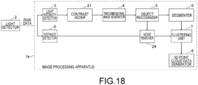
- FIG. 18 is a block diagram showing a schematic configuration of an image processing apparatus 1e according to a modification of the image processing apparatus 1d shown in FIG. 17 .
- the image processing apparatus 1e shown in FIG. 18 includes a noise remover 24.
- the noise remover 24 may also be added to the image processing apparatus 1b shown in FIG. 13 or the image processing apparatus 1c shown in FIG. 15 .
- the removal of noise included in the three-dimensional data based on the object recognized by the object recognizer 5 makes it easy for the clustering unit 7 to perform the clustering operation.
- the object recognizer 5 recognizes objects in the entire regions of the two-dimensional image.
- a region of interest ROI may be set in a part of the two-dimensional image and objects may be recognized in the ROI.
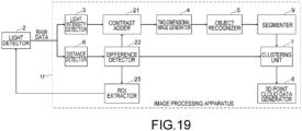
- FIG. 19 is a block diagram showing a schematic configuration of an image processing apparatus If according to a fifth example.
- elements common to FIG. 2 have the same reference numerals. In the following descriptions, differences will be mainly described.
- the image processing apparatus 1f shown in FIG. 19 includes an ROI extractor 25.
- the ROI extractor 25 extracts a pixel region including the moving object detected by the difference detector 22 in the two-dimensional image as an ROI.
- the light emitter 18 controls the scanning region of the light emitted to the object based on the ROI detected by the ROI extractor 25.
- the light emitter 18 concentratedly emits light to the ROI to receive the reflected light from the object in the ROI.
- the distance to the object in the ROI may be detected more accurately, and therefore the shape and the size of the object may be obtained in more detail.
- the contrast adder 21 adds contrast information to the light intensity data so that the contrast between the moving object and the surrounding regions in the two-dimensional image corresponding to the ROI may be emphasized.
- the contrast adder 21 adds contrast information to the light intensity data for changing the color of the pixel regions other than the pixel region corresponding to the ROI to be a monotone color (for example, black).
- the two-dimensional image generator 4 After the light detector 2 controls the scanning region of the light emitted to the object based on the ROI extracted by the ROI extractor 25, the two-dimensional image generator 4 generates a two-dimensional image corresponding to the ROI based on the reflected light received by the light detector 2. Therefore, the two-dimensional image generated by the two-dimensional image generator 4 may have a detailed image in the ROI. Furthermore, in the two-dimensional image generated by the two-dimensional image generator 4, the contrast between the object (moving object) and the surrounding regions is emphasized based on the contrast information added by the contrast adder 21.
- the object recognizer 5 recognizes the object in the ROI in the two-dimensional image. As a result, the object may be recognized rapidly and accurately.
- the configuration in FIG. 19 is obtained by adding the ROI extractor 25 to the configuration of FIG. 13
- the ROI extractor 25 may be added to the configuration shown in FIG. 15 .
- the magnification may be performed more accurately, and the recognition accuracy of the object recognizer 5 may be improved.
- the noise remover 24 shown in FIG. 17 may further be added.
- a region including the moving object detected by the difference detector 22 is extracted as an ROI, and the light from the light emitter 18 is concentratedly emitted to the ROI to detect the shape and the size of the moving object in the ROI more accurately.
- the emission of light to a limited region in which the moving object is present enables the clustering of the three-dimensional data to be performed more efficiently.
Landscapes
- Engineering & Computer Science (AREA)
- Physics & Mathematics (AREA)
- General Physics & Mathematics (AREA)
- Theoretical Computer Science (AREA)
- Radar, Positioning & Navigation (AREA)
- Remote Sensing (AREA)
- Multimedia (AREA)
- Computer Vision & Pattern Recognition (AREA)
- Computer Networks & Wireless Communication (AREA)
- Electromagnetism (AREA)
- Artificial Intelligence (AREA)
- Health & Medical Sciences (AREA)
- Computing Systems (AREA)
- Databases & Information Systems (AREA)
- Evolutionary Computation (AREA)
- General Health & Medical Sciences (AREA)
- Medical Informatics (AREA)
- Software Systems (AREA)
- Optics & Photonics (AREA)
- Length Measuring Devices By Optical Means (AREA)
- Optical Radar Systems And Details Thereof (AREA)
- Measurement Of Optical Distance (AREA)
Abstract
Description
- One or more examples of the present invention relate to an apparatus.
- As the LiDAR (Light Detection & Ranging) technology has been improving, it is expected that the importance of the recognition and classification techniques for three-dimensional data, as well as two-dimensional images, will be increased.
- However, at the present stage, it is difficult to efficiently process three-dimensional data as compared to two-dimensional images, since the depth information added to the three-dimensional data increases the calculation amount, thereby complicating the processing, and training data for three-dimensional data is lacking.
-
-
FIG. 1 is a block diagram of an image processing system including an image processing apparatus according to a first example. -
FIG. 2 is a block diagram showing a schematic configuration of an image processing apparatus according to a first example. -
FIG. 3 schematically illustrates how a light detector performs scanning using lights emitted to an object. -
FIG. 4 is a block diagram schematically showing a configuration of a light receiver of the light detector for one pixel. -
FIG. 5 is a diagram for explaining a method of detecting a distance to an object using a distance detector. -
FIG. 6 shows an example of three-dimensional data generated by the distance detector. -
FIG. 7 is a diagram for explaining the detection of reflected light intensity. -
FIG. 8 shows an example of two-dimensional image generated based on the reflected light intensity. -
FIG. 9 is a diagram for explaining the detection of ambient light intensity. -
FIG. 10 shows an example of two-dimensional image generated based on the ambient light intensity. -
FIGs. 11A and 11B show examples of two-dimensional image and three-dimensional data generated by the image processing apparatus -
FIG. 12 is a block diagram showing a schematic configuration of an image processing apparatus according to a second example. -
FIG. 13 is a block diagram showing a schematic configuration of an image processing apparatus according to a first modification of the first example. -
FIGs. 14A to 14D show examples of image generated by the image processing apparatus shown inFIG. 12 . -
FIG. 15 is a block diagram showing a schematic configuration of an image processing apparatus according to a third example. -
FIGs. 16A to 16D show examples of images generated by the image processing apparatus shown inFIG. 15 . -
FIG. 17 is a block diagram showing a schematic configuration of an image processing apparatus according to a fourth example. -
FIG. 18 is a block diagram showing a schematic configuration of an image processing apparatus according to a modification ofFIG. 17 . -
FIG. 19 is a block diagram showing a schematic configuration of an image processing apparatus according to a fifth example. - According to an example, an image processing apparatus comprising processing circuitry, the processing circuitry is configure to detect light intensity data including at least one of a reflected light intensity of light reflected on an object or an ambient light intensity based on a reception signal corresponding to a reflected light from the object, generate a two-dimensional image based on the light intensity data, recognize the object in the two-dimensional image, generate three-dimensional data by detecting a distance to the object based on the reception signal, and classify the three-dimensional data into one or more clusters based on the recognized object and the distance to the detected object.
- Examples of an image processing apparatus will now be described below with reference to the accompanying drawings. In the following descriptions, major components of the image processing apparatus will be mainly explained. However, the image processing apparatus may have a component or a function that is not described herein or illustrated in the drawings. The following descriptions do not exclude such a component or function.
-
FIG. 1 is a block diagram of animage processing system 10 including animage processing apparatus 1 according to a first example. Theimage processing system 10 shown inFIG. 1 includes alight emitter 18, alight detector 2, and theimage processing apparatus 1. - The
light emitter 18 includes alight source unit 11 and alight scanner 19. Thelight source unit 11 intermittently emits light pulse signals linearly or two-dimensionally. - The
light scanner 19 scans the direction of the light pulse signals emitted from thelight source unit 11 one dimensionally or two dimensionally. Therefore, it is possible to emit the light pulse signals to anobject 30 in a three-dimensional space. - The
light detector 2 receives reflected light signals of the light pulse signals emitted to theobject 30. Thelight detector 2 includes a plurality oflight receivers 13. Thelight detector 2 detects reflected light signals that enter a two-dimensional region, for example. A minimum unit in the two-dimensional region of thelight detector 2 for receiving the reflected light signals is called "pixel" herein. Thelight detector 2 includes more than onelight receiver 13 configured to receive the reflected light signal in each pixel. - Based on the reflected light signals received by the
light detector 2, theimage processing apparatus 1 detects the distance to theobject 30 and generates a two-dimensional image including luminance information around theobject 30 and three-dimensional data including distance information of theobject 30. -
FIG. 2 is a block diagram showing a schematic configuration of theimage processing apparatus 1 according to the first example. Theimage processing apparatus 1 includes alight intensity detector 3, a two-dimensional image generator 4, an object recognizer 5, adistance detector 6, aclustering unit 7, a 3D pointcloud data generator 8, and asegmenter 9. Theinformation processing apparatus 1 according to the present example may include, for example, processing circuitry. The processing circuitry executes, for example, at least one processing operation of thelight intensity detector 3, the two-dimensional image generator 4, the object recognizer 5, thedistance detector 6, theclustering unit 7, the 3D pointcloud data generator 8, and thesegmenter 9 ofFIG. 2 . - The
light detector 2 emits light to an object, and receives reflected light from the object. Thelight detector 2 may emit light one-dimensionally or two-dimensionally for a scan. Thelight detector 2 may have a function to change the region to which the light is emitted. Thelight detector 2 outputs a distance measuring signal including information on the time at which light is emitted, the scan direction, the scan range, the time at which light is received, and the position at which the light is received. The distance measuring signal is sent to thelight intensity detector 3 and thedistance detector 6. Thelight detector 2 may be, for example, a LiDAR device. In this case, RAW data outputted from the LiDAR device is inputted to thelight intensity detector 3 and thedistance detector 6. The RAW data includes the distance measuring signal. - The
light intensity detector 3 detects at least one of reflected light intensity or ambient light intensity based on the output signal from thelight detector 2. As the distance to the object becomes shorter, the intensity of the reflected light from the object increases. The ambient light intensity is higher in daytime, during which there is a lot of sunlight, than in night time. - The two-
dimensional image generator 4 generates a two-dimensional image by assigning a color corresponding to the value of the light intensity detected by thelight intensity detector 3 to each pixel. - The
object recognizer 5 recognizes an object included in the two-dimensional image. The object is, for example, a moving object. Thus, theobject recognizer 5 may recognize the moving object in the two-dimensional image as an object, but does not recognize a motionless object as an object. - The
distance detector 6 detects the distance to the object based on the output signal from thelight detector 2 to generate three-dimensional data. The three-dimensional data may be three-dimensional point group data in which the locations in space of points, the distances thereto having been measured, are three-dimensionally expressed, or a distance image in which the distances are represented by colors. For example, thedistance detector 6 detects the distance to an object based on a time difference between the time at which the light reflected on the object is received and the time at which the light is emitted by thelight emitter 1. Thedistance detector 6 generates three-dimensional data including a cloud of points, the number of which is proportional to the number of times of light emissions from thelight emitter 1. In the process of adjusting the direction of light emissions from thelight detector 2 one-dimensionally or two-dimensionally, as the number of light emissions increases, the number of point groups included in the three-dimensional data increases, and as the number of light emissions decreases, the number of point groups decreases. If the interval between light emissions is constant, the horizontal or vertical distance between point groups is determined by a distance obtained by cutting the viewing angle of thelight detector 2 with a constant angular width. If the angular width of the viewing angle is constant, the number of point groups included in an object increases as the distance to the object becomes shorter, and decreases as the distance becomes longer. - In the three-dimensional data generated by the
distance detector 6, the volume of the total point groups of the same object does not change as the distance from the light detector changes, but the density of the point groups becomes higher (the number of point groups included in the object becomes greater) as the distance to the object is shorter, and the density becomes lower (the number of point groups included in the object becomes smaller) as the distance to the object is longer. Each of the point groups in the three-dimensional data corresponds to a different object. Each point in the point group indicates the position at which the object reflects light. - The
clustering unit 7 classifies the three-dimensional data into one or more clusters based on the recognition result of theobject recognizer 5 and the distance to the object detected by thedistance detector 6. Theclustering unit 7 may provide a label to an object corresponding to each cluster. The label may help the object be recognized easily. - The
image processing apparatus 1 shown inFIG. 2 may or may not include a 3D pointcloud data generator 8, which generates data indicating the correspondence relationship among the positions and the distances of point groups and the clusters included in the three-dimensional data. Information on the cluster labels and the types of object corresponding to the point groups may be attached to the data. - The
image processing apparatus 1 shown inFIG. 2 may or may not include asegmenter 9. Thesegmenter 9 classifies the contents of the two-dimensional image into one or more segments based on the object recognized by theobject recognizer 5. For example, thesegmenter 9 classifies each object (moving object) recognized by theobject recognizer 5 into a different segment. Theclustering unit 7 classifies the three-dimensional data into more than one cluster corresponding to the more than one segment. - More specifically, the two-
dimensional image generator 4 generates the two-dimensional image based on the RAW data detected by thelight detector 2. Thedistance detector 6 also generates the three-dimensional data based on the RAW data detected by thelight detector 2. The pixel positions of the two-dimensional image correspond to the pixel positions of the three-dimensional data. Therefore, when theobject recognizer 5 recognizes an object at specific pixel positions in the two-dimensional image, the pixel positions of the same object in the three-dimensional data may be easily specified. Similarly, when thesegmenter 9 sets a segment at specific pixel positions in the two-dimensional image, pixel positions of the three-dimensional data corresponding to the segment may be easily specified. Thus, theclustering unit 7 may perform the clustering of the three-dimensional data easily according to the segments set by thesegmenter 9. -
FIG. 3 schematically illustrates how thelight emitter 18 performs scanning using lights emitted to an object. Thelight emitter 18 performs the scanning using a plurality of lights simultaneously emitted from a plurality of laser light sources arranged one-dimensionally or two-dimensionally in thelight source unit 11. Each circle shown inFIG. 3 schematically represents abeam spot 12 of each laser light. The laser lights emitted to the object are reflected on the object and received by thelight detector 2. Thelight detector 2 receives the reflected laser lights in the units of pixels. Thelight detector 2 includes light receivers corresponding to a plurality of pixels. -
FIG. 4 is a block diagram schematically showing a configuration of thelight receiver 13 of thelight detector 2 for one pixel. Thelight receiver 13 includes a silicon photo-multiplier (SiPM) 15 having a plurality of single photon avalanche diodes (SPADs) 14, an analog digital converter (ADC) 16, and amemory 17. - Each of the
SPADs 14 is able to detect light in the unit of one photon. When a photon is detected, the output voltage of theSPAD 14 decreases. Detecting light, theSPAD 14 "fires." TheSiPM 15 includes the plurality ofSPADs 14, and as the intensity of light received by thelight receiver 13 increases, the number ofSPADs 14 that fire increases. As a result, the output voltage of theSiPM 15 decreases. Thus, theADC 16 may be able to output a multi-valued digital signal by analog-to-digital converting the output voltage of theSiPM 15. The digital signal outputted by theADC 16 may be called "RAW data" herein. -
FIG. 5 is a diagram for explaining a method for detecting the distance to an object using thedistance detector 6.FIG. 5 shows waveforms of a pulsed light emitted from thelight emitter 18, a reflected light from the object, a reflected light received by thelight detector 2, and digital signal values (digital values) outputted from theADC 16. The digital values of the digital signals outputted from theADC 16 correspond to plot positions inFIG. 5 . - The
distance detector 6 detects the distance by a time of flight (ToF) method based on the difference in time between t1 at which the laser light is emitted and t2 at which thelight detector 2 receives the reflected light. - The
SPADs 14 for the same pixel may differ in sensitivity for sensing light caused by, for example, manufacturing inconsistency. Furthermore, since not only the reflected light from the object but also ambient light such as sunlight enters eachSPAD 14, the waveform of the reflected light received by eachSPAD 14 in thelight detector 2 may change as the time lapses. The maximum peak position of the reflected light signal indicates the timing at which the number ofSPADs 14 firing in theSiPM 15 is the greatest. It may be understood that at this timing the reflected light from the object is received . Thedistance detector 6 therefore detects the distance to the object according to the difference in time between the timing at which the light signal is emitted and the timing at which the reflected light signal has the maximum peak. - The
distance detector 6 generates the three-dimensional data based on the detected distance. In the three-dimensional data generated by thedistance detector 6, the distance to the object is used as depth information.FIG. 6 shows an example of the three-dimensional data generated by thedistance detector 6. The three-dimensional data shown inFIG. 6 is a distance image in which distances are represented by colors. Although the three-dimensional data shown inFIG. 6 is a monochrome image for the sake of convenience, the actual three-dimensional data including the depth information have colors that differ depending on the distance to the object. - The
light intensity detector 3 according to the first example is able to detect the reflected light intensity based on the output signal from thelight detector 2.FIG. 7 is a diagram for explaining the detection of the reflected light intensity. LikeFIG. 5 ,FIG. 7 shows waveforms of a pulsed light emitted from thelight emitter 18, a reflected light from the object, a reflected light received by thelight detector 2, and digital signal values (digital values) outputted from theADC 16. Thelight detector 2 detects a peak value of the digital signal outputted from theADC 16 as the reflected light intensity. - As described above, the
light intensity detector 3 detects the reflected light intensity of each pixel based on the timing at which the number ofSPADs 14 that have detected light is the greatest. In this case, the two-dimensional image generator 4 generates the two-dimensional image based on the reflected light intensity of each pixel detected by thelight intensity detector 3. -
FIG. 8 shows an example of the two-dimensional image generated based on the reflected light intensity. As shown inFIG. 8 , the generated two-dimensional image has luminance that corresponds to the reflected light intensity. - The
light intensity detector 3 according to the first example is also able to detect the ambient light intensity based on the output signal of thelight detector 2.FIG. 9 is a diagram for explaining the detection of the ambient light intensity.FIG. 9 shows waveforms of a pulsed light emitted from thelight emitter 18, a reflected light from the object, a reflected light received by thelight detector 2, and digital signal values (digital values) outputted from theADC 16. - The ambient light means lights received by the
light detector 2 other than the reflected light from the object. The main component of the ambient light is sunlight. Since it is likely that the light intensity of the ambient light is smaller than that of the reflected light from the object, the digital signal outputted from theADC 16 around the peak value is removed fromFIG. 9 (the removed portion is indicated by a broken line inFIG. 9 ). Thelight intensity detector 3 detects the ambient light intensity based on the remaining portions of the digital signal outputted from theADC 16. - The
light intensity detector 3 may detect the ambient light intensity of each pixel except for the timing at which the number ofSPADs 14 that are detecting light is the greatest. In this case, the two-dimensional image generator 4 generates the two-dimensional image based on the ambient light intensity detected for each pixel by thelight intensity detector 3. -
FIG. 10 shows an example of the two-dimensional image generated based on the ambient light intensity. As may be understood fromFIG. 9 , since information on the pixels in which the reflected light intensity is high is excluded inFIG. 10 , it may be rather difficult to view the moving object in the two-dimensional image, but it may be easier to view information in the background. During the daytime in summer under a blazing sun, in which the ambient light intensity should be very high, it is more difficult to detect the reflected light intensity. Therefore, it is easier to recognize an object using the ambient light intensity. On the other hand, during the nighttime, in which the ambient light intensity becomes extremely low, it would be difficult to detect the ambient light intensity. Therefore, it may be easier to recognize an object using the reflected light intensity. Thus, either of the two types of light intensity, which is suitable for the environment, may be used for generating the two-dimensional image. -
FIGs. 11A and 11B show examples of two-dimensional image and three-dimensional data generated by theimage processing apparatus 1 shown inFIG. 1 .FIG. 11A shows an example of a two-dimensional image G1 generated by the two-dimensional image generator 4 based on the reflected light intensity detected by thelight intensity detector 3. Theobject recognizer 5 recognizes one or more objects (for example, moving objects) included in the two-dimensional image G1 by using a pattern matching method, for example.FIG. 11B shows an example in which theclustering unit 7 has performed clustering to classify respective objects in the three-dimensional data G2 into different clusters, the objects including those recognized by theobject recognizer 5. InFIG. 11B , frames are added to two objects (for example, moving objects) included in the three-dimensional data G2, the respective frames indicating different clusters. - As described above, in the first example, the two-dimensional image data and the three-dimensional data are generated based on the RAW data outputted from the
light detector 2, the object is recognized based on the two-dimensional image data, and the clustering is performed on the three-dimensional data based on the recognition result. The clustering of the three-dimensional data in this manner may be easier, faster, and more accurate than the clustering of the three-dimensional data performed by directly recognizing the object in the three-dimensional data. After the clustering of the three-dimensional data is performed, the moving object may be tracked or recognized, for example. - An
image processing apparatus 1a according to a second example has a function to adjust the contrast of the two-dimensional image. -
FIG. 12 is a block diagram showing a schematic configuration of theimage processing apparatus 1a according to the second example. InFIG. 12 , elements that are common to those inFIG. 2 have the same reference numerals. In the following descriptions, differences between the first and the second example will be mainly described. - The
image processing apparatus 1a shown inFIG. 12 includes acontrast adder 21 in addition to the elements in the block diagram of theimage processing apparatus 1 inFIG. 2 . Thecontrast adder 21 adds contrast information to the light intensity data detected by thelight intensity detector 3. The two-dimensional image generator 4 generates the two-dimensional image based on the light intensity data to which the contrast information is added. For example, the contrast adder adds the contrast information to the light intensity data so as to emphasize the contrast between the object (moving object) and the surroundings in the two-dimensional image. The contrast information is used to instruct how the contrast is emphasized in the pixel region of the object (moving object). By providing thecontrast adder 21, it is possible to show the object (moving object) in the two-dimensional image in white, and to show the background portion around the object (moving object) in black, so as to help theobject recognizer 5 recognize the object (moving object) more easily. -
FIG. 13 is a block diagram showing a schematic configuration of animage processing apparatus 1b according to a first modification of the second example. InFIG. 13 , elements common to those inFIG. 12 have the same reference numerals. In the following descriptions, differences will be mainly described. - The
image processing apparatus 1b shown inFIG. 13 includes adifference detector 22. Thedifference detector 22 detects a moving object by obtaining a difference between a plurality of three-dimensional data sets generated at different points in time. For example, thedifference detector 22 easily detects only a point group of the moving object by obtaining a difference between two three-dimensional data sets generated at different points in time. - By providing the
difference detector 22, it is possible to extract only the point group of the moving object from the three-dimensional data detected by thedistance detector 6 to generate new three-dimensional data, thereby reducing the data amount of the three-dimensional data. As a result, the load of the clustering performed by theclustering unit 7 in a later stage may be reduced. - The
contrast adder 21 adds the contrast information to the light intensity data so as to emphasize the presence of the moving object in the two-dimensional image detected by thedifference detector 22. As a result, the two-dimensional image generator 4 may be able to emphasize the contrast of the pixel region in the moving object included in the two-dimensional image. -
FIGs. 14A to 14D show examples of image generated by theimage processing apparatus 1a illustrated inFIG. 12 .FIG. 14A shows a two-dimensional image G4 generated before thecontrast adder 21 adds the contrast information to the light intensity data.FIG. 14B shows a two-dimensional image G5 in which the contrast around the moving object is emphasized by thecontrast adder 21.FIG. 14C shows a two-dimensional image G6 obtained after the two-dimensional image G5 is divided into segments.FIG. 14D shows a three-dimensional data G7 obtained after clustering is performed. - The
difference detector 22 detects the moving object included in the three-dimensional data by detecting a difference between a plurality of three-dimensional data sets detected by thedistance detector 6. Thecontrast adder 21 adds the contrast information to the light intensity data so as to emphasize the contrast between the moving object detected by thedifference detector 22 and the background. The two-dimensional image generator 4 therefore generates the two-dimensional image G5 in which the moving object is emphasized as shown inFIG. 14B . The two-dimensional image G5 is blacked out except for the pixel regions including moving objects. - The contrast information added by the
contrast adder 21 includes, for example, information instructing that the luminance of pixels around high-luminance pixels (such as white-based pixels) in a pixel region including a moving object should be reduced so that the they have a dark color (black-based color), and that the luminance of pixels around low-luminance pixels (such as black-based pixels) in the two-dimensional image should be increased so that the pixels have a light color (white-based color). Receiving the contrast information, the two-dimensional image generator 4 generates the two-dimensional image G5, for example. Theobject recognizer 5 recognizes the moving object from the two-dimensional image G5 in which the contrast between the moving object and the surrounding portions is emphasized. Thesegmenter 9 put each moving object recognized byobject recognizer 5 into a segment. The two-dimensional image G6 shown inFIG. 14C has two segments. The contrast is more emphasized in the two-dimensional image G6 than in the two-dimensional image G5. The clustering unit performs clustering on the three-dimensional data so as to be associated with the pixel positions in each segment of the two-dimensional image G5. The three-dimensional data G7 shown inFIG. 14D has two clusters corresponding to the two segments in the two-dimensional image G6 shown inFIG. 14C . - As described above, as the contrast between an object and surrounding regions in the two-dimensional image is emphasized in the second example, the accuracy in recognition of the object may be improved. Furthermore, by providing the
difference detector 22, it is possible to detect the moving object in the three-dimensional data easily. Thecontrast adder 21 uses the detection result of thedifference detector 22 to emphasize the contrast between the moving object and the surrounding regions in the two-dimensional image. Therefore, theobject recognizer 5 may be able to recognize the moving object included in the two-dimensional image with high accuracy, and theclustering unit 7 may be able to perform the clustering of each moving object in the three-dimensional data with high accuracy. - The distance to each object included in a two-dimensional image is not always the same. In the two-dimensional image, an object that is closer is displayed bigger, and an object that is more distant is displayed smaller. Therefore, there is a possibility that an object that is distantly located may not be correctly recognized from the two-dimensional image. On the other hand, in three-dimensional data, each object is expressed as a point group having the same contour size regardless of the distance to the object, but the density of each point group differs depending on the distance. Therefore, a third example is intended to recognize each object in a two-dimensional image with high accuracy regardless of the distance to the object.
-
FIG. 15 is a block diagram showing a schematic configuration of animage processing apparatus 1c according to the third example. InFIG. 15 , elements common to those inFIG. 13 have the same reference numerals. In the following descriptions, differences will be mainly described. - In addition to the configuration shown in
FIG. 13 , theimage processing apparatus 1c shown inFIG. 15 includes amagnification adjuster 23. Based on moving objects detected by thedifference detector 22 and the distances to the moving objects detected by thedistance detector 6, themagnification adjuster 23 adjust the sizes of the moving objects in the two-dimensional image, which locate at the same distance. In other words, themagnification adjuster 23 adjusts the sizes of moving objects in the two-dimensional image, the distances to the moving objects differing from each other, to sizes determined on the assumption that the distances to them are the same. This makes it easier to recognize an object located in the distance. - The
magnification adjuster 23 adjusts the sizes of objects to sizes that are obtained by assuming that the objects are at the same distance based on the sizes of the objects in the two-dimensional image and the distances to the objects detected by thedistance detector 6. For example, if the distance to an object is 100 m and the distance to another object is 1 m, themagnification adjuster 23 may adjust the sizes of the objects to sizes obtained by assuming that the distance to both of the objects is 10 m. - The
object recognizer 5 recognizes the objects based on the two-dimensional image including the objects of which the sizes have been adjusted by themagnification adjuster 23. - If a new two-dimensional image is generated, in which the size of each object has been adjusted by the
magnification adjuster 23, the pixel positions in the new two-dimensional image do not conform to the pixel positions in the three-dimensional data generated by thedistance detector 6. Therefore, the two-dimensional image before being subjected to the adjustment of the size of each object by themagnification adjuster 23 should be used for the operations performed by thesegmenter 9 and theclustering unit 7. Thus, theclustering unit 7 performs the clustering of the moving objects included in the three-dimensional data based on the moving objects recognized by theobject recognizer 5 and the two-dimensional image before being subjected to the adjustment performed by themagnification adjuster 23. -
FIGs. 16A to 16D show examples of images generated by theimage processing apparatus 1c shown inFIG. 15 .FIG. 16A shows a two-dimensional image G11 before being subjected to contrast adjustment.FIG. 16B shows a two-dimensional image G12 in which the contrast between two moving objects and the surrounding regions is emphasized, the two objects being located at different distances (60 m and 15 m) and detected by thedifference detector 22. The two-dimensional image G12 includes a moving object (vehicle), the distance thereto being 60 m, and a moving object (person), the distance thereto being 15 m.FIG. 16C shows a two-dimensional image G13 after being subjected to magnification adjustment performed by themagnification adjuster 23. For example, themagnification adjuster 23 adjusts the sizes of the two moving objects included in the two-dimensional image G12 by assuming that the distance to the two moving objects is 30 m, for example, and generates the two-dimensional image G13 including the adjusted moving objects. The moving objects in the two-dimensional image G13 have sizes that are determined by assuming that they are at the same distance. This makes it easier for theobject recognizer 5 to recognize the moving objects.FIG. 16D shows a two-dimensional image G14 in which the moving objects are classified into different segments by thesegmenter 9 based on the recognition result of theobject recognizer 5. With the two-dimensional image G14, the clustering operation may be performed with high accuracy on the three-dimensional data by theclustering unit 7. - As described above, in the third example, the sizes of objects (moving objects) included in a two-dimensional image are adjusted by the
magnification adjuster 23 so that theobject recognizer 5 may accurately recognize the objects (moving objects) even if the distances to the objects are different. This improves the recognition accuracy of theobject recognizer 5. - The three-dimensional data generated based on the distances to the moving objects detected by the
detector 6 also includes point groups of various objects other than those of the moving objects. In order to efficiently extract only the point groups of the moving objects included in the three-dimensional data, it is preferable that a function be provided to delete point groups other than those of the moving objects as noise. -
FIG. 17 is a block diagram showing a schematic configuration of animage processing apparatus 1d according to a fourth example. InFIG. 17 , elements common to those ofFIG. 2 have the same reference numerals. In the following descriptions, differences will be mainly described. - In addition to the configuration shown in
FIG. 1 , theimage processing apparatus 1d shown inFIG. 17 includes anoise remover 24. Thenoise remover 24 removes noise included in the three-dimensional data generated based on the distances detected by thedistance detector 6. The removal of noise from the three-dimensional data is performed by thenoise remover 24 based on the objects recognized by theobject recognizer 5, for example. Thenoise remover 24 has data of contour sizes of point groups (such as vehicle or person) associated with the recognition results of theobject recognizer 5, and compare the data with the point groups of the objects in the three-dimensional data. Thenoise remover 24 removes as noise point groups that are not in the data. - The
clustering unit 7 performs the clustering operation on each object included in the three-dimensional data from which noise has been removed by thenoise remover 24. -
FIG. 18 is a block diagram showing a schematic configuration of animage processing apparatus 1e according to a modification of theimage processing apparatus 1d shown inFIG. 17 . In addition to the configuration shown inFIG. 12 , theimage processing apparatus 1e shown inFIG. 18 includes anoise remover 24. Thenoise remover 24 may also be added to theimage processing apparatus 1b shown inFIG. 13 or theimage processing apparatus 1c shown inFIG. 15 . - As described above, the removal of noise included in the three-dimensional data based on the object recognized by the
object recognizer 5 makes it easy for theclustering unit 7 to perform the clustering operation. - In the first to fourth examples described above, the
object recognizer 5 recognizes objects in the entire regions of the two-dimensional image. However, a region of interest (ROI) may be set in a part of the two-dimensional image and objects may be recognized in the ROI. -
FIG. 19 is a block diagram showing a schematic configuration of an image processing apparatus If according to a fifth example. InFIG. 19 , elements common toFIG. 2 have the same reference numerals. In the following descriptions, differences will be mainly described. - In addition to the configuration shown in
FIG. 13 , theimage processing apparatus 1f shown inFIG. 19 includes anROI extractor 25. TheROI extractor 25 extracts a pixel region including the moving object detected by thedifference detector 22 in the two-dimensional image as an ROI. - The
light emitter 18 controls the scanning region of the light emitted to the object based on the ROI detected by theROI extractor 25. In other words, thelight emitter 18 concentratedly emits light to the ROI to receive the reflected light from the object in the ROI. As a result, the distance to the object in the ROI may be detected more accurately, and therefore the shape and the size of the object may be obtained in more detail. - The
contrast adder 21 adds contrast information to the light intensity data so that the contrast between the moving object and the surrounding regions in the two-dimensional image corresponding to the ROI may be emphasized. For example, thecontrast adder 21 adds contrast information to the light intensity data for changing the color of the pixel regions other than the pixel region corresponding to the ROI to be a monotone color (for example, black). - After the
light detector 2 controls the scanning region of the light emitted to the object based on the ROI extracted by theROI extractor 25, the two-dimensional image generator 4 generates a two-dimensional image corresponding to the ROI based on the reflected light received by thelight detector 2. Therefore, the two-dimensional image generated by the two-dimensional image generator 4 may have a detailed image in the ROI. Furthermore, in the two-dimensional image generated by the two-dimensional image generator 4, the contrast between the object (moving object) and the surrounding regions is emphasized based on the contrast information added by thecontrast adder 21. - The
object recognizer 5 recognizes the object in the ROI in the two-dimensional image. As a result, the object may be recognized rapidly and accurately. - Although the configuration in
FIG. 19 is obtained by adding theROI extractor 25 to the configuration ofFIG. 13 , theROI extractor 25 may be added to the configuration shown inFIG. 15 . By adjusting the magnification of the object (moving object) included in the two-dimensional image of the ROI, for example, the magnification may be performed more accurately, and the recognition accuracy of theobject recognizer 5 may be improved. The noise remover 24 shown inFIG. 17 may further be added. - As described above, in the fifth example, a region including the moving object detected by the
difference detector 22 is extracted as an ROI, and the light from thelight emitter 18 is concentratedly emitted to the ROI to detect the shape and the size of the moving object in the ROI more accurately. The emission of light to a limited region in which the moving object is present enables the clustering of the three-dimensional data to be performed more efficiently. - The above-described examples may be configured as follows.
- [1] An image processing apparatus (1) includes:
- a light intensity detector (3) configured to detect light intensity data including at least one of a reflected light intensity of light reflected on an object or an ambient light intensity based on a reception signal corresponding to a reflected light from the object;
- a two-dimensional image generator (4) configured to generate a two-dimensional image based on the light intensity data;
- an object recognizer (5) configured to recognize the object in the two-dimensional image;
- a distance detector (6) configured to generate three-dimensional data by detecting a distance to the object based on the reception signal; and
- a clustering unit (7) configured to classify the three-dimensional data into one or more clusters based on a recognition result of the object recognizer (5) and the distance to the object detected by the distance detector (6).
- [2] The image processing apparatus (1) according to [1], further including a segmenter configured to classify the two-dimensional image into one or more segments based on the object recognized by the object recognizer (5),
wherein the clustering unit (7) classifies the three-dimensional data into the one or more clusters so as to correspond to the one or more segments. - [3] The image processing apparatus (1) according to [2], wherein the segmenter classifies each object recognized by the object recognizer (5) into a different segment.
- [4] The image processing apparatus (1) according to any one of [1] to [3], further including a contrast adder (21) configured to add contrast information to the light intensity data detected by the light intensity detector (3) based on the three-dimensional data,
wherein the two-dimensional image generator (4) generates the two-dimensional image based on the light intensity data to which the contrast information has been added. - [5] The image processing apparatus (1) according to [4], wherein the contrast adder (21) adds the contrast information to the light intensity data so that the contrast between the object and surrounding regions in the two-dimensional image is emphasized.
- [6] The image processing apparatus (1) according to [5], further including a difference detector (22) configured to detect a moving object based on a difference among a plurality of sets of the three-dimensional data generated at different points in time,
wherein the contrast adder (21) adds the contrast information to the light intensity data so that the contrast of a pixel region in the two-dimensional image corresponding to the moving object detected by the difference detector (22) is emphasized. - [7] The image processing apparatus (1) according to [5] or [6], wherein the contrast adder (21) adds the contrast information to the light intensity data so that contrast is adjusted such that a sub region in which the moving object is present in the two-dimensional image has a white-based contrast and a sub region in which the moving object is not present has a back-based contrast.
- [8] The image processing apparatus (1) according to any one of [1] to [7], further including a noise remover (24) configured to remove, as noise, point groups except for a point group corresponding to the object in the three-dimensional data based on the object recognized by the object recognizer (5),
wherein the clustering unit (7) classifies the three-dimensional data, from which noise has been removed by the noise remover (24), into the one or more clusters. - [9] The image processing apparatus (1) according to [8], wherein the noise remover (24) removes the point groups in the three-dimensional data except for the point group corresponding to the object recognized by the object recognizer (5).
- [10] The image processing apparatus (1) according to any one of [1] to [5], further including a difference detector (22) configured to detect a moving object based on a difference among a plurality of sets of the three-dimensional data generated at different points in time,
wherein the clustering unit (7) classifies each moving object detected by the difference detector (22) into a different cluster based on the recognition result of the object recognizer (5) and the distance to the object detected by the distance detector (6). - [11] The image processing apparatus (1) according to [10], wherein the clustering unit (7) classifies each point group corresponding to one of the moving objects in the three-dimensional data into a different cluster.
- [12] The image processing apparatus (1) according to any one of [6], [7], and [10], further including a magnification adjuster (23) configured to adjust sizes of a plurality of moving objects in the two-dimensional image to those obtained when distances to the moving objects are the same based on the moving objects detected by the difference detector (22) and the distances to the moving objects detected by the distance detector (6),
wherein the object recognizer (5) recognizes a plurality of objects in the two-dimensional image including the moving objects for which the sizes are adjusted by the magnification adjuster (23). - [13] The image processing apparatus (1) according to [12], wherein the magnification adjuster (23) adjusts a size of an object, a distance to which is shorter than a predetermined distance, to be smaller depending on the distance detected by the distance detector (6), and a size of an object, a distance to which is longer than the predetermined distance, to be greater depending on the distance detected by the distance detector (6).
- [14] An image processing system including:
- a light detector (2) configured to receive reflected light from an object based on emitted light to the object;
- a light intensity detector (3) configured to detect light intensity data including at least one of a reflected light intensity of the light reflected on the object or an ambient light intensity based on an output signal from the light detector (2);
- a two-dimensional image generator (4) configured to generate a two-dimensional image based on the light intensity data;
- an object recognizer (5) configured to recognize the object in the two-dimensional image;
- a distance detector (6) configured to generate three-dimensional data by detecting a distance to the object based on the output signal from the light detector (2); and
- a clustering unit (7) configured to classify the three-dimensional data into one or more clusters based on a recognition result of the object recognizer (5) and the distance to the object detected by the distance detector (6).
- [15] The image processing system according to [14], wherein:
- the light detector (2) includes photoelectric converters each corresponding to a pixel and configured to output a signal indicating whether light is detected,
- the light intensity detector (3) detects the reflected light intensity for each pixel based on a timing at which the number of photoelectric converters detecting light is the greatest, and
- the two-dimensional image generator (4) generates the two-dimensional image based on the reflected light intensity detected by the light intensity detector (3) for each pixel.
- [16] The image processing system according to [14] or [15], wherein
- the light detector (2) includes photoelectric converters each corresponding to a pixel and configured to output a signal indicating whether light is detected,
- the light intensity detector (3) detects the ambient light intensity for each pixel at a timing except for a timing at which the number of photoelectric converters detecting light is the greatest, and
- the two-dimensional image generator (4) generates the two-dimensional image based on the ambient light intensity detected by the light intensity detector (3) for each pixel.
- [17] The image processing system according to any one of [14] to [16], further including:
- a light emitter (18) that emits light to the object;
- a difference detector (22) configured to detect a moving object based on a difference among a plurality of sets of the three-dimensional data generated at different points in time; and
- an ROI extractor configured to extract from the two-dimensional image a pixel region including the moving object detected by the difference detector (22) as a region of interest (ROI),
- wherein the light emitter (18) controls a scanning range of the light emitted to the object based on the ROI extracted by the ROI extractor,
- after the light emitter (18) controls the scanning range of the light emitted to the object based on the ROI extracted by the ROI extractor, the two-dimensional image generator (4) generates the two-dimensional image in a range corresponding to the ROI based on the light received by the light detector (2).
- [18] The image processing system according to [17], wherein contrast information is added to the light intensity data so that contrast between the moving object and surrounding regions is emphasized in the two-dimensional image corresponding to the ROI.
- [19] The image processing system according to [14], further comprising a segmenter configured to classify the two-dimensional image into one or more segments based on the object recognized by the object recognizer (5),
wherein the clustering unit (7) classifies the three-dimensional data into the one or more clusters so as to correspond to the one or more segments. - [20] The image processing system according to [19], wherein the segmenter classifies each object recognized by the object recognizer (5) into a different segment.
- While certain examples have been described, these examples have been presented by way of example only, and are not intended to limit the scope of the disclosures. Indeed, the novel methods and systems described herein may be embodied in a variety of other forms; furthermore, various omissions, substitutions and changes in the form of the methods and systems described herein may be made without departing from the spirit of the disclosures. The accompanying claims and their equivalents are intended to cover such forms or modifications as would fall within the scope and spirit of the disclosures.
Claims (15)
- An image processing apparatus (1) comprising:a light intensity detector (3) configured to detect light intensity data including at least one of a reflected light intensity of light reflected on an object or an ambient light intensity based on a reception signal corresponding to a reflected light from the object;a two-dimensional image generator (4) configured to generate a two-dimensional image based on the light intensity data;an object recognizer (5) configured to recognize the object in the two-dimensional image;a distance detector (6) configured to generate three-dimensional data by detecting a distance to the object based on the reception signal; anda clustering unit (7) configured to classify the three-dimensional data into one or more clusters based on a recognition result of the object recognizer (5) and the distance to the object detected by the distance detector (6).
- The image processing apparatus (1) according to claim 1, further comprising a segmenter configured to classify the two-dimensional image into one or more segments based on the object recognized by the object recognizer (5),
wherein the clustering unit (7) classifies the three-dimensional data into the one or more clusters so as to correspond to the one or more segments. - The image processing apparatus (1) according to claim 2, wherein the segmenter classifies each object recognized by the object recognizer (5) into a different segment.
- The image processing apparatus (1) according to any one of claims 1-3, further comprising a contrast adder (21) configured to add contrast information to the light intensity data detected by the light intensity detector (3) based on the three-dimensional data,
wherein the two-dimensional image generator (4) generates the two-dimensional image based on the light intensity data to which the contrast information has been added. - The image processing apparatus (1) according to claim 4, wherein the contrast adder (21) adds the contrast information to the light intensity data so that the contrast between the object and surrounding regions in the two-dimensional image is emphasized.
- The image processing apparatus (1) according to claim 5, further comprising a difference detector (22) configured to detect a moving object based on a difference among a plurality of sets of the three-dimensional data generated at different points in time,
wherein the contrast adder (21) adds the contrast information to the light intensity data so that the contrast of a pixel region in the two-dimensional image corresponding to the moving object detected by the difference detector (22) is emphasized. - The image processing apparatus (1) according to claim 5 or 6, wherein the contrast adder (21) adds the contrast information to the light intensity data so that contrast is adjusted such that a sub region in which the moving object is present in the two-dimensional image has a white-based contrast and a sub region in which the moving object is not present has a back-based contrast.
- The image processing apparatus (1) according to any one of claims 1-7, further comprising a noise remover (24) configured to remove, as noise, point groups except for a point group corresponding to the object in the three-dimensional data based on the object recognized by the object recognizer (5),
wherein the clustering unit (7) classifies the three-dimensional data, from which noise has been removed by the noise remover (24), into the one or more clusters. - The image processing apparatus (1) according to claim 8, wherein the noise remover (24) removes the point groups in the three-dimensional data except for the point group corresponding to the object recognized by the object recognizer (5).
- The image processing apparatus (1) according to any one of claims 1-5, further comprising a difference detector (22) configured to detect a moving object based on a difference among a plurality of sets of the three-dimensional data generated at different points in time,
wherein the clustering unit (7) classifies each moving object detected by the difference detector (22) into a different cluster based on the recognition result of the object recognizer (5) and the distance to the object detected by the distance detector (6). - The image processing apparatus (1) according to claim 10, wherein the clustering unit (7) classifies each point group corresponding to one of the moving objects in the three-dimensional data into a different cluster.
- The image processing apparatus (1) according to any one of claims 6, 7 and 10, further comprising a magnification adjuster (23) configured to adjust sizes of a plurality of moving objects in the two-dimensional image to those obtained when distances to the moving objects are the same based on the moving objects detected by the difference detector (22) and the distances to the moving objects detected by the distance detector (6),
wherein the object recognizer (5) recognizes a plurality of objects in the two-dimensional image including the moving objects for which the sizes are adjusted by the magnification adjuster (23). - The image processing apparatus (1) according to claim 12, wherein the magnification adjuster (23) adjusts a size of an object, a distance to which is shorter than a predetermined distance, to be smaller depending on the distance detected by the distance detector (6), and a size of an object, a distance to which is longer than the predetermined distance, to be greater depending on the distance detected by the distance detector (6).
- An image processing system comprising:a light detector (2) configured to receive reflected light from an object based on emitted light to the object;a light intensity detector (3) configured to detect light intensity data including at least one of a reflected light intensity of the light reflected on the object or an ambient light intensity based on an output signal from the light detector (2);a two-dimensional image generator (4) configured to generate a two-dimensional image based on the light intensity data;an object recognizer (5) configured to recognize the object in the two-dimensional image;a distance detector (6) configured to generate three-dimensional data by detecting a distance to the object based on the output signal from the light detector (2); anda clustering unit (7) configured to classify the three-dimensional data into one or more clusters based on a recognition result of the object recognizer (5) and the distance to the object detected by the distance detector (6).
- The image processing system according to claim 14, wherein:the light detector (2) includes photoelectric converters each corresponding to a pixel and configured to output a signal indicating whether light is detected,the light intensity detector (3) detects the reflected light intensity for each pixel based on a timing at which the number of photoelectric converters detecting light is the greatest, andthe two-dimensional image generator (4) generates the two-dimensional image based on the reflected light intensity detected by the light intensity detector (3) for each pixel.
Applications Claiming Priority (1)
| Application Number | Priority Date | Filing Date | Title |
|---|---|---|---|
| JP2023001974A JP2024098440A (en) | 2023-01-10 | 2023-01-10 | Image Processing Device |
Publications (2)
| Publication Number | Publication Date |
|---|---|
| EP4400870A2 true EP4400870A2 (en) | 2024-07-17 |
| EP4400870A3 EP4400870A3 (en) | 2024-08-07 |
Family
ID=87933697
Family Applications (1)
| Application Number | Title | Priority Date | Filing Date |
|---|---|---|---|
| EP23195362.1A Pending EP4400870A3 (en) | 2023-01-10 | 2023-09-05 | Image processing apparatus and image processing system |
Country Status (3)
| Country | Link |
|---|---|
| US (1) | US20240233409A1 (en) |
| EP (1) | EP4400870A3 (en) |
| JP (1) | JP2024098440A (en) |
Family Cites Families (19)
| Publication number | Priority date | Publication date | Assignee | Title |
|---|---|---|---|---|
| JP2007156917A (en) * | 2005-12-06 | 2007-06-21 | Nikon Corp | Image processing apparatus, imaging apparatus, information retrieval system, and program for realizing the image processing apparatus |
| KR101552475B1 (en) * | 2007-11-22 | 2015-09-11 | 가부시키가이샤 한도오따이 에네루기 켄큐쇼 | Image processing method, image display system, and computer program |
| US9256944B2 (en) * | 2014-05-19 | 2016-02-09 | Rockwell Automation Technologies, Inc. | Integration of optical area monitoring with industrial machine control |
| US9710714B2 (en) * | 2015-08-03 | 2017-07-18 | Nokia Technologies Oy | Fusion of RGB images and LiDAR data for lane classification |
| CN106951905A (en) * | 2017-02-16 | 2017-07-14 | 江苏大学 | A method for identifying and locating apples on a tree based on a TOF camera |
| JP6919882B2 (en) * | 2017-03-31 | 2021-08-18 | 株式会社国際電気通信基礎技術研究所 | Person estimation system and estimation program |
| US11170563B2 (en) * | 2018-01-04 | 2021-11-09 | 8259402 Canada Inc. | Immersive environment with digital environment to enhance depth sensation |
| US10491885B1 (en) * | 2018-06-13 | 2019-11-26 | Luminar Technologies, Inc. | Post-processing by lidar system guided by camera information |
| CN113168007B (en) * | 2018-09-25 | 2023-09-15 | 奇跃公司 | Systems and methods for augmented reality |
| US11562582B2 (en) * | 2018-12-03 | 2023-01-24 | Ams International Ag | Three dimensional imaging with intensity information |
| JP7095640B2 (en) * | 2019-03-28 | 2022-07-05 | 株式会社デンソー | Object detector |
| JP2021099698A (en) * | 2019-12-23 | 2021-07-01 | ソニーグループ株式会社 | Image processing device and method, and program |
| CN111369666A (en) * | 2020-03-02 | 2020-07-03 | 中国电子科技集团公司第五十二研究所 | A dynamic target reconstruction method and device based on multiple RGBD cameras |
| JP7151830B2 (en) * | 2020-03-23 | 2022-10-12 | 日本電気株式会社 | Information processing device, security system, information processing method and program |
| US11455710B2 (en) * | 2020-04-28 | 2022-09-27 | Oyla, Inc. | Device and method of object detection |
| US12181603B2 (en) * | 2020-07-29 | 2024-12-31 | The Johns Hopkins University | Method and apparatus for high-confidence people classification, change detection, and nuisance alarm rejection based on shape classifier using 3D point cloud data |
| EP4722883A2 (en) * | 2020-09-11 | 2026-04-08 | Apple Inc. | Methods for manipulating objects in an environment |
| JP2022189080A (en) * | 2021-06-10 | 2022-12-22 | ソニーセミコンダクタソリューションズ株式会社 | Distance measuring device and distance measuring method |
| US12367596B2 (en) * | 2022-04-18 | 2025-07-22 | Tata Consultancy Services Limited | Fusion-based object tracker using LIDAR point cloud and surrounding cameras for autonomous vehicles |
-
2023
- 2023-01-10 JP JP2023001974A patent/JP2024098440A/en active Pending
- 2023-09-05 EP EP23195362.1A patent/EP4400870A3/en active Pending
- 2023-09-11 US US18/465,100 patent/US20240233409A1/en active Pending
Also Published As
| Publication number | Publication date |
|---|---|
| JP2024098440A (en) | 2024-07-23 |
| US20240233409A1 (en) | 2024-07-11 |
| EP4400870A3 (en) | 2024-08-07 |
Similar Documents
| Publication | Publication Date | Title |
|---|---|---|
| US11455503B2 (en) | Method and sensor apparatus for generating an object classification for an object | |
| JP7095640B2 (en) | Object detector | |
| US10648795B2 (en) | Distance measuring apparatus and distance measuring method | |
| US12135394B2 (en) | Gating camera | |
| EP2927710B1 (en) | Ranging system, information processing method and program thereof | |
| US12306302B2 (en) | Image processing device, control program, and image processing method | |
| US10140722B2 (en) | Distance measurement apparatus, distance measurement method, and non-transitory computer-readable storage medium | |
| US11936973B2 (en) | Pulse chain-driven infrared imaging assembly | |
| US11067689B2 (en) | Information processing device, information processing method and program | |
| US20190049582A1 (en) | Information processing device, control method, program and storage medium | |
| US20240385298A1 (en) | Noise removal apparatus, object detection apparatus, and noise removal method | |
| US20200355806A1 (en) | Electronic apparatus and distance measuring method | |
| US20230384436A1 (en) | Distance measurement correction device, distance measurement correction method, and distance measurement device | |
| CN113418467A (en) | Method for detecting general and black luggage size based on ToF point cloud data | |
| JP2021131385A (en) | Object detector | |
| US20240233409A1 (en) | Image processing apparatus, image processing system and image processing method | |
| CN113597534A (en) | Range imaging system, range imaging method, and program | |
| US12025701B2 (en) | Dynamic signal control in flash LiDAR | |
| JP2023143756A (en) | Noise removal device, object detection device and noise removal method | |
| WO2023047886A1 (en) | Vehicle detection device, vehicle detection method, and vehicle detection program | |
| US20250093478A1 (en) | Information processing apparatus, distance measuring apparatus, and information processing method | |
| WO2021166912A1 (en) | Object detection device | |
| JP2023530194A (en) | Imaging device and method | |
| US20250208269A1 (en) | Information processing device, information processing method, and program | |
| JPH0410564B2 (en) |
Legal Events
| Date | Code | Title | Description |
|---|---|---|---|
| PUAI | Public reference made under article 153(3) epc to a published international application that has entered the european phase |
Free format text: ORIGINAL CODE: 0009012 |
|
| STAA | Information on the status of an ep patent application or granted ep patent |
Free format text: STATUS: REQUEST FOR EXAMINATION WAS MADE |
|
| PUAL | Search report despatched |
Free format text: ORIGINAL CODE: 0009013 |
|
| 17P | Request for examination filed |
Effective date: 20230905 |
|
| AK | Designated contracting states |
Kind code of ref document: A2 Designated state(s): AL AT BE BG CH CY CZ DE DK EE ES FI FR GB GR HR HU IE IS IT LI LT LU LV MC ME MK MT NL NO PL PT RO RS SE SI SK SM TR |
|
| AK | Designated contracting states |
Kind code of ref document: A3 Designated state(s): AL AT BE BG CH CY CZ DE DK EE ES FI FR GB GR HR HU IE IS IT LI LT LU LV MC ME MK MT NL NO PL PT RO RS SE SI SK SM TR |
|
| RIC1 | Information provided on ipc code assigned before grant |
Ipc: G01S 7/481 20060101ALI20240703BHEP Ipc: G01S 17/86 20200101ALI20240703BHEP Ipc: G01S 17/894 20200101AFI20240703BHEP |