EP4400854A1 - Method and system for battery abnormality detection through artificial neural network battery model based on field data - Google Patents
Method and system for battery abnormality detection through artificial neural network battery model based on field data Download PDFInfo
- Publication number
- EP4400854A1 EP4400854A1 EP23781143.5A EP23781143A EP4400854A1 EP 4400854 A1 EP4400854 A1 EP 4400854A1 EP 23781143 A EP23781143 A EP 23781143A EP 4400854 A1 EP4400854 A1 EP 4400854A1
- Authority
- EP
- European Patent Office
- Prior art keywords
- cell
- battery
- field data
- cell voltage
- data
- Prior art date
- Legal status (The legal status is an assumption and is not a legal conclusion. Google has not performed a legal analysis and makes no representation as to the accuracy of the status listed.)
- Pending
Links
Images



Classifications
-
- G—PHYSICS
- G06—COMPUTING OR CALCULATING; COUNTING
- G06N—COMPUTING ARRANGEMENTS BASED ON SPECIFIC COMPUTATIONAL MODELS
- G06N3/00—Computing arrangements based on biological models
- G06N3/02—Neural networks
- G06N3/08—Learning methods
-
- G—PHYSICS
- G01—MEASURING; TESTING
- G01R—MEASURING ELECTRIC VARIABLES; MEASURING MAGNETIC VARIABLES
- G01R31/00—Arrangements for testing electric properties; Arrangements for locating electric faults; Arrangements for electrical testing characterised by what is being tested not provided for elsewhere
- G01R31/36—Arrangements for testing, measuring or monitoring the electrical condition of accumulators or electric batteries, e.g. capacity or state of charge [SoC]
- G01R31/367—Software therefor, e.g. for battery testing using modelling or look-up tables
-
- G—PHYSICS
- G01—MEASURING; TESTING
- G01R—MEASURING ELECTRIC VARIABLES; MEASURING MAGNETIC VARIABLES
- G01R19/00—Arrangements for measuring currents or voltages or for indicating presence or sign thereof
- G01R19/0038—Circuits for comparing several input signals and for indicating the result of this comparison, e.g. equal, different, greater, smaller (comparing pulses or pulse trains according to amplitude)
-
- G—PHYSICS
- G01—MEASURING; TESTING
- G01R—MEASURING ELECTRIC VARIABLES; MEASURING MAGNETIC VARIABLES
- G01R19/00—Arrangements for measuring currents or voltages or for indicating presence or sign thereof
- G01R19/165—Indicating that current or voltage is either above or below a predetermined value or within or outside a predetermined range of values
- G01R19/16533—Indicating that current or voltage is either above or below a predetermined value or within or outside a predetermined range of values characterised by the application
- G01R19/16538—Indicating that current or voltage is either above or below a predetermined value or within or outside a predetermined range of values characterised by the application in AC or DC supplies
- G01R19/16542—Indicating that current or voltage is either above or below a predetermined value or within or outside a predetermined range of values characterised by the application in AC or DC supplies for batteries
-
- G—PHYSICS
- G01—MEASURING; TESTING
- G01R—MEASURING ELECTRIC VARIABLES; MEASURING MAGNETIC VARIABLES
- G01R19/00—Arrangements for measuring currents or voltages or for indicating presence or sign thereof
- G01R19/165—Indicating that current or voltage is either above or below a predetermined value or within or outside a predetermined range of values
- G01R19/16566—Circuits and arrangements for comparing voltage or current with one or several thresholds and for indicating the result not covered by subgroups G01R19/16504, G01R19/16528, G01R19/16533
- G01R19/16576—Circuits and arrangements for comparing voltage or current with one or several thresholds and for indicating the result not covered by subgroups G01R19/16504, G01R19/16528, G01R19/16533 comparing DC or AC voltage with one threshold
-
- G—PHYSICS
- G01—MEASURING; TESTING
- G01R—MEASURING ELECTRIC VARIABLES; MEASURING MAGNETIC VARIABLES
- G01R31/00—Arrangements for testing electric properties; Arrangements for locating electric faults; Arrangements for electrical testing characterised by what is being tested not provided for elsewhere
- G01R31/36—Arrangements for testing, measuring or monitoring the electrical condition of accumulators or electric batteries, e.g. capacity or state of charge [SoC]
- G01R31/371—Arrangements for testing, measuring or monitoring the electrical condition of accumulators or electric batteries, e.g. capacity or state of charge [SoC] with remote indication, e.g. on external chargers
-
- G—PHYSICS
- G01—MEASURING; TESTING
- G01R—MEASURING ELECTRIC VARIABLES; MEASURING MAGNETIC VARIABLES
- G01R31/00—Arrangements for testing electric properties; Arrangements for locating electric faults; Arrangements for electrical testing characterised by what is being tested not provided for elsewhere
- G01R31/36—Arrangements for testing, measuring or monitoring the electrical condition of accumulators or electric batteries, e.g. capacity or state of charge [SoC]
- G01R31/382—Arrangements for monitoring battery or accumulator variables, e.g. SoC
-
- G—PHYSICS
- G01—MEASURING; TESTING
- G01R—MEASURING ELECTRIC VARIABLES; MEASURING MAGNETIC VARIABLES
- G01R31/00—Arrangements for testing electric properties; Arrangements for locating electric faults; Arrangements for electrical testing characterised by what is being tested not provided for elsewhere
- G01R31/36—Arrangements for testing, measuring or monitoring the electrical condition of accumulators or electric batteries, e.g. capacity or state of charge [SoC]
- G01R31/382—Arrangements for monitoring battery or accumulator variables, e.g. SoC
- G01R31/3842—Arrangements for monitoring battery or accumulator variables, e.g. SoC combining voltage and current measurements
-
- G—PHYSICS
- G01—MEASURING; TESTING
- G01R—MEASURING ELECTRIC VARIABLES; MEASURING MAGNETIC VARIABLES
- G01R31/00—Arrangements for testing electric properties; Arrangements for locating electric faults; Arrangements for electrical testing characterised by what is being tested not provided for elsewhere
- G01R31/36—Arrangements for testing, measuring or monitoring the electrical condition of accumulators or electric batteries, e.g. capacity or state of charge [SoC]
- G01R31/392—Determining battery ageing or deterioration, e.g. state of health
-
- G—PHYSICS
- G01—MEASURING; TESTING
- G01R—MEASURING ELECTRIC VARIABLES; MEASURING MAGNETIC VARIABLES
- G01R31/00—Arrangements for testing electric properties; Arrangements for locating electric faults; Arrangements for electrical testing characterised by what is being tested not provided for elsewhere
- G01R31/36—Arrangements for testing, measuring or monitoring the electrical condition of accumulators or electric batteries, e.g. capacity or state of charge [SoC]
- G01R31/396—Acquisition or processing of data for testing or for monitoring individual cells or groups of cells within a battery
-
- Y—GENERAL TAGGING OF NEW TECHNOLOGICAL DEVELOPMENTS; GENERAL TAGGING OF CROSS-SECTIONAL TECHNOLOGIES SPANNING OVER SEVERAL SECTIONS OF THE IPC; TECHNICAL SUBJECTS COVERED BY FORMER USPC CROSS-REFERENCE ART COLLECTIONS [XRACs] AND DIGESTS
- Y02—TECHNOLOGIES OR APPLICATIONS FOR MITIGATION OR ADAPTATION AGAINST CLIMATE CHANGE
- Y02E—REDUCTION OF GREENHOUSE GAS [GHG] EMISSIONS, RELATED TO ENERGY GENERATION, TRANSMISSION OR DISTRIBUTION
- Y02E60/00—Enabling technologies; Technologies with a potential or indirect contribution to GHG emissions mitigation
- Y02E60/10—Energy storage using batteries
Definitions
- the present invention relates to a battery malfunction detection method and system through a battery model.
- the present invention relates to a method and system for detecting battery malfunction through an artificial intelligence neural network battery model using field data rather than a conventional chemical/electrical equivalent circuit model in constructing the battery model.
- the internal cell test data is different from that of the actual field environment.
- an internal cell test is performed under various conditions, it may not be possible to secure sufficient data due to limitations in realistic experiments such as the number of cell samples, module/rack unit, degree of deterioration, temperature conditions, test equipment, and time.
- patent document 1 proposes a system for receiving measured initial characteristic data of a battery, training an artificial intelligence neural network, predicting long-term characteristic data therefrom, and determining the reliability thereof
- patent document 2 discloses a battery state estimation method in which physical quantity information of a battery is input to a battery training model and estimation information is obtained from the battery training model.
- the present invention is to provide a method and system for detecting malfunction of a battery cell by utilizing field data.
- a battery malfunctioning behavior detection system configured to include a field data calculation unit that receives real-time measurement values from a battery in operation and calculates and outputs field data from the real-time measurement values, a field data pre-processing unit that extracts and outputs field data for predicting a cell voltage from the field data, an artificial intelligence neural network unit that receives an output of the field data pre-processing unit to predict the cell voltage and outputs a prediction value of the cell voltage, and a battery malfunctioning behavior detection unit that compares the prediction value output by the artificial intelligence neural network unit with the field data and determines that it is malfunctioning behavior when the deviation is greater than or equal to a predetermined range.
- the artificial intelligence neural network unit may be configured to include a cell voltage prediction model that is trained using field data corresponding values for predicting the cell voltage calculated from a standard battery rather than a battery for which the field data is calculated, as training data, receives the field data for predicting the cell voltage, and outputs the prediction value of the cell voltage of the next cycle, a cell temperature prediction model that is trained using field data corresponding values for predicting the cell temperature calculated from the standard battery rather than the battery for which the field data is calculated, as training data, receives the field data for predicting the cell temperature, and outputs the prediction value of the cell temperature of the next cycle, and may further include a neural network training unit that re-trains and updates the cell voltage prediction model and the cell temperature prediction model by adding field data for a predetermined period of a normal operation section of the battery as new training data.
- a battery malfunctioning behavior detection method configured to include a field data calculation process of measuring and calculating real-time battery state information data from a battery in operation, a field data pre-processing process including a field data pre-processing process for cell voltage prediction of extracting data for cell voltage prediction from calculated field data, a real-time prediction process including a cell voltage prediction process of inputting the data for cell voltage prediction into a cell voltage prediction model and calculating a cell voltage prediction value of the next cycle, and a battery malfunctioning behavior detection process including a cell voltage malfunctioning behavior detection process of comparing the cell voltage prediction value with a cell voltage value of the field data and generating a cell voltage malfunctioning behavior detection signal when the deviation is greater than or equal to a predetermined range.
- the data for predicting the cell voltage may be time-series values of rack current, ambient temperature, fan on-off information, module SOC, cell SOH, and cell voltage for each battery cell and battery module constituting the battery
- the data for predicting the cell temperature may be time series values of cell temperature, ambient temperature, and fan on/off information for each battery cell and battery module constituting the battery.
- the present invention it is possible to predict battery temperature value and voltage value in real time using battery field data and compare the predicted battery temperature value and voltage value with actual temperature value and voltage value to detect in real-time whether or not the battery operates abnormally.
- the present invention trains prediction model using field data to predict voltage and temperature at a next time point.
- Types of field data used in the present invention are as follows.
- 'field data' means the following data measured in real time from a battery in operation and the following data calculated therefrom.
- the field data are time-series data of battery state information calculated during battery operation at predetermined time intervals.
- the types of field data used in the present invention are as follows.
- the rack data is data of a battery rack.
- the rack data includes rack current, ambient temperature, and fan on/off information. These are usually measured and calculated by a rack battery management system (BMS).
- BMS rack battery management system
- the rack current can be expressed as Rack.Current, ambient temperature as Ambient. Temp, and fan on/off information as Fan_ON/OFF flag value, and they are measured at predetermined time intervals.
- the values of the rack current, ambient (Ambient Temp.), and Fan.ON values of Fan ON/OFF information at time t measured at a predetermined cycle can be expressed as Rack.Current(t), Ambient.Temp(t), Fan.ON(t).
- the values of Rack.Current(t) and Ambient.Temp(t) have measured values of appropriate measurement sensors, and Fan.ON(t) can have a value of '1' when the fan is running and '0' when the fan is not running.
- the rack current, ambient temperature, and fan on/off information (if the fan is running) at 3 seconds after driving can be respectively expressed as Rack.Current(3), Ambient.Temp(3), and Fan.ON(3).
- the module data is data of each of a plurality of battery modules included in the battery rack.
- SOC M SOC M
- SOC.M2 SOC.M2
- the module data is usually measured and calculated by a module battery management system (BMS).
- the SOC.Mk value can be measured at predetermined time intervals, and the SOC.Mk value at time t is denoted as SOC.Mk(t).
- the cell data is data of each of a plurality of battery cells included in the battery module.
- Cell_V_M2C3 the cell voltage value of the third cell of the second module.
- the cell data is usually measured and calculated by a cell battery management system (BMS) or, a module battery management system (BMS) when there is no cell BMS.
- BMS cell battery management system
- BMS module battery management system
- the Cell.V.MkCj value can also be measured at predetermined time intervals, and the Cell.V.MkCj value at time t is denoted as Cell.V.MkCj(t).
- the cell data may include cell temperature.
- the cell temperature of j-th cell of the k-th module at time t is denoted as Cell.T.MkCj(t).
- the present invention also uses an SOH value SOH MkCj as one of the calculated values.
- the SOH.MkCj value can also be measured at predetermined time intervals, and the SOH.MkCj value at time t is denoted as SOH.MkCj(t).
- the battery malfunctioning behavior detection method according to the present invention will be described with reference to FIG. 3 .
- This process is a procedure for measuring, calculating, and pre-processing the field data described above.
- the field data calculation process is a process of measuring and calculating battery state information data in real-time from a battery in operation.
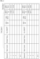
- Measurement and calculation of field data is performed in real time from the battery in operation in a predetermined time unit, and FIG. 1 illustrates an example of each field data measured and calculated in the present invention.
- the measurement and calculation of field data can be performed in each cell battery management system (BMS), module battery management system (BMS) or rack battery management system (BMS), and the field data is transmitted to the field data calculation unit 100.
- the field data calculation unit may be configured to be integrated into the rack BMS.
- field data obtained in a certain section or for a predetermined time are pre-processed and extracted as training data as shown in FIG. 2 .
- the field data pre-processing process for cell voltage prediction is a field data pre-processing process for cell voltage prediction of extracting data for cell voltage prediction from the calculated field data.
- a cell voltage is predicted using a cell voltage prediction model that predicts the cell voltage from field data.
- data for cell voltage prediction as shown in FIG. 2 , the rack current, ambient temperature, SOC, SOH, and cell voltage of the previous cycle are used as input values.
- FIG. 2 illustrates a data format for extracting Rack.Current(t), Ambient.Temp(t), Fan.ON(t), SOC.Mk(t) values for each time cycle and SOH_M1C2(t) and Cell_V_M1C2(t) values of cells 1 and 2 of module 1 corresponding to them.
- the field data pre-processing for cell temperature prediction is a process of extracting data for predicting the cell temperature from the calculated field data.
- a cell temperature is predicted using a cell temperature prediction model that predicts the cell temperature from field data.
- the cell temperature of the next cycle is predicted using Cell.T.MkCj(t), which is the current temperature value of the cell, ambient temperature Ambient.Temp(t), and Fan.ON(t).
- the Cell.T.MkCj(t), Ambient.Temp(t), and Fan.ON(t) values are periodically extracted from field data calculated in real time at a predetermined cycle.
- a cell voltage prediction model 210 for cell voltage prediction is generated by conducting supervised learning by inputting Rack.Current(t), Ambient.Temp(t), Fan.ON(t), SOC.Mk(t), SOH.MkCj(t), Cell.V.MkCj(t) to a predetermined artificial intelligence neural network and using the output value thereof as Cell. V.MkCj (t+ 1).
- the cell voltage prediction model is generated using a predetermined artificial intelligence neural network.
- a known artificial intelligence neural network can be used as the artificial intelligence neural network, and the artificial intelligence neural network that has been trained with predetermined training data is stored as the cell voltage prediction model 210 of FIG. 5 .
- the Rack.Current(t), Ambient.Temp(t), Fan.ON(t), SOC.Mk(t), SOH.MkCj(t), Cell.V.MkCj(t) values for a predetermined time section pre-processed through the field data pre-processing process (S120) for cell voltage prediction are used as input values to the neural network and Cell.V.MkCj(t+1), which is the cell voltage measurement value of the next cycle, is used as the output value thereof, and the cell voltage prediction model is generated by conducting supervised learning on the artificial intelligence neural network so that when the Rack.Current(t), Ambient.Temp(t), Fan.ON(t), SOC.Mk(t), SOH.MkCj(t), Cell.V.MkCj(t) values for a predetermined time section are input to the artificial intelligence neural network, the output value becomes Cell. V.MkCj (t+ 1), which is the cell voltage measurement value of the next cycle.
- the artificial intelligence neural network trained in this way is stored as the cell voltage prediction model 210, which receives the Rack.Current(t), Ambient.Temp(t), Fan.ON(t), SOC.Mk(t), SOH.MkCj(t), Cell.V.MkCj(t) values, and calculates Cell.V predic .MkCj(t+1), which is the cell voltage prediction value of the next cycle.
- the Rack.Current(t), Ambient.Temp(t), Fan.ON(t), SOC.Mk(t), SOH.MkCj(t), Cell.V.MkCj(t), Cell.V.MkCj( t+1) values which are the training data used in the cell voltage prediction model generation process, may be field data measured at a different time from data used in a cell voltage prediction process (S310) below, and may be sample data obtained before battery operation or through operation of sample batteries.
- the cell voltage prediction model may be generated by using Rack.Current(t), Ambient.Temp(t), Fan.ON(t), SOC.Mk(t), SOH.MkCj(t), Cell.V.MkCj(t), Cell.V.MkCj( t+1) for a predetermined time section as training data of the cell voltage prediction model 210, not field data.
- the cell voltage prediction model is generated by being trained using data corresponding values for predicting cell voltage calculated from a standard battery rather than a battery in operation for which the field data is calculated, as training data. Thereafter, the cell voltage prediction model receives data for predicting the cell voltage from the battery in operation and outputs a prediction value of the cell voltage of the next cycle.
- a cell temperature prediction model is also included.
- the cell temperature prediction model 220 for cell temperature prediction is also generated in the same manner as the cell voltage prediction model generation process, using the pre-processed data as training data. That is, supervised learning is conducted by periodically inputting Cell.T.MkCj(t), Ambient.Temp(t), Fan.ON(t) values to a predetermined artificial intelligence neural network, and using the output value thereof as Cell.T.MkCj(t+1).
- the cell temperature prediction model is generated by conducting supervised learning on the artificial intelligence neural network so that Cell.T.MkCj(t), Ambient.Temp(t), Fan.ON(t) values are periodically input for a predetermined time as input data of artificial intelligence neural network and the output value becomes Cell.T.MkCj(t+1), which is the cell temperature measurement value of the next cycle.
- the artificial intelligence neural network trained in this way is stored as the cell temperature prediction model 220, which receives the Cell.T.MkCj(t), Ambient.Temp(t), Fan.ON(t) values and calculates Cell.T predic .MkCj(t+1), which is the cell temperature prediction value of the next cycle.
- the Cell.T.MkCj(t), Ambient.Temp(t), Fan.ON(t), Cell.T.MkCj(t+ 1) values which are the training data used in the cell temperature prediction model generation process, may be field data measured at a different time from data used in the cell temperature prediction process (S320) below, and may be sample data obtained before battery operation or through operation of sample batteries.
- the cell temperature prediction model may be generated by using the Cell.T.MkCj(t), Ambient.Temp(t), Fan.ON(t), Cell.T.MkCj(t+ 1) values for a predetermined time section calculated using a standard battery in a laboratory as training data, not field data.
- the cell temperature prediction model 220 is generated by being trained using data corresponding values for predicting cell temperature calculated from the standard battery rather than a battery in operation for which the field data is calculated as training data, and receives data for predicting the cell temperature from the battery in operation and outputs a prediction value of the cell temperature of the next cycle.
- Another embodiment is a process of re-training and updating the cell voltage prediction model and the cell temperature prediction model by adding field data for a predetermined period of a normal operation section of the battery in operation, for which the field data is calculated, as new training data.
- the cell voltage prediction model 210 may be updated by inputting the Rack.Current(t), Ambient.Temp(t), Fan.ON(t), SOC.Mk(t), SOH.MkCj(t), Cell.V.MkCj(t), Cell.V.MkCj( t+1) values for a predetermined time calculated while the battery does not exhibit malfunctioning behavior as new training data.
- the training model since the training model is updated by applying actual field data, it is possible to obtain a more accurate prediction value for the actual battery disposed in the field.
- the cell temperature prediction model 220 may be updated by inputting Cell.T.MkCj(t), Ambient.Temp(t), Fan.ON(t), Cell.T.MkCj(t+ 1) values for a predetermined time calculated while the battery does not exhibit malfunctioning behavior as new learning data.
- the training model is updated by applying actual field data (S230), it is possible to obtain a more accurate prediction value for the actual battery disposed in the field.
- the real-time prediction process is a procedure for predicting cell voltage and cell temperature using the cell voltage prediction model and cell temperature prediction model for which the training has been completed.
- the cell voltage prediction process is a procedure for inputting Rack.Current(t), Ambient.Temp(t), Fan.ON(t), SOC.Mk(t), SOH.MkCj(t), Cell.V.MkCj(t) values pre-processed and extracted in the field data pre-processing process (S120) for cell voltage prediction to the generated or updated cell voltage prediction model 210 and calculating Cell.V predic .MkCj(t+1), which is a cell voltage prediction value of the next cycle.
- the Cell.T.MkCj(t), Ambient.Temp(t), Fan.ON(t) values extracted in the pre-processing process are input into the generated or updated cell temperature prediction model 220 and calculating Cell.T predic .MkCj(t+1), which is the cell temperature prediction value of the next cycle.
- This cell voltage malfunctioning behavior detection process is a process of detecting a case in which the Cell.V pedic .MkCj(t+1) value, which is a prediction value output by the cell voltage prediction model 210 through the cell voltage prediction process (S310), is compared with the Cell. V.MkCj (t+ 1) value of the field data calculated from the battery and a difference greater than or equal to a predetermined reference value occurs. When the difference greater than or equal to the predetermined reference value occurs, a cell voltage malfunctioning behavior detection signal is generated.
- This cell temperature malfunctioning behavior detection process is a process of detecting a case in which the Cell.T predic .MkCj(t+1) value, which is a prediction value output by the cell temperature prediction model 220 through the cell temperature prediction process (S320), is compared with the Cell.T.MkCj(t+ 1) value in field data calculated from the battery and a difference greater than or equal to a predetermined reference value occurs. When the difference greater than or equal to a predetermined reference value occurs, a cell temperature malfunctioning behavior detection signal is generated.
- the Cell.T.MkCj(t+ 1) values which are field data are indicated as 'test data' and the Cell.T predic .MkCj(t+1) which are prediction value are indicated as 'simulation'.
- the deviation greater than or equal to a predetermined reference value does not occur between the field data and the prediction value, it is determined as normal behavior
- the deviation greater than or equal to the predetermined reference value occurs between the field data and the prediction value, it is determined and detected as battery malfunctioning behavior.
- the diagnosis and alarm generation process is a procedure for performing a diagnosis procedure or generating an alarm externally when the difference between the Cell.V predic .MkCj(t+1) value, Cell.T predic .MkCj(t+1) values and the Cell.V.MkCj(t+1) value, Cell.T.MkCj(t+ 1) value, which is greater than or equal to a reference value, occurs.
- the diagnostic procedure is not limited to a specially defined procedure, and when the deviation greater than or equal to the reference value occurs more than a predetermined number of times during a predetermined time section, an alarm generation signal may be output or a control signal for blocking a battery charging or discharging operation may be output.
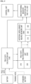
- the field data calculation unit 100 receives real-time measurement values from the battery in operation, calculates field data values from the received data, and outputs the calculated values. Measurement and calculation of field data may be performed in each cell battery management system (BMS), module battery management system (BMS), or rack battery management system (BMS), and the field data are transmitted to the field data calculation unit 100.
- the field data calculation unit may be configured to be integrated into the rack BMS.
- the measurement values received from the battery are values received from respective sensors installed in the battery, and include normal battery state information measurement values.
- the calculated field data are field data of the present invention described above.
- the field data calculation unit transmits the field data to the field data pre-processing unit 200.
- the field data pre-processing unit 200 is configured to include a cell voltage prediction field data pre-processing unit 210 that extracts field data for cell voltage prediction and a cell temperature prediction field data pre-processing unit 220 that extracts field data for cell temperature prediction, from the field data calculated by the field data calculation unit 210, and performs the field data pre-processing process for cell voltage prediction (S120) and the field data pre-processing process for cell temperature prediction (S130).
- the field data pre-processing unit 200 transmits training data and field data to the artificial intelligence neural network unit 300.
- the training data may be provided to the artificial intelligence neural network unit 300 by calculating data corresponding to each item constituting field data from a standard battery, of which normal quality has been verified in a laboratory, for a predetermined period of time. That is, the cell voltage prediction model 320 constituting the artificial intelligence neural network unit is trained using field data corresponding values for predicting cell voltage calculated from the standard battery as training data, and the cell temperature prediction model 330 may be trained using field data corresponding values for predicting cell temperature calculated from the standard battery as training data.
- a configuration in which the training data is provided to the artificial intelligence neural network unit 300 by extracting field data for a certain period of time as training data during battery operation may be adopted.
- the field data pre-processing unit 200 may provide the field data of the battery in the normal operation section as the training data so that the pre-trained artificial intelligence neural networks 320 and 330 are trained.
- Neural network training unit 310 (1) Neural network training unit 310
- the neural network training unit 310 receives the training data described above from the field data pre-processing unit 200 and trains the artificial intelligence neural network.
- the artificial intelligence neural network is trained as the cell voltage prediction model 320 and the cell temperature prediction model 330, and in the the neural network training unit, the prediction models are trained to predict cell voltage and cell temperature, respectively, and stored.
- the neural network training unit 310 can also be controlled to retrain the artificial intelligence neural network by adding field data for a predetermined period of the battery normal operation section as new training data at a predetermined cycle or under the control of the control unit 500 so as to update the prediction models 320 and 330.
- the prediction models 320 and 330 are trained and operated with the training data provided from the standard battery and generate prediction values by receiving field data, by re-training the prediction models 320 and 330 by adding field data in a section during which malfunctioning behavior is not detected by the battery malfunctioning behavior detection unit 400 described later, that is, in a normal section, to the training data, the prediction models 320 and 330 are trained to reflect field data generated from the operating state of the actual field battery, which improves the prediction accuracy of the prediction models 320 and 330.
- the artificial intelligence neural networks which have been trained with the training data or which have been re-trained and updated by adding field data is stored as the cell voltage prediction model 320 and the cell temperature prediction model 330, respectively.
- the cell voltage prediction model 320 is a trained artificial intelligence neural network that receives field data for cell voltage prediction from the field data pre-processing unit 200 and predicts cell voltage of the next cycle.
- the field data for cell voltage prediction may be Rack.Current(t), Ambient.Temp(t), Fan.ON(t), SOC.Mk(t), SOH.MkCj(t), Cell.V.MkCj(t) values, and Cell.V predic .MkCj(t+1), which is a cell voltage prediction value, is calculated by receiving these values.
- the cell temperature prediction model 330 is a trained artificial intelligence neural network that receives field data for cell temperature prediction from the field data pre-processing unit 200 and predicts the cell temperature of the next cycle.
- the field data for cell temperature prediction may be Cell.T.MkCj(t), Ambient.Temp(t), Fan.ON(t) values, and Cell.T predic .MkCj(t+1), which is a cell temperature prediction value, is calculated by receiving these values.
- the battery malfunctioning behavior detection unit 400 compares prediction values of cell voltage and cell temperature calculated by the cell voltage prediction model 320 and the cell temperature prediction model 330 of the artificial intelligence neural network unit 300 with cell voltage and cell temperature of field data, detects malfunctioning behavior of the battery, and transmits a malfunctioning behavior detection signal to a control unit.
- the malfunctioning behavior detection signal may include at least one or both of a cell voltage malfunctioning behavior signal and a cell temperature malfunctioning behavior signal, which will be described later.
- the battery malfunctioning behavior detection unit 400 receives field data output by the field data calculation unit and the prediction value output by the artificial intelligence neural network unit 300.
- the cell voltage malfunctioning behavior determination unit 410 compares the Cell.V predic .MkCj(t+1) value described above with the Cell.V.MkCj(t+1) value of the field data, and determines that it is the cell voltage malfunctioning behavior when the deviation is greater than or equal to a predetermined range, and transmits the cell voltage malfunctioning behavior signal to the control unit.
- the cell temperature malfunctioning behavior determination unit 420 compares the Cell.T predic .MkCj(t+1) value described above with the Cell.T.MkCj(t+1) value of the field data, determines that it is the cell temperature malfunctioning behavior when the deviation is greater than or equal to the predetermined range, and transmits the cell temperature malfunctioning behavior signal to the control unit.
- Control unit 500 Control unit 500
- the control unit 500 receives the malfunctioning behavior detection signal from the malfunctioning behavior detection unit 400 and performs the diagnosis and alarm generation process (S500) described above.
- the control unit may be respectively connected to the field data calculation unit, the field data pre-processing unit, the prediction model, and the malfunctioning behavior detection unit to control respective configurations.
- all configurations of the field data calculation unit, the field data pre-processing unit, the prediction model, and the malfunctioning behavior detection unit may be physically integrated to be configured as the control unit.
- the integrated control unit may be implemented by being directly connected to the rack BMS of the battery or integrated into the rack BMS.
Landscapes
- Physics & Mathematics (AREA)
- General Physics & Mathematics (AREA)
- Engineering & Computer Science (AREA)
- Theoretical Computer Science (AREA)
- Power Engineering (AREA)
- Data Mining & Analysis (AREA)
- General Health & Medical Sciences (AREA)
- Biomedical Technology (AREA)
- Biophysics (AREA)
- Computational Linguistics (AREA)
- Life Sciences & Earth Sciences (AREA)
- Evolutionary Computation (AREA)
- Artificial Intelligence (AREA)
- Molecular Biology (AREA)
- Computing Systems (AREA)
- General Engineering & Computer Science (AREA)
- Mathematical Physics (AREA)
- Software Systems (AREA)
- Health & Medical Sciences (AREA)
- Secondary Cells (AREA)
- Tests Of Electric Status Of Batteries (AREA)
Abstract
Description
- The present invention relates to a battery malfunction detection method and system through a battery model. In particular, the present invention relates to a method and system for detecting battery malfunction through an artificial intelligence neural network battery model using field data rather than a conventional chemical/electrical equivalent circuit model in constructing the battery model.
- Conventionally, general Li-ion battery modeling was implemented using the chemical composition or electrical equivalent circuit. In the case of the corresponding battery modeling, modeling is basically performed based on cell test data including charging/discharging.
- However, the internal cell test data is different from that of the actual field environment. In addition, even if an internal cell test is performed under various conditions, it may not be possible to secure sufficient data due to limitations in realistic experiments such as the number of cell samples, module/rack unit, degree of deterioration, temperature conditions, test equipment, and time.
- In this regard,
patent document 1 proposes a system for receiving measured initial characteristic data of a battery, training an artificial intelligence neural network, predicting long-term characteristic data therefrom, and determining the reliability thereof, andpatent document 2 discloses a battery state estimation method in which physical quantity information of a battery is input to a battery training model and estimation information is obtained from the battery training model. - By the way, these conventional technologies are still insufficient to implement a method of estimating the state of the battery based on actual field data and determining whether or not the battery is malfunctioning.
- Related prior art includes the following documents.
- Patent Document 1:
Korean Laid-open Patent Publication No. 10-2009-0020448 - Patent Document 2:
Korean Laid-open Patent Publication No. 10-2018-0057226 - In order to solve the problems described above, the present invention is to provide a method and system for detecting malfunction of a battery cell by utilizing field data.
- There is also a problem to be solved in utilizing the field data, which is that there are inevitably limitations on types of data collection items and the accuracy thereof is low.
- In order to solve this problem, it is intended to provide a battery malfunction detection method and system in which a battery modeling through AI training is implemented in order to model a battery by utilizing various field data and which uses the battery modeling.
- In order to solve the problems described above, according to the present invention, there is provided, as a system for detecting malfunctioning behavior of a battery, a battery malfunctioning behavior detection system configured to include a field data calculation unit that receives real-time measurement values from a battery in operation and calculates and outputs field data from the real-time measurement values, a field data pre-processing unit that extracts and outputs field data for predicting a cell voltage from the field data, an artificial intelligence neural network unit that receives an output of the field data pre-processing unit to predict the cell voltage and outputs a prediction value of the cell voltage, and a battery malfunctioning behavior detection unit that compares the prediction value output by the artificial intelligence neural network unit with the field data and determines that it is malfunctioning behavior when the deviation is greater than or equal to a predetermined range.
- The artificial intelligence neural network unit may be configured to include a cell voltage prediction model that is trained using field data corresponding values for predicting the cell voltage calculated from a standard battery rather than a battery for which the field data is calculated, as training data, receives the field data for predicting the cell voltage, and outputs the prediction value of the cell voltage of the next cycle, a cell temperature prediction model that is trained using field data corresponding values for predicting the cell temperature calculated from the standard battery rather than the battery for which the field data is calculated, as training data, receives the field data for predicting the cell temperature, and outputs the prediction value of the cell temperature of the next cycle, and may further include a neural network training unit that re-trains and updates the cell voltage prediction model and the cell temperature prediction model by adding field data for a predetermined period of a normal operation section of the battery as new training data.
- According to the present invention, there is also provided a battery malfunctioning behavior detection method configured to include a field data calculation process of measuring and calculating real-time battery state information data from a battery in operation, a field data pre-processing process including a field data pre-processing process for cell voltage prediction of extracting data for cell voltage prediction from calculated field data, a real-time prediction process including a cell voltage prediction process of inputting the data for cell voltage prediction into a cell voltage prediction model and calculating a cell voltage prediction value of the next cycle, and a battery malfunctioning behavior detection process including a cell voltage malfunctioning behavior detection process of comparing the cell voltage prediction value with a cell voltage value of the field data and generating a cell voltage malfunctioning behavior detection signal when the deviation is greater than or equal to a predetermined range.
- In this case, the data for predicting the cell voltage may be time-series values of rack current, ambient temperature, fan on-off information, module SOC, cell SOH, and cell voltage for each battery cell and battery module constituting the battery, and the data for predicting the cell temperature may be time series values of cell temperature, ambient temperature, and fan on/off information for each battery cell and battery module constituting the battery.
- According to the present invention, it is possible to predict battery temperature value and voltage value in real time using battery field data and compare the predicted battery temperature value and voltage value with actual temperature value and voltage value to detect in real-time whether or not the battery operates abnormally.
- The following drawings attached to this specification are intended to illustrate a preferred embodiment of the present invention, and serve to make further understand the technical idea of the present invention together with the detailed description of the invention described above, and thus the present invention should not be construed as being limited only to the matters described in the drawings.
-
FIG. 1 is a diagram illustrating an example of respective pieces of field data measured and calculated in the present invention. -
FIG. 2 is a diagram illustrating an example of extracting training data by pre-processing field data acquired during a certain section or for a predetermined time, from among the field data ofFIG. 1 . -
FIG. 3 is a diagram illustrating a sequence of a battery malfunctioning behavior detection method according to the present invention. -
FIG. 4 illustrates a graph illustrating field data values of cell temperature and prediction values of cell temperature over time. -
FIG. 5 is a block diagram of a battery malfunctioning behavior detection system according to the present invention. - The present invention trains prediction model using field data to predict voltage and temperature at a next time point. Types of field data used in the present invention are as follows.
- In the present invention, 'field data' means the following data measured in real time from a battery in operation and the following data calculated therefrom. The field data are time-series data of battery state information calculated during battery operation at predetermined time intervals.
- The types of field data used in the present invention are as follows.
- The rack data is data of a battery rack. The rack data includes rack current, ambient temperature, and fan on/off information. These are usually measured and calculated by a rack battery management system (BMS).
- The rack current can be expressed as Rack.Current, ambient temperature as Ambient. Temp, and fan on/off information as Fan_ON/OFF flag value, and they are measured at predetermined time intervals.
- The values of the rack current, ambient (Ambient Temp.), and Fan.ON values of Fan ON/OFF information at time t measured at a predetermined cycle can be expressed as Rack.Current(t), Ambient.Temp(t), Fan.ON(t). In this case, the values of Rack.Current(t) and Ambient.Temp(t) have measured values of appropriate measurement sensors, and Fan.ON(t) can have a value of '1' when the fan is running and '0' when the fan is not running.
- For example, when measured at 1-second intervals, the rack current, ambient temperature, and fan on/off information (if the fan is running) at 3 seconds after driving can be respectively expressed as Rack.Current(3), Ambient.Temp(3), and Fan.ON(3).
- The module data is data of each of a plurality of battery modules included in the battery rack. The module data includes an SOC value of each module, and when there are i modules constituting the battery rack, each module is expressed as Mk (k = 1, 2, 3, ...i), and the SOC value of each module (SOC M) is expressed as SOC.Mk. For example, the SOC value of the second module is expressed as SOC.M2. The module data is usually measured and calculated by a module battery management system (BMS).
- Like the rack data, the SOC.Mk value can be measured at predetermined time intervals, and the SOC.Mk value at time t is denoted as SOC.Mk(t).
- The cell data is data of each of a plurality of battery cells included in the battery module. The cell data includes a cell voltage value Cell V as a voltage measurement value of each cell, and the cell voltage value is denoted as Cell.V.MkCj (j = 1, 2, 3, ...m), whereas each module is composed of m cells. For example, the cell voltage value of the third cell of the second module is denoted as Cell_V_M2C3. The cell data is usually measured and calculated by a cell battery management system (BMS) or, a module battery management system (BMS) when there is no cell BMS.
- The Cell.V.MkCj value can also be measured at predetermined time intervals, and the Cell.V.MkCj value at time t is denoted as Cell.V.MkCj(t).
- The cell data may include cell temperature. The cell temperature of j-th cell of the k-th module at time t is denoted as Cell.T.MkCj(t).
- The present invention also uses an SOH value SOH MkCj as one of the calculated values. The SOH value of each cell is calculated by the cell battery management system (BMS), the module battery management system (BMS) or the rack battery management system (BMS), and the SOH of a specific cell is denoted as SOH.MkCj (k = 1, 2, 3, ...m).
- The SOH.MkCj value can also be measured at predetermined time intervals, and the SOH.MkCj value at time t is denoted as SOH.MkCj(t).
- The battery malfunctioning behavior detection method according to the present invention will be described with reference to
FIG. 3 . - This process is a procedure for measuring, calculating, and pre-processing the field data described above.
- The field data calculation process is a process of measuring and calculating battery state information data in real-time from a battery in operation.
- Measurement and calculation of field data is performed in real time from the battery in operation in a predetermined time unit, and
FIG. 1 illustrates an example of each field data measured and calculated in the present invention. - The measurement and calculation of field data can be performed in each cell battery management system (BMS), module battery management system (BMS) or rack battery management system (BMS), and the field data is transmitted to the field
data calculation unit 100. The field data calculation unit may be configured to be integrated into the rack BMS. - Among the field data shown in
FIG. 1 and described above, field data obtained in a certain section or for a predetermined time are pre-processed and extracted as training data as shown inFIG. 2 . - The field data pre-processing process for cell voltage prediction is a field data pre-processing process for cell voltage prediction of extracting data for cell voltage prediction from the calculated field data.
- In the present invention, a cell voltage is predicted using a cell voltage prediction model that predicts the cell voltage from field data. As data for cell voltage prediction, as shown in
FIG. 2 , the rack current, ambient temperature, SOC, SOH, and cell voltage of the previous cycle are used as input values. - To this end, in the pre-processing process, Rack.Current(t), Ambient.Temp(t), Fan.ON(t), SOC.Mk(t), SOH.MkCj(t), and Cell.V.MkCj(t) values, which are rack current, ambient temperature, SOC, SOH, cell voltage values, are periodically extracted from the field data calculated in real time at a predetermined cycle.
FIG. 2 illustrates a data format for extracting Rack.Current(t), Ambient.Temp(t), Fan.ON(t), SOC.Mk(t) values for each time cycle and SOH_M1C2(t) and Cell_V_M1C2(t) values ofcells module 1 corresponding to them. - The field data pre-processing for cell temperature prediction is a process of extracting data for predicting the cell temperature from the calculated field data.
- In the present invention, a cell temperature is predicted using a cell temperature prediction model that predicts the cell temperature from field data. As data for cell temperature prediction, the cell temperature of the next cycle is predicted using Cell.T.MkCj(t), which is the current temperature value of the cell, ambient temperature Ambient.Temp(t), and Fan.ON(t).
- To this end, in the pre-processing process, the Cell.T.MkCj(t), Ambient.Temp(t), and Fan.ON(t) values are periodically extracted from field data calculated in real time at a predetermined cycle.
- A cell
voltage prediction model 210 for cell voltage prediction is generated by conducting supervised learning by inputting Rack.Current(t), Ambient.Temp(t), Fan.ON(t), SOC.Mk(t), SOH.MkCj(t), Cell.V.MkCj(t) to a predetermined artificial intelligence neural network and using the output value thereof as Cell. V.MkCj (t+ 1). The cell voltage prediction model is generated using a predetermined artificial intelligence neural network. A known artificial intelligence neural network can be used as the artificial intelligence neural network, and the artificial intelligence neural network that has been trained with predetermined training data is stored as the cellvoltage prediction model 210 ofFIG. 5 . - As the training data of the cell
voltage prediction model 210, the Rack.Current(t), Ambient.Temp(t), Fan.ON(t), SOC.Mk(t), SOH.MkCj(t), Cell.V.MkCj(t) values for a predetermined time section pre-processed through the field data pre-processing process (S120) for cell voltage prediction are used as input values to the neural network and Cell.V.MkCj(t+1), which is the cell voltage measurement value of the next cycle, is used as the output value thereof, and the cell voltage prediction model is generated by conducting supervised learning on the artificial intelligence neural network so that when the Rack.Current(t), Ambient.Temp(t), Fan.ON(t), SOC.Mk(t), SOH.MkCj(t), Cell.V.MkCj(t) values for a predetermined time section are input to the artificial intelligence neural network, the output value becomes Cell. V.MkCj (t+ 1), which is the cell voltage measurement value of the next cycle. - The artificial intelligence neural network trained in this way is stored as the cell
voltage prediction model 210, which receives the Rack.Current(t), Ambient.Temp(t), Fan.ON(t), SOC.Mk(t), SOH.MkCj(t), Cell.V.MkCj(t) values, and calculates Cell.Vpredic.MkCj(t+1), which is the cell voltage prediction value of the next cycle. - The Rack.Current(t), Ambient.Temp(t), Fan.ON(t), SOC.Mk(t), SOH.MkCj(t), Cell.V.MkCj(t), Cell.V.MkCj( t+1) values, which are the training data used in the cell voltage prediction model generation process, may be field data measured at a different time from data used in a cell voltage prediction process (S310) below, and may be sample data obtained before battery operation or through operation of sample batteries.
- In another embodiment, the cell voltage prediction model may be generated by using Rack.Current(t), Ambient.Temp(t), Fan.ON(t), SOC.Mk(t), SOH.MkCj(t), Cell.V.MkCj(t), Cell.V.MkCj( t+1) for a predetermined time section as training data of the cell
voltage prediction model 210, not field data. - That is, the cell voltage prediction model is generated by being trained using data corresponding values for predicting cell voltage calculated from a standard battery rather than a battery in operation for which the field data is calculated, as training data. Thereafter, the cell voltage prediction model receives data for predicting the cell voltage from the battery in operation and outputs a prediction value of the cell voltage of the next cycle.
- In the present invention, a cell temperature prediction model is also included. The cell
temperature prediction model 220 for cell temperature prediction is also generated in the same manner as the cell voltage prediction model generation process, using the pre-processed data as training data. That is, supervised learning is conducted by periodically inputting Cell.T.MkCj(t), Ambient.Temp(t), Fan.ON(t) values to a predetermined artificial intelligence neural network, and using the output value thereof as Cell.T.MkCj(t+1). The cell temperature prediction model is generated by conducting supervised learning on the artificial intelligence neural network so that Cell.T.MkCj(t), Ambient.Temp(t), Fan.ON(t) values are periodically input for a predetermined time as input data of artificial intelligence neural network and the output value becomes Cell.T.MkCj(t+1), which is the cell temperature measurement value of the next cycle. - The artificial intelligence neural network trained in this way is stored as the cell
temperature prediction model 220, which receives the Cell.T.MkCj(t), Ambient.Temp(t), Fan.ON(t) values and calculates Cell.Tpredic.MkCj(t+1), which is the cell temperature prediction value of the next cycle. - The Cell.T.MkCj(t), Ambient.Temp(t), Fan.ON(t), Cell.T.MkCj(t+ 1) values, which are the training data used in the cell temperature prediction model generation process, may be field data measured at a different time from data used in the cell temperature prediction process (S320) below, and may be sample data obtained before battery operation or through operation of sample batteries.
- In another embodiment, the cell temperature prediction model may be generated by using the Cell.T.MkCj(t), Ambient.Temp(t), Fan.ON(t), Cell.T.MkCj(t+ 1) values for a predetermined time section calculated using a standard battery in a laboratory as training data, not field data.
- That is, the cell
temperature prediction model 220 is generated by being trained using data corresponding values for predicting cell temperature calculated from the standard battery rather than a battery in operation for which the field data is calculated as training data, and receives data for predicting the cell temperature from the battery in operation and outputs a prediction value of the cell temperature of the next cycle. - Another embodiment is a process of re-training and updating the cell voltage prediction model and the cell temperature prediction model by adding field data for a predetermined period of a normal operation section of the battery in operation, for which the field data is calculated, as new training data.
- In the cell voltage prediction model generation process, the cell
voltage prediction model 210 may be updated by inputting the Rack.Current(t), Ambient.Temp(t), Fan.ON(t), SOC.Mk(t), SOH.MkCj(t), Cell.V.MkCj(t), Cell.V.MkCj( t+1) values for a predetermined time calculated while the battery does not exhibit malfunctioning behavior as new training data. In this case, since the training model is updated by applying actual field data, it is possible to obtain a more accurate prediction value for the actual battery disposed in the field. - In the cell temperature prediction model generation process, the cell
temperature prediction model 220 may be updated by inputting Cell.T.MkCj(t), Ambient.Temp(t), Fan.ON(t), Cell.T.MkCj(t+ 1) values for a predetermined time calculated while the battery does not exhibit malfunctioning behavior as new learning data. In this case, since the training model is updated by applying actual field data (S230), it is possible to obtain a more accurate prediction value for the actual battery disposed in the field. - The real-time prediction process is a procedure for predicting cell voltage and cell temperature using the cell voltage prediction model and cell temperature prediction model for which the training has been completed.
- The cell voltage prediction process is a procedure for inputting Rack.Current(t), Ambient.Temp(t), Fan.ON(t), SOC.Mk(t), SOH.MkCj(t), Cell.V.MkCj(t) values pre-processed and extracted in the field data pre-processing process (S120) for cell voltage prediction to the generated or updated cell
voltage prediction model 210 and calculating Cell.Vpredic.MkCj(t+1), which is a cell voltage prediction value of the next cycle. - In the cell temperature prediction process, the Cell.T.MkCj(t), Ambient.Temp(t), Fan.ON(t) values extracted in the pre-processing process (S220) are input into the generated or updated cell
temperature prediction model 220 and calculating Cell.Tpredic.MkCj(t+1), which is the cell temperature prediction value of the next cycle. - This cell voltage malfunctioning behavior detection process is a process of detecting a case in which the Cell.Vpedic.MkCj(t+1) value, which is a prediction value output by the cell
voltage prediction model 210 through the cell voltage prediction process (S310), is compared with the Cell. V.MkCj (t+ 1) value of the field data calculated from the battery and a difference greater than or equal to a predetermined reference value occurs. When the difference greater than or equal to the predetermined reference value occurs, a cell voltage malfunctioning behavior detection signal is generated. - This cell temperature malfunctioning behavior detection process is a process of detecting a case in which the Cell.Tpredic.MkCj(t+1) value, which is a prediction value output by the cell
temperature prediction model 220 through the cell temperature prediction process (S320), is compared with the Cell.T.MkCj(t+ 1) value in field data calculated from the battery and a difference greater than or equal to a predetermined reference value occurs. When the difference greater than or equal to a predetermined reference value occurs, a cell temperature malfunctioning behavior detection signal is generated. - When describing an example of the detection with reference to
FIG. 4 , the Cell.T.MkCj(t+ 1) values which are field data are indicated as 'test data' and the Cell.Tpredic.MkCj(t+1) which are prediction value are indicated as 'simulation'. As illustrated in (a) ofFIG. 4 , when the deviation greater than or equal to a predetermined reference value does not occur between the field data and the prediction value, it is determined as normal behavior, and, as illustrated in (b) ofFIG. 4 , when the deviation greater than or equal to the predetermined reference value occurs between the field data and the prediction value, it is determined and detected as battery malfunctioning behavior. - The diagnosis and alarm generation process is a procedure for performing a diagnosis procedure or generating an alarm externally when the difference between the Cell.Vpredic.MkCj(t+1) value, Cell.Tpredic.MkCj(t+1) values and the Cell.V.MkCj(t+1) value, Cell.T.MkCj(t+ 1) value, which is greater than or equal to a reference value, occurs.
- In the present invention, the diagnostic procedure is not limited to a specially defined procedure, and when the deviation greater than or equal to the reference value occurs more than a predetermined number of times during a predetermined time section, an alarm generation signal may be output or a control signal for blocking a battery charging or discharging operation may be output.
- Referring to
FIG. 5 , a battery malfunctioning behavior detection system according to the present invention will be described. - The field
data calculation unit 100 receives real-time measurement values from the battery in operation, calculates field data values from the received data, and outputs the calculated values. Measurement and calculation of field data may be performed in each cell battery management system (BMS), module battery management system (BMS), or rack battery management system (BMS), and the field data are transmitted to the fielddata calculation unit 100. The field data calculation unit may be configured to be integrated into the rack BMS. The measurement values received from the battery are values received from respective sensors installed in the battery, and include normal battery state information measurement values. The calculated field data are field data of the present invention described above. - The field data calculation unit transmits the field data to the field
data pre-processing unit 200. - The field
data pre-processing unit 200 is configured to include a cell voltage prediction fielddata pre-processing unit 210 that extracts field data for cell voltage prediction and a cell temperature prediction fielddata pre-processing unit 220 that extracts field data for cell temperature prediction, from the field data calculated by the fielddata calculation unit 210, and performs the field data pre-processing process for cell voltage prediction (S120) and the field data pre-processing process for cell temperature prediction (S130). - The field
data pre-processing unit 200 transmits training data and field data to the artificial intelligenceneural network unit 300. - In this case, the training data, as indicated by the path of the arrow shown by the dotted line in
FIG. 5 , may be provided to the artificial intelligenceneural network unit 300 by calculating data corresponding to each item constituting field data from a standard battery, of which normal quality has been verified in a laboratory, for a predetermined period of time. That is, the cellvoltage prediction model 320 constituting the artificial intelligence neural network unit is trained using field data corresponding values for predicting cell voltage calculated from the standard battery as training data, and the celltemperature prediction model 330 may be trained using field data corresponding values for predicting cell temperature calculated from the standard battery as training data. - In another embodiment, a configuration in which the training data is provided to the artificial intelligence
neural network unit 300 by extracting field data for a certain period of time as training data during battery operation may be adopted. - Meanwhile, regardless of which of the two types of data is used as training data, the field
data pre-processing unit 200 may provide the field data of the battery in the normal operation section as the training data so that the pre-trained artificial intelligenceneural networks - The neural
network training unit 310 receives the training data described above from the fielddata pre-processing unit 200 and trains the artificial intelligence neural network. The artificial intelligence neural network is trained as the cellvoltage prediction model 320 and the celltemperature prediction model 330, and in the the neural network training unit, the prediction models are trained to predict cell voltage and cell temperature, respectively, and stored. - The neural
network training unit 310 can also be controlled to retrain the artificial intelligence neural network by adding field data for a predetermined period of the battery normal operation section as new training data at a predetermined cycle or under the control of thecontrol unit 500 so as to update theprediction models - For example, while the
prediction models prediction models behavior detection unit 400 described later, that is, in a normal section, to the training data, theprediction models prediction models - The artificial intelligence neural networks which have been trained with the training data or which have been re-trained and updated by adding field data is stored as the cell
voltage prediction model 320 and the celltemperature prediction model 330, respectively. - The cell
voltage prediction model 320 is a trained artificial intelligence neural network that receives field data for cell voltage prediction from the fielddata pre-processing unit 200 and predicts cell voltage of the next cycle. The field data for cell voltage prediction may be Rack.Current(t), Ambient.Temp(t), Fan.ON(t), SOC.Mk(t), SOH.MkCj(t), Cell.V.MkCj(t) values, and Cell.Vpredic.MkCj(t+1), which is a cell voltage prediction value, is calculated by receiving these values. - The cell
temperature prediction model 330 is a trained artificial intelligence neural network that receives field data for cell temperature prediction from the fielddata pre-processing unit 200 and predicts the cell temperature of the next cycle. The field data for cell temperature prediction may be Cell.T.MkCj(t), Ambient.Temp(t), Fan.ON(t) values, and Cell.Tpredic.MkCj(t+1), which is a cell temperature prediction value, is calculated by receiving these values. - The battery malfunctioning
behavior detection unit 400 compares prediction values of cell voltage and cell temperature calculated by the cellvoltage prediction model 320 and the celltemperature prediction model 330 of the artificial intelligenceneural network unit 300 with cell voltage and cell temperature of field data, detects malfunctioning behavior of the battery, and transmits a malfunctioning behavior detection signal to a control unit. The malfunctioning behavior detection signal may include at least one or both of a cell voltage malfunctioning behavior signal and a cell temperature malfunctioning behavior signal, which will be described later. - The battery malfunctioning
behavior detection unit 400 receives field data output by the field data calculation unit and the prediction value output by the artificial intelligenceneural network unit 300. - The cell voltage malfunctioning behavior determination unit 410 compares the Cell.Vpredic.MkCj(t+1) value described above with the Cell.V.MkCj(t+1) value of the field data, and determines that it is the cell voltage malfunctioning behavior when the deviation is greater than or equal to a predetermined range, and transmits the cell voltage malfunctioning behavior signal to the control unit.
- The cell temperature malfunctioning behavior determination unit 420 compares the Cell.Tpredic.MkCj(t+1) value described above with the Cell.T.MkCj(t+1) value of the field data, determines that it is the cell temperature malfunctioning behavior when the deviation is greater than or equal to the predetermined range, and transmits the cell temperature malfunctioning behavior signal to the control unit.
- The
control unit 500 receives the malfunctioning behavior detection signal from the malfunctioningbehavior detection unit 400 and performs the diagnosis and alarm generation process (S500) described above. - The control unit may be respectively connected to the field data calculation unit, the field data pre-processing unit, the prediction model, and the malfunctioning behavior detection unit to control respective configurations. In another embodiment, all configurations of the field data calculation unit, the field data pre-processing unit, the prediction model, and the malfunctioning behavior detection unit may be physically integrated to be configured as the control unit. In this case, the integrated control unit may be implemented by being directly connected to the rack BMS of the battery or integrated into the rack BMS.
Claims (11)
- A battery malfunctioning behavior detection system comprising:a field data calculation unit that receives real-time measurement values from a battery in operation and calculates and outputs field data from the real-time measurement values;a field data pre-processing unit that extracts and outputs field data for predicting a cell voltage from the field data;an artificial intelligence neural network unit that receives an output of the field data pre-processing unit to predict the cell voltage and outputs a prediction value of the cell voltage; anda battery malfunctioning behavior detection unit that compares the prediction value output by the artificial intelligence neural network unit with the field data and determines that it is malfunctioning behavior when the deviation is greater than or equal to a predetermined range.
- The system of claim 1, whereinthe field data pre-processing unitadditionally extracts and outputs field data for predicting cell temperature, the artificial intelligence neural network unitreceives the output of the field data pre-processing unit, additionally predicts the cell temperature, and outputs a prediction value of the cell temperature, andthe battery malfunctioning behavior detection unit
determines that it is battery malfunctioning behavior when the cell voltage prediction value output by the artificial intelligence neural network unit is compared with the cell voltage value of the field data and the deviation between the predicted cell voltage value and the cell voltage value is greater than or equal to a predetermined range, or when the cell temperature prediction value output by the artificial intelligence neural network unit is compared with the cell temperature value of the field data and the deviation between the predicted cell temperature value and the cell temperature value is greater than or equal to a predetermined range. - The system of claim 2, whereinthe field data for predicting the cell voltage
are time-series values of rack current, ambient temperature, fan on-off information, module SOC, cell SOH, and cell voltage for each battery cell and battery module constituting the battery, andthe field data for predicting the cell temperature
are time series values of cell temperature, ambient temperature, and fan on/off information for each battery cell and battery module constituting the battery. - The system of claim 3, wherein
the artificial intelligence neural network unitreceives the field data for predicting the cell voltage and outputs a prediction value of a cell voltage of the next cycle, andreceives the field data for predicting the cell temperature and outputs a prediction value of a cell temperature of the next cycle. - The system of claim 4, wherein
the artificial intelligence neural network unit is configured to comprisea cell voltage prediction model that is trained using field data corresponding values for predicting the cell voltage calculated from a standard battery rather than a battery for which the field data is calculated, as training data, receives the field data for predicting the cell voltage, and outputs the prediction value of the cell voltage of the next cycle, anda cell temperature prediction model that is trained using field data corresponding values for predicting the cell temperature calculated from the standard battery rather than the battery for which the field data is calculated, as training data, receives the field data for predicting the cell voltage and outputs the prediction value of the cell voltage of the next cycle. - The system of claim 5, wherein
the artificial intelligence neural network unit
further comprises a neural network training unit that re-trains and updates the cell voltage prediction model and the cell temperature prediction model by adding field data for a predetermined period of a normal operation section of the battery as new training data. - A battery malfunctioning behavior detection method comprising:a field data calculation process of measuring and calculating real-time battery state information data from a battery in operation;a field data pre-processing process including a field data pre-processing process for cell voltage prediction of extracting data for cell voltage prediction from calculated field data;a real-time prediction process including a cell voltage prediction process of inputting the data for cell voltage prediction into a cell voltage prediction model and calculating a cell voltage prediction value of the next cycle; anda battery malfunctioning behavior detection process including a cell voltage malfunctioning behavior detection process of comparing the cell voltage prediction value with a cell voltage value of the field data and generating a cell voltage malfunctioning behavior detection signal when the deviation is greater than or equal to a predetermined range.
- The method of claim 7, whereinthe field data pre-processing process
further comprises a field data pre-processing process for cell temperature prediction of extracting data for predicting cell temperature from the calculated field data,the real-time prediction process
further comprises a cell temperature prediction process of inputting data for cell temperature prediction into a cell temperature prediction model and calculating a cell temperature prediction value of the next cycle, andthe battery malfunctioning behavior detection process
further comprises a cell temperature malfunctioning behavior detection process of comparing the cell temperature prediction value with the cell temperature value of the field data and generating a cell temperature malfunctioning behavior detection signal when the deviation between the cell temperature prediction value and the cell temperature value is greater than or equal to a predetermined range. - The method of claim 8, whereinthe data for predicting the cell voltage
are time-series values of rack current, ambient temperature, fan on-off information, module SOC, cell SOH, and cell voltage for each battery cell and battery module constituting the battery, andthe data for predicting the cell temperature
are time series values of cell temperature, ambient temperature, and fan on/off information for each battery cell and battery module constituting the battery. - The method of claim 9, whereinthe cell voltage prediction model
is trained using data corresponding values for predicting the cell voltage calculated from a standard battery rather than a battery in operation for which the field data is calculated, as training data, receives the data for predicting the cell voltage from the battery in operation, and outputs the prediction value of the cell voltage of the next cycle, andthe cell temperature prediction model
is trained using data corresponding values for predicting the cell temperature calculated from a standard battery rather than the battery in operation for which the field data is calculated, as training data, and receives the data for predicting the cell temperature, and outputs the prediction value of the cell temperature of the next cycle. - The method of claim 10, further comprising:a prediction model update process of re-training and updating the cell voltage prediction model and the cell temperature prediction model by adding field data for a predetermined period of a normal operation section of the battery in operation that calculates the field data as new training data,wherein, in the real-time prediction process,
the data for cell voltage and cell temperature prediction are input to the cell voltage prediction model and the cell temperature prediction model updated through the prediction model update process to calculate the cell voltage prediction value and cell temperature prediction value of the next cycle.
Applications Claiming Priority (2)
| Application Number | Priority Date | Filing Date | Title |
|---|---|---|---|
| KR1020220039370A KR20230140743A (en) | 2022-03-30 | 2022-03-30 | Battery malfunction detection method and system through artificial intelligence neural network battery model based on field data |
| PCT/KR2023/001295 WO2023191283A1 (en) | 2022-03-30 | 2023-01-27 | Method and system for battery abnormality detection through artificial neural network battery model based on field data |
Publications (2)
| Publication Number | Publication Date |
|---|---|
| EP4400854A1 true EP4400854A1 (en) | 2024-07-17 |
| EP4400854A4 EP4400854A4 (en) | 2025-03-05 |
Family
ID=88203036
Family Applications (1)
| Application Number | Title | Priority Date | Filing Date |
|---|---|---|---|
| EP23781143.5A Pending EP4400854A4 (en) | 2022-03-30 | 2023-01-27 | METHOD AND SYSTEM FOR DETECTING BATTERY ABNORMALITY BY MEANS OF ARTIFICIAL NEURAL NETWORK BATTERY MODEL BASED ON FIELD DATA |
Country Status (7)
| Country | Link |
|---|---|
| US (1) | US20240393400A1 (en) |
| EP (1) | EP4400854A4 (en) |
| JP (1) | JP7771385B2 (en) |
| KR (1) | KR20230140743A (en) |
| CN (1) | CN118176427A (en) |
| AU (2) | AU2023246287A1 (en) |
| WO (1) | WO2023191283A1 (en) |
Family Cites Families (17)
| Publication number | Priority date | Publication date | Assignee | Title |
|---|---|---|---|---|
| KR100425352B1 (en) * | 1998-05-28 | 2004-03-31 | 도요다 지도샤 가부시끼가이샤 | Apparatus for estimating charged state of battery and method for estimating degraded state of battery |
| KR100793616B1 (en) * | 2005-06-13 | 2008-01-10 | 주식회사 엘지화학 | Apparatus and method for testing state of charge in battery |
| KR100936892B1 (en) | 2007-09-13 | 2010-01-14 | 주식회사 엘지화학 | Battery long-term prediction system and method |
| KR102424528B1 (en) * | 2015-06-11 | 2022-07-25 | 삼성전자주식회사 | Method and device to estimate state of battery |
| KR20170078387A (en) * | 2015-12-29 | 2017-07-07 | 삼성전자주식회사 | Method and apparatus for managing sensors |
| EA201990062A1 (en) * | 2016-07-22 | 2019-07-31 | Эос Энерджи Сторадж, Ллс | BATTERY MANAGEMENT SYSTEM |
| KR101914221B1 (en) | 2016-11-22 | 2018-11-05 | 김대영 | Mosquito net Holder of bed frame |
| US20200355749A1 (en) * | 2018-01-11 | 2020-11-12 | Semiconductor Energy Laboratory Co., Ltd. | Device detecting abnormality of secondary battery, abnormality detection method, and program |
| JP7015449B2 (en) * | 2018-02-05 | 2022-02-03 | トヨタ自動車株式会社 | Battery assembly abnormality judgment system |
| AU2019238652A1 (en) * | 2018-03-20 | 2020-11-12 | Gs Yuasa International Ltd. | Degradation estimation apparatus, computer program, and degradation estimation method |
| CN111819453A (en) * | 2018-03-20 | 2020-10-23 | 株式会社杰士汤浅国际 | Abnormality factor determination device, deterioration determination device, computer program, deterioration determination method, and abnormality factor determination method |
| JP7437670B2 (en) * | 2019-04-26 | 2024-02-26 | パナソニックIpマネジメント株式会社 | Battery safety estimation device and battery safety estimation method |
| JP7097336B2 (en) * | 2019-08-29 | 2022-07-07 | 株式会社日立製作所 | Secondary battery module temperature estimation method, deterioration state estimation method and life prediction method, secondary battery module temperature estimation device, deterioration state estimation device and life prediction device, and charging device |
| MY207275A (en) * | 2020-03-16 | 2025-02-13 | Toshiba Kk | Information processing apparatus, information processing method, computer program and information processing system |
| CN111190113B (en) * | 2020-04-15 | 2020-07-07 | 中国人民解放军国防科技大学 | A method for detecting abnormal performance degradation of spacecraft battery |
| CN111815069B (en) * | 2020-07-23 | 2022-08-16 | 南京理工大学 | Satellite lithium battery voltage prediction method based on time series analysis principle |
| KR102439041B1 (en) * | 2020-08-14 | 2022-09-02 | 주식회사 한국파워셀 | Method and device for pre-diagnosing battery cell failure and fire based on neural network |
-
2022
- 2022-03-30 KR KR1020220039370A patent/KR20230140743A/en not_active Ceased
-
2023
- 2023-01-27 AU AU2023246287A patent/AU2023246287A1/en not_active Abandoned
- 2023-01-27 EP EP23781143.5A patent/EP4400854A4/en active Pending
- 2023-01-27 CN CN202380014135.0A patent/CN118176427A/en active Pending
- 2023-01-27 US US18/690,089 patent/US20240393400A1/en active Pending
- 2023-01-27 WO PCT/KR2023/001295 patent/WO2023191283A1/en not_active Ceased
- 2023-01-27 JP JP2024524459A patent/JP7771385B2/en active Active
-
2026
- 2026-01-22 AU AU2026200465A patent/AU2026200465A1/en active Pending
Also Published As
| Publication number | Publication date |
|---|---|
| WO2023191283A1 (en) | 2023-10-05 |
| CN118176427A (en) | 2024-06-11 |
| JP2024541904A (en) | 2024-11-13 |
| AU2023246287A1 (en) | 2024-05-02 |
| KR20230140743A (en) | 2023-10-10 |
| US20240393400A1 (en) | 2024-11-28 |
| JP7771385B2 (en) | 2025-11-17 |
| EP4400854A4 (en) | 2025-03-05 |
| AU2026200465A1 (en) | 2026-02-12 |
Similar Documents
| Publication | Publication Date | Title |
|---|---|---|
| Ojo et al. | A neural network based method for thermal fault detection in lithium-ion batteries | |
| CN116391131B (en) | Battery temperature prediction method and system | |
| Renold et al. | Comprehensive review of machine learning, deep learning, and digital twin data-driven approaches in battery health prediction of electric vehicles | |
| Zhang et al. | Synchronous estimation of state of health and remaining useful lifetime for lithium-ion battery using the incremental capacity and artificial neural networks | |
| Feng et al. | SOH and RUL prediction of Li-ion batteries based on improved Gaussian process regression | |
| KR102335180B1 (en) | Apparatus and method for estimating aging condition of battery | |
| Xing et al. | An ensemble model for predicting the remaining useful performance of lithium-ion batteries | |
| Sankavaram et al. | Model-based and data-driven prognosis of automotive and electronic systems | |
| EP2206191B1 (en) | System and method for estimating long term characteristics of battery | |
| EP4141460A1 (en) | Battery capacity measuring device and method, and battery control system comprising battery capacity measuring device | |
| EP4300109A1 (en) | Device and method for predicting low voltage failure of secondary battery, and battery control system comprising same device | |
| US20150369875A1 (en) | Battery state estimating device | |
| Salucci et al. | A novel semi-supervised learning approach for state of health monitoring of maritime lithium-ion batteries | |
| Zhu et al. | The SOH estimation of LiFePO4 battery based on internal resistance with Grey Markov Chain | |
| KR20250047971A (en) | Device and method for predicting state of battery | |
| Chianese et al. | Real-time estimation of battery SoC through neural networks trained with model-based datasets: Experimental implementation and performance comparison | |
| CN120370177A (en) | Lithium ion battery state of charge estimation method and system based on improved NARX neural network | |
| Kumari et al. | Efficient stochastic parametric estimation for lithium-ion battery performance degradation tracking and prognosis | |
| US20240077538A1 (en) | Method and Device for Initially Preparing an Aging State Model for Energy Storage Means Based on Active Learning Algorithms and Time-Discounted Information Evaluation | |
| Lin et al. | A dual-filter framework with SOH update triggering for joint SOC and SOH estimation in lithium-ion batteries | |
| CN115902642A (en) | Battery state of charge estimation method, device, electronic equipment and storage medium | |
| US20240393400A1 (en) | Method and system for battery abnormality detection through artificial neural network battery model based on field data | |
| CN119397467A (en) | A method and system for predicting failure of key rail transit equipment | |
| US20240104269A1 (en) | Transferable hybrid prognostics based on fundamental degradation modes | |
| Šipoš et al. | A method for determining the location and type of fault in transmission network using neural networks and power quality monitors |
Legal Events
| Date | Code | Title | Description |
|---|---|---|---|
| STAA | Information on the status of an ep patent application or granted ep patent |
Free format text: STATUS: THE INTERNATIONAL PUBLICATION HAS BEEN MADE |
|
| PUAI | Public reference made under article 153(3) epc to a published international application that has entered the european phase |
Free format text: ORIGINAL CODE: 0009012 |
|
| STAA | Information on the status of an ep patent application or granted ep patent |
Free format text: STATUS: REQUEST FOR EXAMINATION WAS MADE |
|
| 17P | Request for examination filed |
Effective date: 20240409 |
|
| AK | Designated contracting states |
Kind code of ref document: A1 Designated state(s): AL AT BE BG CH CY CZ DE DK EE ES FI FR GB GR HR HU IE IS IT LI LT LU LV MC ME MK MT NL NO PL PT RO RS SE SI SK SM TR |
|
| A4 | Supplementary search report drawn up and despatched |
Effective date: 20250205 |
|
| RIC1 | Information provided on ipc code assigned before grant |
Ipc: G01R 31/382 20190101ALI20250130BHEP Ipc: G06N 3/08 20230101ALI20250130BHEP Ipc: G01R 19/165 20060101ALI20250130BHEP Ipc: G01R 19/00 20060101ALI20250130BHEP Ipc: G01R 31/3842 20190101ALI20250130BHEP Ipc: G01R 31/392 20190101ALI20250130BHEP Ipc: G01R 31/367 20190101AFI20250130BHEP |
|
| DAV | Request for validation of the european patent (deleted) | ||
| DAX | Request for extension of the european patent (deleted) | ||
| STAA | Information on the status of an ep patent application or granted ep patent |
Free format text: STATUS: EXAMINATION IS IN PROGRESS |
|
| 17Q | First examination report despatched |
Effective date: 20251023 |
|
| GRAP | Despatch of communication of intention to grant a patent |
Free format text: ORIGINAL CODE: EPIDOSNIGR1 |
|
| STAA | Information on the status of an ep patent application or granted ep patent |
Free format text: STATUS: GRANT OF PATENT IS INTENDED |
|
| INTG | Intention to grant announced |
Effective date: 20260220 |
|
| P01 | Opt-out of the competence of the unified patent court (upc) registered |
Free format text: CASE NUMBER: UPC_APP_0009400_4400854/2026 Effective date: 20260311 |
|
| GRAS | Grant fee paid |
Free format text: ORIGINAL CODE: EPIDOSNIGR3 |