EP4400843A1 - Automated analyzing device, and control method for same - Google Patents
Automated analyzing device, and control method for same Download PDFInfo
- Publication number
- EP4400843A1 EP4400843A1 EP22867056.8A EP22867056A EP4400843A1 EP 4400843 A1 EP4400843 A1 EP 4400843A1 EP 22867056 A EP22867056 A EP 22867056A EP 4400843 A1 EP4400843 A1 EP 4400843A1
- Authority
- EP
- European Patent Office
- Prior art keywords
- measurement
- analysis
- sample
- analysis module
- calibration
- Prior art date
- Legal status (The legal status is an assumption and is not a legal conclusion. Google has not performed a legal analysis and makes no representation as to the accuracy of the status listed.)
- Pending
Links
Images


Classifications
-
- G—PHYSICS
- G01—MEASURING; TESTING
- G01N—INVESTIGATING OR ANALYSING MATERIALS BY DETERMINING THEIR CHEMICAL OR PHYSICAL PROPERTIES
- G01N35/00—Automatic analysis not limited to methods or materials provided for in any single one of groups G01N1/00 - G01N33/00; Handling materials therefor
- G01N35/00584—Control arrangements for automatic analysers
- G01N35/00594—Quality control, including calibration or testing of components of the analyser
- G01N35/00693—Calibration
-
- G—PHYSICS
- G01—MEASURING; TESTING
- G01N—INVESTIGATING OR ANALYSING MATERIALS BY DETERMINING THEIR CHEMICAL OR PHYSICAL PROPERTIES
- G01N35/00—Automatic analysis not limited to methods or materials provided for in any single one of groups G01N1/00 - G01N33/00; Handling materials therefor
- G01N35/00584—Control arrangements for automatic analysers
- G01N35/00594—Quality control, including calibration or testing of components of the analyser
-
- G—PHYSICS
- G01—MEASURING; TESTING
- G01N—INVESTIGATING OR ANALYSING MATERIALS BY DETERMINING THEIR CHEMICAL OR PHYSICAL PROPERTIES
- G01N35/00—Automatic analysis not limited to methods or materials provided for in any single one of groups G01N1/00 - G01N33/00; Handling materials therefor
- G01N35/00584—Control arrangements for automatic analysers
- G01N35/00594—Quality control, including calibration or testing of components of the analyser
- G01N35/00712—Automatic status testing, e.g. at start-up or periodic
-
- G—PHYSICS
- G01—MEASURING; TESTING
- G01N—INVESTIGATING OR ANALYSING MATERIALS BY DETERMINING THEIR CHEMICAL OR PHYSICAL PROPERTIES
- G01N35/00—Automatic analysis not limited to methods or materials provided for in any single one of groups G01N1/00 - G01N33/00; Handling materials therefor
- G01N35/00584—Control arrangements for automatic analysers
- G01N35/0092—Scheduling
Definitions
- the present invention relates to an automated analyzing device that analyzes a biological sample such as blood and urine.
- a calibrator or an accuracy control sample having a known concentration is periodically analyzed in order to maintain analysis accuracy.
- the biological sample is generally controlled not to be analyzed until analysis of the calibrator or the accuracy control sample is completed.
- an analysis processing speed may decrease.
- PTL 1 discloses that, in order not to reduce an analysis processing speed of an automated analyzing device, transport of a biological sample to an analysis module to which a calibrator or an accuracy control sample is transported is prohibited, and transport of the biological sample to other analysis modules is permitted.
- An object of the invention is to provide an automated analyzing device capable of improving the analysis processing speed.
- the invention provides an automated analyzing device including an analysis module configured to analyze a sample and a control unit configured to control the analysis module.
- the control unit controls the analysis module to prohibit analysis of a biological sample provided by a subject with respect to a measurement item for which calibration or accuracy control measurement is instructed among a plurality of measurement items registered in the analysis module, and to permit analysis of the biological sample with respect to a measurement item for which calibration or accuracy control measurement is not instructed.
- the invention also provides a control method for an automated analyzing device including an analysis module configured to analyze a sample, the control method including: controlling the analysis module to prohibit analysis of a biological sample provided by a subject with respect to a measurement item for which calibration or accuracy control measurement is instructed among a plurality of measurement items registered in the analysis module, and to permit analysis of the biological sample with respect to a measurement item for which calibration or accuracy control measurement is not instructed.
- the automated analyzing device includes an input part 103, an ID reader 104, a transport line 105, three analysis modules 110, a branching part 108, a standby part 109, a discharge part 106, and a control unit 101.
- the number of analysis modules 110 is not limited to three, and may be one or more. Hereinafter, each component will be described.
- a sample container 102 in which a biological sample such as blood or urine provided by a subject and a calibrator or an accuracy control sample that is a sample having a known concentration are contained is input to the input part 103.
- the sample container 102 may be placed on a dish-shaped carrier and input to the input part 103. Further, the input of the sample container 102 to the input part 103 may be manually performed by a user or may be automatically performed by an external transport system.
- the sample container 102 input to the input part 103 is transported to the ID reader 104, the analysis module 110, the branching part 108, the standby part 109, and the discharge part 106 by the transport line 105 and a return line 107.
- the return line 107 is a transport path for transporting the sample container 102 from downstream to upstream of the transport line 105.
- the ID reader 104 is a device that reads a sample ID that is an identifier assigned to the sample container 102, and is, for example, a bar code reader or an RFID reader.
- the sample ID is associated in advance with a reception number or a subject name that is attribute information related to a sample contained in the sample container 102, a measurement requested item that is a requested measurement item, and the like.
- the analysis module 110 is a device that dispenses and analyzes the sample contained in the sample container 102 based on the measurement requested item. Since there are a wide variety of measurement items, several measurement items are registered in each of the plurality of analysis modules 110 and stored in the analysis module table 201 illustrated in FIG. 2 .
- the analysis module table 201 has columns of an analysis module name 202 and a measurement item 203, and stores the measurement items registered in each analysis module. In the analysis module table 201 in FIG. 2 , a measurement item A and a measurement item D are registered in an analysis module ⁇ , a measurement item B is registered in an analysis module ⁇ , and a measurement item C is registered in an analysis module ⁇ .
- each of the analysis modules 110 in order to maintain analysis accuracy for the registered measurement item, calibration using a calibrator or accuracy control measurement using an accuracy control sample is periodically performed.
- content stored in the analysis module table 201 is updated to, for example, "calibration in execution”.
- the calibration or the accuracy control measurement is completed, the measurement item registered in each analysis module becomes a measurable state, and the content stored in the analysis module table 201 is updated to "measurable”.
- the branching part 108 is provided at a connection part between the transport line 105 and the return line 107, and sets a transport destination of the sample container 102 to either the return line 107 or the discharge part 106 based on an execution status of the measurement requested item associated with the sample ID of the sample container 102. That is, when all the measurement requested items associated with the sample ID are executed, the sample container 102 is transported to the discharge part 106, and when there is an unexecuted measurement requested item, the sample container 102 is transported to the return line 107.
- the standby part 109 is provided in the middle of the return line 107, and puts the sample container 102 on standby. When a predetermined condition is satisfied, the sample container 102 put on standby at the standby part 109 is transported to the upstream of the transport line 105.
- the sample container 102 on which all the measurement requested items are executed is discharged.
- the discharge of the sample container 102 from the discharge part 106 may be manually performed by the user or may be automatically performed by an external transport system.
- the control unit 101 is a device that controls an operation of each component provided in the automated analyzing device and executes processing related to analysis, and is, for example, a computer.
- the sample container 102 in which a biological sample, a calibrator, or an accuracy control sample is contained is input to the input part 103.
- a sample ID is assigned to the sample container 102.
- the sample container 102 input to the input part 103 is transported to the ID reader 104 by the transport line 105.
- the ID reader 104 reads the sample ID of the sample container 102.
- the read sample ID is transmitted to the control unit 101.
- the control unit 101 collates the received sample ID with a sample ID table 401 illustrated in FIG. 4 , thereby acquiring a measurement requested item.
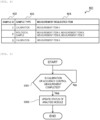
- the sample ID table 401 has columns of a sample ID 402, a sample type 403, and a measurement requested item 404. That is, the sample ID table 401 stores the sample type of the sample contained in the sample container 102 of each sample ID and the measurement item requested for the sample.
- the sample ID table 401 in FIG. 4 indicates that a calibrator is contained in the sample container 102 having the sample ID of 1 and the measurement item A is requested, and that a biological sample is contained in the sample container 102 having the sample ID of 2 and the measurement items A to D are requested.
- the control unit 101 determines whether the sample type is a biological sample. If the sample type is a biological sample, the process proceeds to S305. If the sample type is not a biological sample but a calibrator or an accuracy control sample, the process proceeds to S313, and calibration or accuracy control measurement is instructed to the analysis module 110.
- the control unit 101 determines whether there is a measurement requested item, for which calibration or accuracy control measurement is instructed, in the measurement requested item acquired in S303. If there is a measurement requested item for which calibration or accuracy control measurement is instructed, the process proceeds to S306, and if not, the process proceeds to S307. In determining whether there is a measurement requested item for which calibration or accuracy control measurement is instructed, for example, the analysis module table 201 is referred to.
- the control unit 101 prohibits execution of the measurement requested item for which calibration or accuracy control measurement is instructed.
- the control unit 101 causes the analysis module 110 to execute the measurement requested item. However, the measurement requested item whose execution is prohibited in S306 is not executed. In other words, the measurement requested item whose execution is not prohibited is permitted to be executed.
- the control unit 101 determines whether all the measurement requested items of the biological sample are executed. If all the measurement requested items are executed, the process proceeds to S309, and if there is an unexecuted measurement requested item, the process proceeds to S310.
- the control unit 101 causes the branching part 108 and the transport line 105 to transport the sample container 102 to the discharge part 106.
- the control unit 101 causes the branching part 108 and the return line 107 to transport the sample container 102 to the standby part 109.
- the control unit 101 determines whether the measurement requested item whose execution is prohibited in S306 is permitted. If there is a permitted measurement requested item, the process proceeds to S312, and if there is no permitted measurement requested item, processing of S311 is repeated.
- the control unit 101 causes the return line 107 and the transport line 105 to transport the sample container 102 to the analysis module 110. Thereafter, the measurement requested item is executed in S307.
- the control unit 101 updates a status of the analysis module in response to the instruction for calibration or accuracy control measurement. Specifically, content stored in the analysis module table 201 is updated to, for example, "calibration in execution". The content is updated only for a measurement item for which calibration or accuracy control measurement is instructed. After the update, the process proceeds to S309.
- the control unit 101 performs processing in FIG. 5 in parallel with the processing in FIG. 3 .
- the control unit 101 determines whether the instructed calibration or accuracy control measurement is completed. If the instructed calibration or accuracy control measurement is completed, the process proceeds to S502, and if not, processing of S501 is repeated.
- the control unit 101 updates the status of the analysis module in response to completion of the calibration or accuracy control measurement. Specifically, the content stored in the analysis module table 201 is updated to, for example, "measurable". The content is updated only for the measurement item for which calibration or accuracy control measurement is completed.
- an analysis processing speed can be improved. That is, only the execution of the measurement item for which the calibration or accuracy control measurement is instructed is prohibited, and the execution of the measurement item for which the calibration or accuracy control measurement is not instructed is permitted, and thus the measurable sample container 102 is analyzed without delay.
- the sample containers 102 for which execution of a measurement requested item is prohibited are collectively put on standby at the standby part 109, and thus it is possible to reduce a size of the automated analyzing device without providing, in each of the analysis modules 110, a space for putting the sample containers 102 on standby.
- the execution may be permitted for the measurement item whose execution is prohibited in S306 and which has a past measurement result of the calibration or accuracy control measurement.
- the execution may be permitted for the measurement item whose execution is prohibited in S306 and which has a past measurement result of the calibration or accuracy control measurement.
- By permitting the execution of the measurement item having a past measurement result it is possible to quickly analyze the biological sample without waiting for completion of the calibration or accuracy control measurement.
- whether to use the past measurement result of the calibration or accuracy control measurement may be switched by the user via a setting screen of the control unit 101.
- the control unit 101 may switch whether to use the past measurement result according to priority of the biological sample. For example, in order to quickly obtain a measurement result of a biological sample having high urgency and high priority, the past measurement result may be preferentially used.
- the execution of the measurement item, for which the calibration or accuracy control measurement is not instructed and which has no measurement result of the calibration or accuracy control measurement, may be prohibited. By prohibiting the execution of the measurement item having no measurement result of the calibration or accuracy control measurement, it is possible to prevent execution of erroneous analysis.
Landscapes
- Analytical Chemistry (AREA)
- Physics & Mathematics (AREA)
- Health & Medical Sciences (AREA)
- Life Sciences & Earth Sciences (AREA)
- Chemical & Material Sciences (AREA)
- Biochemistry (AREA)
- General Health & Medical Sciences (AREA)
- General Physics & Mathematics (AREA)
- Immunology (AREA)
- Pathology (AREA)
- Quality & Reliability (AREA)
- Engineering & Computer Science (AREA)
- Automatic Analysis And Handling Materials Therefor (AREA)
Abstract
Description
- The present invention relates to an automated analyzing device that analyzes a biological sample such as blood and urine.
- In an automated analyzing device that automatically performs qualitative or quantitative analysis on a specific component contained in a biological sample such as blood or urine of a subject, a calibrator or an accuracy control sample having a known concentration is periodically analyzed in order to maintain analysis accuracy. In order to prevent mixture of the calibrator or the accuracy control sample and the biological sample provided by the subject, the biological sample is generally controlled not to be analyzed until analysis of the calibrator or the accuracy control sample is completed.
- However, in an automated analyzing device including a plurality of analysis modules, when the biological sample is controlled not to be analyzed even in an analysis module in which analysis of the calibrator or the accuracy control sample is completed and analysis of the biological sample is possible, an analysis processing speed may decrease.
-
PTL 1 discloses that, in order not to reduce an analysis processing speed of an automated analyzing device, transport of a biological sample to an analysis module to which a calibrator or an accuracy control sample is transported is prohibited, and transport of the biological sample to other analysis modules is permitted. - PTL 1:
Japanese Patent No. 4919677 - However, in
PTL 1, consideration for a situation is not sufficient where a plurality of measurement items registered in an analysis module provided in an automated analyzing device include a measurement item for which analysis of a calibrator or an accuracy control sample is completed and analysis of a biological sample is possible. That is, even when the analysis of the calibrator or the accuracy control sample is completed, the measurement item registered in the analysis module to which the calibrator or the accuracy control sample is transported is not executed, and the analysis processing speed may decrease. - An object of the invention is to provide an automated analyzing device capable of improving the analysis processing speed.
- In order to achieve the above object, the invention provides an automated analyzing device including an analysis module configured to analyze a sample and a control unit configured to control the analysis module. The control unit controls the analysis module to prohibit analysis of a biological sample provided by a subject with respect to a measurement item for which calibration or accuracy control measurement is instructed among a plurality of measurement items registered in the analysis module, and to permit analysis of the biological sample with respect to a measurement item for which calibration or accuracy control measurement is not instructed.
- The invention also provides a control method for an automated analyzing device including an analysis module configured to analyze a sample, the control method including: controlling the analysis module to prohibit analysis of a biological sample provided by a subject with respect to a measurement item for which calibration or accuracy control measurement is instructed among a plurality of measurement items registered in the analysis module, and to permit analysis of the biological sample with respect to a measurement item for which calibration or accuracy control measurement is not instructed.
- According to the invention, it is possible to provide an automated analyzing device capable of improving an analysis processing speed.
-
- [
FIG. 1] FIG. 1 is a diagram illustrating a configuration example of an automated analyzing device. - [
FIG. 2] FIG. 2 is a diagram illustrating an example of an analysis module table. - [
FIG. 3] FIG. 3 is a flowchart illustrating a flow of processing according toembodiment 1. - [
FIG. 4] FIG. 4 is a diagram illustrating an example of a sample ID table. - [
FIG. 5] FIG. 5 is a flowchart illustrating a part of a flow of processing according toembodiment 1. - Hereinafter, embodiments of an automated analyzing device according to the invention will be described with reference to the accompanying drawings.
- A configuration example of an automated analyzing device will be described with reference to
FIG. 1 . The automated analyzing device includes aninput part 103, anID reader 104, atransport line 105, threeanalysis modules 110, abranching part 108, astandby part 109, adischarge part 106, and acontrol unit 101. The number ofanalysis modules 110 is not limited to three, and may be one or more. Hereinafter, each component will be described. - A
sample container 102 in which a biological sample such as blood or urine provided by a subject and a calibrator or an accuracy control sample that is a sample having a known concentration are contained is input to theinput part 103. Thesample container 102 may be placed on a dish-shaped carrier and input to theinput part 103. Further, the input of thesample container 102 to theinput part 103 may be manually performed by a user or may be automatically performed by an external transport system. Thesample container 102 input to theinput part 103 is transported to theID reader 104, theanalysis module 110, thebranching part 108, thestandby part 109, and thedischarge part 106 by thetransport line 105 and areturn line 107. Thereturn line 107 is a transport path for transporting thesample container 102 from downstream to upstream of thetransport line 105. - The
ID reader 104 is a device that reads a sample ID that is an identifier assigned to thesample container 102, and is, for example, a bar code reader or an RFID reader. The sample ID is associated in advance with a reception number or a subject name that is attribute information related to a sample contained in thesample container 102, a measurement requested item that is a requested measurement item, and the like. - The
analysis module 110 is a device that dispenses and analyzes the sample contained in thesample container 102 based on the measurement requested item. Since there are a wide variety of measurement items, several measurement items are registered in each of the plurality ofanalysis modules 110 and stored in the analysis module table 201 illustrated inFIG. 2 . The analysis module table 201 has columns of ananalysis module name 202 and ameasurement item 203, and stores the measurement items registered in each analysis module. In the analysis module table 201 inFIG. 2 , a measurement item A and a measurement item D are registered in an analysis module α, a measurement item B is registered in an analysis module β, and a measurement item C is registered in an analysis module γ. - In each of the
analysis modules 110, in order to maintain analysis accuracy for the registered measurement item, calibration using a calibrator or accuracy control measurement using an accuracy control sample is periodically performed. When the calibration or the accuracy control measurement is instructed, content stored in the analysis module table 201 is updated to, for example, "calibration in execution". When the calibration or the accuracy control measurement is completed, the measurement item registered in each analysis module becomes a measurable state, and the content stored in the analysis module table 201 is updated to "measurable". - The branching
part 108 is provided at a connection part between thetransport line 105 and thereturn line 107, and sets a transport destination of thesample container 102 to either thereturn line 107 or thedischarge part 106 based on an execution status of the measurement requested item associated with the sample ID of thesample container 102. That is, when all the measurement requested items associated with the sample ID are executed, thesample container 102 is transported to thedischarge part 106, and when there is an unexecuted measurement requested item, thesample container 102 is transported to thereturn line 107. - The
standby part 109 is provided in the middle of thereturn line 107, and puts thesample container 102 on standby. When a predetermined condition is satisfied, thesample container 102 put on standby at thestandby part 109 is transported to the upstream of thetransport line 105. - At the
discharge part 106, thesample container 102 on which all the measurement requested items are executed is discharged. The discharge of thesample container 102 from thedischarge part 106 may be manually performed by the user or may be automatically performed by an external transport system. - The
control unit 101 is a device that controls an operation of each component provided in the automated analyzing device and executes processing related to analysis, and is, for example, a computer. - A flow of processing executed in
embodiment 1 will be described step by step with reference toFIG. 3 . - The
sample container 102 in which a biological sample, a calibrator, or an accuracy control sample is contained is input to theinput part 103. A sample ID is assigned to thesample container 102. Thesample container 102 input to theinput part 103 is transported to theID reader 104 by thetransport line 105. - The
ID reader 104 reads the sample ID of thesample container 102. The read sample ID is transmitted to thecontrol unit 101. - The
control unit 101 collates the received sample ID with a sample ID table 401 illustrated inFIG. 4 , thereby acquiring a measurement requested item. The sample ID table 401 has columns of asample ID 402, asample type 403, and a measurement requesteditem 404. That is, the sample ID table 401 stores the sample type of the sample contained in thesample container 102 of each sample ID and the measurement item requested for the sample. The sample ID table 401 inFIG. 4 indicates that a calibrator is contained in thesample container 102 having the sample ID of 1 and the measurement item A is requested, and that a biological sample is contained in thesample container 102 having the sample ID of 2 and the measurement items A to D are requested. - The
control unit 101 determines whether the sample type is a biological sample. If the sample type is a biological sample, the process proceeds to S305. If the sample type is not a biological sample but a calibrator or an accuracy control sample, the process proceeds to S313, and calibration or accuracy control measurement is instructed to theanalysis module 110. - The
control unit 101 determines whether there is a measurement requested item, for which calibration or accuracy control measurement is instructed, in the measurement requested item acquired in S303. If there is a measurement requested item for which calibration or accuracy control measurement is instructed, the process proceeds to S306, and if not, the process proceeds to S307. In determining whether there is a measurement requested item for which calibration or accuracy control measurement is instructed, for example, the analysis module table 201 is referred to. - The
control unit 101 prohibits execution of the measurement requested item for which calibration or accuracy control measurement is instructed. - The
control unit 101 causes theanalysis module 110 to execute the measurement requested item. However, the measurement requested item whose execution is prohibited in S306 is not executed. In other words, the measurement requested item whose execution is not prohibited is permitted to be executed. - The
control unit 101 determines whether all the measurement requested items of the biological sample are executed. If all the measurement requested items are executed, the process proceeds to S309, and if there is an unexecuted measurement requested item, the process proceeds to S310. - The
control unit 101 causes the branchingpart 108 and thetransport line 105 to transport thesample container 102 to thedischarge part 106. - The
control unit 101 causes the branchingpart 108 and thereturn line 107 to transport thesample container 102 to thestandby part 109. - The
control unit 101 determines whether the measurement requested item whose execution is prohibited in S306 is permitted. If there is a permitted measurement requested item, the process proceeds to S312, and if there is no permitted measurement requested item, processing of S311 is repeated. - The
control unit 101 causes thereturn line 107 and thetransport line 105 to transport thesample container 102 to theanalysis module 110. Thereafter, the measurement requested item is executed in S307. - The
control unit 101 updates a status of the analysis module in response to the instruction for calibration or accuracy control measurement. Specifically, content stored in the analysis module table 201 is updated to, for example, "calibration in execution". The content is updated only for a measurement item for which calibration or accuracy control measurement is instructed. After the update, the process proceeds to S309. - The
control unit 101 performs processing inFIG. 5 in parallel with the processing inFIG. 3 . - The
control unit 101 determines whether the instructed calibration or accuracy control measurement is completed. If the instructed calibration or accuracy control measurement is completed, the process proceeds to S502, and if not, processing of S501 is repeated. - The
control unit 101 updates the status of the analysis module in response to completion of the calibration or accuracy control measurement. Specifically, the content stored in the analysis module table 201 is updated to, for example, "measurable". The content is updated only for the measurement item for which calibration or accuracy control measurement is completed. - According to the flow of the processing described above, an analysis processing speed can be improved. That is, only the execution of the measurement item for which the calibration or accuracy control measurement is instructed is prohibited, and the execution of the measurement item for which the calibration or accuracy control measurement is not instructed is permitted, and thus the
measurable sample container 102 is analyzed without delay. - In the automated analyzing device including a plurality of analysis modules, the
sample containers 102 for which execution of a measurement requested item is prohibited are collectively put on standby at thestandby part 109, and thus it is possible to reduce a size of the automated analyzing device without providing, in each of theanalysis modules 110, a space for putting thesample containers 102 on standby. - The execution may be permitted for the measurement item whose execution is prohibited in S306 and which has a past measurement result of the calibration or accuracy control measurement. By permitting the execution of the measurement item having a past measurement result, it is possible to quickly analyze the biological sample without waiting for completion of the calibration or accuracy control measurement. However, whether to use the past measurement result of the calibration or accuracy control measurement may be switched by the user via a setting screen of the
control unit 101. Thecontrol unit 101 may switch whether to use the past measurement result according to priority of the biological sample. For example, in order to quickly obtain a measurement result of a biological sample having high urgency and high priority, the past measurement result may be preferentially used. - The execution of the measurement item, for which the calibration or accuracy control measurement is not instructed and which has no measurement result of the calibration or accuracy control measurement, may be prohibited. By prohibiting the execution of the measurement item having no measurement result of the calibration or accuracy control measurement, it is possible to prevent execution of erroneous analysis.
- The embodiment of the invention has been described above. The invention is not limited to the above-described embodiment, and the components may be modified without departing from the gist of the invention. The plurality of components disclosed in the above-described embodiment may be combined as appropriate. Further, some components may be deleted from all the components shown in the above-described embodiment.
-
- 101:
- control unit
- 102:
- sample container
- 103:
- input part
- 104:
- ID reader
- 105:
- transport line
- 106:
- discharge part
- 107:
- return Line
- 108:
- branching part
- 109:
- standby part
- 110:
- analysis module
- 201:
- analysis module table
- 202:
- analysis module name
- 203:
- measurement item
- 401:
- sample ID table
- 402:
- sample ID
- 403:
- sample type
- 404:
- measurement requested item
Claims (6)
- An automated analyzing device comprising:an analysis module configured to analyze a sample; anda control unit configured to control the analysis module, whereinthe control unit controls the analysis module to prohibit analysis of a biological sample provided by a subject with respect to a measurement item for which calibration or accuracy control measurement is instructed among a plurality of measurement items registered in the analysis module, and to permit analysis of the biological sample with respect to a measurement item for which calibration or accuracy control measurement is not instructed.
- The automated analyzing device according to claim 1, wherein
the control unit puts the biological sample, for which analysis is prohibited, on standby in a standby part. - The automated analyzing device according to claim 2, wherein
when the calibration or the accuracy control measurement is completed, the control unit causes the biological sample, for which analysis is prohibited, to be transported from the standby part to the analysis module. - The automated analyzing device according to claim 1, wherein
the control unit controls the analysis module to permit analysis of the biological sample with respect to a measurement item for which the calibration or the accuracy control measurement is instructed and which has a past measurement result of the calibration or the accuracy control measurement. - The automated analyzing device according to claim 1, wherein
the control unit controls the analysis module to prohibit analysis of the biological sample with respect to a measurement item for which the calibration or the accuracy control measurement is not instructed and which has no measurement result of the calibration or the accuracy control measurement. - A control method for an automated analyzing device including an analysis module configured to analyze a sample, the control method comprising:
controlling the analysis module to prohibit analysis of a biological sample provided by a subject with respect to a measurement item for which calibration or accuracy control measurement is instructed among a plurality of measurement items registered in the analysis module, and to permit analysis of the biological sample with respect to a measurement item for which calibration or accuracy control measurement is not instructed.
Applications Claiming Priority (2)
| Application Number | Priority Date | Filing Date | Title |
|---|---|---|---|
| JP2021146034 | 2021-09-08 | ||
| PCT/JP2022/026252 WO2023037732A1 (en) | 2021-09-08 | 2022-06-30 | Automated analyzing device, and control method for same |
Publications (2)
| Publication Number | Publication Date |
|---|---|
| EP4400843A1 true EP4400843A1 (en) | 2024-07-17 |
| EP4400843A4 EP4400843A4 (en) | 2025-08-06 |
Family
ID=85506492
Family Applications (1)
| Application Number | Title | Priority Date | Filing Date |
|---|---|---|---|
| EP22867056.8A Pending EP4400843A4 (en) | 2021-09-08 | 2022-06-30 | AUTOMATED ANALYSIS DEVICE AND CONTROL METHODS THEREFOR |
Country Status (5)
| Country | Link |
|---|---|
| US (1) | US20240353435A1 (en) |
| EP (1) | EP4400843A4 (en) |
| JP (1) | JP7673216B2 (en) |
| CN (1) | CN117795346A (en) |
| WO (1) | WO2023037732A1 (en) |
Family Cites Families (13)
| Publication number | Priority date | Publication date | Assignee | Title |
|---|---|---|---|---|
| JP2996860B2 (en) * | 1994-03-18 | 2000-01-11 | 株式会社日立製作所 | Automatic analyzer |
| JP2002350970A (en) * | 2001-05-23 | 2002-12-04 | East Japan Railway Co | Camera housing |
| JP4456962B2 (en) * | 2004-09-02 | 2010-04-28 | 株式会社キーエンス | SAMPLE DISPLAY DEVICE, SAMPLE DISPLAY DEVICE OPERATION METHOD, SAMPLE DISPLAY DEVICE OPERATION PROGRAM, AND COMPUTER-READABLE RECORDING MEDIUM OR RECORDED DEVICE |
| JP2006038881A (en) * | 2005-10-20 | 2006-02-09 | Hitachi Ltd | Automated analysis system for biological samples |
| JP4919677B2 (en) * | 2006-03-07 | 2012-04-18 | 株式会社日立ハイテクノロジーズ | Automatic analysis system and method for controlling the automatic analysis system |
| US20080006653A1 (en) * | 2006-03-13 | 2008-01-10 | Biomachines, Inc. | Small volume liquid handling system |
| JP2008175791A (en) * | 2007-01-22 | 2008-07-31 | Juki Corp | Dispensing device |
| JP5210903B2 (en) * | 2009-01-30 | 2013-06-12 | 株式会社日立ハイテクノロジーズ | Sample analyzer |
| US9046504B2 (en) * | 2011-02-24 | 2015-06-02 | Kabushiki Kaisha Toshiba | Automatic analysis apparatus |
| JP6886243B2 (en) * | 2016-02-25 | 2021-06-16 | 株式会社日立ハイテク | Automatic analyzer |
| JP7075923B2 (en) * | 2017-02-22 | 2022-05-26 | 株式会社日立ハイテク | Automatic analyzer |
| JP6934244B2 (en) * | 2017-06-19 | 2021-09-15 | 国立大学法人東京工業大学 | Telescopic robot arm |
| EP3640646A1 (en) * | 2018-10-16 | 2020-04-22 | F. Hoffmann-La Roche AG | Method of operating an analytical laboratory |
-
2022
- 2022-06-30 EP EP22867056.8A patent/EP4400843A4/en active Pending
- 2022-06-30 WO PCT/JP2022/026252 patent/WO2023037732A1/en not_active Ceased
- 2022-06-30 CN CN202280055387.3A patent/CN117795346A/en active Pending
- 2022-06-30 US US18/686,198 patent/US20240353435A1/en active Pending
- 2022-06-30 JP JP2023546797A patent/JP7673216B2/en active Active
Also Published As
| Publication number | Publication date |
|---|---|
| US20240353435A1 (en) | 2024-10-24 |
| CN117795346A (en) | 2024-03-29 |
| JPWO2023037732A1 (en) | 2023-03-16 |
| JP7673216B2 (en) | 2025-05-08 |
| EP4400843A4 (en) | 2025-08-06 |
| WO2023037732A1 (en) | 2023-03-16 |
Similar Documents
| Publication | Publication Date | Title |
|---|---|---|
| US10816564B2 (en) | Sample test automation system | |
| JP4558017B2 (en) | Automatic analyzer and method of using the automatic analyzer | |
| EP2450711A1 (en) | Analaysis system for analyzing biological samples | |
| US20130039809A1 (en) | Automatic analyzer | |
| US20120109529A1 (en) | Sample processing apparatus and non-transitory storage medium | |
| JPWO2010122718A1 (en) | Automatic analyzer | |
| CN110073223B (en) | automatic analysis device | |
| JP7760675B2 (en) | Automated Analysis System | |
| US9483048B2 (en) | Sample transport system and method for controlling the same | |
| US11971424B2 (en) | Automatic analyzer | |
| CN114556107B (en) | A sample analysis system and sample scheduling method thereof | |
| EP3751284B1 (en) | Method and laboratory system to provide control samples for validating a diagnostic test | |
| JP2009281752A (en) | Automatic analyzer | |
| JP6037783B2 (en) | Automatic analysis apparatus, automatic analysis adjustment support method, and automatic analysis adjustment support program | |
| JP2013024691A (en) | Autoanalyzer | |
| JP2947917B2 (en) | Laboratory test system | |
| US20240353435A1 (en) | Automated Analyzing Device, and Control Method for Same | |
| EP2485055B1 (en) | Specimen preprocessing system | |
| CN116888679A (en) | Methods and systems for managing sample priority | |
| EP4317981A1 (en) | Automated analysis device | |
| JP2007240223A (en) | Automatic analyzer | |
| JPH11304807A (en) | Sample processing system | |
| JP7705455B2 (en) | Automatic analyzer and reagent management method | |
| US20240168042A1 (en) | Method for optimizing laboratory system | |
| CN112345779B (en) | A sample analysis system, device and quality control processing method |
Legal Events
| Date | Code | Title | Description |
|---|---|---|---|
| STAA | Information on the status of an ep patent application or granted ep patent |
Free format text: STATUS: THE INTERNATIONAL PUBLICATION HAS BEEN MADE |
|
| PUAI | Public reference made under article 153(3) epc to a published international application that has entered the european phase |
Free format text: ORIGINAL CODE: 0009012 |
|
| STAA | Information on the status of an ep patent application or granted ep patent |
Free format text: STATUS: REQUEST FOR EXAMINATION WAS MADE |
|
| 17P | Request for examination filed |
Effective date: 20240215 |
|
| AK | Designated contracting states |
Kind code of ref document: A1 Designated state(s): AL AT BE BG CH CY CZ DE DK EE ES FI FR GB GR HR HU IE IS IT LI LT LU LV MC MK MT NL NO PL PT RO RS SE SI SK SM TR |
|
| DAV | Request for validation of the european patent (deleted) | ||
| DAX | Request for extension of the european patent (deleted) | ||
| A4 | Supplementary search report drawn up and despatched |
Effective date: 20250708 |
|
| RIC1 | Information provided on ipc code assigned before grant |
Ipc: G01N 35/00 20060101AFI20250702BHEP |