EP4400842A1 - Automatic analysis device and method for operating automatic analysis device - Google Patents
Automatic analysis device and method for operating automatic analysis device Download PDFInfo
- Publication number
- EP4400842A1 EP4400842A1 EP22864187.4A EP22864187A EP4400842A1 EP 4400842 A1 EP4400842 A1 EP 4400842A1 EP 22864187 A EP22864187 A EP 22864187A EP 4400842 A1 EP4400842 A1 EP 4400842A1
- Authority
- EP
- European Patent Office
- Prior art keywords
- analysis
- reagent
- group
- item group
- automatic analyzer
- Prior art date
- Legal status (The legal status is an assumption and is not a legal conclusion. Google has not performed a legal analysis and makes no representation as to the accuracy of the status listed.)
- Pending
Links
Images



Classifications
-
- G—PHYSICS
- G01—MEASURING; TESTING
- G01N—INVESTIGATING OR ANALYSING MATERIALS BY DETERMINING THEIR CHEMICAL OR PHYSICAL PROPERTIES
- G01N35/00—Automatic analysis not limited to methods or materials provided for in any single one of groups G01N1/00 - G01N33/00; Handling materials therefor
- G01N35/00584—Control arrangements for automatic analysers
- G01N35/00594—Quality control, including calibration or testing of components of the analyser
- G01N35/00712—Automatic status testing, e.g. at start-up or periodic
-
- G—PHYSICS
- G01—MEASURING; TESTING
- G01N—INVESTIGATING OR ANALYSING MATERIALS BY DETERMINING THEIR CHEMICAL OR PHYSICAL PROPERTIES
- G01N35/00—Automatic analysis not limited to methods or materials provided for in any single one of groups G01N1/00 - G01N33/00; Handling materials therefor
- G01N35/02—Automatic analysis not limited to methods or materials provided for in any single one of groups G01N1/00 - G01N33/00; Handling materials therefor using a plurality of sample containers moved by a conveyor system past one or more treatment or analysis stations
- G01N35/025—Automatic analysis not limited to methods or materials provided for in any single one of groups G01N1/00 - G01N33/00; Handling materials therefor using a plurality of sample containers moved by a conveyor system past one or more treatment or analysis stations having a carousel or turntable for reaction cells or cuvettes
-
- G—PHYSICS
- G01—MEASURING; TESTING
- G01N—INVESTIGATING OR ANALYSING MATERIALS BY DETERMINING THEIR CHEMICAL OR PHYSICAL PROPERTIES
- G01N35/00—Automatic analysis not limited to methods or materials provided for in any single one of groups G01N1/00 - G01N33/00; Handling materials therefor
- G01N35/10—Devices for transferring samples or any liquids to, in, or from, the analysis apparatus, e.g. suction devices, injection devices
- G01N35/1065—Multiple transfer devices
- G01N35/1067—Multiple transfer devices for transfer to or from containers having different spacing
-
- G—PHYSICS
- G01—MEASURING; TESTING
- G01N—INVESTIGATING OR ANALYSING MATERIALS BY DETERMINING THEIR CHEMICAL OR PHYSICAL PROPERTIES
- G01N35/00—Automatic analysis not limited to methods or materials provided for in any single one of groups G01N1/00 - G01N33/00; Handling materials therefor
- G01N35/00584—Control arrangements for automatic analysers
- G01N35/00594—Quality control, including calibration or testing of components of the analyser
- G01N35/00613—Quality control
- G01N35/00663—Quality control of consumables
- G01N2035/00673—Quality control of consumables of reagents
-
- G—PHYSICS
- G01—MEASURING; TESTING
- G01N—INVESTIGATING OR ANALYSING MATERIALS BY DETERMINING THEIR CHEMICAL OR PHYSICAL PROPERTIES
- G01N35/00—Automatic analysis not limited to methods or materials provided for in any single one of groups G01N1/00 - G01N33/00; Handling materials therefor
- G01N35/02—Automatic analysis not limited to methods or materials provided for in any single one of groups G01N1/00 - G01N33/00; Handling materials therefor using a plurality of sample containers moved by a conveyor system past one or more treatment or analysis stations
- G01N35/04—Details of the conveyor system
- G01N2035/0439—Rotary sample carriers, i.e. carousels
- G01N2035/0446—Combinations of the above
-
- G—PHYSICS
- G01—MEASURING; TESTING
- G01N—INVESTIGATING OR ANALYSING MATERIALS BY DETERMINING THEIR CHEMICAL OR PHYSICAL PROPERTIES
- G01N35/00—Automatic analysis not limited to methods or materials provided for in any single one of groups G01N1/00 - G01N33/00; Handling materials therefor
- G01N35/02—Automatic analysis not limited to methods or materials provided for in any single one of groups G01N1/00 - G01N33/00; Handling materials therefor using a plurality of sample containers moved by a conveyor system past one or more treatment or analysis stations
- G01N35/04—Details of the conveyor system
- G01N2035/0439—Rotary sample carriers, i.e. carousels
- G01N2035/0453—Multiple carousels working in parallel
-
- G—PHYSICS
- G01—MEASURING; TESTING
- G01N—INVESTIGATING OR ANALYSING MATERIALS BY DETERMINING THEIR CHEMICAL OR PHYSICAL PROPERTIES
- G01N35/00—Automatic analysis not limited to methods or materials provided for in any single one of groups G01N1/00 - G01N33/00; Handling materials therefor
- G01N35/02—Automatic analysis not limited to methods or materials provided for in any single one of groups G01N1/00 - G01N33/00; Handling materials therefor using a plurality of sample containers moved by a conveyor system past one or more treatment or analysis stations
- G01N35/04—Details of the conveyor system
- G01N2035/0496—Other details
- G01N2035/0498—Drawers used as storage or dispensing means for vessels or cuvettes
-
- G—PHYSICS
- G01—MEASURING; TESTING
- G01N—INVESTIGATING OR ANALYSING MATERIALS BY DETERMINING THEIR CHEMICAL OR PHYSICAL PROPERTIES
- G01N35/00—Automatic analysis not limited to methods or materials provided for in any single one of groups G01N1/00 - G01N33/00; Handling materials therefor
- G01N35/10—Devices for transferring samples or any liquids to, in, or from, the analysis apparatus, e.g. suction devices, injection devices
- G01N35/1065—Multiple transfer devices
- G01N2035/1076—Multiple transfer devices plurality or independently movable heads
Definitions
- the present invention relates to an automatic analyzer and an operation method for the automatic analyzer.
- an automatic analyzer that has two power-saving mode functions to stop mechanism operation, such as mode 1 in which operation of a cleaning mechanism is stopped during a waiting time in which analysis modules after measurement end do not perform measurement and mode 2 in which a light source lamp is stopped during the waiting time.
- Patent Document 1 JP-2015-129659-A
- the present invention provides an automatic analyzer that can decrease waiting time for a user and reduce also running costs and an operation method for the automatic analyzer.
- waiting time for a user can be decreased and running costs can also be reduced.
- Embodiments of an automatic analyzer and an operation method for the automatic analyzer according to the present invention will be described with use of FIG. 1 to FIG. 7 .
- constituent elements including elementary steps and so forth
- constituent elements thereof are not necessarily indispensable except for the case in which an explicit statement is particularly made, the case in which the constituent element is obviously indispensable in principle, and so forth.
- the same or corresponding constituent elements are given the same or similar numerals and repeated description is omitted regarding these constituent elements in some cases.
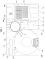
- FIG. 1 is a diagram schematically illustrating a plan view of the automatic analyzer.
- reaction vessels 111 line up on a circumference in an incubator (reaction disk) 101. Common vessels are used in all reactions as the reaction vessels 111 and the reaction vessels 111 are disposable.
- the incubator 101 is controlled by a drive mechanism such as a motor in such a manner as to be rotationally driven by a distance equivalent to a length of predetermined number of reaction vessels 111 in one cycle.
- a plurality of reagent bottles and sample vessels can be placed on a circumference in a reagent/sample common disk 102.
- reagent bottles are located on the inner circumferential side of sample vessels.
- sample vessels may be located on the inner circumferential side of reagent bottles, or a configuration may be employed in which reagent bottles and sample vessels are located without division based on the inner circumferential side and the outer circumferential side.
- first reagents required only in analysis for a first analysis item group biological items
- second reagents required only in analysis for a second analysis item group immunological items
- a first dispensing mechanism 103 and a second dispensing mechanism 104 that can rotate and vertically move are installed between the incubator 101 and the reagent/sample common disk 102, and each include a dispensing nozzle.
- the first dispensing mechanism 103 and the second dispensing mechanism 104 are separately used in inspections in different analysis processes.
- the necessity to prevent contamination between samples is high in the second dispensing mechanism 104 for immunological inspection and therefore dispensing is performed with use of a disposable dispensing tip 110 in the second dispensing mechanism 104.
- the dispensing mechanism 103 In the first dispensing mechanism 103, a sample and a reagent for biochemical inspection are dispensed. In the second dispensing mechanism 104, a sample and a reagent for immunological inspection are dispensed. Regarding a sample for which measurement is performed for inspections of both biochemical inspection and immunological inspection, the dispensing mechanism makes access and performs dispensing in both the first dispensing mechanism 103 and the second dispensing mechanism 104.
- the dispensing nozzle moves while drawing a circular arc around a rotation axis and performs sample dispensing from a sample vessel to a reaction vessel installed in the incubator 101.
- a sample aspiration position and a reagent aspiration position on the reagent/sample common disk 102, a first dispensing position and a second dispensing position on the incubator 101, and a cleaning tank for cleaning the dispensing nozzle exist.
- a dispensing tip mounting position and a dispensing tip discarding position also exist on the trajectory because the dispensing tip 110 is used.
- the first dispensing mechanism 103 and the second dispensing mechanism 104 are disposed in such a manner that physical interference does not occur between the trajectories of the respective dispensing nozzles and between the respective mechanisms.
- a sample and a reagent are aspirated by the dispensing nozzle or the dispensing tip mounted on the dispensing nozzle, the sample and the reagent are stirred and mixed in a reaction vessel installed in the incubator 101, by aspiration-discharge operation of the dispensing nozzle or the dispensing tip.
- the reaction vessel that houses a reacted liquid resulting from the mixing of the sample and the reagent is managed at a predetermined temperature by the incubator 101 and reaction is promoted for a predetermined time.
- a reagent stirring mechanism 105 as stirring means is set around the reagent/sample common disk 102.
- This reagent stirring mechanism 105 moves to an area above the reagent vessel in which a magnetic particle solution that should be stirred is put, and lowers a magnetic particle stirring element of the reagent stirring mechanism 105 to stir the magnetic particle solution by rotating this stirring element.
- the magnetic particles are stirred immediately before the reagent is dispensed.
- a spectrophotometer 107 for biochemical inspection is disposed around the incubator 101.
- the spectrophotometer 107 includes a light source and a detector (neither is omitted for convenience of illustration) and measures the absorbance of a reacted liquid resulting from mixing of a sample and a reagent, by dispersing and detecting transmitted light obtained through irradiating the reacted liquid with the light source.
- the reacted liquid resulting from reaction for a predetermined time by the incubator 101 can be brought to a detection mechanism 108 for immunological inspection by a detector syringe 106 and be measured.
- a detection mechanism 108 for immunological inspection there are systems in which electrochemiluminescence or chemiluminescence is employed as the principle as a system that detects a labeled substance.
- a second liquid container 114, a labeled substance, and the structure and properties of a detection area suitable for each are selected, and the amount of luminescence that derives from luminescence reaction of the labeled substance is measured with use of a photomultiplier tube as the detector.
- the reaction vessel about which measurement of the absorbance has been completed in the incubator 101 is discarded into a dispensing tip/reaction vessel discarding box 112 by a dispensing tip/reaction vessel transporting mechanism 109. Movement of the reaction vessel in which the reacted liquid resulting from reaction for a predetermined time by the incubator 101 is put to the detection mechanism 108 and movement of the reaction vessel about which measurement has been completed in the detection mechanism 108 to the dispensing tip/reaction vessel discarding box 112 are also performed by the dispensing tip/reaction vessel transporting mechanism 109.
- a cleaning liquid container 115 is used in order to clean the first dispensing mechanism 103 or the second dispensing mechanism 104.
- a control part 116 is connected to pieces of equipment in the above-described automatic analyzer 100 and controls operation of the respective pieces of equipment and mechanisms in the automatic analyzer 100, such as rotational driving of the incubator 101, rotational operation of the reagent/sample common disk 102, and operations of driving, sample aspiration, and sample discharge of a sample nozzle.
- FIG. 1 illustration is made with omission of the connection between the respective mechanisms that configure the automatic analyzer and the control part 116 for simplification of illustration.
- the control part 116 is a computer including a CPU and.a memory, and performs computation processing to obtain the concentration of a predetermined component in a sample from a detection result of the spectrophotometer 107 or the detection mechanism 108.
- the control of the operation of the respective pieces of equipment by the control part 116 is performed based on various programs recorded in a storage device.
- various.parameters input through an input device, information on a measurement-target sample (information by sample type, and so forth), measurement results, and so forth are stored besides various programs used for measurement of a sample.
- a storage part 117 is connected to the control part 116, and stores information required to control the automatic analyzer 100, the current situation of the automatic analyzer 100, and so forth and affects operation of the control part 116.
- control processing of operation performed in the control part 116 may be marshaled into one program or the respective kinds of control processing may be separated into a plurality of programs, or the control processing may be a combination of them. Moreover, part or all of the programs may be implemented by dedicated hardware or may be modularized.
- a display part 118 is display equipment, such as a liquid crystal display, that displays, for an operator, an input screen of various parameters and setting, analysis inspection data of first inspection or re-inspection, a measurement result, and various kinds of information in the automatic analyzer 100, such as reagent information.
- the display part 118 can be made into a touch panel system that doubles as an input part.
- FIG. 1 description has been made about the form in which reagents and samples are housed in one disk as the reagent/sample common disk.
- dispensing mechanisms one or more dispensing mechanisms for exclusive use for reagent dispensing and one or more dispensing mechanisms for sample dispensing can be each disposed for exclusive use.
- the first analysis item group is biochemical items and the second analysis item group is immunological items.
- the analysis item groups are not limited to this combination and other items such as an electrolyte and blood can be employed as another analysis item group.
- FIG. 2 is a view illustrating a mechanism classification table 201 in which a classification of a first mechanism required only in analysis for the first analysis item group, a second mechanism required only in analysis for the second analysis item group, and a third mechanism required in both analysis for the first analysis item group and analysis for the second analysis item group is stored in the automatic analyzer 100 illustrated in FIG. 1 .
- This table is stored in the storage part 117.
- the first analysis item group is biochemical items and the second analysis.item group is immunological items.
- the first mechanism is classified as a mechanism for biochemical items and the second mechanism is classified as a mechanism for immunological items.
- a first mechanism group 202 is configured by mechanisms used only in analysis for the first analysis item group and is formed from the first dispensing mechanism 103 and the spectrophotometer 107. Besides, for example, there are a syringe for the first dispensing mechanism 103 and so forth.
- a second mechanism group 203 is configured by mechanisms used only in analysis for the second analysis item group and is formed from the second dispensing mechanism 104, the detector syringe 106, the detection mechanism 108, the dispensing tip 110, and the second liquid container 114. Besides, for example, there are a syringe for the second dispensing mechanism 104, system reagents, and a system reagent supply system.
- a common mechanism group 204 is configured by mechanisms used in analysis for both the first analysis item group and the second analysis item group and is formed from the incubator 101, the reagent/sample common disk 102, the reagent stirring mechanism 105, the dispensing tip/reaction vessel transporting mechanism 109, the reaction vessel 111, the dispensing tip/reaction vessel discarding box 112, a waste liquid tank 113, and the cleaning liquid container 115.
- the incubator 101 the reagent/sample common disk 102
- the reagent stirring mechanism 105 the dispensing tip/reaction vessel transporting mechanism 109
- the reaction vessel 111 the reaction vessel 111
- the dispensing tip/reaction vessel discarding box 112 a waste liquid tank 113
- the cleaning liquid container 115 for example, there are system water and a system water supply system.
- first mechanism group 202 second mechanism group 203, and common mechanism group 204 are disposed in the casing of the automatic analyzer 100.
- control part 116 of the present embodiment activates the second mechanism group 203 and the common mechanism group 204 without activating the first mechanism group 202 when analysis for the biochemical items is not required, and activates the first mechanism group 202 and the common mechanism group 204 without activating the second mechanism group 203 when analysis for the immunological items is not required.
- control part 116 activates only the second mechanism group 203 and the common mechanism group 204 when the first reagent for the biochemical item is not housed in the reagent/sample common disk 102, and activates only the first mechanism group 202 and the common mechanism group 204 when the second reagent for the immunological item is not housed in the reagent/sample common disk 102.
- control part 116 activates only the second mechanism group 203 and the common mechanism group 204 when it is decided that an abnormality has occurred in the first mechanism group 202, and activates only the first mechanism group 202 and the common mechanism group 204 when it is decided that an abnormality has occurred in the second mechanism group 203.
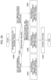
- FIG. 3A is a flowchart that sets the analysis mechanism status according to the installed reagent.
- FIG. 3B is a flowchart that sets the analysis mechanism status according to the mechanism status.
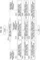
- FIG. 3C is a flowchart that decides which mechanism to be activated, according to the analysis mechanism status.
- FIG. 3A and FIG. 3B to be described below are flowcharts that flow at the time of reagent registration or at the time of occurrence of an abnormality.
- the control part 116 may operate in the classification that has been already determined.
- the control part 116 acquires all pieces of information on the reagents that have been installed in the reagent/sample common disk 102 and been registered, checks the acquired reagent information (step (hereinafter, described as "S") 302), and decides which status of "only biochemical reagent,” "both biochemical reagent and immunological reagent,” and "only immunological reagent” the installed reagents are in (S303).
- control part 116 sets the respective mechanism statuses to "analysis is possible” for the first mechanism group 202 and “analysis is impossible” for the second mechanism group 203 (S304).
- control part 116 sets the respective mechanism statuses to "analysis is possible” for both the first mechanism group 202 and the second mechanism group 203 (S305).
- control part 116 sets the respective mechanism statuses to "analysis is impossible” for the first mechanism group 202 and “analysis is possible” for the second mechanism group 203 (S306).
- the mechanism statuses displayed on a system overview screen like ones illustrated in FIG. 4 and FIG. 5 are updated (S322).
- FIG. 3B The flow of FIG. 3B may be performed after the flow of FIG. 3A continuously or may be performed at a different timing from it.
- the control part 116 acquires all pieces of information on the status of the first mechanism group 202, the second mechanism group 203, and the common mechanism group 204 (S307), and decides which of "abnormality exists only in first mechanism group 202," “abnormality exists only in second mechanism group 203,” and “mechanism abnormality does not exist” the status of the first mechanism group 202 and the second mechanism group 203 is (S308).
- a performance check of the detection mechanism 108 is performed at the time of analysis preparation operation and, when an abnormality exists in the temperature, a signal value, or the like, the control part 116 sets the status of the second mechanism group 203 to the status in which analysis is impossible (S309). Furthermore, the control part 116 sets the status of the second mechanism group 203 to the status in which analysis is impossible also when a pressure abnormality or sensor abnormality is sensed in the second dispensing mechanism 104 or the detector syringe 106. Besides, also when insufficiency of the capacity of the dispensing tip 110 or the second liquid container 114 has occurred, the status of the second mechanism group 203 is set to the status in which analysis is impossible (S309). In these occasions, the control part 116 sets the first mechanism group 202 to "analysis is possible.”
- the status of the first mechanism group 202 and the status of the second mechanism group 203 are set to the status in which analysis is possible (S310).
- the control part 116 sets the status of the first mechanism group 202 to the status in which analysis is impossible (S311). Furthermore, also when a pressure abnormality or sensor abnormality is sensed in the first dispensing mechanism 103, the control part 116 sets the status of the first mechanism group 202 to the status in which analysis is impossible (S311). In these occasions, the control part 116 sets the second mechanism group 203 to "analysis is possible.”
- the mechanism statuses displayed on the system overview screen like those illustrated in FIG. 4 and FIG. 5 are updated (S323).
- FIG. 3C will be described.
- the flow of FIG. 3C may be performed after the flow of FIG. 3B continuously or may be performed at a different timing from it.
- the control part 116 checks the analysis possibility/impossibility status and decides which of "analysis is possible” and “analysis is impossible” the first mechanism group 202 and the second mechanism group 203 are set to (S312).
- the control part 116 performs the analysis preparation operation only in the biochemical measuring system (first mechanism group 202 + common mechanism group 204) (S313), performs analysis operation only in the biochemical measuring system (S314), and performs analysis end operation only in the biochemical measurement system (S315) to end the operation.
- the control part 116 performs the analysis preparation operation in the biochemical and immunological measuring systems (first mechanism group 202 + second mechanism group 203 + common mechanism group 204) (S316), performs the analysis operation in the biobiochemical and immunological measuring systems (S317), and performs the analysis end operation in the biochemical and immunological measuring systems (S318) to end the operation.
- control part 116 performs the analysis preparation operation only in the immunological measuring system (second mechanism group 203 + common mechanism group 204) (S319), performs the analysis operation only in the immunological measuring system (S320), and performs the analysis end operation only in the immunological measurement system (S321) to end the operation.
- the first mechanism group or the second mechanism group is recognized as the status in which analysis is impossible.
- Analysis items to be measured by the mechanism that has become the status in which analysis is impossible are skipped and analysis is continued regarding analysis items to be measured by the mechanism that is still capable of analysis. Stop of the analysis can be avoided as much as possible and measurement of measurable items can be continued.
- the analysis possibility/impossibility status is acquired from a matrix diagram illustrated in FIG. 7 .
- the analysis possibility/impossibility status is determined from both statuses of the mechanism status and the registered reagent status.
- the mechanism status is acquired by the flow of FIG. 3B and the registered reagent status is acquired by the flow of FIG. 3A .
- the control part 116 obeys the respective statuses at the timing of operation.
- FIG. 4 and FIG. 5 are examples of the system overview screen of the automatic analyzer.
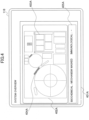
- FIG. 6 is an example of a reagent overview screen of the automatic analyzer.
- the timing when the screen of FIG. 4 to FIG. 6 is displayed is set to a timing after S309, S310, or S311 in FIG. 3B and timings before and after S312.
- the timing is not limited thereto.
- control part 116 causes the display part 118 to display a system overview screen 401A showing whether or not to activate the first mechanism group 202 or a system overview screen 401B showing whether or not to activate the second mechanism group 203.
- mechanism view screens 402A and 402B are displayed, and mechanisms 403A and 403B capable of analysis and mechanisms 404A and 404B incapable of analysis are each displayed.
- the mechanisms 403A and 403B capable of analysis and the mechanisms 404A and 404B incapable of analysis are displayed in such a manner as to be allowed to be discriminated.
- the mechanisms 404A and 404B incapable of analysis are displayed with oblique lines and are displayed differently from normal display like that of the mechanisms 403A and 403B capable of analysis.
- the system status of the first mechanism group 202 and the second mechanism group 203 is displayed in the respective mechanism status display screens 405A and 405B, respectively, and the user can discriminate whether analysis for the first analysis item group or the second analysis item group can be performed.
- control part 116 can cause the display part 118 to display a reagent overview screen 501 to check whether the first reagent and the second reagent have been installed in the reagent/sample common disk 102 or not, preferably during the flow of FIG. 3A and the flow of FIG. 3B .
- reagent overview screen 501 illustrated in FIG. 6 a list screen 502 of reagent bottles installed in the reagent/sample common disk 102 and a reagent bottle status 503 are displayed.
- reagent bottle list screen 502 which analysis item of the biochemical item and the immunological item the installed reagent bottle is to be used for is displayed.
- reagent bottle status 503 which of a biochemical item reagent bottle 503a (first reagent), an immuno-biochemical item reagent bottle 503b (second reagent), and a position 503c without an installed reagent bottle the installed reagent bottle corresponds to is displayed in such a manner as to be understood at a glance.
- the automatic analyzer 100 of the above-described present embodiment includes the first mechanism group 202 used only in analysis for the biochemical items, the second mechanism group 203 used only in analysis for the immunological items, the common mechanism group 204 used in analysis for both the biochemical items and the immunological items, and the control part 116 that activates the second mechanism group 203 and the common mechanism group 204 without activating the first mechanism group 202 when analysis for the biochemical items is not required, and activates the first mechanism group 202 and the common mechanism group 204 without activating the second mechanism group 203 when analysis for the immunological items is not required.
- the composite-type automatic analyzer 100 that can measure a plurality of analysis item groups by one device, even when a request is made regarding only one analysis item group, waiting time for the user caused for waiting for the end of the analysis preparation operation of the other analysis mechanism that does not perform measurement can be decreased and running costs due to water, power, and so forth generated for performing the analysis preparation operation of the other analysis mechanism that does not perform measurement can also be reduced. In addition, using unnecessary consumables for performing the analysis preparation operation of the other analysis mechanism that does not perform measurement is avoided.
- control part 116 activates only the second mechanism group 203 and the common mechanism group 204 when the first reagent is not housed in the reagent/sample common disk 102, and activates only the first mechanism group 202 and the common mechanism group 204 when the second reagent is not housed in the reagent/sample common disk 102. Therefore, the need to wait for the end of the analysis preparation operation of the other analysis mechanism incapable of measurement is eliminated and it becomes possible to intend reduction in waiting time and reduction in running costs more surely.
- control part 116 activates only the second mechanism group 203 and the common mechanism group 204 when it is decided that an abnormality has occurred in the first mechanism group 202, and activates only the first mechanism group 202 and the common mechanism group 204 when it is decided that an abnormality has occurred in the second mechanism group 203. This also eliminates the need to wait for the end of the analysis preparation operation of the other analysis mechanism incapable of measurement and reduction in waiting time and reduction in running costs can be intended more surely.
- the automatic analyzer 100 further includes the display part 118 that generates various displays for the operator of the automatic analyzer, and the control part 116 causes the display part 118 to display the system overview screen 401A or 401B showing whether or not to activate the first mechanism group 202 or whether or not to activate the second mechanism group 203. Due to this, which mechanism involves trouble that makes analysis impossible can be rapidly understood and thus coping can be rapidly performed. Therefore, reduction in the total time required until analysis completion can be achieved.
- the automatic analyzer 100 further includes the display part 118 that generates various displays for the operator of the automatic analyzer, and the control part 116 causes display of the reagent overview screen 501 to check whether the first reagent and the second reagent have been installed in the reagent/sample common disk 102. This allows discrimination of whether the installed reagents are "only biochemical reagent,” “both biochemical reagent and immunological reagent,” or “only immunological reagent,” and it becomes easier to perform such coping as reagent input according to need.
Landscapes
- Chemical & Material Sciences (AREA)
- Biochemistry (AREA)
- Physics & Mathematics (AREA)
- Health & Medical Sciences (AREA)
- Life Sciences & Earth Sciences (AREA)
- Analytical Chemistry (AREA)
- General Health & Medical Sciences (AREA)
- General Physics & Mathematics (AREA)
- Immunology (AREA)
- Pathology (AREA)
- Chemical Kinetics & Catalysis (AREA)
- Engineering & Computer Science (AREA)
- Quality & Reliability (AREA)
- Automatic Analysis And Handling Materials Therefor (AREA)
Abstract
Description
- The present invention relates to an automatic analyzer and an operation method for the automatic analyzer.
- In
patent document 1, an automatic analyzer is described that has two power-saving mode functions to stop mechanism operation, such asmode 1 in which operation of a cleaning mechanism is stopped during a waiting time in which analysis modules after measurement end do not perform measurement and mode 2 in which a light source lamp is stopped during the waiting time. - Patent Document 1:
JP-2015-129659-A - According to
patent document 1, a consideration is not made about such a problem that, in a composite-type automatic analyzer in which analysis modules are aggregated in one casing and a plurality of analysis item groups can be measured by one device, it is impossible to power off the analysis modules in the case where part of the analysis item groups is necessary even when the other analysis item groups are not measured. - The present invention provides an automatic analyzer that can decrease waiting time for a user and reduce also running costs and an operation method for the automatic analyzer.
- The present invention includes a plurality of means for solving the above-described problem. To cite one example thereof, an automatic analyzer is provided that includes a first mechanism that is used only in analysis for a first analysis item group, a second mechanism that is used only in analysis for a second analysis item group, a third mechanism that includes a housing part to house a first reagent required only in analysis for the first analysis item group and a second reagent required only in analysis for the second analysis item group and is used in analysis for both the first analysis item group and the second analysis item group, and a control part that controls the first mechanism, the second mechanism, and the third mechanism so that when analysis for the first analysis item group is not required, the second mechanism and the third mechanism are activated without activating the first mechanism, and when analysis for the second analysis item group is not required, the first mechanism and the third mechanism are activated without activating the second mechanism.
- According to the present invention, waiting time for a user can be decreased and running costs can also be reduced. Problems, configurations, and effects other than those described above will be made apparent by the following description of an embodiment.
-
-
Fig. 1 is a plan view that shows an automatic analyzer. -
Fig. 2 is a view that shows a table which stores classification into first mechanisms required only in analysis for a first analysis item group, second mechanisms required only in analysis for a second analysis item group, and third mechanisms required in analysis for the first and second item groups. -
Fig. 3A is a flowchart that sets the analysis mechanism status according to the installed reagent. -
Fig. 3B is a flowchart that sets the analysis mechanism status according to the mechanism status. -
Fig. 3C is a flowchart that decides which mechanism to be activated, according to the analysis mechanism status. -
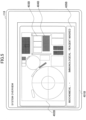
Fig. 4 is an example of a system overview screen showing that the first mechanisms cannot make an analysis. -
Fig. 5 is an example of a system overview screen showing that the second mechanisms cannot make an analysis. -
Fig. 6 is an example of a reagent overview screen. -
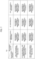
Fig. 7 is a matrix diagram that shows analysis mechanism statuses. - Embodiments of an automatic analyzer and an operation method for the automatic analyzer according to the present invention will be described with use of
FIG. 1 to FIG. 7 . - In the following embodiments, it goes without saying that constituent elements (including elementary steps and so forth) thereof are not necessarily indispensable except for the case in which an explicit statement is particularly made, the case in which the constituent element is obviously indispensable in principle, and so forth. Furthermore, in the drawings used in the present specification, the same or corresponding constituent elements are given the same or similar numerals and repeated description is omitted regarding these constituent elements in some cases.
- First, the overall configuration of an automatic analyzer will be described with use of
FIG. 1. FIG. 1 is a diagram schematically illustrating a plan view of the automatic analyzer. - In an
automatic analyzer 100 illustrated inFIG. 1 ,reaction vessels 111 line up on a circumference in an incubator (reaction disk) 101. Common vessels are used in all reactions as thereaction vessels 111 and thereaction vessels 111 are disposable. Theincubator 101 is controlled by a drive mechanism such as a motor in such a manner as to be rotationally driven by a distance equivalent to a length of predetermined number ofreaction vessels 111 in one cycle. - A plurality of reagent bottles and sample vessels can be placed on a circumference in a reagent/sample
common disk 102. In the present example, reagent bottles are located on the inner circumferential side of sample vessels. However, sample vessels may be located on the inner circumferential side of reagent bottles, or a configuration may be employed in which reagent bottles and sample vessels are located without division based on the inner circumferential side and the outer circumferential side. - In the present embodiment, in the reagent/sample
common disk 102, first reagents required only in analysis for a first analysis item group (biochemical items) and second reagents required only in analysis for a second analysis item group (immunological items) are housed together in one disk. - A
first dispensing mechanism 103 and asecond dispensing mechanism 104 that can rotate and vertically move are installed between theincubator 101 and the reagent/samplecommon disk 102, and each include a dispensing nozzle. Thefirst dispensing mechanism 103 and thesecond dispensing mechanism 104 are separately used in inspections in different analysis processes. When thefirst dispensing mechanism 103 is employed as a mechanism for biochemical inspection and thesecond dispensing mechanism 104 is employed as a mechanism for immunological inspection, the necessity to prevent contamination between samples is high in thesecond dispensing mechanism 104 for immunological inspection and therefore dispensing is performed with use of adisposable dispensing tip 110 in thesecond dispensing mechanism 104. - In the
first dispensing mechanism 103, a sample and a reagent for biochemical inspection are dispensed. In thesecond dispensing mechanism 104, a sample and a reagent for immunological inspection are dispensed. Regarding a sample for which measurement is performed for inspections of both biochemical inspection and immunological inspection, the dispensing mechanism makes access and performs dispensing in both thefirst dispensing mechanism 103 and thesecond dispensing mechanism 104. - The dispensing nozzle moves while drawing a circular arc around a rotation axis and performs sample dispensing from a sample vessel to a reaction vessel installed in the
incubator 101. On the trajectory of the dispensing nozzle, a sample aspiration position and a reagent aspiration position on the reagent/samplecommon disk 102, a first dispensing position and a second dispensing position on theincubator 101, and a cleaning tank for cleaning the dispensing nozzle exist. - For the
second dispensing mechanism 104, a dispensing tip mounting position and a dispensing tip discarding position also exist on the trajectory because the dispensingtip 110 is used. - The
first dispensing mechanism 103 and thesecond dispensing mechanism 104 are disposed in such a manner that physical interference does not occur between the trajectories of the respective dispensing nozzles and between the respective mechanisms. After a sample and a reagent are aspirated by the dispensing nozzle or the dispensing tip mounted on the dispensing nozzle, the sample and the reagent are stirred and mixed in a reaction vessel installed in theincubator 101, by aspiration-discharge operation of the dispensing nozzle or the dispensing tip. The reaction vessel that houses a reacted liquid resulting from the mixing of the sample and the reagent is managed at a predetermined temperature by theincubator 101 and reaction is promoted for a predetermined time. - A
reagent stirring mechanism 105 as stirring means is set around the reagent/samplecommon disk 102. Thisreagent stirring mechanism 105 moves to an area above the reagent vessel in which a magnetic particle solution that should be stirred is put, and lowers a magnetic particle stirring element of thereagent stirring mechanism 105 to stir the magnetic particle solution by rotating this stirring element. In order to keep magnetic particles in the solution from naturally precipitating, the magnetic particles are stirred immediately before the reagent is dispensed. - A
spectrophotometer 107 for biochemical inspection is disposed around theincubator 101. Thespectrophotometer 107 includes a light source and a detector (neither is omitted for convenience of illustration) and measures the absorbance of a reacted liquid resulting from mixing of a sample and a reagent, by dispersing and detecting transmitted light obtained through irradiating the reacted liquid with the light source. - Furthermore, the reacted liquid resulting from reaction for a predetermined time by the
incubator 101 can be brought to adetection mechanism 108 for immunological inspection by adetector syringe 106 and be measured. In the immunological inspection, there are systems in which electrochemiluminescence or chemiluminescence is employed as the principle as a system that detects a labeled substance. A secondliquid container 114, a labeled substance, and the structure and properties of a detection area suitable for each are selected, and the amount of luminescence that derives from luminescence reaction of the labeled substance is measured with use of a photomultiplier tube as the detector. - The reaction vessel about which measurement of the absorbance has been completed in the
incubator 101 is discarded into a dispensing tip/reactionvessel discarding box 112 by a dispensing tip/reactionvessel transporting mechanism 109. Movement of the reaction vessel in which the reacted liquid resulting from reaction for a predetermined time by theincubator 101 is put to thedetection mechanism 108 and movement of the reaction vessel about which measurement has been completed in thedetection mechanism 108 to the dispensing tip/reactionvessel discarding box 112 are also performed by the dispensing tip/reactionvessel transporting mechanism 109. - After completion of measurement, a cleaning
liquid container 115 is used in order to clean thefirst dispensing mechanism 103 or thesecond dispensing mechanism 104. - A
control part 116 is connected to pieces of equipment in the above-describedautomatic analyzer 100 and controls operation of the respective pieces of equipment and mechanisms in theautomatic analyzer 100, such as rotational driving of theincubator 101, rotational operation of the reagent/samplecommon disk 102, and operations of driving, sample aspiration, and sample discharge of a sample nozzle. InFIG. 1 , illustration is made with omission of the connection between the respective mechanisms that configure the automatic analyzer and thecontrol part 116 for simplification of illustration. - The
control part 116 is a computer including a CPU and.a memory, and performs computation processing to obtain the concentration of a predetermined component in a sample from a detection result of thespectrophotometer 107 or thedetection mechanism 108. - The control of the operation of the respective pieces of equipment by the
control part 116 is performed based on various programs recorded in a storage device. In the storage device, various.parameters input through an input device, information on a measurement-target sample (information by sample type, and so forth), measurement results, and so forth are stored besides various programs used for measurement of a sample. - A
storage part 117 is connected to thecontrol part 116, and stores information required to control theautomatic analyzer 100, the current situation of theautomatic analyzer 100, and so forth and affects operation of thecontrol part 116. - The control processing of operation performed in the
control part 116 may be marshaled into one program or the respective kinds of control processing may be separated into a plurality of programs, or the control processing may be a combination of them. Moreover, part or all of the programs may be implemented by dedicated hardware or may be modularized. - A
display part 118 is display equipment, such as a liquid crystal display, that displays, for an operator, an input screen of various parameters and setting, analysis inspection data of first inspection or re-inspection, a measurement result, and various kinds of information in theautomatic analyzer 100, such as reagent information. Thedisplay part 118 can be made into a touch panel system that doubles as an input part. - In
FIG. 1 , description has been made about the form in which reagents and samples are housed in one disk as the reagent/sample common disk. However, it is possible to employ a form in which samples are housed in different dedicated disks. In this case, as dispensing mechanisms, one or more dispensing mechanisms for exclusive use for reagent dispensing and one or more dispensing mechanisms for sample dispensing can be each disposed for exclusive use. - Furthermore, description will be made about the case in which, as analysis item groups, the first analysis item group is biochemical items and the second analysis item group is immunological items. However, the analysis item groups are not limited to this combination and other items such as an electrolyte and blood can be employed as another analysis item group.
-
FIG. 2 is a view illustrating a mechanism classification table 201 in which a classification of a first mechanism required only in analysis for the first analysis item group, a second mechanism required only in analysis for the second analysis item group, and a third mechanism required in both analysis for the first analysis item group and analysis for the second analysis item group is stored in theautomatic analyzer 100 illustrated inFIG. 1 . This table is stored in thestorage part 117. - As described above, the first analysis item group is biochemical items and the second analysis.item group is immunological items. Thus, the first mechanism is classified as a mechanism for biochemical items and the second mechanism is classified as a mechanism for immunological items.
- In this case, as illustrated in
FIG. 2 , afirst mechanism group 202 is configured by mechanisms used only in analysis for the first analysis item group and is formed from thefirst dispensing mechanism 103 and thespectrophotometer 107. Besides, for example, there are a syringe for thefirst dispensing mechanism 103 and so forth. - A
second mechanism group 203 is configured by mechanisms used only in analysis for the second analysis item group and is formed from thesecond dispensing mechanism 104, thedetector syringe 106, thedetection mechanism 108, the dispensingtip 110, and the secondliquid container 114. Besides, for example, there are a syringe for thesecond dispensing mechanism 104, system reagents, and a system reagent supply system. - A
common mechanism group 204 is configured by mechanisms used in analysis for both the first analysis item group and the second analysis item group and is formed from theincubator 101, the reagent/samplecommon disk 102, thereagent stirring mechanism 105, the dispensing tip/reactionvessel transporting mechanism 109, thereaction vessel 111, the dispensing tip/reactionvessel discarding box 112, awaste liquid tank 113, and the cleaningliquid container 115. Besides, for example, there are system water and a system water supply system. - These
first mechanism group 202,second mechanism group 203, andcommon mechanism group 204 are disposed in the casing of theautomatic analyzer 100. - With the classification made in this manner, the
control part 116 of the present embodiment activates thesecond mechanism group 203 and thecommon mechanism group 204 without activating thefirst mechanism group 202 when analysis for the biochemical items is not required, and activates thefirst mechanism group 202 and thecommon mechanism group 204 without activating thesecond mechanism group 203 when analysis for the immunological items is not required. - Furthermore, the
control part 116 activates only thesecond mechanism group 203 and thecommon mechanism group 204 when the first reagent for the biochemical item is not housed in the reagent/samplecommon disk 102, and activates only thefirst mechanism group 202 and thecommon mechanism group 204 when the second reagent for the immunological item is not housed in the reagent/samplecommon disk 102. - Moreover, the
control part 116 activates only thesecond mechanism group 203 and thecommon mechanism group 204 when it is decided that an abnormality has occurred in thefirst mechanism group 202, and activates only thefirst mechanism group 202 and thecommon mechanism group 204 when it is decided that an abnormality has occurred in thesecond mechanism group 203. - Subsequently, details of these kinds of control will be described with use of
FIG. 3A ,FIG. 3B , andFIG. 3C .FIG. 3A is a flowchart that sets the analysis mechanism status according to the installed reagent.FIG. 3B is a flowchart that sets the analysis mechanism status according to the mechanism status.FIG. 3C is a flowchart that decides which mechanism to be activated, according to the analysis mechanism status. -
FIG. 3A andFIG. 3B to be described below are flowcharts that flow at the time of reagent registration or at the time of occurrence of an abnormality. At the time of analysis request (FIG. 3C ), thecontrol part 116 may operate in the classification that has been already determined. - First,
FIG. 3A will be described. Thecontrol part 116 acquires all pieces of information on the reagents that have been installed in the reagent/samplecommon disk 102 and been registered, checks the acquired reagent information (step (hereinafter, described as "S") 302), and decides which status of "only biochemical reagent," "both biochemical reagent and immunological reagent," and "only immunological reagent" the installed reagents are in (S303). - When it is decided that the installed reagents are "only biochemical reagent," the
control part 116 sets the respective mechanism statuses to "analysis is possible" for thefirst mechanism group 202 and "analysis is impossible" for the second mechanism group 203 (S304). - Furthermore, when it is decided that the installed reagents are "both biochemical reagent and immunological reagent," the
control part 116 sets the respective mechanism statuses to "analysis is possible" for both thefirst mechanism group 202 and the second mechanism group 203 (S305). - Moreover, when it is decided that the installed reagents are "only immunological reagent," the
control part 116 sets the respective mechanism statuses to "analysis is impossible" for thefirst mechanism group 202 and "analysis is possible" for the second mechanism group 203 (S306). - After the mechanism statuses are determined, the mechanism statuses displayed on a system overview screen like ones illustrated in
FIG. 4 andFIG. 5 , for example, are updated (S322). - Next,
FIG. 3B will be described. The flow ofFIG. 3B may be performed after the flow ofFIG. 3A continuously or may be performed at a different timing from it. Thecontrol part 116 acquires all pieces of information on the status of thefirst mechanism group 202, thesecond mechanism group 203, and the common mechanism group 204 (S307), and decides which of "abnormality exists only infirst mechanism group 202," "abnormality exists only insecond mechanism group 203," and "mechanism abnormality does not exist" the status of thefirst mechanism group 202 and thesecond mechanism group 203 is (S308). - For example, in the
second mechanism group 203, a performance check of thedetection mechanism 108 is performed at the time of analysis preparation operation and, when an abnormality exists in the temperature, a signal value, or the like, thecontrol part 116 sets the status of thesecond mechanism group 203 to the status in which analysis is impossible (S309). Furthermore, thecontrol part 116 sets the status of thesecond mechanism group 203 to the status in which analysis is impossible also when a pressure abnormality or sensor abnormality is sensed in thesecond dispensing mechanism 104 or thedetector syringe 106. Besides, also when insufficiency of the capacity of the dispensingtip 110 or the secondliquid container 114 has occurred, the status of thesecond mechanism group 203 is set to the status in which analysis is impossible (S309). In these occasions, thecontrol part 116 sets thefirst mechanism group 202 to "analysis is possible." - Moreover, when an abnormality has occurred in neither mechanism, the status of the
first mechanism group 202 and the status of thesecond mechanism group 203 are set to the status in which analysis is possible (S310). - On the other hand, for example, in the
first mechanism group 202, a performance check of thespectrophotometer 107 is performed at the time of analysis preparation operation and, when an abnormality exists in the temperature, a signal value, or the like, thecontrol part 116 sets the status of thefirst mechanism group 202 to the status in which analysis is impossible (S311). Furthermore, also when a pressure abnormality or sensor abnormality is sensed in thefirst dispensing mechanism 103, thecontrol part 116 sets the status of thefirst mechanism group 202 to the status in which analysis is impossible (S311). In these occasions, thecontrol part 116 sets thesecond mechanism group 203 to "analysis is possible." - After the mechanism statuses are determined, the mechanism statuses displayed on the system overview screen like those illustrated in
FIG. 4 andFIG. 5 , for example, are updated (S323). - At this time, "analysis is impossible" decided in the check of the mechanism status (S308) and "analysis is impossible" decided in the check of the.installed.and registered reagents S303) are discriminated from each other. In the case of "analysis is impossible" based on the former, for example, "mechanism masked" is displayed on the system overview screen. In the case of "analysis is impossible" based on the latter, "reagent masked" is displayed. When the situation applies to both, "mechanism masked" is preferentially displayed. An example in which "mechanism masked" is displayed is illustrated in
FIG. 4 . An example in which "reagent masked" is displayed is illustrated inFIG. 5 . - Next,
FIG. 3C will be described. The flow ofFIG. 3C may be performed after the flow ofFIG. 3B continuously or may be performed at a different timing from it. Thecontrol part 116 checks the analysis possibility/impossibility status and decides which of "analysis is possible" and "analysis is impossible" thefirst mechanism group 202 and thesecond mechanism group 203 are set to (S312). - When it is decided that "analysis is possible" regarding the
first mechanism group 202 and "analysis is impossible" regarding thesecond mechanism group 203, thecontrol part 116 performs the analysis preparation operation only in the biochemical measuring system (first mechanism group 202 + common mechanism group 204) (S313), performs analysis operation only in the biochemical measuring system (S314), and performs analysis end operation only in the biochemical measurement system (S315) to end the operation. - Furthermore, when it is decided that "analysis is possible" regarding both the
first mechanism group 202 and thesecond mechanism group 203, thecontrol part 116 performs the analysis preparation operation in the biochemical and immunological measuring systems (first mechanism group 202 +second mechanism group 203 + common mechanism group 204) (S316), performs the analysis operation in the biobiochemical and immunological measuring systems (S317), and performs the analysis end operation in the biochemical and immunological measuring systems (S318) to end the operation. - Moreover, when it is decided that "analysis is impossible" regarding the
first mechanism group 202 and "analysis is possible" regarding thesecond mechanism group 203, thecontrol part 116 performs the analysis preparation operation only in the immunological measuring system (second mechanism group 203 + common mechanism group 204) (S319), performs the analysis operation only in the immunological measuring system (S320), and performs the analysis end operation only in the immunological measurement system (S321) to end the operation. - When an abnormality has occurred in the first mechanism group or the second mechanism group in the middle of performing of the analysis operation, the first mechanism group or the second mechanism group is recognized as the status in which analysis is impossible. Analysis items to be measured by the mechanism that has become the status in which analysis is impossible are skipped and analysis is continued regarding analysis items to be measured by the mechanism that is still capable of analysis. Stop of the analysis can be avoided as much as possible and measurement of measurable items can be continued.
- The analysis possibility/impossibility status is acquired from a matrix diagram illustrated in
FIG. 7 . The analysis possibility/impossibility status is determined from both statuses of the mechanism status and the registered reagent status. The mechanism status is acquired by the flow ofFIG. 3B and the registered reagent status is acquired by the flow ofFIG. 3A . Thecontrol part 116 obeys the respective statuses at the timing of operation. - When it is decided that a biochemical or immunological reagent is not installed based on the information on the installed reagents or when the biochemical or immunological mechanism is incapable of analysis due to the occurrence status of trouble with the mechanism, analysis for the corresponding analysis item group is unnecessary (impossible), and therefore the corresponding mechanism group is masked. Due to this, performing of the analysis preparation operation and the analysis end operation that are unnecessary is avoided and it becomes possible to decrease waiting time for the user and reduce also running costs due to generated water, power, and so forth.
- Only either one of the processing of the check of the registered reagents (S302 to S306) and the processing of the check of the mechanism status (S307 to S311) may be performed.
- Subsequently, description will be made with use of
FIG. 4 to FIG. 6 regarding details of a display screen suitably displayed by thedisplay part 118 in order to check the status of thefirst mechanism group 202, thesecond mechanism group 203, and thecommon mechanism group 204.FIG. 4 andFIG. 5 are examples of the system overview screen of the automatic analyzer.FIG. 6 is an example of a reagent overview screen of the automatic analyzer. - It is desirable that the timing when the screen of
FIG. 4 to FIG. 6 is displayed is set to a timing after S309, S310, or S311 inFIG. 3B and timings before and after S312. However, the timing is not limited thereto. - Preferably, after S309, S310, or S311 in
FIG. 3B and timings before and after S312, thecontrol part 116 causes thedisplay part 118 to display asystem overview screen 401A showing whether or not to activate thefirst mechanism group 202 or asystem overview screen 401B showing whether or not to activate thesecond mechanism group 203. - In the
system overview screen 401A illustrated inFIG. 4 and thesystem overview screen 401B illustrated inFIG. 5 ,mechanism view screens mechanisms mechanisms mechanisms mechanisms mechanisms mechanisms - The system status of the
first mechanism group 202 and thesecond mechanism group 203 is displayed in the respective mechanismstatus display screens - Moreover, the
control part 116 can cause thedisplay part 118 to display areagent overview screen 501 to check whether the first reagent and the second reagent have been installed in the reagent/samplecommon disk 102 or not, preferably during the flow ofFIG. 3A and the flow ofFIG. 3B . - In the
reagent overview screen 501 illustrated inFIG. 6 , alist screen 502 of reagent bottles installed in the reagent/samplecommon disk 102 and areagent bottle status 503 are displayed. - Furthermore, in the reagent
bottle list screen 502, which analysis item of the biochemical item and the immunological item the installed reagent bottle is to be used for is displayed. - Similarly, also in the
reagent bottle status 503, which of a biochemicalitem reagent bottle 503a (first reagent), an immuno-biochemicalitem reagent bottle 503b (second reagent), and aposition 503c without an installed reagent bottle the installed reagent bottle corresponds to is displayed in such a manner as to be understood at a glance. - Next, effects of the present embodiment will be described.
- The
automatic analyzer 100 of the above-described present embodiment includes thefirst mechanism group 202 used only in analysis for the biochemical items, thesecond mechanism group 203 used only in analysis for the immunological items, thecommon mechanism group 204 used in analysis for both the biochemical items and the immunological items, and thecontrol part 116 that activates thesecond mechanism group 203 and thecommon mechanism group 204 without activating thefirst mechanism group 202 when analysis for the biochemical items is not required, and activates thefirst mechanism group 202 and thecommon mechanism group 204 without activating thesecond mechanism group 203 when analysis for the immunological items is not required. - Due to this, in the composite-type
automatic analyzer 100 that can measure a plurality of analysis item groups by one device, even when a request is made regarding only one analysis item group, waiting time for the user caused for waiting for the end of the analysis preparation operation of the other analysis mechanism that does not perform measurement can be decreased and running costs due to water, power, and so forth generated for performing the analysis preparation operation of the other analysis mechanism that does not perform measurement can also be reduced. In addition, using unnecessary consumables for performing the analysis preparation operation of the other analysis mechanism that does not perform measurement is avoided. - Furthermore, the
control part 116 activates only thesecond mechanism group 203 and thecommon mechanism group 204 when the first reagent is not housed in the reagent/samplecommon disk 102, and activates only thefirst mechanism group 202 and thecommon mechanism group 204 when the second reagent is not housed in the reagent/samplecommon disk 102. Therefore, the need to wait for the end of the analysis preparation operation of the other analysis mechanism incapable of measurement is eliminated and it becomes possible to intend reduction in waiting time and reduction in running costs more surely. - Moreover, the
control part 116 activates only thesecond mechanism group 203 and thecommon mechanism group 204 when it is decided that an abnormality has occurred in thefirst mechanism group 202, and activates only thefirst mechanism group 202 and thecommon mechanism group 204 when it is decided that an abnormality has occurred in thesecond mechanism group 203. This also eliminates the need to wait for the end of the analysis preparation operation of the other analysis mechanism incapable of measurement and reduction in waiting time and reduction in running costs can be intended more surely. - Furthermore, the
automatic analyzer 100 further includes thedisplay part 118 that generates various displays for the operator of the automatic analyzer, and thecontrol part 116 causes thedisplay part 118 to display thesystem overview screen first mechanism group 202 or whether or not to activate thesecond mechanism group 203. Due to this, which mechanism involves trouble that makes analysis impossible can be rapidly understood and thus coping can be rapidly performed. Therefore, reduction in the total time required until analysis completion can be achieved. - Moreover, the
automatic analyzer 100 further includes thedisplay part 118 that generates various displays for the operator of the automatic analyzer, and thecontrol part 116 causes display of thereagent overview screen 501 to check whether the first reagent and the second reagent have been installed in the reagent/samplecommon disk 102. This allows discrimination of whether the installed reagents are "only biochemical reagent," "both biochemical reagent and immunological reagent," or "only immunological reagent," and it becomes easier to perform such coping as reagent input according to need. - The present invention is not limited to the above-described embodiment and allows various modifications and applications. The above-described embodiment is described in detail in order to explain the present invention in an easy-to-understand manner and is not necessarily limited to that including all configurations described.
-
- 100 automatic analyzer
- 101 incubator (third mechanism)
- 102 reagent/specimen common disk (housing part, third mechanism)
- 103: first dispensing mechanism (first mechanism)
- 104: second dispensing mechanism (second mechanism)
- 105: reagent stirring mechanism (third mechanism)
- 106: detector syringe (second mechanism)
- 107: spectrophotometer (first mechanism)
- 108: detection mechanism (second mechanism)
- 109: dispensing tip/reaction vessel transporting mechanism (third mechanism)
- 110: dispensing tip (second mechanism)
- 111: reaction vessel (third mechanism)
- 112: dispensing tip/reaction vessel discarding box (third mechanism)
- 113: waste liquid tank (third mechanism)
- 114: second liquid container (second mechanism)
- 115: cleaning liquid container
- 116: control part
- 117: storage part
- 118: display part
- 201: mechanism classification table
- 202: first mechanism group (first mechanisms)
- 203: second mechanism group (second mechanisms)
- 204: common mechanism group (third mechanisms)
- 401A, 401B: system overview screen
- 402A, 402B: mechanism view screen
- 403A, 403B: mechanism capable of analysis
- 404A, 404B: mechanism incapable of analysis
- 405A, 405B: mechanism status display screen
- 501: reagent overview screen
- 502: reagent bottle list screen
- 503: reagent bottle status
- 503a: biochemical item reagent bottle (first reagent)
- 503b: immuno-biochemical item reagent bottle (second reagent)
- 503c: position without an installed reagent bottle
Claims (8)
- An automatic analyzer comprising:a first mechanism that is used only in analysis for a first analysis item group;a second mechanism that is used only in analysis for a second analysis item group;a third mechanism that includes a housing part to house a first reagent required only in analysis for the first analysis item group and a second reagent required only in analysis for the second analysis item group and is used in analysis for both the first analysis item group and the second analysis item group; anda control part that controls the first mechanism, the second mechanism, and the third mechanism so that when analysis for the first analysis item group is not required, the second mechanism and the third mechanism are activated without activating the first mechanism, and when analysis for the second analysis item group is not required, the first mechanism and the third mechanism are activated without activating the second mechanism.
- The automatic analyzer according to Claim 1, whereinthe control partactivates only the second mechanism and the third mechanism when the first reagent is not housed in the housing part, andactivates only the first mechanism and the third mechanism when the second reagent is not housed in the housing part.
- The automatic analyzer according to Claim 1, whereinthe control partactivates only the second mechanism and the third mechanism when it is decided that an abnormality has occurred in the first mechanism, andactivates only the first mechanism and the third mechanism when it is decided that an abnormality has occurred in the second mechanism.
- The automatic analyzer according to Claim 1, whereinthe first analysis item group is biochemical items, andthe second analysis item group is immunological items.
- The automatic analyzer according to Claim 1, further comprising:a display part that generates various displays for an operator of the automatic analyzer, whereinthe control part causes the display part to display a screen showing whether or not to activate the first mechanism or whether or not to activate the second mechanism.
- The automatic analyzer according to Claim 1, further comprising:a display part that generates various displays for an operator of the automatic analyzer, whereinthe control part causes display of a screen to check whether the first reagent and the second reagent have been installed in the housing part or not.
- The automatic analyzer according to Claim 1, wherein
the first mechanism, the second mechanism, and the third mechanism are placed in a casing. - An operation method for an automatic analyzer comprising: a first mechanism that is used only in analysis for a first analysis item group; a second mechanism that is used only in analysis for a second analysis item group; a third mechanism that includes a housing part to house a first reagent required only in analysis for the first analysis item group and a second reagent required only in analysis for the second analysis item group and is used in analysis for both the first analysis item group and the second analysis item group, whereinwhen analysis for the first analysis item group is not required, only the second mechanism and the third mechanism are activated without activating-the first mechanism, andwhen analysis for the second analysis item group is not required, only the first mechanism and the third mechanism are activated without activating the second, mechanism.
Applications Claiming Priority (2)
| Application Number | Priority Date | Filing Date | Title |
|---|---|---|---|
| JP2021145051 | 2021-09-06 | ||
| PCT/JP2022/030211 WO2023032601A1 (en) | 2021-09-06 | 2022-08-08 | Automatic analysis device and method for operating automatic analysis device |
Publications (2)
| Publication Number | Publication Date |
|---|---|
| EP4400842A1 true EP4400842A1 (en) | 2024-07-17 |
| EP4400842A4 EP4400842A4 (en) | 2025-07-23 |
Family
ID=85412199
Family Applications (1)
| Application Number | Title | Priority Date | Filing Date |
|---|---|---|---|
| EP22864187.4A Pending EP4400842A4 (en) | 2021-09-06 | 2022-08-08 | AUTOMATIC ANALYSIS DEVICE AND METHOD FOR OPERATING AN AUTOMATIC ANALYSIS DEVICE |
Country Status (5)
| Country | Link |
|---|---|
| US (1) | US20240369585A1 (en) |
| EP (1) | EP4400842A4 (en) |
| JP (1) | JPWO2023032601A1 (en) |
| CN (1) | CN117836633A (en) |
| WO (1) | WO2023032601A1 (en) |
Family Cites Families (11)
| Publication number | Priority date | Publication date | Assignee | Title |
|---|---|---|---|---|
| JPS63229371A (en) * | 1987-03-19 | 1988-09-26 | Nittec Co Ltd | Automatic analyzer |
| WO1996012968A1 (en) * | 1994-10-19 | 1996-05-02 | Japan Tectron Instruments Corporation | Automatic analyzer |
| JP2002048802A (en) * | 2000-08-07 | 2002-02-15 | Hitachi Ltd | Automatic analysis system |
| JP3990945B2 (en) * | 2002-06-28 | 2007-10-17 | 株式会社日立ハイテクノロジーズ | Automatic analyzer |
| JP2011027636A (en) * | 2009-07-28 | 2011-02-10 | Beckman Coulter Inc | Analysis system and reagent container supply method |
| JP6266327B2 (en) * | 2013-12-09 | 2018-01-24 | 東芝メディカルシステムズ株式会社 | Automatic analyzer |
| JP6247935B2 (en) | 2014-01-07 | 2017-12-13 | 株式会社日立ハイテクノロジーズ | Automatic analyzer |
| JP7053310B2 (en) * | 2018-02-28 | 2022-04-12 | シスメックス株式会社 | Specimen measuring device, power supply cutoff method |
| CN113490853B (en) * | 2019-03-01 | 2023-10-03 | 株式会社日立高新技术 | automatic analysis device |
| WO2020217636A1 (en) * | 2019-04-26 | 2020-10-29 | 株式会社日立ハイテク | Automatic analysis device |
| MX2022003519A (en) * | 2019-10-09 | 2022-04-25 | Hitachi High Tech Corp | AUTOMATIC ANALYZER. |
-
2022
- 2022-08-08 WO PCT/JP2022/030211 patent/WO2023032601A1/en not_active Ceased
- 2022-08-08 CN CN202280056525.XA patent/CN117836633A/en active Pending
- 2022-08-08 JP JP2023545391A patent/JPWO2023032601A1/ja active Pending
- 2022-08-08 EP EP22864187.4A patent/EP4400842A4/en active Pending
- 2022-08-08 US US18/683,965 patent/US20240369585A1/en active Pending
Also Published As
| Publication number | Publication date |
|---|---|
| US20240369585A1 (en) | 2024-11-07 |
| CN117836633A (en) | 2024-04-05 |
| WO2023032601A1 (en) | 2023-03-09 |
| JPWO2023032601A1 (en) | 2023-03-09 |
| EP4400842A4 (en) | 2025-07-23 |
Similar Documents
| Publication | Publication Date | Title |
|---|---|---|
| US5270211A (en) | Sample tube entry port for a chemical analyzer | |
| JP3990944B2 (en) | Automatic analyzer | |
| US7185288B2 (en) | Operator interface module segmented by function in an automatic clinical analyzer | |
| US9513302B2 (en) | Reagent transfer device | |
| EP1293781B1 (en) | Transfer unit and automatic analyzing apparatus having such transfer unit | |
| JP4866808B2 (en) | Automatic analyzer | |
| EP2293083A1 (en) | Automatic analyzer | |
| US11965903B2 (en) | Automated analyzer and method of controlling automated analyzer | |
| CN1826218B (en) | Automated Multi-Detector Analyzer | |
| EP2019321A1 (en) | Cleaning equipment and automatic analyzer | |
| WO2014077219A1 (en) | Automated analyzer | |
| US20220341956A1 (en) | Automatic analyzer | |
| CN1800857A (en) | Automatic analyzer | |
| JP2008003010A (en) | Autoanalyzer | |
| JP6429753B2 (en) | Automatic analyzer and automatic analysis method | |
| JP7329625B2 (en) | Automatic analyzer, display system for automatic analyzer, and display method for automatic analyzer | |
| JP7494374B2 (en) | AUTOMATIC ANALYZER AND METHOD FOR CONTROLLING AUTOMATIC ANALYZER | |
| US20240369585A1 (en) | Automatic analyzer and operation method for automatic analyzer | |
| US12111327B2 (en) | Automatic analyzer with a control unit for displaying background maintenance operation notifications | |
| EP3992634A1 (en) | Automatic analysis device | |
| EP3640647B1 (en) | Automated analysis device | |
| EP3961224B1 (en) | Automatic analysis device | |
| EP4471428A1 (en) | Automatic analysis device and automatic analysis method | |
| JP2024082548A (en) | Transport rack, automatic analyzer, and automatic analysis system | |
| JP7685061B2 (en) | automatic analyzer |
Legal Events
| Date | Code | Title | Description |
|---|---|---|---|
| STAA | Information on the status of an ep patent application or granted ep patent |
Free format text: STATUS: THE INTERNATIONAL PUBLICATION HAS BEEN MADE |
|
| PUAI | Public reference made under article 153(3) epc to a published international application that has entered the european phase |
Free format text: ORIGINAL CODE: 0009012 |
|
| STAA | Information on the status of an ep patent application or granted ep patent |
Free format text: STATUS: REQUEST FOR EXAMINATION WAS MADE |
|
| 17P | Request for examination filed |
Effective date: 20240321 |
|
| AK | Designated contracting states |
Kind code of ref document: A1 Designated state(s): AL AT BE BG CH CY CZ DE DK EE ES FI FR GB GR HR HU IE IS IT LI LT LU LV MC MK MT NL NO PL PT RO RS SE SI SK SM TR |
|
| DAV | Request for validation of the european patent (deleted) | ||
| DAX | Request for extension of the european patent (deleted) | ||
| A4 | Supplementary search report drawn up and despatched |
Effective date: 20250623 |
|
| RIC1 | Information provided on ipc code assigned before grant |
Ipc: G01N 35/00 20060101AFI20250616BHEP Ipc: G01N 35/02 20060101ALI20250616BHEP |
|
| STAA | Information on the status of an ep patent application or granted ep patent |
Free format text: STATUS: EXAMINATION IS IN PROGRESS |
|
| 17Q | First examination report despatched |
Effective date: 20260527 |
|
| RAP3 | Party data changed (applicant data changed or rights of an application transferred) |
Owner name: HITACHI HIGH-TECH CORPORATION Owner name: F. HOFFMANN-LA ROCHE AG Owner name: ROCHE DIAGNOSTICS GMBH |