EP4400838A1 - Flowcell device, flowcell control system and method - Google Patents
Flowcell device, flowcell control system and method Download PDFInfo
- Publication number
- EP4400838A1 EP4400838A1 EP23151826.7A EP23151826A EP4400838A1 EP 4400838 A1 EP4400838 A1 EP 4400838A1 EP 23151826 A EP23151826 A EP 23151826A EP 4400838 A1 EP4400838 A1 EP 4400838A1
- Authority
- EP
- European Patent Office
- Prior art keywords
- motor
- flowcell
- flow rate
- flowcell device
- sensor
- Prior art date
- Legal status (The legal status is an assumption and is not a legal conclusion. Google has not performed a legal analysis and makes no representation as to the accuracy of the status listed.)
- Pending
Links
Images


Classifications
-
- G—PHYSICS
- G01—MEASURING; TESTING
- G01N—INVESTIGATING OR ANALYSING MATERIALS BY DETERMINING THEIR CHEMICAL OR PHYSICAL PROPERTIES
- G01N27/00—Investigating or analysing materials by the use of electric, electrochemical, or magnetic means
- G01N27/26—Investigating or analysing materials by the use of electric, electrochemical, or magnetic means by investigating electrochemical variables; by using electrolysis or electrophoresis
- G01N27/28—Electrolytic cell components
- G01N27/30—Electrodes, e.g. test electrodes; Half-cells
- G01N27/333—Ion-selective electrodes or membranes
-
- G—PHYSICS
- G01—MEASURING; TESTING
- G01N—INVESTIGATING OR ANALYSING MATERIALS BY DETERMINING THEIR CHEMICAL OR PHYSICAL PROPERTIES
- G01N15/00—Investigating characteristics of particles; Investigating permeability, pore-volume or surface-area of porous materials
- G01N15/10—Investigating individual particles
- G01N15/14—Optical investigation techniques, e.g. flow cytometry
- G01N15/1434—Optical arrangements
- G01N15/1436—Optical arrangements the optical arrangement forming an integrated apparatus with the sample container, e.g. a flow cell
-
- G—PHYSICS
- G01—MEASURING; TESTING
- G01N—INVESTIGATING OR ANALYSING MATERIALS BY DETERMINING THEIR CHEMICAL OR PHYSICAL PROPERTIES
- G01N27/00—Investigating or analysing materials by the use of electric, electrochemical, or magnetic means
- G01N27/26—Investigating or analysing materials by the use of electric, electrochemical, or magnetic means by investigating electrochemical variables; by using electrolysis or electrophoresis
- G01N27/416—Systems
-
- G—PHYSICS
- G01—MEASURING; TESTING
- G01N—INVESTIGATING OR ANALYSING MATERIALS BY DETERMINING THEIR CHEMICAL OR PHYSICAL PROPERTIES
- G01N27/00—Investigating or analysing materials by the use of electric, electrochemical, or magnetic means
- G01N27/02—Investigating or analysing materials by the use of electric, electrochemical, or magnetic means by investigating impedance
- G01N27/04—Investigating or analysing materials by the use of electric, electrochemical, or magnetic means by investigating impedance by investigating resistance
- G01N27/06—Investigating or analysing materials by the use of electric, electrochemical, or magnetic means by investigating impedance by investigating resistance of a liquid
- G01N27/08—Investigating or analysing materials by the use of electric, electrochemical, or magnetic means by investigating impedance by investigating resistance of a liquid which is flowing continuously
- G01N27/10—Investigation or analysis specially adapted for controlling or monitoring operations or for signalling
-
- G—PHYSICS
- G01—MEASURING; TESTING
- G01N—INVESTIGATING OR ANALYSING MATERIALS BY DETERMINING THEIR CHEMICAL OR PHYSICAL PROPERTIES
- G01N33/00—Investigating or analysing materials by specific methods not covered by groups G01N1/00 - G01N31/00
- G01N33/18—Water
- G01N33/1893—Water using flow cells
Definitions
- the invention relates to a flowcell device for sensing electrochemical process parameters, a flowcell control system, a method for sensing electrochemical process parameters in a flowcell device, and a usage of a motor in a flowcell device.
- the sensor consumes chlorine ions.
- the consumption of chlorine ions is offset by the constant replacement of ions due to the flowrate.
- the ions will not get replaced quickly enough. This will form a layer near the membrane surface with a lower concentration of chlorine, and the reading will drop towards zero.
- the described embodiments similarly pertain to the flowcell device, the flowcell control system, the method for sensing electrochemical process parameters in a flowcell device, and the usage of a stirrer in a flowcell device. Synergetic effects may arise from different combinations of the embodiments although they might not be described in detail.
- a flowcell device for sensing electrochemical process parameters.
- the flowcell comprises a cell housing, a sensor housing for receiving a sensor, arranged at a side, e.g. an end side, of the cell housing and protruding into the cell housing; and a motor arrangement arranged at the cell housing for stirring the liquid when the flowcell is in operation.
- the electrochemical process parameters can include, for example, a concentration of molecules or ions such as chlorine ions.
- the sensor housing may be a housing integrated into the flowcell device where the sensor may be inserted later. Alternatively, the housing contains the sensor already when assembling the flowcell device.
- the sensor may comprise a sensor circuit that may receive sensed sensor signals and convert them into an analog signal or digital data to be communicated to, for example, a server or generally into a network, or which may be communicated to a motor controller that controls the motor, as described in embodiments below.
- the motor arrangement comprises a first portion inside a motor housing such that the first portion does not contact a liquid, a second portion outside the motor housing, and a motor.
- the motor is configured to drive the first portion of the motor arrangement, the first portion is configured to drive the second portion of the motor arrangement, and the second portion is configured to stir the liquid when the flowcell device is in operation.
- the motor arrangement comprises a motor for driving a first portion of the motor arrangement, the first portion being not in contact with the liquid for driving a second portion of the motor arrangement, and the second portion being in contact with the liquid for stirring the liquid when the flowcell is in operation.
- the motor arrangement is also referred to as stirrer in this disclosure.
- the two portions of the motor arrangement effect that the stirring takes place such that the motor does not get in contact with the liquid.
- the first and the second portions are in physical interaction with each other, such that the second portion, which is responsible for stirring the liquid, rotates with the first portion, which is driven directly by the motor.
- the first portion of the motor arrangement comprises magnets
- the second portion of the motor arrangement comprises a magnetically effective stirrer bar, wherein the motor is configured to rotate the magnets and the magnets are configured to rotate the magnetic stirrer bar.
- the motor is for example a brushless DC motor in order to ensure a required lifetime.
- Magneticically effective means that the stirrer bar is made of magnetic material experiencing magnetic forces or being itself a permanent magnet.
- the second portion consists only of the stirrer bar.
- the second portion consists additionally of a fixing mechanism such as a pin around which the stirrer bar rotates or a rotatable disk on which the stirrer bar is mounted.
- the geometrical shape of the stirrer bar may be cuboid, but may in principal have any shape that is suitable to stir the liquid and being rotated in the magnetic field of the magnets.
- the shape instead of a bar-shape, the shape may be rotor-wing-like.
- the first and the second portions of the motor arrangement are water-tightly separated from each other.
- the first and the second portions are water-tightly separated from each other, so that there is no leak path into the motor.
- the first portion is enclosed in a housing that protrudes at the bottom of the flowcell housing into the flowcell and which is coupled in a water-tight way to the housing of the second portion.
- the housing of the first portion may be made of one integral piece at least in the area, where it protrudes into the flowcell.
- it may comprise a lid or a cover, which can be fastened at the top of the housing in a water-tight way.
- the cover may comprise a thread and/or a seal.
- the flowcell device further comprises the sensor, and the sensor again comprises a membrane.
- the sensor is configured to sense a chemical substance inside the cell housing, more exactly inside a pipe within the cell housing, at the membrane thereby consuming a part of the chemical substance, and the second portion of the motor arrangement is configured to stir a solution comprising the chemical substance.
- the membrane is, for example, a diffusion membrane based on electrochemical measurements, which is designed to be conductive as a measuring electrode.
- the functionality of the sensor thus may comprise consuming the chemical substance, for example molecules or ions such as chlorine ions, at the membrane as the reaction takes place. Conventionally, if the flow drops too low, then the ions will not get replaced quickly enough. This will form a layer near the membrane surface of the sensor with a lower concentration of chlorine, and the reading will drop towards zero. If the stirrer is turned on, then this will agitate the sample, i.e., the liquid, around the membrane surface, and stop this layer of lower concentration from forming. This means that the sensor can operate at a significantly lower flowrate.
- the device therefore ensures a significantly improved measurement quality or prevents incorrect measurements at changing or low flow rates. In these cases a concentration gradient near the membrane is avoided and the concentration is detected correctly.
- the flowcell device further comprises a pipe configured to receive a fluid from an inlet of the flowcell device and to direct the liquid to an outlet of the flowcell device.
- the membrane is disposed on a side of the sensor facing the motor arrangement. The sensor protrudes sufficiently from the sensor housing into the pipe toward the motor arrangement to leave only a gap between the stirrer bar and the membrane.
- a “gap” means that the distance and hence the space or volume between the stirrer bar and the membrane is small. For example, the distance is in the same order of size as the diameter of the inlet. By minimizing this volume, the speed of response of the sensor is increased significantly.
- the gap may be realized for example by dimensioning the size, i.e., length of the sensor, or the size or length of the sensor housing, by the location of the motor arrangement, in particular the stirrer bar, which may be for example near the inlet, or by dimensioning the size of the flowcell device itself.
- the flowcell device further comprises a transmitter, and the sensor and the motor are powered from the transmitter.
- a signal from a transmitter switches on the sensor and the motor at the same time.
- the motor may then remain in a switched-on state until a signal from a transmitter indicates switching off the sensor and the motor.
- the flowcell device further comprises a flow control unit configured to determine a flow rate of the liquid running through the housing of the flowcell device, and the flowcell device further comprises a motor controller configured to control the motor according to the determined flow rate of the liquid.
- the flow rate is controlled by the flow control unit. That is, the flow control unit having information about the flow rate of the liquid, communicates the flow rate to the controller that controls the motor, which is also referred to as motor controller in the following.
- the motor controller then switches the motor on and off in dependence on the flow rate. As an example, the controller switches on the motor if the flow rate falls below a pre-determined threshold. The same threshold or a different threshold may be used for switching off the motor if the flow rate exceeds this threshold.
- the motor controller may control the motor in dependence on the rate of change of the concentration.
- the control unit is configured to provide a control signal for controlling the motor in dependence on the determined flow rate of the liquid.
- the motor may be switched on as soon as the concentration drops.
- pre-determined thresholds and observation time intervals in which the drop of concentration is to be detected may be applied.
- the rotation speed may be adapted to the flow rate of the liquid through the flowcell.
- the described options may be mixed. For example, conditions may be determined and different thresholds may be applied at which the motor is stopped or switched on and at which the rotation speed is adapted. Conditions may, for example be a concentration or the rate of change of the concentration as described above.
- the motor controller activates the motor in time intervals.
- the time intervals may be regular, pre-determined time intervals or may be dependent on the flow rate or change rate of the concentration or other criteria.
- the motor and the first portion are a modular unit attachable to the housing of the flowcell device.
- the first portion and the second portion may be designed in a modular way, such that, for example, the motor can be easily exchanged, upgraded, etc.
- the motor controller can be exchanged to have a microprocessor, the software may be updated, or there may be modules with different types of motors, etc.
- a usage of a stirrer in a flowcell device for stirring a liquid inside the housing of the flowcell device is provided.
- the stirrer consists of a motor arrangement as described herein.
- the motor drives a stirrer bar and is arranged at the housing of the flowcell.
- the transmission of the rotation of the motor and the stirrer bar is realized using magnetic forces.
- a flowcell control system for a flowcell device.
- the flowcell control system comprises a motor, a motor controller and a flow control unit.
- the flow control unit is configured to control a flow rate of a liquid in the flowcell and to send a flow rate value of the flow rate to a motor controller.
- the motor controller is configured to receive the flow rate value and to control a motor for stirring the liquid, and the motor configured to be controlled by the motor controller.
- the flowcell control system comprises the electrical components of the flowcell device, especially control means with respect to the stirring such as the flow control unit and the motor controller, and the motor to be controlled.
- the flowcell control system may further comprise communication means, for example, for communicating the flow rate and control signals.
- the flowcell control system further comprises a sensor circuit configured to detect an electrochemical process parameter sensed by a sensor of the flowcell device, wherein the sensor circuit is configured to send an electrochemical process parameter value to the motor controller, and wherein the motor controller is configured to control the motor using the electrochemical process parameter value.
- the sensor circuit may be part of the sensor or a separate processing unit.
- the sensor circuit is the electronic part of that converts the sensing into analog signals and/or digital output signals and which represents the interface to further data or signal processing devices, such as network devices, clients or servers, or it may be itself a human machine interface.
- a method for sensing electrochemical process parameters in a flowcell device comprising the following steps.
- a flow rate of a liquid in the flowcell device is controlled by a flow control unit.
- a flow rate value of the flow rate is sent to a motor controller by the flow control unit.
- the flow rate value is received by a motor controller and in a fourth step, the motor is controlled for stirring the liquid in dependence on the flow rate value by the motor controller.
- the step controlling the motor for stirring the liquid in dependence on the flow rate comprises comparing the flow rate value with a pre-defined threshold and switching on the motor if the threshold is exceeded, and switching off the motor if the threshold falls below the threshold.
- the rotation speed may be controlled.
- the communication between the control unit and the motor controller for providing the flow rate may be realized by a wired connection, over which an analog or digital signal is transmitted to the motor controller. Alternatively, the communication takes place over a wireless connection to any known communication standard, especially a short range communication standard.
- the control of the motor is realized in any suitable way known to a skilled person. E.g. the control is performed using analog and/or digital circuits and by providing a control current or control voltage to the motor.
- the digital circuits may include logic elements or logic devices, programmable devices such as a CPLD, an FPGA, a microprocessor, etc.
- the motor controller may include memory devices to accommodate software or data, and/or to log the control actions.
- Fig. 1 shows a sketch of a flowcell device 100 for sensing electrochemical process parameters.
- the flowcell device 100 comprises a cell housing 102, a sensor housing 104 for receiving a sensor 150, arranged at a top side of the cell housing 102 and protruding into the cell housing 102.
- the liquid flow enters the flowcell device 100 on the bottom left through the inlet or spigot 142. It then passes across the membrane 154 of the sensor 150, and flows through the gap between the sensor 150 and the wall of the pipe 156 to the outlet 144 of the flowcell device 100, where the liquid or "sample" flows out of the flowcell device 100.
- the flowcell device 100 comprises further a motor arrangement 110 located at a bottom side of the cell housing 102 with a motor 112, a first portion 120 and a second portion 130.
- the motor 112 drives a shaft 114 of the motor 112 at its center that is fixed to the first portion 120, such that the first portion 120 rotates when shaft 114 rotates. That is, the motor 112 is configured to drive the shaft 114, and hence the first portion 120.
- Magnets 122 are fixed decentral at the top of the first portion 120 such that they can rotate together with the first portion 120.
- the first portion 120 may consist of a housing which encloses a free space and the magnets 122.
- the first portion 120 is therefore inside the housing of the motor arrangement 110 and has no contact with the liquid of the flowcell device 100.
- the second portion 130 comprises a stirrer bar 132 that is arranged centrally at the top surface of the motor housing.
- the stirrer bar 132 consists at least partly of magnetic material or is itself a magnet such that it interacts with the magnets 122. That is, when the magnets 122 rotate, the stirrer bar 132 rotates, too.
- the stirrer bar 132 may be fixed to the housing of the motor 112 using a pin at its rotation axis or may be fixed solely by the magnetic forces if the magnets 122 are permanent magnets.
- the volume of liquid 152 in the flowcell may be minimized in order to make the speed of response of the sensor as fast as possible. This is achieved by minimizing the free volume 152, i.e., the volume where the fluid can flow, between the membrane 154 and bottom of the pipe 156, and hence the distance between the membrane 154 and second portion of the motor arrangement, where the stirrer bar is located.
- “Minimizing” means as small as possible but large enough space for ensuring a free flow without flow resistance.
- the free space or volume 152 is in the order of size of the inlet 142 or outlet 144.
- the distance between the membrane and the stirrer bar is in the same order of size as the diameter of the inlet.
- the minimization of the free volume 152 is realized by having the sensor 150 protrude far enough into the pipe 156 to leave only a gap between the membrane 154 and the bottom of the pipe, which abuts the housing of the motor arrangement and on which the stirrer bar 132 is located.
- the diameter of the pipe 156 is small such that there is only a small gap between the sensor 150 and the wall of the pipe 156.
- the flowcell device 100 comprises further a fastening arrangement 140, which provides for modular assembling a device with further modules such as the shown flowcell device 100.
- the modules can be attached to each other, for example, with a bracket that is slid over two fastening arrangements 140 of two modules.
- top and bottom relate to an orientation as shown in Fig. 1 .
- the shown orientation of the flowcell device and its components is only an example and does not necessarily correspond to the orientation of gravity. Further, the locations of the components may be exchanged in terms of top/bottom. Similarly, the flow may be in the reverse direction.
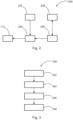
- Fig. 2 shows a block diagram of a flowcell control system 200 for a flowcell device 100 as described herein.
- the flowcell control system 200 comprises a flow control unit 202, a motor controller 204 and a motor 112.
- the flowcell control system 200 in Fig. 2 further comprises a sensor circuit 206 that sends sensor data captured by the sensor 208 corresponding to sensor 150s in Fig. 1 to the motor controller 204.
- the motor controller 204 receives flow rate values from the flow control unit 202 and controls the motor 112 for stirring the liquid inside the cell housing 102.
- the motor controller 204 may switch on and switch off the motor 112 according to the received flow rate value.
- the motor controller 204 compares the flow rate value with threshold and switches on the motor 112 when a threshold is exceeded, and switches off the motor 112 when the flow rate value is below the threshold.
- the controlling may include controlling the speed of rotation of the shaft 114 of the motor 112.
- Fig. 3 shows a flow diagram of a method 300 for sensing electrochemical process parameters in a flowcell device 100 as described herein, comprising the following steps.
- a first step 302 the flow rate of a liquid in the flowcell device 100 is controlled by a flow control unit 202, and a flow rate value of the flow rate is sent in a next step 304 to the motor controller 204.
- the flow rate value is received by the motor controller 204.
- the motor is controlled for stirring the liquid in dependence on the flow rate value.
- the step of controlling 308 the motor for stirring the liquid in dependence on the flow rate may comprise comparing the flow rate value with a pre-defined threshold and switching on the motor 112 if the threshold is exceeded, and switching off the motor 112 if the threshold falls below the threshold.
- Fig. 4a shows a graph illustrating how the reading changes without the stirrer. At low flow rates, the reading drops significantly.
- Fig. 4b shows a graph illustrating how the reading changes with the stirrer. Only a small drop can be seen, close to zero, as there is still consumption of chlorine. However, since only a small drop occurs, the sensor can operate at much lower flowrates, and also provides a more stable reading if the flowrate is fluctuating.
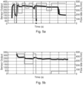
- Fig. 5a depicts a graph showing example flow rates and the respective sensor output without stirrer.
- Fig. 5b depicts a graph with example flow rates and the respective sensor output with stirrer.
- the responses in the case without stirrer are very sensitive to the flow rate. At a flow rate of 0 mL/min, the reading drops immediately and rapidly. Drops can be recognized at flow rates less than 200 mL/min. In the case with stirrer, in contrast, there are only slight differences in the readings between 0 mL/min and 400 mL/min. In the range between 0 mL/min and 50 mL/min, the sensor output is stable.
- the results can even be improved by using a greater stirrer bar size or by the speed of rotation of the stirrer.
Landscapes
- Chemical & Material Sciences (AREA)
- Life Sciences & Earth Sciences (AREA)
- Health & Medical Sciences (AREA)
- Pathology (AREA)
- General Physics & Mathematics (AREA)
- Immunology (AREA)
- Physics & Mathematics (AREA)
- Analytical Chemistry (AREA)
- Biochemistry (AREA)
- General Health & Medical Sciences (AREA)
- Chemical Kinetics & Catalysis (AREA)
- Electrochemistry (AREA)
- Molecular Biology (AREA)
- Dispersion Chemistry (AREA)
- Engineering & Computer Science (AREA)
- Food Science & Technology (AREA)
- Medicinal Chemistry (AREA)
- Flow Control (AREA)
- Mixers Of The Rotary Stirring Type (AREA)
Abstract
Description
- The invention relates to a flowcell device for sensing electrochemical process parameters, a flowcell control system, a method for sensing electrochemical process parameters in a flowcell device, and a usage of a motor in a flowcell device.
- In flowcells with, for example, a sensor for measuring chlorine ion concentrations, the sensor consumes chlorine ions. In normal operations with a sufficient high flow rate, the consumption of chlorine ions is offset by the constant replacement of ions due to the flowrate. However, if the flow drops too low, then the ions will not get replaced quickly enough. This will form a layer near the membrane surface with a lower concentration of chlorine, and the reading will drop towards zero.
- There may be a desire to provide an improved flowcell.
- The problem is solved by the subject-matter of the independent claims. Embodiments are provided by the dependent claims, the following description and the accompanying figures.
- The described embodiments similarly pertain to the flowcell device, the flowcell control system, the method for sensing electrochemical process parameters in a flowcell device, and the usage of a stirrer in a flowcell device. Synergetic effects may arise from different combinations of the embodiments although they might not be described in detail.
- Further on, it shall be noted that all embodiments of the present invention concerning a method, might be carried out with the order of the steps as described, nevertheless this has not to be the only and essential order of the steps of the method. The herein presented methods can be carried out with another order of the disclosed steps without departing from the respective method embodiment, unless explicitly mentioned to the contrary hereinafter.
- Technical terms are used by their common sense. If a specific meaning is conveyed to certain terms, definitions of terms will be given in the following in the context of which the terms are used.
- According to a first aspect, a flowcell device for sensing electrochemical process parameters is provided. The flowcell comprises a cell housing, a sensor housing for receiving a sensor, arranged at a side, e.g. an end side, of the cell housing and protruding into the cell housing; and a motor arrangement arranged at the cell housing for stirring the liquid when the flowcell is in operation.
- The electrochemical process parameters can include, for example, a concentration of molecules or ions such as chlorine ions. The sensor housing may be a housing integrated into the flowcell device where the sensor may be inserted later. Alternatively, the housing contains the sensor already when assembling the flowcell device. The sensor may comprise a sensor circuit that may receive sensed sensor signals and convert them into an analog signal or digital data to be communicated to, for example, a server or generally into a network, or which may be communicated to a motor controller that controls the motor, as described in embodiments below.
- Since the liquid is stirred by the motor arrangement, a layer with ions consumed by the sensor is disrupted, preventing the formation of a lower concentration of ions, which keeps the measurement correct.
- According to an embodiment, the motor arrangement comprises a first portion inside a motor housing such that the first portion does not contact a liquid, a second portion outside the motor housing, and a motor. The motor is configured to drive the first portion of the motor arrangement, the first portion is configured to drive the second portion of the motor arrangement, and the second portion is configured to stir the liquid when the flowcell device is in operation.
- In other words, the motor arrangement comprises a motor for driving a first portion of the motor arrangement, the first portion being not in contact with the liquid for driving a second portion of the motor arrangement, and the second portion being in contact with the liquid for stirring the liquid when the flowcell is in operation.
- The motor arrangement is also referred to as stirrer in this disclosure. The two portions of the motor arrangement effect that the stirring takes place such that the motor does not get in contact with the liquid. The first and the second portions are in physical interaction with each other, such that the second portion, which is responsible for stirring the liquid, rotates with the first portion, which is driven directly by the motor.
- According to an embodiment, the first portion of the motor arrangement comprises magnets, and the second portion of the motor arrangement comprises a magnetically effective stirrer bar, wherein the motor is configured to rotate the magnets and the magnets are configured to rotate the magnetic stirrer bar.
- The motor is for example a brushless DC motor in order to ensure a required lifetime. "Magnetically effective" means that the stirrer bar is made of magnetic material experiencing magnetic forces or being itself a permanent magnet. In embodiments, the second portion consists only of the stirrer bar. Alternatively, the second portion consists additionally of a fixing mechanism such as a pin around which the stirrer bar rotates or a rotatable disk on which the stirrer bar is mounted.
- The geometrical shape of the stirrer bar may be cuboid, but may in principal have any shape that is suitable to stir the liquid and being rotated in the magnetic field of the magnets. For example, instead of a bar-shape, the shape may be rotor-wing-like.
- According to an embodiment, the first and the second portions of the motor arrangement are water-tightly separated from each other.
- The first and the second portions are water-tightly separated from each other, so that there is no leak path into the motor. The first portion is enclosed in a housing that protrudes at the bottom of the flowcell housing into the flowcell and which is coupled in a water-tight way to the housing of the second portion. The housing of the first portion may be made of one integral piece at least in the area, where it protrudes into the flowcell. Alternatively, it may comprise a lid or a cover, which can be fastened at the top of the housing in a water-tight way. For example, the cover may comprise a thread and/or a seal.
- According to an embodiment, the flowcell device further comprises the sensor, and the sensor again comprises a membrane. The sensor is configured to sense a chemical substance inside the cell housing, more exactly inside a pipe within the cell housing, at the membrane thereby consuming a part of the chemical substance, and the second portion of the motor arrangement is configured to stir a solution comprising the chemical substance.
- The membrane is, for example, a diffusion membrane based on electrochemical measurements, which is designed to be conductive as a measuring electrode. The functionality of the sensor thus may comprise consuming the chemical substance, for example molecules or ions such as chlorine ions, at the membrane as the reaction takes place. Conventionally, if the flow drops too low, then the ions will not get replaced quickly enough. This will form a layer near the membrane surface of the sensor with a lower concentration of chlorine, and the reading will drop towards zero. If the stirrer is turned on, then this will agitate the sample, i.e., the liquid, around the membrane surface, and stop this layer of lower concentration from forming. This means that the sensor can operate at a significantly lower flowrate.
- The device therefore ensures a significantly improved measurement quality or prevents incorrect measurements at changing or low flow rates. In these cases a concentration gradient near the membrane is avoided and the concentration is detected correctly.
- According to an embodiment, the flowcell device further comprises a pipe configured to receive a fluid from an inlet of the flowcell device and to direct the liquid to an outlet of the flowcell device. The membrane is disposed on a side of the sensor facing the motor arrangement. The sensor protrudes sufficiently from the sensor housing into the pipe toward the motor arrangement to leave only a gap between the stirrer bar and the membrane.
- A "gap" means that the distance and hence the space or volume between the stirrer bar and the membrane is small. For example, the distance is in the same order of size as the diameter of the inlet. By minimizing this volume, the speed of response of the sensor is increased significantly. The gap may be realized for example by dimensioning the size, i.e., length of the sensor, or the size or length of the sensor housing, by the location of the motor arrangement, in particular the stirrer bar, which may be for example near the inlet, or by dimensioning the size of the flowcell device itself.
- According to an embodiment, the flowcell device further comprises a transmitter, and the sensor and the motor are powered from the transmitter.
- In other words, a signal from a transmitter switches on the sensor and the motor at the same time. The motor may then remain in a switched-on state until a signal from a transmitter indicates switching off the sensor and the motor.
- In some of the following measures are presented to improve efficiency and to extend the motor lifetime.
- According to an embodiment, the flowcell device further comprises a flow control unit configured to determine a flow rate of the liquid running through the housing of the flowcell device, and the flowcell device further comprises a motor controller configured to control the motor according to the determined flow rate of the liquid.
- In other words, the flow rate is controlled by the flow control unit. That is, the flow control unit having information about the flow rate of the liquid, communicates the flow rate to the controller that controls the motor, which is also referred to as motor controller in the following. The motor controller then switches the motor on and off in dependence on the flow rate. As an example, the controller switches on the motor if the flow rate falls below a pre-determined threshold. The same threshold or a different threshold may be used for switching off the motor if the flow rate exceeds this threshold. In alternative embodiments, the motor controller may control the motor in dependence on the rate of change of the concentration. For example, the control unit is configured to provide a control signal for controlling the motor in dependence on the determined flow rate of the liquid.
- For example, the motor may be switched on as soon as the concentration drops. In this case, pre-determined thresholds and observation time intervals in which the drop of concentration is to be detected may be applied.
- In contrast to switching the motor on or off, in this embodiment, the rotation speed may be adapted to the flow rate of the liquid through the flowcell. The described options may be mixed. For example, conditions may be determined and different thresholds may be applied at which the motor is stopped or switched on and at which the rotation speed is adapted. Conditions may, for example be a concentration or the rate of change of the concentration as described above.
- According to an embodiment, the motor controller activates the motor in time intervals.
- The time intervals may be regular, pre-determined time intervals or may be dependent on the flow rate or change rate of the concentration or other criteria.
- According to an embodiment, the motor and the first portion are a modular unit attachable to the housing of the flowcell device.
- Due to the separation of the first portion and the second portion, the first portion and the second portion may be designed in a modular way, such that, for example, the motor can be easily exchanged, upgraded, etc. For example, the motor controller can be exchanged to have a microprocessor, the software may be updated, or there may be modules with different types of motors, etc.
- According to an aspect, a usage of a stirrer in a flowcell device for stirring a liquid inside the housing of the flowcell device is provided.
- The stirrer consists of a motor arrangement as described herein. The motor drives a stirrer bar and is arranged at the housing of the flowcell. The transmission of the rotation of the motor and the stirrer bar is realized using magnetic forces.
- According to an aspect, a flowcell control system for a flowcell device is provided. The flowcell control system comprises a motor, a motor controller and a flow control unit. The flow control unit is configured to control a flow rate of a liquid in the flowcell and to send a flow rate value of the flow rate to a motor controller. The motor controller is configured to receive the flow rate value and to control a motor for stirring the liquid, and the motor configured to be controlled by the motor controller.
- The flowcell control system comprises the electrical components of the flowcell device, especially control means with respect to the stirring such as the flow control unit and the motor controller, and the motor to be controlled. The flowcell control system may further comprise communication means, for example, for communicating the flow rate and control signals.
- According to an embodiment, the flowcell control system further comprises a sensor circuit configured to detect an electrochemical process parameter sensed by a sensor of the flowcell device, wherein the sensor circuit is configured to send an electrochemical process parameter value to the motor controller, and wherein the motor controller is configured to control the motor using the electrochemical process parameter value.
- The sensor circuit may be part of the sensor or a separate processing unit. The sensor circuit is the electronic part of that converts the sensing into analog signals and/or digital output signals and which represents the interface to further data or signal processing devices, such as network devices, clients or servers, or it may be itself a human machine interface.
- According to an aspect, a method for sensing electrochemical process parameters in a flowcell device is provided, comprising the following steps. In a first step, a flow rate of a liquid in the flowcell device is controlled by a flow control unit. In a second step a flow rate value of the flow rate is sent to a motor controller by the flow control unit. In a third step, the flow rate value is received by a motor controller and in a fourth step, the motor is controlled for stirring the liquid in dependence on the flow rate value by the motor controller.
- According to an embodiment, the step controlling the motor for stirring the liquid in dependence on the flow rate comprises comparing the flow rate value with a pre-defined threshold and switching on the motor if the threshold is exceeded, and switching off the motor if the threshold falls below the threshold.
- There may be two different thresholds for switching off such that a hysteresis is obtained. Further, instead of switching, the rotation speed may be controlled.
- The communication between the control unit and the motor controller for providing the flow rate may be realized by a wired connection, over which an analog or digital signal is transmitted to the motor controller. Alternatively, the communication takes place over a wireless connection to any known communication standard, especially a short range communication standard. The control of the motor is realized in any suitable way known to a skilled person. E.g. the control is performed using analog and/or digital circuits and by providing a control current or control voltage to the motor. The digital circuits may include logic elements or logic devices, programmable devices such as a CPLD, an FPGA, a microprocessor, etc. Further the motor controller may include memory devices to accommodate software or data, and/or to log the control actions.
-
- Fig. 1
- shows a sketch of a flowcell device,
- Fig. 2
- shows a block diagram of a flowcell control system,
- Fig. 3
- shows a flow diagram of a method for sensing electrochemical process parameters in a flowcell device,
- Fig. 4a
- shows a graph illustrating how the reading changes without the stirrer,
- Fig. 4b
- shows a graph illustrating how the reading changes with the stirrer,
- Fig. 5a
- depicts a graph showing example flow rates and the respective sensor output without stirrer,
- Fig. 5b
- depicts a graph with example flow rates and the respective sensor output with stirrer.
- Corresponding parts are provided with the same reference symbols in all figures.
-
Fig. 1 shows a sketch of aflowcell device 100 for sensing electrochemical process parameters. Theflowcell device 100 comprises acell housing 102, asensor housing 104 for receiving asensor 150, arranged at a top side of thecell housing 102 and protruding into thecell housing 102. The liquid flow enters theflowcell device 100 on the bottom left through the inlet orspigot 142. It then passes across themembrane 154 of thesensor 150, and flows through the gap between thesensor 150 and the wall of thepipe 156 to theoutlet 144 of theflowcell device 100, where the liquid or "sample" flows out of theflowcell device 100. - The
flowcell device 100 comprises further amotor arrangement 110 located at a bottom side of thecell housing 102 with amotor 112, afirst portion 120 and asecond portion 130. Themotor 112 drives ashaft 114 of themotor 112 at its center that is fixed to thefirst portion 120, such that thefirst portion 120 rotates whenshaft 114 rotates. That is, themotor 112 is configured to drive theshaft 114, and hence thefirst portion 120.Magnets 122 are fixed decentral at the top of thefirst portion 120 such that they can rotate together with thefirst portion 120. Thefirst portion 120 may consist of a housing which encloses a free space and themagnets 122. Alternatively, it may be filled with a light-weight rigid material such as plastic or a porous material supporting the adhesion of themagnets 122 on the top side of the first portion's housing. Thefirst portion 120 is therefore inside the housing of themotor arrangement 110 and has no contact with the liquid of theflowcell device 100. - Outside this motor housing, at its top surface, the
second portion 130 is arranged. Thesecond portion 130 comprises astirrer bar 132 that is arranged centrally at the top surface of the motor housing. Thestirrer bar 132 consists at least partly of magnetic material or is itself a magnet such that it interacts with themagnets 122. That is, when themagnets 122 rotate, thestirrer bar 132 rotates, too. Thestirrer bar 132 may be fixed to the housing of themotor 112 using a pin at its rotation axis or may be fixed solely by the magnetic forces if themagnets 122 are permanent magnets. - The volume of
liquid 152 in the flowcell may be minimized in order to make the speed of response of the sensor as fast as possible. This is achieved by minimizing thefree volume 152, i.e., the volume where the fluid can flow, between themembrane 154 and bottom of thepipe 156, and hence the distance between themembrane 154 and second portion of the motor arrangement, where the stirrer bar is located. "Minimizing" means as small as possible but large enough space for ensuring a free flow without flow resistance. For example, the free space orvolume 152 is in the order of size of theinlet 142 oroutlet 144. For example, the distance between the membrane and the stirrer bar is in the same order of size as the diameter of the inlet. In this way, a movement of thestirrer bar 132 has nearly an immediate impact on the concentration of ions or molecules at themembrane 154. As shown in the example ofFig. 1 , the minimization of thefree volume 152 is realized by having thesensor 150 protrude far enough into thepipe 156 to leave only a gap between themembrane 154 and the bottom of the pipe, which abuts the housing of the motor arrangement and on which thestirrer bar 132 is located. As can be seen fromFig. 1 , also the diameter of thepipe 156 is small such that there is only a small gap between thesensor 150 and the wall of thepipe 156. As a result, the fluid moved by the stirrer bar toward the wall of thepipe 156 is reflected by the wall and in this way assists in providing ions at the depleted fluid layer near themembrane 154. - The
flowcell device 100 comprises further afastening arrangement 140, which provides for modular assembling a device with further modules such as the shownflowcell device 100. The modules can be attached to each other, for example, with a bracket that is slid over twofastening arrangements 140 of two modules. - The terms "top" and "bottom" relate to an orientation as shown in
Fig. 1 . The shown orientation of the flowcell device and its components is only an example and does not necessarily correspond to the orientation of gravity. Further, the locations of the components may be exchanged in terms of top/bottom. Similarly, the flow may be in the reverse direction. -
Fig. 2 shows a block diagram of aflowcell control system 200 for aflowcell device 100 as described herein. Theflowcell control system 200 comprises aflow control unit 202, amotor controller 204 and amotor 112. Theflowcell control system 200 inFig. 2 further comprises asensor circuit 206 that sends sensor data captured by thesensor 208 corresponding to sensor 150s inFig. 1 to themotor controller 204. Themotor controller 204 receives flow rate values from theflow control unit 202 and controls themotor 112 for stirring the liquid inside thecell housing 102. Themotor controller 204 may switch on and switch off themotor 112 according to the received flow rate value. For example, themotor controller 204 compares the flow rate value with threshold and switches on themotor 112 when a threshold is exceeded, and switches off themotor 112 when the flow rate value is below the threshold. Alternatively, or in combination, the controlling may include controlling the speed of rotation of theshaft 114 of themotor 112. -
Fig. 3 shows a flow diagram of amethod 300 for sensing electrochemical process parameters in aflowcell device 100 as described herein, comprising the following steps. In afirst step 302, the flow rate of a liquid in theflowcell device 100 is controlled by aflow control unit 202, and a flow rate value of the flow rate is sent in anext step 304 to themotor controller 204. Instep 306 the flow rate value is received by themotor controller 204. Instep 308, the motor is controlled for stirring the liquid in dependence on the flow rate value. The step of controlling 308 the motor for stirring the liquid in dependence on the flow rate may comprise comparing the flow rate value with a pre-defined threshold and switching on themotor 112 if the threshold is exceeded, and switching off themotor 112 if the threshold falls below the threshold. -
Fig. 4a shows a graph illustrating how the reading changes without the stirrer. At low flow rates, the reading drops significantly.Fig. 4b shows a graph illustrating how the reading changes with the stirrer. Only a small drop can be seen, close to zero, as there is still consumption of chlorine. However, since only a small drop occurs, the sensor can operate at much lower flowrates, and also provides a more stable reading if the flowrate is fluctuating. -
Fig. 5a depicts a graph showing example flow rates and the respective sensor output without stirrer.Fig. 5b depicts a graph with example flow rates and the respective sensor output with stirrer. The responses in the case without stirrer are very sensitive to the flow rate. At a flow rate of 0 mL/min, the reading drops immediately and rapidly. Drops can be recognized at flow rates less than 200 mL/min. In the case with stirrer, in contrast, there are only slight differences in the readings between 0 mL/min and 400 mL/min. In the range between 0 mL/min and 50 mL/min, the sensor output is stable. - The results can even be improved by using a greater stirrer bar size or by the speed of rotation of the stirrer.
- Other variations to the disclosed embodiments can be understood and effected by those skilled in the art in practicing the claimed invention, from the study of the drawings, the disclosure, and the appended claims. In the claims, the word "comprising" does not exclude other elements or steps and the indefinite article "a" or "an" does not exclude a plurality. A single processor or other unit may fulfill the functions of several items or steps recited in the claims. The mere fact that certain measures are recited in mutually different dependent claims does not indicate that a combination of these measures cannot be used to advantage. Any reference signs in the claims should not be construed as limiting the scope of the claims.
-
- 100
- Flowcell device
- 102
- Cell housing
- 104
- Sensor housing
- 110
- Motor arrangement
- 112
- Motor
- 114
- Shaft
- 120
- First portion of motor arrangement
- 122
- Magnets
- 130
- Second portion of motor arrangement
- 132
- Stirrer bar
- 140
- Fastening arrangement
- 142
- Spigot / Inlet
- 144
- Outlet
- 150
- Sensor
- 152
- Free volume/space between membrane and bottom of pipe
- 154
- Membrane of sensor
- 156
- Pipe
- 200
- Flowcell control system
- 202
- Flow control unit
- 204
- Motor Controller
- 206
- Sensor circuit
- 208
- Sensor
- 300
- Method
- 302
- First method step
- 304
- Second method step
- 306
- Third method step
- 308
- Fourth method step
Claims (15)
- Flowcell device (100) for sensing electrochemical process parameters; wherein the flowcell comprisesa cell housing (102);a sensor housing (104) for receiving a sensor (150, 208), arranged at a side of the cell housing (102) and protruding into the cell housing (102); anda motor arrangement (110) arranged at the cell housing (102) for stirring the liquid when the flowcell device (100) is in operation.
- Flowcell device (100) according to claim 1, wherein the motor arrangement (110) comprisesa first portion (120) inside a motor housing such that the first portion does not contact a liquid,a second portion (130) outside the motor housing, anda motor (112);wherein the motor (112) is configured to drive the first portion (120) of the motor arrangement (110),wherein the first portion (120) is configured to drive the second portion (130) of the motor arrangement (110),and wherein the second portion (130) is configured to stir the liquid when the flowcell device (100) is in operation.
- Flowcell device (100) according to claim 1 or 2, wherein the first portion (120) of the motor arrangement (110) comprises magnets (122), and the second portion (130) of the motor arrangement (110) comprises a magnetically effective stirrer bar (132), wherein the motor (112) is configured to rotate the magnets (122), and the magnets (122) are configured to rotate the magnetic stirrer bar (132).
- Flowcell device (100) according to any of the previous claims, wherein the first (120) and the second (130) portions of the motor arrangement (110) are water-tightly separated from each other.
- Flowcell device (100) according to any one of the previous claims, wherein the flowcell device (100) further comprises the sensor (150) with a membrane (154), and wherein the sensor (150) is configured to sense a chemical substance inside the cell housing (102) at the membrane (154), thereby consuming a part of the chemical substance, and the second portion (130) of the motor arrangement (110) is configured to stir a solution comprising the chemical substance.
- Flowcell device (100) according to claim 5,wherein the flowcell device (100) further comprises a pipe (156) configured to receive a fluid from an inlet (142) of the flowcell device (100) and to direct the liquid to an outlet (144) of the flowcell device (100);wherein the membrane (154) is disposed on a side of the sensor (150) facing the motor arrangement (110); andwherein the sensor (150) protrudes sufficiently from the sensor housing (104) into the pipe (156) toward the motor arrangement (110) to leave only a gap between the stirrer bar (132) and the membrane (154).
- Flowcell device (100) according to any one of the previous claims, wherein the flowcell device (100) further comprises a transmitter, and the sensor (150, 208) and the motor (112) are powered from the transmitter.
- Flowcell device (100) according to any one of the previous claims,wherein the flowcell device (100) further comprises a flow control unit (202) configured to determine a flow rate of the liquid running through the cell housing (102) of the flowcell device (100), andwherein the flowcell device (100) further comprises a motor controller (204) configured to control the motor (112) according to the determined flow rate of the liquid.
- Flowcell device (100) according to claim 8, wherein the motor controller (204) activates the motor (112) in time intervals.
- Flowcell device (100) according to any one of the previous claims, wherein the motor (112) and the first portion (120) are a modular unit attachable to the cell housing (102) of the flowcell device (100).
- Flowcell control system (200) for a flowcell device (100) according to any of claims 1 to 10 comprisinga flow control unit (202) configured to control a flow rate of a liquid in the flowcell device (100) and to send a flow rate value of the flow rate to a motor controller (204);the motor controller (204) configured to receive the flow rate value and to control a motor (112) for stirring the liquid;a motor (112) configured to be controlled by the motor controller (204).
- Flowcell control system (200) according to claim 11, further comprising a sensor circuit (206) configured to detect an electrochemical process parameter sensed by a sensor (208) of the flowcell device (100); wherein the sensor circuit (206) is configured to send an electrochemical process parameter value to the motor controller (204); and wherein the motor controller (204) is configured to control the motor (112) using the electrochemical process parameter value.
- Method (300) for sensing electrochemical process parameters in a flowcell device (100) according to claim 1, comprising the steps:Controlling (302), by a flow control unit (202), a flow rate of a liquid in the flowcell device (100) andSending (304) a flow rate value of the flow rate to a motor controller (204);Receiving (306), by the motor controller (204), the flow rate value andControlling (308) the motor (112) for stirring the liquid in dependence on the flow rate value.
- Method (300) according to claim 13, wherein the step controlling (308) the motor for stirring the liquid in dependence on the flow rate comprises comparing the flow rate value with a pre-defined threshold and switching on the motor (112) if the threshold is exceeded; and switching off the motor (112) if the threshold falls below the threshold.
- Usage of a stirrer (110) in a flowcell device (100) according to any one of claims 1 - 10 for stirring a liquid inside the cell housing (102) of the flowcell device (100).
Priority Applications (3)
| Application Number | Priority Date | Filing Date | Title |
|---|---|---|---|
| EP23151826.7A EP4400838A1 (en) | 2023-01-16 | 2023-01-16 | Flowcell device, flowcell control system and method |
| CN202410048932.7A CN118348095A (en) | 2023-01-16 | 2024-01-12 | Flow cell apparatus, flow cell control system and method |
| US18/413,420 US20240241033A1 (en) | 2023-01-16 | 2024-01-16 | Flowcell Device, Flowcell Control System and Method |
Applications Claiming Priority (1)
| Application Number | Priority Date | Filing Date | Title |
|---|---|---|---|
| EP23151826.7A EP4400838A1 (en) | 2023-01-16 | 2023-01-16 | Flowcell device, flowcell control system and method |
Publications (1)
| Publication Number | Publication Date |
|---|---|
| EP4400838A1 true EP4400838A1 (en) | 2024-07-17 |
Family
ID=84981265
Family Applications (1)
| Application Number | Title | Priority Date | Filing Date |
|---|---|---|---|
| EP23151826.7A Pending EP4400838A1 (en) | 2023-01-16 | 2023-01-16 | Flowcell device, flowcell control system and method |
Country Status (3)
| Country | Link |
|---|---|
| US (1) | US20240241033A1 (en) |
| EP (1) | EP4400838A1 (en) |
| CN (1) | CN118348095A (en) |
Citations (6)
| Publication number | Priority date | Publication date | Assignee | Title |
|---|---|---|---|---|
| GB1531000A (en) * | 1975-12-09 | 1978-11-01 | Technicon Instr | Method and apparatus for proportioning liquids |
| US5235526A (en) * | 1990-11-27 | 1993-08-10 | Solomat Limited | Multi-probed sonde including microprocessor |
| US20030177851A1 (en) * | 2002-02-06 | 2003-09-25 | Henry Kent D. | Sensor head apparatus |
| US20090301175A1 (en) * | 2006-02-06 | 2009-12-10 | Hach Lange Gmbh | Waste water immersion probe |
| US8479598B2 (en) * | 2005-10-28 | 2013-07-09 | Intellitect Water Limited | Probe or sonde for investigating fluids |
| CN213780065U (en) * | 2020-10-28 | 2021-07-23 | 北京欧仕科技有限公司 | Automatic water quality monitor |
-
2023
- 2023-01-16 EP EP23151826.7A patent/EP4400838A1/en active Pending
-
2024
- 2024-01-12 CN CN202410048932.7A patent/CN118348095A/en active Pending
- 2024-01-16 US US18/413,420 patent/US20240241033A1/en active Pending
Patent Citations (6)
| Publication number | Priority date | Publication date | Assignee | Title |
|---|---|---|---|---|
| GB1531000A (en) * | 1975-12-09 | 1978-11-01 | Technicon Instr | Method and apparatus for proportioning liquids |
| US5235526A (en) * | 1990-11-27 | 1993-08-10 | Solomat Limited | Multi-probed sonde including microprocessor |
| US20030177851A1 (en) * | 2002-02-06 | 2003-09-25 | Henry Kent D. | Sensor head apparatus |
| US8479598B2 (en) * | 2005-10-28 | 2013-07-09 | Intellitect Water Limited | Probe or sonde for investigating fluids |
| US20090301175A1 (en) * | 2006-02-06 | 2009-12-10 | Hach Lange Gmbh | Waste water immersion probe |
| CN213780065U (en) * | 2020-10-28 | 2021-07-23 | 北京欧仕科技有限公司 | Automatic water quality monitor |
Also Published As
| Publication number | Publication date |
|---|---|
| CN118348095A (en) | 2024-07-16 |
| US20240241033A1 (en) | 2024-07-18 |
Similar Documents
| Publication | Publication Date | Title |
|---|---|---|
| US11214502B2 (en) | Hub and removable cartridge for producing and delivering ozonated water | |
| CN103348233B (en) | Amperometric sensor system | |
| US9671254B2 (en) | Magnetic sensing to detect tampering with a utility meter | |
| EP2647968A2 (en) | Apparatus and method of measuring a flow within a meter | |
| US20120324995A1 (en) | System and Method For Product Level Monitoring in A Chemical Dispensing System | |
| EP4400838A1 (en) | Flowcell device, flowcell control system and method | |
| KR0121130B1 (en) | Weighing method and apparatus for water in a refrigerator | |
| JP2007316770A (en) | Sensor device, sensor system, and sensor device connection method capable of detecting different physical quantities | |
| JP2019128311A (en) | Sensor | |
| US20230296678A1 (en) | Wireless process variable transmitter with removable power module | |
| JP5755883B2 (en) | Liquid property analyzer | |
| JP6372302B2 (en) | Free residual chlorine measuring device | |
| US5614067A (en) | Leaching device for electrolyzed silver | |
| JP3390154B2 (en) | Residual chlorine meter and water purification device using it | |
| KR20080014446A (en) | Electronic water meter and its control method | |
| JP2013242170A (en) | Residual chlorine measuring apparatus | |
| WO2002044657A2 (en) | Method for detecting faulty liquid level sensors | |
| KR102259929B1 (en) | Hybrid Electric Water meter | |
| US12270775B2 (en) | Sensor | |
| CN220257890U (en) | Stirring shaft rotation detection alarm system for stirring device | |
| CN1443299A (en) | Device for measuring/determining physical quantity of medium | |
| CN114137054A (en) | Measuring device | |
| EP4500165A1 (en) | Ph sensor with secondary reference electrode | |
| US20230219828A1 (en) | Autonomous water analysis device and swimming pool equipped with such a device | |
| CN111156710A (en) | Combination switch and plumbing blanket host including the combination switch |
Legal Events
| Date | Code | Title | Description |
|---|---|---|---|
| PUAI | Public reference made under article 153(3) epc to a published international application that has entered the european phase |
Free format text: ORIGINAL CODE: 0009012 |
|
| STAA | Information on the status of an ep patent application or granted ep patent |
Free format text: STATUS: THE APPLICATION HAS BEEN PUBLISHED |
|
| AK | Designated contracting states |
Kind code of ref document: A1 Designated state(s): AL AT BE BG CH CY CZ DE DK EE ES FI FR GB GR HR HU IE IS IT LI LT LU LV MC ME MK MT NL NO PL PT RO RS SE SI SK SM TR |
|
| STAA | Information on the status of an ep patent application or granted ep patent |
Free format text: STATUS: REQUEST FOR EXAMINATION WAS MADE |
|
| 17P | Request for examination filed |
Effective date: 20241204 |
|
| RBV | Designated contracting states (corrected) |
Designated state(s): AL AT BE BG CH CY CZ DE DK EE ES FI FR GB GR HR HU IE IS IT LI LT LU LV MC ME MK MT NL NO PL PT RO RS SE SI SK SM TR |
|
| STAA | Information on the status of an ep patent application or granted ep patent |
Free format text: STATUS: EXAMINATION IS IN PROGRESS |
|
| 17Q | First examination report despatched |
Effective date: 20250828 |