EP4400815A1 - Modular flowcell unit and flowcell assembly - Google Patents
Modular flowcell unit and flowcell assembly Download PDFInfo
- Publication number
- EP4400815A1 EP4400815A1 EP23151833.3A EP23151833A EP4400815A1 EP 4400815 A1 EP4400815 A1 EP 4400815A1 EP 23151833 A EP23151833 A EP 23151833A EP 4400815 A1 EP4400815 A1 EP 4400815A1
- Authority
- EP
- European Patent Office
- Prior art keywords
- flowcell
- unit
- modular
- sensor
- sample
- Prior art date
- Legal status (The legal status is an assumption and is not a legal conclusion. Google has not performed a legal analysis and makes no representation as to the accuracy of the status listed.)
- Pending
Links
- 239000012530 fluid Substances 0.000 claims abstract description 35
- ZAMOUSCENKQFHK-UHFFFAOYSA-N Chlorine atom Chemical compound [Cl] ZAMOUSCENKQFHK-UHFFFAOYSA-N 0.000 claims description 15
- 239000000460 chlorine Substances 0.000 claims description 13
- 229910052801 chlorine Inorganic materials 0.000 claims description 13
- 239000000126 substance Substances 0.000 claims description 11
- 230000003287 optical effect Effects 0.000 claims description 6
- 238000001914 filtration Methods 0.000 claims description 5
- 238000012795 verification Methods 0.000 claims description 5
- 238000003306 harvesting Methods 0.000 claims description 4
- QVGXLLKOCUKJST-UHFFFAOYSA-N atomic oxygen Chemical compound [O] QVGXLLKOCUKJST-UHFFFAOYSA-N 0.000 claims description 3
- 230000005611 electricity Effects 0.000 claims description 3
- 239000000706 filtrate Substances 0.000 claims description 2
- 230000033116 oxidation-reduction process Effects 0.000 claims description 2
- 229910052760 oxygen Inorganic materials 0.000 claims description 2
- 239000001301 oxygen Substances 0.000 claims description 2
- 238000010586 diagram Methods 0.000 description 14
- 238000000034 method Methods 0.000 description 6
- 238000013461 design Methods 0.000 description 4
- 230000014759 maintenance of location Effects 0.000 description 4
- 238000004140 cleaning Methods 0.000 description 3
- 230000007246 mechanism Effects 0.000 description 3
- 238000004891 communication Methods 0.000 description 2
- 230000001419 dependent effect Effects 0.000 description 2
- 238000012544 monitoring process Methods 0.000 description 2
- 230000008569 process Effects 0.000 description 2
- 239000007787 solid Substances 0.000 description 2
- OKTJSMMVPCPJKN-UHFFFAOYSA-N Carbon Chemical compound [C] OKTJSMMVPCPJKN-UHFFFAOYSA-N 0.000 description 1
- 230000008901 benefit Effects 0.000 description 1
- 229910052799 carbon Inorganic materials 0.000 description 1
- 230000000295 complement effect Effects 0.000 description 1
- 230000006835 compression Effects 0.000 description 1
- 238000007906 compression Methods 0.000 description 1
- 239000000356 contaminant Substances 0.000 description 1
- 230000029087 digestion Effects 0.000 description 1
- 230000005662 electromechanics Effects 0.000 description 1
- 238000002955 isolation Methods 0.000 description 1
- 239000007788 liquid Substances 0.000 description 1
- 238000004519 manufacturing process Methods 0.000 description 1
- 230000036316 preload Effects 0.000 description 1
- 238000005086 pumping Methods 0.000 description 1
- 230000009467 reduction Effects 0.000 description 1
- 230000002195 synergetic effect Effects 0.000 description 1
Images




Classifications
-
- G—PHYSICS
- G01—MEASURING; TESTING
- G01F—MEASURING VOLUME, VOLUME FLOW, MASS FLOW OR LIQUID LEVEL; METERING BY VOLUME
- G01F15/00—Details of, or accessories for, apparatus of groups G01F1/00 - G01F13/00 insofar as such details or appliances are not adapted to particular types of such apparatus
- G01F15/18—Supports or connecting means for meters
- G01F15/185—Connecting means, e.g. bypass conduits
-
- G—PHYSICS
- G01—MEASURING; TESTING
- G01N—INVESTIGATING OR ANALYSING MATERIALS BY DETERMINING THEIR CHEMICAL OR PHYSICAL PROPERTIES
- G01N15/00—Investigating characteristics of particles; Investigating permeability, pore-volume or surface-area of porous materials
- G01N15/10—Investigating individual particles
- G01N15/14—Optical investigation techniques, e.g. flow cytometry
- G01N15/1434—Optical arrangements
- G01N15/1436—Optical arrangements the optical arrangement forming an integrated apparatus with the sample container, e.g. a flow cell
-
- G—PHYSICS
- G01—MEASURING; TESTING
- G01N—INVESTIGATING OR ANALYSING MATERIALS BY DETERMINING THEIR CHEMICAL OR PHYSICAL PROPERTIES
- G01N33/00—Investigating or analysing materials by specific methods not covered by groups G01N1/00 - G01N31/00
-
- G—PHYSICS
- G01—MEASURING; TESTING
- G01N—INVESTIGATING OR ANALYSING MATERIALS BY DETERMINING THEIR CHEMICAL OR PHYSICAL PROPERTIES
- G01N33/00—Investigating or analysing materials by specific methods not covered by groups G01N1/00 - G01N31/00
- G01N33/18—Water
- G01N33/1893—Water using flow cells
-
- G—PHYSICS
- G01—MEASURING; TESTING
- G01N—INVESTIGATING OR ANALYSING MATERIALS BY DETERMINING THEIR CHEMICAL OR PHYSICAL PROPERTIES
- G01N35/00—Automatic analysis not limited to methods or materials provided for in any single one of groups G01N1/00 - G01N33/00; Handling materials therefor
- G01N2035/00178—Special arrangements of analysers
- G01N2035/00326—Analysers with modular structure
Definitions
- the invention relates to a modular flowcell unit, a flowcell assembly, and the use of a modular flowcell unit.
- Flowcells are used for mounting specific sensors and controlling the flowrate by a flow controller. Usually, flowcells are specialized to individual sensor parameters. It is difficult to find a flowcell that is compatible with multiple sensor types. Use of a single flowcell design for multiple sensor variants allows simplified manufacturing, fewer variants and cost reduction.
- a modular flowcell unit comprises a mechanical fixing interface configured for receiving a further modular flowcell unit, and a fluid interface configured for receiving fluid from the further modular flowcell unit or for transferring fluid to the further modular flowcell unit.
- the modular flowcell unit is a single unit intended to being connected to at least one further modular flowcell unit.
- it comprises a mechanical fixing interface, e.g. on one side or on two sides of the flowcell unit.
- the modular flowcell unit may also be used stand-alone, if the functionality of the further modules is not required.
- each modular unit can be flowed through by the fluid, herein also called “sample”. This means that the fluid can be passed from one modular unit to another modular unit, the fluid can flow through this unit and be passed to yet another modular unit, etc., so that a chain of modular units can be formed. Two connections are necessary to couple the units.
- the two connections are interrelated because the fixing must ensure the flow of the liquid, and that the whole arrangement, especially the flow connection, is mechanically stable.
- a further connection might optionally be an electric connection, where "electric” may mean power, data, control signals, etc. Some of the electric connections may be achieved by a wireless connection.
- the modular flowcell units may be used in isolation.
- the design allows individual cells to be mounted directly to fluid hoses.
- the brackets are not used to attach the modular flowcell unit to the side of other components, but only to attach the modular flowcell unit to the customer's wall, bracket, or panel, etc.
- the modular flowcell units may also be used with other modular flowcell units, end cells, that is, modular flowcell units that have a fluid interface or spigot for connecting to another modular flowcell unit only on one side, or regulators using the spigot part as an intermediary fluid connection.
- the mechanical fixing interface comprises a lateral plate enclosed with a protruding edge into which a connection element can be inserted.
- connection element may be for example a bracket.
- “Lateral” addresses those sides of the flowcell unit where the inlet and/or the outlet for the fluid is located.
- the inlet and the outlet may be located at opposite sides, although this is not a requirement.
- the outlet side may be located at the side adjacent to the inlet side, which form a 90° angle. In case of lateral inlet and outlet sides, these sides may also be denominated “left” and "right” sides from view of a front side.
- “Backside” may be defined to be the side facing to a wall to which the flowcell unit may be mounted, and the front side is then consequently the remaining side opposite to the backside.
- the plates may be located at the left and/or right sides, where the further modular flowcell units can be attached to the modular flowcell unit.
- the outer surface of a plate may be longer and/or wider than the main body of the plates such that protruding edges are formed.
- the adjacent edges of the flowcell unit and a further flowcell unit to be connected to the flowcell unit may then form a common pair of edges.
- a bracket having a longitudinal slot can be moved over this pair of edges such that the pair of edges slips into the slot. In this way, the edges are kept together and the flowcell units are fixed to each other. Other fixing arrangements may be applied.
- This bracket/plate can then be used to mount the joined units to a wall or other bracket. Other mounting arrangements and locations may be applied.
- the plates may be formed by the housing.
- the plates may be integral with the housing and a part of the housing, such that they form the wall of the modular flowcell unit.
- the plate or the wall are therefore configured for laterally abutting with a further modular flowcell unit if the further modular flowcell unit is received by the mechanical fixing interface.
- one of the narrow sides, i.e., circumferential sides, of the plate or the wall comprises a spring-loaded pin for fixing a connection element to the modular flowcell unit.
- the narrow side may have a groove or a gap, in which the spring-loaded pin is embedded.
- connection element may be a bracket as described above.
- the spring-loaded pin or spring plunger may comprise a lock element such as the pin itself, a ball-like element, a cuboid-shaped element or another suitable element, which is pressed against the force of the spring into the groove or gap at one of the narrow sides of the plate when the connection element is moved over the protruding edges.
- the lock element is pressed by the force of the spring into the groove of the connection element such that the connection element is removable locked.
- there are spring-loaded pin s on opposite sides of the narrow sides of the plate e.g. a top side and a bottom side.
- the modular flowcell unit further comprises a sample inlet configured to be connectable to a sample outlet of a further modular flowcell unit and a sample outlet configured to be connectable to a sample inlet of a further modular flowcell unit, and/or an electrical interface to a further modular flowcell unit.
- the sample inlet may receive the sample either from another modular flowcell unit or from an external source.
- receive the sample from another modular flowcell unit it has to be connectable to the outlet of another modular flowcell unit. Accordingly, the sample outlet outputs the sample either to another modular flowcell unit or to an external sink.
- the inlets and outlets may therefore be arranged at such heights or locations that a chain can be built.
- the fluid can pass from one to another flowcell unit, and also through these units to further units.
- the cells may be constructed such that an inlet may be used also as outlet and vice versa.
- two identical cells can be connected by turning one of the cells by 180° such that, from a front view, the left and backside of the second cell, turns to be the right and the front side. Then, the outlet of the first cell is on the same height as the inlet of the second cell, or vice versa.
- the cells may have a plurality of inlets/outlets on one side, which can be used as required by an application.
- a specialized flowcell unit may have inlets or outlets at individual heights.
- a flowcell unit may be designed to be a modular end cell, which is connectable only on one side to another modular flowcell unit.
- the flowcell unit may comprise an electrical interface to a further modular flowcell unit.
- the electrical interface may provide control lines for control signals, data lines and/or power lines.
- the modular flowcell unit is a sensor flowcell unit, herein also referred to as "sensor module” comprising a fitting that is configured to receive a sensor.
- the sensor flowcell unit is therefore not only modular with respect to further flowcell units but also with respect to its sensor functionality.
- the sensor flowcell unit may comprise only a fitting for a sensor not including the sensor.
- the sensor can be installed later.
- the fitting is independent on the type of sensor to be fitted so that different types of sensors may be received by such a universal fitting.
- the sensor may be already integrated into the fitting when assembling the flowcell module and therefore be part of the sensor flowcell unit.
- sensor flowcell units for different sensor body size categories or shape categories.
- the sensor flowcell unit comprises a sensor for sensing one of: a pH concentration, an oxidation-reduction potential (ORP), a chlorine concentration, or a dissolved oxygen concentration.
- ORP oxidation-reduction potential
- the fitting allows, for example, receiving any sensor that is contained within a %"-sized fitting or "sensor body".
- any sensor that is contained within a %"-sized fitting or "sensor body".
- sensor body For example, pH-, ORP-, chlorine-, and dissolved oxygen-sensors as well as other sensors are suitable for such a fitting.
- the modular flowcell unit is a flow control module comprising a flow control arrangement or a sensor module.
- the modular design makes it possible to separate the flow control from the sensor system and thus integrate a number of functions into this flow cell.
- the flow control module indicates as an example such specialization for the flow control functions. Nevertheless, also in the sensor module further functionalities may be integrated.
- the flow control arrangement comprises a needle valve, a grab sample port and/or an out-of-sample float switch.
- the needle valve may be used for fine controlling the flowrate.
- the grab sample port may be used for taking a sample for sensor calibration, and the out-of-sample float switch may be used, for example, for indicating to the user if the flowrate is too low.
- each modular flowcell unit has a sample inlet and a sample outlet, which therefore applies also to the modular flowcell unit with the flow control arrangement.
- the modular flowcell unit is one of
- a pump unit could be envisaged where a pump is used to add additional chemicals into the flowing system.
- cleaning solutions may be added automatically to perform chemical cleaning of the sensors and flowcell to stop the build-up of contaminants.
- buffer chemicals may be added to control the pH value of the solution flowing through the flowcell to obtain more stable readings for parameters that are pH sensitive.
- calibration chemicals may be added to automatically pump in a calibration standard and perform a sensor calibration without operator input. This unit could also perform the mixing of such chemicals, and perform a monitoring of fluid usage etc.
- valve unit could be envisaged that could allow the system to control which valves are to be open or closed. This could be used to allow for multiple sample lines to be sampled by a single set of sensors.
- the valve unit my comprise more than one inlet, to which sample lines are connected, and which are led to one or more than one outlet. Each sample line may have a valve that may be controlled by a controller to open or close the line.
- the valve unit could also be used in conjunction with the pump module to allow for pumping a variety of different chemicals, for example to perform multi point calibrations.
- a filtration unit could allow the system to be used with samples that contain a higher particulate load.
- the filtration unit could be self-cleaning with backflush capability, and could also have diagnostics telling the user when to replace the filter and/or clean the filter etc.
- An energy harvesting unit containing a small turbine could generate electricity from the sample flow.
- the generated energy could be used, for example, for powering low power electrochemical sensors such as pH- or chlorine-sensors or for other low power applications such as wireless low power communication.
- a zero chlorine calibration unit can be used to perform zero chlorine calibrations by switching the flow to pass through a carbon filter. This removes all chlorine from the sample, so that a zero chlorine calibration can be performed by the sensor. This functionality could be incorporated into a special flowcell unit so that external parts would not be required.
- some optical sensors can be calibrated and/or checked with solid standards.
- a modular flowcell unit could be created that automatically moves these solid standards into the optical path of the optical sensor, so allowing for an automatic check of functionality of these types of sensors.
- the verification functionality may be realized by a linear actuator and an optical standard for performing the checks.
- the modular flowcell unit could be a temperature control unit that controls the temperature of the sample flowing through the flowcell.
- the temperature control unit could be used for processes with rapidly changing temperatures, and for sensors that are sensitive to changes in process temperature. It could also be used if the chemicals being measured are not measurable without some form of temperature controlled digestion stage.
- a flowcell assembly comprises a first modular flowcell unit as described herein and a second modular flowcell unit as described herein.
- the first modular flowcell unit and the second modular flowcell unit are connectable to each other for providing a common flow of a sample through the first modular flowcell unit and the second modular flowcell.
- the flowcell may be assembled of two modular parts, herein referred to as "modular flowcell units" that are connected to each other. Each part may provide a different functionality. However, they may also provide the same or similar functionalities such as a sensor functionality with different sensors.
- the flowcell assembly comprises such a combination.
- the first modular flowcell unit is a sensor flowcell unit and the second modular flowcell unit is a flow control unit or another modular flowcell unit as described herein.
- the flowcell assembly comprises a connection element, for example a bracket, configured to mechanically fix two cells together.
- connection element or bracket holds two adjacent cell units together and ensures that the inlet/outlet connections do not break.
- connection element is a U-shaped bracket, comprising grooves for receiving the protruding edges of the plates of the first and second modular flowcell units, and grooves, recesses or holes on opposite sides of the "U" for receiving load springs.
- connection element consist of U-shaped rectangular bars with a continuous slot into which the protruding edges of the plates are moved.
- the groove or recesses for the spring-loaded pin are located on the walls of the slot, and are for example transverse to the slot.
- the bars may comprise holes to receive the spring-loaded pins.
- the flowcell assembly comprises a fastening clip.
- the fastening clip may be arranged on the end sides, i.e., the outer sides of the outer units where no further cell is attached to so that the utmost right and left units are securely fixed.
- connection element may further have a keyhole shaped mounting hole for attaching removable the flowcell arrangement to a wall. That is, the flowcell arrangement can be attached and removed from the wall without any tools.
- the keyhole shaped mounting hole allows a simple mounting of the complete flowcell arrangement to, for example, a wall.
- connection element comprises a slot allowing the connection element to slide over the mechanical fixing interface to hold two flow control units together.
- the plates comprise protruding edges on their outer sides that fit into the slots, on two adjacent flow control units.
- the flowcell assembly may further comprise a control unit for controlling electronic and electro mechanic parts.
- the control unit may also be a modular flowcell unit, or it may be integrated into a modular flowcell unit with further functionalities. In further embodiments, it may be located external to the modular flowcell units. For example, it could be an application on a computer, a smart phone, a tablet, or it could be a dedicated control device.
- the control unit may further comprise a human-machine interface with a display and/or keypad or other input/output devices for use by an operator. Further, it may comprise a control interface, interfacing the flowcell units for sending control signals and/or for receiving, for example, status signals or monitoring signals.
- the control unit may alternatively located, for example, within the sensor flowcell unit, which may be seen as a central unit.
- control unit may be understood - not necessarily but also - the totality of sub-control units, where a sub-control unit may be a controller for valves or other actuators, for a display, for a power switch, for a communication device, etc.
- a flowcell unit as a modular flowcell unit is provided.
- Fig. 1 shows a diagram of a modular flowcell unit 100 with an inlet 142 and an outlet 144, a fitting 104 or sensor housing 104, and a pipe 156.
- the flowcell unit 100 further has a housing 102 at which a fastening arrangement 140 as an example of the mechanical fixing interface 140 is disposed.
- the inlet 142 and the outlet 144 each have a fluid interface 148 for receiving fluid from the further module flowcell unit as shown in Fig. 2C , and Figs. 3 to 5 , or for transferring fluid to the further module flowcell unit.
- the mechanical fixing interface 140 consists of a plate with a cuboid shape, which has protruding edges 146 at for example three sides, e.g. a front side and a top and bottom side.
- the front side is a side parallel to the longitudinal axis of the sensor housing 102 or the pipe 156, and the top or bottom sides are the sides adjacent to the front side. A distinction between the orientations "top” and “bottom” is not necessary here.
- the protruding edges 146 may also be present on the fourth side.
- the protruding edges 140 are located at the outer surface of the cuboid, such that a gap 106 is formed between the protruding edges 146 and the housing 102 of the flowcell unit 100, 100', 100".
- the protruding edge 146 and the gap 106 serve for receiving a fastening clip 200 or bracket 200 as shown in Fig. 2 .
- the top and bottom sides, where, for example, the protruding edge 146 and the gap 106 are located, and the front side and rear side are referred to as "narrow sides" or circumferential sides of the plate in this disclosure.
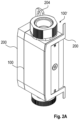
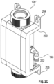
- Figs. 2A to 2C show diagrams of a connection element 200 or bracket 200 in different views.
- the connection element 200 or bracket 200 holds two modular flowcell units such as modular flowcell units 100, 100', 100" shown in Figs. 3 and 4 , together.
- the bracket 200 is shown in a cut view.
- the modular flowcell unit 100' is shown in a side view.
- Fig. 2C shows a spigot 148 or tap 148 mounted at a modular flowcell unit 100" that might be a modular end cell at which no further modular flowcell unit will be connected.
- the bracket 200 has a shape that is complementary to the protruding edges 146 and the gaps 106 of the three sides of two adjacent flowcell units 100, 100', 100", whose outer surfaces of their plate 140 lay side by side. That is, the bracket 200 has an essentially rectangular U-shape with a slot 202 running along the inner side of the "U".
- the slot 202 receives the protruding edges 146 of the two adjacent plates 140 of two flowcell units 100, 100', and 100". From view of the flowcell units 100, 100', 100", the gaps 106 of the two adjacent plates 140 receive the edges forming the slot 202 of the bracket 200.
- the slots 202 in the bracket 200 allow to slide the bracket over the features on the module 100, 100', 100" to hold two modules 100, 100', 100" together.
- the bracket 200 has a plate 204, 206 such that the bracket 200 can rest against a wall.
- the plate 204 of at least one side has a hole, for example a keyhole-shaped mounting hole for mounting the bracket 200 with a screw or a hook at the wall.
- the keyhole shaped mounting hole the flowcell unit 100, 100', and 100" can be attached and removed from the wall without any tools.
- the bracket 200 may have a retention feature on bottom of bracket 200 to let the user know when the bracket 200 is fitted correctly.
- the retention feature 206 may be realized by a latching mechanism that ensures the correct fitting of the bracket 200 on the plate 140.
- the latching mechanism consists of protrusions at the edge between plate and the body of the bracket 200 where the non-protruding edge of plate 140 at gap 106 can snap in, forming a fastening clip.
- a more preferred retention feature is shown in Figs. 2B , and 6 to 8 .
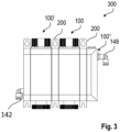
- Fig. 3 shows a diagram of a flowcell assembly 300 where two modular flowcell units 100, 100' are attached to each other using the fastening clip/bracket 200 as illustrated in Figs. 2A to 2C and spigots 142, 148 at the sides.
- the connections and interfaces between the flowcell units 100 and 100' are shown in Figs. 4 and 5 .
- the modular flowcell unit 100' on the left in Fig.3 may be a flow control module 100'.
- This module 100' is designed to assist the user in controlling the flowrate passing through the flowcell(s). It may made of the following devices and functionalities: Sample inlet 142, a grab sample port for taking a sample for sensor calibration, a control valve, for example a needle valve for fine control over flowrate, an out of sample float switch for indicating to the user if the flowrate is too low; and sample outlet 144 and spigot 148.
- the modular flowcell unit 100 on the right may be a sensor module. It allows fitting of any sensor that is contained within the %" sensor body.
- the sensors may be pH-, ORP-, Chlorine-, Dissolved Oxygen-, or other sensors.
- Fig. 4 shows diagram of a flowcell assembly 400 where three modular flowcell units 100, 100', 100" are attached to each other, again using the bracket 200 described above. In the middle, there are two units 100, 100' as described above, which are connected in series using the mechanical interface 200 and the fluid interface 402, that is, the spigot system 402.
- the outer flowcell units are a flow control unit 100', and a further unit 100", depicted with an outlet near the top.
- a further unit 100" may be, for example, a pump module, a valve module, a filtration module, an energy harvesting module, a chlorine zero calibration module, a verification module, or a temperature control module, which have been described above.
- the modular flowcell units 100 are also modules that have top 404 and bottom 406 plugs.
- the bottom plug 406 can either just be blocked off as shown in Fig. 4 , or a stirrer module could be fitted. Further plugs may be fitted.
- the top plug 404 allows the %" sensor to be fitted, but can also be modified to allow different sized sensors to fit, such as a PG13.5 pH sensor.
- Fig. 5 shows a diagram of the fluid interface 402 of depicted in Fig. 4 in more detail.
- the fluid interface 402 is realized as a spigot system 402, which is placed between the sections of two modular flowcell units 100, 100', 100".
- This spigot 148 contains a seal 502 onto both modules that are being connected together.
- This seal 502 is arranged such that pressure within the system 402 does not cause the modular flowcell units 100, 100', 100" to push each other apart, so the brackets 200 do not need to apply any compression to the system.
- Figs. 6 , 7A , 7B and 8 show embodiments with a spring-loaded pin 600 or spring plunger 600 for retaining the bracket 200.
- Fig. 8 shows a part of a bracket 200, which is the connection element that connects two modular flowcell units with each other.
- the bracket 200 is U-shaped and has a groove 808 on each of the opposite sides.
- Fig. 6 shows a sectional view at the plane that intersects the spring-loaded pins 600.
- the spring-loaded pins 600 are inserted in the gap or groove 106 of plate 140.
- the plate 140 may be separate from or integral with the housing 102. Further, the plate 140 may form one side of the housing 102, i.e. be a part of the housing 102.
- the bracket 200 is pulled over the protruding edge 146 of the plate 140.
- the spring-loaded pin 600 comprises an elastic element such as a spring (not shown in Fig. 6 ) that pushes a ball 602 out of the groove 106.
- the bracket sticks the plates 140 or sides of the housings 102 at least at two edges, e.g. the top and bottom edges, preferably at three edges, e.g. additionally the front edge, together.
- the bracket 200 pushes the ball 602 of the spring-loaded pin 600 down until the grooves 808 in the bracket 200 reach the position of the spring-loaded pins 600.
- the ball of the spring plunger 600 is pressed into the groove by the preload of the spring and retains the bracket 200 at this position.
- elements with another shape could be used.
- the elements can, for example, be cuboid-shaped and have rounded or flattened edges so that the element can slip into the groove and also slip out of the groove when the clamp is removed. The inclination of the edges can be different so that the element can slide in easily but can only be removed again with a certain amount of force.
- Fig. 7B shows an oblique top view of the spring plunger 600 embedded in the groove 106 of the plate or the gap 106 of the housing 102.
- the spring plungers 600 are arranged in every modular flowcell unit, i.e. in all flowcell regulator and end cell sections.
- Fig. 7A shows a diagram of the mounted connection element in a side view and the spring-loaded pin.
- the reference numbers for the elements correspond to the reference numbers of the previous figures.
Landscapes
- Chemical & Material Sciences (AREA)
- Life Sciences & Earth Sciences (AREA)
- Health & Medical Sciences (AREA)
- Physics & Mathematics (AREA)
- General Physics & Mathematics (AREA)
- Pathology (AREA)
- Analytical Chemistry (AREA)
- Biochemistry (AREA)
- General Health & Medical Sciences (AREA)
- Immunology (AREA)
- Medicinal Chemistry (AREA)
- Food Science & Technology (AREA)
- Engineering & Computer Science (AREA)
- Dispersion Chemistry (AREA)
- Fluid Mechanics (AREA)
- Optical Measuring Cells (AREA)
- Sampling And Sample Adjustment (AREA)
Abstract
Description
- The invention relates to a modular flowcell unit, a flowcell assembly, and the use of a modular flowcell unit.
- Flowcells are used for mounting specific sensors and controlling the flowrate by a flow controller. Usually, flowcells are specialized to individual sensor parameters. It is difficult to find a flowcell that is compatible with multiple sensor types. Use of a single flowcell design for multiple sensor variants allows simplified manufacturing, fewer variants and cost reduction.
- There may be a desire to provide an improved flowcell.
- The problem is solved by the subject-matter of the independent claims. Embodiments are provided by the dependent claims, the following description and the accompanying figures.
- The described embodiments similarly pertain to the modular flowcell unit and the flowcell assembly. Synergetic effects may arise from different combinations of the embodiments although they might not be described in detail. It shall be noted that all embodiments of the present invention concerning a method, might be carried out with the order of the steps as described, nevertheless this has not to be the only and essential order of the steps of the method. The herein presented methods can be carried out in another order of the disclosed steps without departing from the respective method embodiment, unless explicitly mentioned to the contrary hereinafter.
- Technical terms are used by their common sense. If a specific meaning is conveyed to certain terms, definitions of terms will be given in the following in the context of which the terms are used.
- According to a first aspect, a modular flowcell unit is provided. The modular flowcell unit comprises a mechanical fixing interface configured for receiving a further modular flowcell unit, and a fluid interface configured for receiving fluid from the further modular flowcell unit or for transferring fluid to the further modular flowcell unit.
- In other words, the modular flowcell unit is a single unit intended to being connected to at least one further modular flowcell unit. For that, it comprises a mechanical fixing interface, e.g. on one side or on two sides of the flowcell unit. However, the modular flowcell unit may also be used stand-alone, if the functionality of the further modules is not required. In order to be modular, it is required that each modular unit can be flowed through by the fluid, herein also called "sample". This means that the fluid can be passed from one modular unit to another modular unit, the fluid can flow through this unit and be passed to yet another modular unit, etc., so that a chain of modular units can be formed. Two connections are necessary to couple the units. The first concerns the attachment of the units to each other and the second concerns the connection of the flow. The two connections are interrelated because the fixing must ensure the flow of the liquid, and that the whole arrangement, especially the flow connection, is mechanically stable. A further connection might optionally be an electric connection, where "electric" may mean power, data, control signals, etc. Some of the electric connections may be achieved by a wireless connection.
- The modular flowcell units may be used in isolation. The design allows individual cells to be mounted directly to fluid hoses. In this case, the brackets are not used to attach the modular flowcell unit to the side of other components, but only to attach the modular flowcell unit to the customer's wall, bracket, or panel, etc.
- The modular flowcell units may also be used with other modular flowcell units, end cells, that is, modular flowcell units that have a fluid interface or spigot for connecting to another modular flowcell unit only on one side, or regulators using the spigot part as an intermediary fluid connection.
- According to an embodiment, the mechanical fixing interface comprises a lateral plate enclosed with a protruding edge into which a connection element can be inserted.
- The connection element may be for example a bracket. "Lateral" addresses those sides of the flowcell unit where the inlet and/or the outlet for the fluid is located. The inlet and the outlet may be located at opposite sides, although this is not a requirement. For example, the outlet side may be located at the side adjacent to the inlet side, which form a 90° angle. In case of lateral inlet and outlet sides, these sides may also be denominated "left" and "right" sides from view of a front side. "Backside" may be defined to be the side facing to a wall to which the flowcell unit may be mounted, and the front side is then consequently the remaining side opposite to the backside. The plates may be located at the left and/or right sides, where the further modular flowcell units can be attached to the modular flowcell unit. The outer surface of a plate may be longer and/or wider than the main body of the plates such that protruding edges are formed. The adjacent edges of the flowcell unit and a further flowcell unit to be connected to the flowcell unit may then form a common pair of edges. A bracket having a longitudinal slot can be moved over this pair of edges such that the pair of edges slips into the slot. In this way, the edges are kept together and the flowcell units are fixed to each other. Other fixing arrangements may be applied. This bracket/plate can then be used to mount the joined units to a wall or other bracket. Other mounting arrangements and locations may be applied. The plates may be formed by the housing. That is, the plates may be integral with the housing and a part of the housing, such that they form the wall of the modular flowcell unit. The plate or the wall are therefore configured for laterally abutting with a further modular flowcell unit if the further modular flowcell unit is received by the mechanical fixing interface.
- According to an embodiment, one of the narrow sides, i.e., circumferential sides, of the plate or the wall comprises a spring-loaded pin for fixing a connection element to the modular flowcell unit. The narrow side may have a groove or a gap, in which the spring-loaded pin is embedded.
- The connection element may be a bracket as described above. The spring-loaded pin or spring plunger may comprise a lock element such as the pin itself, a ball-like element, a cuboid-shaped element or another suitable element, which is pressed against the force of the spring into the groove or gap at one of the narrow sides of the plate when the connection element is moved over the protruding edges. At a position of the connection element, where the groove of the connection element faces the spring-loaded pin , the lock element is pressed by the force of the spring into the groove of the connection element such that the connection element is removable locked. Preferably, there are spring-loaded pin s on opposite sides of the narrow sides of the plate, e.g. a top side and a bottom side.
- According to an embodiment, the modular flowcell unit further comprises a sample inlet configured to be connectable to a sample outlet of a further modular flowcell unit and a sample outlet configured to be connectable to a sample inlet of a further modular flowcell unit, and/or an electrical interface to a further modular flowcell unit.
- The sample inlet may receive the sample either from another modular flowcell unit or from an external source. In order to receive the sample from another modular flowcell unit, it has to be connectable to the outlet of another modular flowcell unit. Accordingly, the sample outlet outputs the sample either to another modular flowcell unit or to an external sink.
- The inlets and outlets may therefore be arranged at such heights or locations that a chain can be built. The fluid can pass from one to another flowcell unit, and also through these units to further units. If a flowcell requires the inlet and outlet to be at different heights, the cells may be constructed such that an inlet may be used also as outlet and vice versa. For example, two identical cells can be connected by turning one of the cells by 180° such that, from a front view, the left and backside of the second cell, turns to be the right and the front side. Then, the outlet of the first cell is on the same height as the inlet of the second cell, or vice versa.
- Alternatively, or in addition, the cells may have a plurality of inlets/outlets on one side, which can be used as required by an application. Further, a specialized flowcell unit may have inlets or outlets at individual heights.
- Furthermore, a flowcell unit may be designed to be a modular end cell, which is connectable only on one side to another modular flowcell unit.
- Moreover, the flowcell unit may comprise an electrical interface to a further modular flowcell unit. The electrical interface may provide control lines for control signals, data lines and/or power lines.
- According to an embodiment, the modular flowcell unit is a sensor flowcell unit, herein also referred to as "sensor module" comprising a fitting that is configured to receive a sensor.
- The sensor flowcell unit is therefore not only modular with respect to further flowcell units but also with respect to its sensor functionality. For example, the sensor flowcell unit may comprise only a fitting for a sensor not including the sensor. The sensor can be installed later. The fitting is independent on the type of sensor to be fitted so that different types of sensors may be received by such a universal fitting. However, the sensor may be already integrated into the fitting when assembling the flowcell module and therefore be part of the sensor flowcell unit.
- There may be different sensor flowcell units for different sensor body size categories or shape categories.
- According to an embodiment, the sensor flowcell unit comprises a sensor for sensing one of: a pH concentration, an oxidation-reduction potential (ORP), a chlorine concentration, or a dissolved oxygen concentration.
- The fitting allows, for example, receiving any sensor that is contained within a %"-sized fitting or "sensor body". For example, pH-, ORP-, chlorine-, and dissolved oxygen-sensors as well as other sensors are suitable for such a fitting.
- According to an embodiment, the modular flowcell unit is a flow control module comprising a flow control arrangement or a sensor module.
- In other words, the modular design makes it possible to separate the flow control from the sensor system and thus integrate a number of functions into this flow cell. The flow control module indicates as an example such specialization for the flow control functions. Nevertheless, also in the sensor module further functionalities may be integrated.
- According to an embodiment, the flow control arrangement comprises a needle valve, a grab sample port and/or an out-of-sample float switch.
- The needle valve may be used for fine controlling the flowrate. The grab sample port may be used for taking a sample for sensor calibration, and the out-of-sample float switch may be used, for example, for indicating to the user if the flowrate is too low.
- That is, due to the modular design, there exists much more room for adding functionalities to the flow control arrangement. It is possible to integrate these functional arrangements into a single module, and it is further possible to have only one or two of these functional arrangements in the modular flowcell unit. This allows having the respective remaining functional arrangements in further modular flowcell units, which may be connected to the flowcell unit only if required.
- As already described, each modular flowcell unit has a sample inlet and a sample outlet, which therefore applies also to the modular flowcell unit with the flow control arrangement.
- According to an embodiment, the modular flowcell unit is one of
- a pump unit configured to add additional chemicals into the fluid, mixing of such chemicals, and/or monitor fluid usage,
- a valve unit configured to control valves, i.e., for example to open or close valves,
- a filtration unit configured to filtrate the fluid and/or to perform filter diagnostic functions,
- an energy harvesting unit configured to generate electricity from the sample flow,
- a chlorine zero calibration unit configured to remove chlorine from the fluid for calibrating a chlorine sensor,
- a verification unit configured to calibrate and check an optical sensor, and
- a temperature control unit configured to control the temperature of the sample flowing through the flowcell.
- A pump unit could be envisaged where a pump is used to add additional chemicals into the flowing system. For example, cleaning solutions may be added automatically to perform chemical cleaning of the sensors and flowcell to stop the build-up of contaminants. In another example, buffer chemicals may be added to control the pH value of the solution flowing through the flowcell to obtain more stable readings for parameters that are pH sensitive. In a further example, calibration chemicals may be added to automatically pump in a calibration standard and perform a sensor calibration without operator input. This unit could also perform the mixing of such chemicals, and perform a monitoring of fluid usage etc.
- A valve unit could be envisaged that could allow the system to control which valves are to be open or closed. This could be used to allow for multiple sample lines to be sampled by a single set of sensors. For that, the valve unit my comprise more than one inlet, to which sample lines are connected, and which are led to one or more than one outlet. Each sample line may have a valve that may be controlled by a controller to open or close the line. The valve unit could also be used in conjunction with the pump module to allow for pumping a variety of different chemicals, for example to perform multi point calibrations.
- A filtration unit could allow the system to be used with samples that contain a higher particulate load. The filtration unit could be self-cleaning with backflush capability, and could also have diagnostics telling the user when to replace the filter and/or clean the filter etc.
- An energy harvesting unit containing a small turbine could generate electricity from the sample flow. The generated energy could be used, for example, for powering low power electrochemical sensors such as pH- or chlorine-sensors or for other low power applications such as wireless low power communication.
- A zero chlorine calibration unit can be used to perform zero chlorine calibrations by switching the flow to pass through a carbon filter. This removes all chlorine from the sample, so that a zero chlorine calibration can be performed by the sensor. This functionality could be incorporated into a special flowcell unit so that external parts would not be required.
- Regarding the verification unit, some optical sensors can be calibrated and/or checked with solid standards. A modular flowcell unit could be created that automatically moves these solid standards into the optical path of the optical sensor, so allowing for an automatic check of functionality of these types of sensors. The verification functionality may be realized by a linear actuator and an optical standard for performing the checks.
- Further, the modular flowcell unit could be a temperature control unit that controls the temperature of the sample flowing through the flowcell. The temperature control unit could be used for processes with rapidly changing temperatures, and for sensors that are sensitive to changes in process temperature. It could also be used if the chemicals being measured are not measurable without some form of temperature controlled digestion stage.
- According to a further aspect, a flowcell assembly is provided that comprises a first modular flowcell unit as described herein and a second modular flowcell unit as described herein. The first modular flowcell unit and the second modular flowcell unit are connectable to each other for providing a common flow of a sample through the first modular flowcell unit and the second modular flowcell.
- In other words, the flowcell may be assembled of two modular parts, herein referred to as "modular flowcell units" that are connected to each other. Each part may provide a different functionality. However, they may also provide the same or similar functionalities such as a sensor functionality with different sensors. The flowcell assembly comprises such a combination. In an example, the first modular flowcell unit is a sensor flowcell unit and the second modular flowcell unit is a flow control unit or another modular flowcell unit as described herein.
- According to an embodiment, the flowcell assembly comprises a connection element, for example a bracket, configured to mechanically fix two cells together.
- The connection element or bracket holds two adjacent cell units together and ensures that the inlet/outlet connections do not break.
- According to an embodiment, the connection element is a U-shaped bracket, comprising grooves for receiving the protruding edges of the plates of the first and second modular flowcell units, and grooves, recesses or holes on opposite sides of the "U" for receiving load springs.
- The connection element consist of U-shaped rectangular bars with a continuous slot into which the protruding edges of the plates are moved. The groove or recesses for the spring-loaded pin are located on the walls of the slot, and are for example transverse to the slot. Alternatively instead of grooves or recesses, the bars may comprise holes to receive the spring-loaded pins.
- Alternatively, the flowcell assembly comprises a fastening clip. The fastening clip may be arranged on the end sides, i.e., the outer sides of the outer units where no further cell is attached to so that the utmost right and left units are securely fixed.
- The connection element may further have a keyhole shaped mounting hole for attaching removable the flowcell arrangement to a wall. That is, the flowcell arrangement can be attached and removed from the wall without any tools. The keyhole shaped mounting hole, allows a simple mounting of the complete flowcell arrangement to, for example, a wall.
- According to an embodiment, the connection element comprises a slot allowing the connection element to slide over the mechanical fixing interface to hold two flow control units together. For example, the plates comprise protruding edges on their outer sides that fit into the slots, on two adjacent flow control units.
- The flowcell assembly may further comprise a control unit for controlling electronic and electro mechanic parts.
- The control unit may also be a modular flowcell unit, or it may be integrated into a modular flowcell unit with further functionalities. In further embodiments, it may be located external to the modular flowcell units. For example, it could be an application on a computer, a smart phone, a tablet, or it could be a dedicated control device. The control unit may further comprise a human-machine interface with a display and/or keypad or other input/output devices for use by an operator. Further, it may comprise a control interface, interfacing the flowcell units for sending control signals and/or for receiving, for example, status signals or monitoring signals. The control unit may alternatively located, for example, within the sensor flowcell unit, which may be seen as a central unit. Further, under the term "control unit" may be understood - not necessarily but also - the totality of sub-control units, where a sub-control unit may be a controller for valves or other actuators, for a display, for a power switch, for a communication device, etc.
- According to a further aspect, a use of a flowcell unit as a modular flowcell unit is provided.
- Exemplary embodiments of the invention will be described in the following with reference to the following drawings.
-
-
Fig. 1 shows a diagram of a modular flowcell unit. -
Figs. 2A to 2C show diagrams of a modular flowcell unit with a connection element in different views. -
Fig. 3 shows a diagram of a flowcell assembly with two modular flowcell units. -
Fig. 4 shows a diagram of a flowcell assembly with three modular flowcell units. -
Fig. 5 shows a diagram of the fluid interface. -
Fig. 6 shows a diagram of the mounted connection element. -
Figs. 7A and 7B show diagrams of the spring-loaded pin. -
Figs. 8 show a diagram of the connection element. - The figures are merely schematic representations and serve only to illustrate embodiments of the invention. Identical or equivalent elements are in principle provided with the same reference signs.
-
Fig. 1 shows a diagram of amodular flowcell unit 100 with aninlet 142 and anoutlet 144, a fitting 104 orsensor housing 104, and apipe 156. Theflowcell unit 100 further has ahousing 102 at which afastening arrangement 140 as an example of themechanical fixing interface 140 is disposed. Theinlet 142 and theoutlet 144 each have afluid interface 148 for receiving fluid from the further module flowcell unit as shown inFig. 2C , andFigs. 3 to 5 , or for transferring fluid to the further module flowcell unit. - The
mechanical fixing interface 140 consists of a plate with a cuboid shape, which has protrudingedges 146 at for example three sides, e.g. a front side and a top and bottom side. The front side is a side parallel to the longitudinal axis of thesensor housing 102 or thepipe 156, and the top or bottom sides are the sides adjacent to the front side. A distinction between the orientations "top" and "bottom" is not necessary here. The protruding edges 146 may also be present on the fourth side. The protruding edges 140 are located at the outer surface of the cuboid, such that agap 106 is formed between the protrudingedges 146 and thehousing 102 of theflowcell unit edge 146 and thegap 106 serve for receiving afastening clip 200 orbracket 200 as shown inFig. 2 . The top and bottom sides, where, for example, the protrudingedge 146 and thegap 106 are located, and the front side and rear side are referred to as "narrow sides" or circumferential sides of the plate in this disclosure. -
Figs. 2A to 2C show diagrams of aconnection element 200 orbracket 200 in different views. Theconnection element 200 orbracket 200 holds two modular flowcell units such asmodular flowcell units Figs. 3 and4 , together. InFig. 2A , thebracket 200 is shown in a cut view. InFig. 2B , the modular flowcell unit 100' is shown in a side view.Fig. 2C shows aspigot 148 or tap 148 mounted at amodular flowcell unit 100" that might be a modular end cell at which no further modular flowcell unit will be connected. Thebracket 200 has a shape that is complementary to the protrudingedges 146 and thegaps 106 of the three sides of twoadjacent flowcell units plate 140 lay side by side. That is, thebracket 200 has an essentially rectangular U-shape with aslot 202 running along the inner side of the "U". Theslot 202 receives the protrudingedges 146 of the twoadjacent plates 140 of twoflowcell units flowcell units gaps 106 of the twoadjacent plates 140 receive the edges forming theslot 202 of thebracket 200. Thus, theslots 202 in thebracket 200 allow to slide the bracket over the features on themodule modules - At both end sides, the
bracket 200 has aplate bracket 200 can rest against a wall. Theplate 204 of at least one side has a hole, for example a keyhole-shaped mounting hole for mounting thebracket 200 with a screw or a hook at the wall. Especially, by the keyhole shaped mounting hole, theflowcell unit - On at least one side, the
bracket 200 may have a retention feature on bottom ofbracket 200 to let the user know when thebracket 200 is fitted correctly. Theretention feature 206 may be realized by a latching mechanism that ensures the correct fitting of thebracket 200 on theplate 140. For example, the latching mechanism consists of protrusions at the edge between plate and the body of thebracket 200 where the non-protruding edge ofplate 140 atgap 106 can snap in, forming a fastening clip. A more preferred retention feature is shown inFigs. 2B , and6 to 8 . -
Fig. 3 shows a diagram of aflowcell assembly 300 where twomodular flowcell units 100, 100' are attached to each other using the fastening clip/bracket 200 as illustrated inFigs. 2A to 2C andspigots flowcell units 100 and 100' are shown inFigs. 4 and5 . - The modular flowcell unit 100' on the left in
Fig.3 may be a flow control module 100'. This module 100' is designed to assist the user in controlling the flowrate passing through the flowcell(s). It may made of the following devices and functionalities:Sample inlet 142, a grab sample port for taking a sample for sensor calibration, a control valve, for example a needle valve for fine control over flowrate, an out of sample float switch for indicating to the user if the flowrate is too low; andsample outlet 144 andspigot 148. - The
modular flowcell unit 100 on the right may be a sensor module. It allows fitting of any sensor that is contained within the %" sensor body. The sensors may be pH-, ORP-, Chlorine-, Dissolved Oxygen-, or other sensors. -
Fig. 4 shows diagram of a flowcell assembly 400 where threemodular flowcell units bracket 200 described above. In the middle, there are twounits 100, 100' as described above, which are connected in series using themechanical interface 200 and thefluid interface 402, that is, thespigot system 402. The outer flowcell units are a flow control unit 100', and afurther unit 100", depicted with an outlet near the top. Such afurther unit 100" may be, for example, a pump module, a valve module, a filtration module, an energy harvesting module, a chlorine zero calibration module, a verification module, or a temperature control module, which have been described above. - The
modular flowcell units 100 are also modules that have top 404 and bottom 406 plugs. Thebottom plug 406 can either just be blocked off as shown inFig. 4 , or a stirrer module could be fitted. Further plugs may be fitted. Thetop plug 404 allows the %" sensor to be fitted, but can also be modified to allow different sized sensors to fit, such as a PG13.5 pH sensor. -
Fig. 5 shows a diagram of thefluid interface 402 of depicted inFig. 4 in more detail. Thefluid interface 402 is realized as aspigot system 402, which is placed between the sections of twomodular flowcell units spigot 148 contains aseal 502 onto both modules that are being connected together. Thisseal 502 is arranged such that pressure within thesystem 402 does not cause themodular flowcell units brackets 200 do not need to apply any compression to the system. -
Figs. 6 ,7A ,7B and8 show embodiments with a spring-loadedpin 600 orspring plunger 600 for retaining thebracket 200.Fig. 8 shows a part of abracket 200, which is the connection element that connects two modular flowcell units with each other. Thebracket 200 is U-shaped and has agroove 808 on each of the opposite sides.Fig. 6 shows a sectional view at the plane that intersects the spring-loadedpins 600. The spring-loadedpins 600 are inserted in the gap or groove 106 ofplate 140. Theplate 140 may be separate from or integral with thehousing 102. Further, theplate 140 may form one side of thehousing 102, i.e. be a part of thehousing 102. InFig. 6 , thebracket 200 is pulled over the protrudingedge 146 of theplate 140. The spring-loadedpin 600 comprises an elastic element such as a spring (not shown inFig. 6 ) that pushes aball 602 out of thegroove 106. The bracket sticks theplates 140 or sides of thehousings 102 at least at two edges, e.g. the top and bottom edges, preferably at three edges, e.g. additionally the front edge, together. When slipping the bracket from the front side over the top and bottom edges, thebracket 200 pushes theball 602 of the spring-loadedpin 600 down until thegrooves 808 in thebracket 200 reach the position of the spring-loadedpins 600. At this position, the ball of thespring plunger 600 is pressed into the groove by the preload of the spring and retains thebracket 200 at this position. Instead of a ball, elements with another shape could be used. The elements can, for example, be cuboid-shaped and have rounded or flattened edges so that the element can slip into the groove and also slip out of the groove when the clamp is removed. The inclination of the edges can be different so that the element can slide in easily but can only be removed again with a certain amount of force. -
Fig. 7B shows an oblique top view of thespring plunger 600 embedded in thegroove 106 of the plate or thegap 106 of thehousing 102. The spring plungers 600 are arranged in every modular flowcell unit, i.e. in all flowcell regulator and end cell sections.Fig. 7A shows a diagram of the mounted connection element in a side view and the spring-loaded pin. The reference numbers for the elements correspond to the reference numbers of the previous figures. - Other variations to the disclosed embodiments can be understood and effected by those skilled in the art in practicing the claimed invention, from the study of the drawings, the disclosure, and the appended claims. In the claims, the word "comprising" does not exclude other elements or steps and the indefinite article "a" or "an" does not exclude a plurality. A single processor or other unit may fulfill the functions of several items or steps recited in the claims. The mere fact that certain measures are recited in mutually different dependent claims does not indicate that a combination of these measures cannot be used to advantage. Any reference signs in the claims should not be construed as limiting the scope of the claims.
-
- 100, 100', 100"
- modular flowcell units
- 102
- housing of the modular flowcell unit
- 104
- fitting, sensor housing
- 106
- gap/groove between the housing of the modular flowcell unit and the protruding
edge 146 of theplate 140 - 140
- mechanical fixing interface, lateral plate
- 142
- sample inlet
- 144
- sample outlet
- 146
- protruding edge of the plate
- 148
- fluid interface, spigot
- 156
- pipe connecting the inlet with the outlet
- 200
- connection element, fastening clip, bracket
- 202
- slot/groove of the bracket
- 204
- (plate with) keyhole-shaped mounting hole
- 206
- latching mechanism, retention feature
- 300
- flowcell assembly
- 402
- fluid interface / spigot system
- 404
- top plug
- 406
- bottom plug
- 502
- seals of the spigots
- 600
- spring-loaded pin
- 602
- ball
- 808
- groove in bracket
Claims (15)
- Modular flowcell unit (100, 100', 100") comprisinga mechanical fixing interface (140) configured for receiving a further modular flowcell unit (100, 100', 100"); anda fluid interface configured for receiving fluid from the further modular flowcell unit (100, 100', 100") or for transferring fluid to the further modular flowcell unit (100, 100', 100").
- Modular flowcell unit (100, 100', 100") according to claim 1, wherein the mechanical fixing interface (140) comprises a lateral plate (140) enclosed with a protruding edge (146) into which a connection element (200) can be inserted.
- Modular flowcell unit (100, 100', 100") according to claim 1 or 2, wherein one of the narrow sides of the lateral plate (140) comprises a spring-loaded pin (600) for fixing a connection element (200) to the modular flowcell unit (100, 100', 100").
- Modular flowcell unit (100, 100', 100") according to any one of the previous claims, wherein the modular flowcell unit (100, 100', 100") further comprises a sample inlet configured to be connectable to a sample outlet of a further modular flowcell unit (100, 100', 100") and a sample outlet configured to be connectable to a sample inlet of a further modular flowcell unit (100, 100', 100"), and/or an electrical interface to a further modular flowcell unit (100, 100', 100").
- Modular flowcell unit (100, 100', 100") according to any one of the previous claims, wherein the modular flowcell unit (100, 100', 100") is a sensor flowcell unit (100, 100', 100") comprising a fitting that is configured to receive a sensor.
- Modular flowcell unit (100, 100', 100") according to the previous claim, wherein the sensor flowcell unit (100, 100', 100") comprises a sensor for sensing one of: a pH concentration, an Oxidation-Reduction Potential, a chlorine concentration, or a dissolved oxygen concentration.
- Modular flowcell unit (100, 100', 100") according to any one of the previous claims, wherein the modular flowcell unit (100, 100', 100") is a flow control module comprising a flow control arrangement or a sensor module.
- Modular flowcell unit (100, 100', 100") according to the previous claim, wherein the flow control arrangement comprisesa control valve;a grab sample port; and/oran out-of-sample float switch.
- Modular flowcell unit (100, 100', 100") according to any one of the previous claims, wherein the modular flowcell unit (100, 100', 100") is one ofa pump unit configured to add additional chemicals into the fluid, mixing of such chemicals, and/or monitor fluid usage;a valve unit configured to control valves;a filtration unit configured to filtrate the fluid and/or to perform filter diagnostic functions;an energy harvesting unit configured to generate electricity from the sample flow; a chlorine zero calibration unit configured to remove chlorine from the fluid for calibrating a chlorine sensor;a verification unit configured to calibrate and check an optical sensor; anda temperature control unit configured to control the temperature of the sample flowing through the modular flowcell unit (100, 100', 100").
- Flowcell assembly (300), comprising a first modular flowcell unit (100, 100', 100") according to any of claims 1-8 and a second modular flowcell unit (100, 100', 100") according to any of claims 1-9; wherein
the first modular flowcell unit (100, 100', 100") and the second modular flowcell unit (100, 100', 100") are connectable to each other for providing a common flow of a sample through the first modular flowcell unit (100, 100', 100") and the second modular flowcell (100, 100', 100"). - Flowcell assembly (300) according to claim 9 or 10, wherein the flowcell assembly (300) comprises a connection element (200) for mechanically fixing two modular flowcell units (100, 100', 100") together.
- Flowcell assembly (300) according to claim 11, wherein the connection element (200) is a U-shaped bracket, comprising grooves for receiving the protruding edges (146) of the plates (140) of the first and second modular flowcell units (100, 100', 100"), and grooves (808), recesses or holes on opposite sides of the "U" for receiving load springs.
- Flowcell assembly (300) according to claim 11 or 12, wherein the connection element (200) has a keyhole shaped mounting hole (204) for attaching removable the flowcell assembly (300) to a wall.
- Flowcell assembly (300) according to any of claims 11 to 13, wherein the connection element (200) comprises a slot allowing the connection element (200) to slide over the mechanical fixing interface (140) of two adjacent flow control units to hold two modular flowcell units (100, 100', 100") together.
- Use of a spring load for fastening a connection element (200) when fixing two modular flowcell units (100, 100', 100") together.
Priority Applications (3)
| Application Number | Priority Date | Filing Date | Title |
|---|---|---|---|
| EP23151833.3A EP4400815A1 (en) | 2023-01-16 | 2023-01-16 | Modular flowcell unit and flowcell assembly |
| CN202410055016.6A CN118348196A (en) | 2023-01-16 | 2024-01-15 | Modular flow cell unit and flow cell assembly |
| US18/413,440 US20240241034A1 (en) | 2023-01-16 | 2024-01-16 | Modular Flowcell Unit and Flowcell Assembly |
Applications Claiming Priority (1)
| Application Number | Priority Date | Filing Date | Title |
|---|---|---|---|
| EP23151833.3A EP4400815A1 (en) | 2023-01-16 | 2023-01-16 | Modular flowcell unit and flowcell assembly |
Publications (1)
| Publication Number | Publication Date |
|---|---|
| EP4400815A1 true EP4400815A1 (en) | 2024-07-17 |
Family
ID=84981432
Family Applications (1)
| Application Number | Title | Priority Date | Filing Date |
|---|---|---|---|
| EP23151833.3A Pending EP4400815A1 (en) | 2023-01-16 | 2023-01-16 | Modular flowcell unit and flowcell assembly |
Country Status (3)
| Country | Link |
|---|---|
| US (1) | US20240241034A1 (en) |
| EP (1) | EP4400815A1 (en) |
| CN (1) | CN118348196A (en) |
Citations (4)
| Publication number | Priority date | Publication date | Assignee | Title |
|---|---|---|---|---|
| CN207351949U (en) * | 2017-08-28 | 2018-05-11 | 广州商辉怡业计算机科技有限公司 | A kind of integrated form flow cell module |
| DE102018132453A1 (en) * | 2018-12-17 | 2020-06-18 | Endress+Hauser Conducta Gmbh+Co. Kg | Flow measuring cell and arrangement comprising several flow measuring cells |
| CA3200697A1 (en) * | 2020-11-23 | 2022-05-27 | Johannes Gutenberg-Universitat Mainz | Microfluidic flow cell and system for analyzing or diagnosing biofilms and cell cultures, and the use thereof |
| US11366053B2 (en) * | 2018-12-04 | 2022-06-21 | Endress+Hauser Conducta Gmbh+Co. Kg | Flow-through measuring station |
Family Cites Families (1)
| Publication number | Priority date | Publication date | Assignee | Title |
|---|---|---|---|---|
| CA320067A (en) * | 1932-03-01 | W. Edwards George | Mower reel |
-
2023
- 2023-01-16 EP EP23151833.3A patent/EP4400815A1/en active Pending
-
2024
- 2024-01-15 CN CN202410055016.6A patent/CN118348196A/en active Pending
- 2024-01-16 US US18/413,440 patent/US20240241034A1/en active Pending
Patent Citations (4)
| Publication number | Priority date | Publication date | Assignee | Title |
|---|---|---|---|---|
| CN207351949U (en) * | 2017-08-28 | 2018-05-11 | 广州商辉怡业计算机科技有限公司 | A kind of integrated form flow cell module |
| US11366053B2 (en) * | 2018-12-04 | 2022-06-21 | Endress+Hauser Conducta Gmbh+Co. Kg | Flow-through measuring station |
| DE102018132453A1 (en) * | 2018-12-17 | 2020-06-18 | Endress+Hauser Conducta Gmbh+Co. Kg | Flow measuring cell and arrangement comprising several flow measuring cells |
| CA3200697A1 (en) * | 2020-11-23 | 2022-05-27 | Johannes Gutenberg-Universitat Mainz | Microfluidic flow cell and system for analyzing or diagnosing biofilms and cell cultures, and the use thereof |
Also Published As
| Publication number | Publication date |
|---|---|
| CN118348196A (en) | 2024-07-16 |
| US20240241034A1 (en) | 2024-07-18 |
Similar Documents
| Publication | Publication Date | Title |
|---|---|---|
| US6938506B2 (en) | Sensor head apparatus | |
| US7138926B2 (en) | Sensor head component | |
| US10393553B2 (en) | Modular sensor system | |
| US6701962B2 (en) | Stackable valve manifold arrangement | |
| US6798347B2 (en) | Sensor head component | |
| EP3747543A1 (en) | Modular fluidic chip and fluidic flow system comprising same | |
| US20040079148A1 (en) | Single-body multiple sensing device | |
| US20030145646A1 (en) | Multi-parameter monitoring system | |
| JP2014530363A (en) | Modular dual-compartment temperature transmitter | |
| CN120468225A (en) | Detection components and blood gas analysis systems | |
| US6780064B2 (en) | Modular analytical system having at least two modules connected by a connecting plug | |
| US11998920B2 (en) | Configurable device for the flexible provision of connections and/or functions in a biopharmaceutical process | |
| EP4400815A1 (en) | Modular flowcell unit and flowcell assembly | |
| KR102294823B1 (en) | Relay | |
| EP2086684B1 (en) | Chip holder, fluidic system and chip holder system | |
| KR20010080550A (en) | Interconnection support for plate-like microcomponents | |
| CN107965491B (en) | valve assembly | |
| EP1225433A2 (en) | Electronic pressure sensing device | |
| US20130129538A1 (en) | Miniaturized syringe pump system and modules | |
| EP2098832B1 (en) | Flow rate sensor | |
| US20070235093A1 (en) | Device and valve combination for reversing the flow of flowing media | |
| JP6204460B2 (en) | Fluid communication device for biological analyzer, suitable fluid component and biological analyzer with the same | |
| CN116393185A (en) | Modular fluidic chip and fluid flow system comprising modular fluidic chip | |
| JP6033915B2 (en) | Power supply device for fluid control and measurement system | |
| US20230182141A1 (en) | Modular titer plate assembly |
Legal Events
| Date | Code | Title | Description |
|---|---|---|---|
| PUAI | Public reference made under article 153(3) epc to a published international application that has entered the european phase |
Free format text: ORIGINAL CODE: 0009012 |
|
| STAA | Information on the status of an ep patent application or granted ep patent |
Free format text: STATUS: THE APPLICATION HAS BEEN PUBLISHED |
|
| AK | Designated contracting states |
Kind code of ref document: A1 Designated state(s): AL AT BE BG CH CY CZ DE DK EE ES FI FR GB GR HR HU IE IS IT LI LT LU LV MC ME MK MT NL NO PL PT RO RS SE SI SK SM TR |
|
| STAA | Information on the status of an ep patent application or granted ep patent |
Free format text: STATUS: REQUEST FOR EXAMINATION WAS MADE |
|
| 17P | Request for examination filed |
Effective date: 20241204 |
|
| RBV | Designated contracting states (corrected) |
Designated state(s): AL AT BE BG CH CY CZ DE DK EE ES FI FR GB GR HR HU IE IS IT LI LT LU LV MC ME MK MT NL NO PL PT RO RS SE SI SK SM TR |