EP4400796A1 - Microchannel heat exchanger - Google Patents
Microchannel heat exchanger Download PDFInfo
- Publication number
- EP4400796A1 EP4400796A1 EP23220462.8A EP23220462A EP4400796A1 EP 4400796 A1 EP4400796 A1 EP 4400796A1 EP 23220462 A EP23220462 A EP 23220462A EP 4400796 A1 EP4400796 A1 EP 4400796A1
- Authority
- EP
- European Patent Office
- Prior art keywords
- flow paths
- side layer
- hydrogen
- heat exchanger
- cooling
- Prior art date
- Legal status (The legal status is an assumption and is not a legal conclusion. Google has not performed a legal analysis and makes no representation as to the accuracy of the status listed.)
- Granted
Links
Images





Classifications
-
- F—MECHANICAL ENGINEERING; LIGHTING; HEATING; WEAPONS; BLASTING
- F28—HEAT EXCHANGE IN GENERAL
- F28D—HEAT-EXCHANGE APPARATUS, NOT PROVIDED FOR IN ANOTHER SUBCLASS, IN WHICH THE HEAT-EXCHANGE MEDIA DO NOT COME INTO DIRECT CONTACT
- F28D1/00—Heat-exchange apparatus having stationary conduit assemblies for one heat-exchange medium only, the media being in contact with different sides of the conduit wall, in which the other heat-exchange medium is a large body of fluid, e.g. domestic or motor car radiators
- F28D1/02—Heat-exchange apparatus having stationary conduit assemblies for one heat-exchange medium only, the media being in contact with different sides of the conduit wall, in which the other heat-exchange medium is a large body of fluid, e.g. domestic or motor car radiators with heat-exchange conduits immersed in the body of fluid
- F28D1/04—Heat-exchange apparatus having stationary conduit assemblies for one heat-exchange medium only, the media being in contact with different sides of the conduit wall, in which the other heat-exchange medium is a large body of fluid, e.g. domestic or motor car radiators with heat-exchange conduits immersed in the body of fluid with tubular conduits
- F28D1/053—Heat-exchange apparatus having stationary conduit assemblies for one heat-exchange medium only, the media being in contact with different sides of the conduit wall, in which the other heat-exchange medium is a large body of fluid, e.g. domestic or motor car radiators with heat-exchange conduits immersed in the body of fluid with tubular conduits the conduits being straight
- F28D1/0535—Heat-exchange apparatus having stationary conduit assemblies for one heat-exchange medium only, the media being in contact with different sides of the conduit wall, in which the other heat-exchange medium is a large body of fluid, e.g. domestic or motor car radiators with heat-exchange conduits immersed in the body of fluid with tubular conduits the conduits being straight the conduits having a non-circular cross-section
- F28D1/05366—Assemblies of conduits connected to common headers, e.g. core type radiators
- F28D1/05391—Assemblies of conduits connected to common headers, e.g. core type radiators with multiple rows of conduits or with multi-channel conduits combined with a particular flow pattern, e.g. multi-row multi-stage radiators
-
- F—MECHANICAL ENGINEERING; LIGHTING; HEATING; WEAPONS; BLASTING
- F28—HEAT EXCHANGE IN GENERAL
- F28D—HEAT-EXCHANGE APPARATUS, NOT PROVIDED FOR IN ANOTHER SUBCLASS, IN WHICH THE HEAT-EXCHANGE MEDIA DO NOT COME INTO DIRECT CONTACT
- F28D9/00—Heat-exchange apparatus having stationary plate-like or laminated conduit assemblies for both heat-exchange media, the media being in contact with different sides of a conduit wall
- F28D9/0031—Heat-exchange apparatus having stationary plate-like or laminated conduit assemblies for both heat-exchange media, the media being in contact with different sides of a conduit wall the conduits for one heat-exchange medium being formed by paired plates touching each other
- F28D9/0037—Heat-exchange apparatus having stationary plate-like or laminated conduit assemblies for both heat-exchange media, the media being in contact with different sides of a conduit wall the conduits for one heat-exchange medium being formed by paired plates touching each other the conduits for the other heat-exchange medium also being formed by paired plates touching each other
-
- F—MECHANICAL ENGINEERING; LIGHTING; HEATING; WEAPONS; BLASTING
- F28—HEAT EXCHANGE IN GENERAL
- F28D—HEAT-EXCHANGE APPARATUS, NOT PROVIDED FOR IN ANOTHER SUBCLASS, IN WHICH THE HEAT-EXCHANGE MEDIA DO NOT COME INTO DIRECT CONTACT
- F28D9/00—Heat-exchange apparatus having stationary plate-like or laminated conduit assemblies for both heat-exchange media, the media being in contact with different sides of a conduit wall
- F28D9/0031—Heat-exchange apparatus having stationary plate-like or laminated conduit assemblies for both heat-exchange media, the media being in contact with different sides of a conduit wall the conduits for one heat-exchange medium being formed by paired plates touching each other
- F28D9/0043—Heat-exchange apparatus having stationary plate-like or laminated conduit assemblies for both heat-exchange media, the media being in contact with different sides of a conduit wall the conduits for one heat-exchange medium being formed by paired plates touching each other the plates having openings therein for circulation of at least one heat-exchange medium from one conduit to another
- F28D9/005—Heat-exchange apparatus having stationary plate-like or laminated conduit assemblies for both heat-exchange media, the media being in contact with different sides of a conduit wall the conduits for one heat-exchange medium being formed by paired plates touching each other the plates having openings therein for circulation of at least one heat-exchange medium from one conduit to another the plates having openings therein for both heat-exchange media
-
- F—MECHANICAL ENGINEERING; LIGHTING; HEATING; WEAPONS; BLASTING
- F28—HEAT EXCHANGE IN GENERAL
- F28F—DETAILS OF HEAT-EXCHANGE AND HEAT-TRANSFER APPARATUS, OF GENERAL APPLICATION
- F28F3/00—Plate-like or laminated elements; Assemblies of plate-like or laminated elements
- F28F3/02—Elements or assemblies thereof with means for increasing heat-transfer area, e.g. with fins, with recesses, with corrugations
- F28F3/04—Elements or assemblies thereof with means for increasing heat-transfer area, e.g. with fins, with recesses, with corrugations the means being integral with the element
- F28F3/048—Elements or assemblies thereof with means for increasing heat-transfer area, e.g. with fins, with recesses, with corrugations the means being integral with the element in the form of ribs integral with the element or local variations in thickness of the element, e.g. grooves, microchannels
-
- F—MECHANICAL ENGINEERING; LIGHTING; HEATING; WEAPONS; BLASTING
- F28—HEAT EXCHANGE IN GENERAL
- F28F—DETAILS OF HEAT-EXCHANGE AND HEAT-TRANSFER APPARATUS, OF GENERAL APPLICATION
- F28F3/00—Plate-like or laminated elements; Assemblies of plate-like or laminated elements
- F28F3/08—Elements constructed for building-up into stacks, e.g. capable of being taken apart for cleaning
- F28F3/086—Elements constructed for building-up into stacks, e.g. capable of being taken apart for cleaning having one or more openings therein forming tubular heat-exchange passages
-
- F—MECHANICAL ENGINEERING; LIGHTING; HEATING; WEAPONS; BLASTING
- F28—HEAT EXCHANGE IN GENERAL
- F28F—DETAILS OF HEAT-EXCHANGE AND HEAT-TRANSFER APPARATUS, OF GENERAL APPLICATION
- F28F7/00—Elements not covered by group F28F1/00, F28F3/00 or F28F5/00
- F28F7/02—Blocks traversed by passages for heat-exchange media
-
- F—MECHANICAL ENGINEERING; LIGHTING; HEATING; WEAPONS; BLASTING
- F28—HEAT EXCHANGE IN GENERAL
- F28D—HEAT-EXCHANGE APPARATUS, NOT PROVIDED FOR IN ANOTHER SUBCLASS, IN WHICH THE HEAT-EXCHANGE MEDIA DO NOT COME INTO DIRECT CONTACT
- F28D21/00—Heat-exchange apparatus not covered by any of the groups F28D1/00 - F28D20/00
- F28D2021/0019—Other heat exchangers for particular applications; Heat exchange systems not otherwise provided for
- F28D2021/0033—Other heat exchangers for particular applications; Heat exchange systems not otherwise provided for for cryogenic applications
-
- F—MECHANICAL ENGINEERING; LIGHTING; HEATING; WEAPONS; BLASTING
- F28—HEAT EXCHANGE IN GENERAL
- F28F—DETAILS OF HEAT-EXCHANGE AND HEAT-TRANSFER APPARATUS, OF GENERAL APPLICATION
- F28F2260/00—Heat exchangers or heat exchange elements having special size, e.g. microstructures
- F28F2260/02—Heat exchangers or heat exchange elements having special size, e.g. microstructures having microchannels
Definitions
- the present invention relates to a microchannel heat exchanger.
- the microchannel heat exchanger includes a first heat exchanger plate in which a large number of groove-shaped first flow paths through which a first fluid is circulated are formed, and a second heat exchanger plate in which a large number of groove-shaped second flow paths through which a second fluid is circulated are formed, and these heat exchanger plates are joined in a state of being placed on each other.
- an introduction path 82 for introducing one fluid into a first flow path 81 is provided so as to penetrate a first heat exchanger plate 83 and a second heat exchanger plate 84.
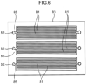
- one relay flow path 85 is connected to a peripheral surface of the introduction path 82, and a large number of the first flow paths 81 are connected to the relay flow path 85 so as to be branched from the relay flow path 85.
- an introduction path is provided so as to penetrate the first heat exchanger plate and the second heat exchanger plate.
- a plurality of relay flow paths 85 are connected to a peripheral surface of an introduction path 82, and a large number of first flow paths 81 are connected to the relay flow paths 85 so as to be branched from the plurality of relay flow paths 85.
- An object of the present invention is to reduce local and intensive generation of thermal stress in a layer having a plurality of flow paths through which a cooling medium or hydrogen gas flows in a microchannel heat exchanger.
- a microchannel heat exchanger is a microchannel heat exchanger for cooling hydrogen gas with a cooling medium.
- the microchannel heat exchanger includes a cooling side layer formed with a plurality of medium flow paths for flowing the cooling medium, and a high temperature side layer placed on the cooling side layer, the high temperature side layer being formed with a plurality of hydrogen flow paths for flowing the hydrogen gas and an introduction port for flowing the hydrogen gas into the plurality of hydrogen flow paths.
- the introduction port has a circular shape or an elliptical shape. An inflow end of each of the plurality of hydrogen flow paths is connected to a peripheral surface of the introduction port.
- the cooling side layer and the high temperature side layer include a heat exchange region in which the plurality of medium flow paths and the plurality of hydrogen flow paths overlap each other in a direction in which the cooling side layer and the high temperature side layer are placed on each other.
- the plurality of hydrogen flow paths extend from the inflow end to the heat exchange region without branching.
- a microchannel heat exchanger is to be used as a pre-cooler of a hydrogen station and is configured as a heat exchanger that cools hydrogen gas with a cooling medium. That is, since a tank of a fuel cell vehicle or the like is filled with hydrogen gas supplied from a hydrogen station at a high pressure (pressure of 10 MPa or more), a temperature of the hydrogen gas rises in the tank. For this reason, the hydrogen gas is cooled by a cooling medium in the pre-cooler before being supplied to the tank. Note that, as the cooling medium, brine, carbon dioxide, alternative CFCs, or the like can be used.
- the microchannel heat exchanger is not limited to one used as a pre-cooler of a hydrogen station as long as the microchannel heat exchanger is used as a heat exchanger for cooling hydrogen gas.
- a microchannel heat exchanger 10 includes a plurality of high temperature side layers 12 and a plurality of cooling side layers 14.
- the plurality of high temperature side layers 12 and the plurality of cooling side layers 14 are arranged in a stack in a thickness direction in a manner that the high temperature side layer 12 and the cooling side layer 14 are alternately arranged.
- Fig. 1 illustrates an example in which the plurality of high temperature side layers 12 and the plurality of cooling side layers 14 are laminated, but the present invention is not limited to this.
- a microchannel heat exchanger 10 may include one high temperature side layer 12 and one cooling side layer 14 arranged in stack.
- the high temperature side layer 12 and the cooling side layer 14 are respectively formed of metal plates 12a and 14a made from a material having high thermal conductivity.
- a plurality of the metal plates 12a and 14a placed on each other are, for example, diffusion bonded to each other to form a laminate (stack) 18 having a plurality of the high temperature side layers 12 and a plurality of the cooling side layers 14.
- Long and thin grooves are formed on one surface of each of the metal plates 12a and 14a. For this reason, as a plurality of the metal plates 12a and 14a are laminated, flow paths 33 and 34 including a microchannel are formed in the high temperature side layer 12 and the cooling side layer 14, respectively.
- End plates 19a and 19b are provided on both sides of the laminate 18 in a superposing direction (vertical direction in Fig. 1 ).
- the laminate 18 is not limited to a structure in which the high temperature side layer 12 and the cooling side layer 14 are bonded by diffusion bonding. In a case where the metal plates 12a and 14a are diffusion bonded to each other, a boundary between the high temperature side layer 12 and the cooling side layer 14 does not clearly appear, but in a case where another bonding method is used, a boundary between the layers 12 and 14 may appear.
- the laminate 18 is provided with a first introduction header 21, a first lead out header 22, a second introduction header 23, and a second lead out header 24.
- the first introduction header 21 allows hydrogen gas from the outside of the laminate 18 to flow into the hydrogen flow path 33 described later.
- the first lead out header 22 allows hydrogen gas flowing through the hydrogen flow path 33 to flow out to the outside.
- the second introduction header 23 introduces a cooling medium from the outside of the laminate 18 into the medium flow path 34 described later.
- the second lead out header 24 leads out to the outside a cooling medium flowing through the medium flow path 34.
- Fig. 1 illustrates a configuration in which the first introduction header 21 and the first lead out header 22 are provided on one surface of the laminate 18. Alternatively, the first introduction header 21 and the first lead out header 22 may be provided on opposite surfaces of the laminate 18. The above similarly applies to the second introduction header 23 and the second lead out header 24.
- a first introduction path 27 is connected to the first introduction header 21.
- the first introduction path 27 is a flow path for allowing hydrogen gas to flow from the outside of the laminate 18 (or the first introduction header 21) to each of the hydrogen flow paths 33 described later, and is formed so as to penetrate the high temperature side layers 12 and the cooling side layers 14. Note that an end portion of the first introduction path 27 on the opposite side to the first introduction header 21 is closed.
- a first lead out path 28 is connected to the first lead out header 22.
- the first lead out path 28 is a flow path for leading out hydrogen gas flowing through each of the hydrogen flow paths 33 described later to the outside of laminate 18 (or the first lead out header 22), and is formed so as to penetrate the high temperature side layers 12 and the cooling side layers 14. Note that an end portion of the first lead out path 28 on the opposite side to the first lead out header 22 is closed.
- a second introduction path 29 (see Fig. 4 ) is connected to the second introduction header 23.
- the second introduction path 29 is a flow path for allowing a cooling medium to flow from the outside of the laminate 18 (or the second introduction header 23) to each of the medium flow paths 34 described later, and is formed so as to penetrate the high temperature side layers 12 and the cooling side layers 14. Note that an end portion of the second introduction path 29 on the opposite side to the second introduction header 23 is closed.
- a second lead out path 30 (see Fig. 4 ) is connected to the second lead out header 24.
- the second lead out path 30 is a flow path for leading out a cooling medium flowing through each of the medium flow paths 34 described later to the outside of the laminate 18 (or the second lead out header 24), and is formed so as to penetrate the high temperature side layers 12 and the cooling side layers 14. Note that an end portion of the second lead out path 30 on the opposite side to the second lead out header 24 is closed.
- each of the high temperature side layers 12 is formed as a flat region including a plurality of the hydrogen flow paths 33
- each of the cooling side layers 14 is formed as a flat region including a plurality of the medium flow paths 34.
- a plurality of the hydrogen flow paths 33 are arranged so as to be aligned in one direction (lateral direction in Fig. 2 ) in the high temperature side layer 12, and a plurality of the medium flow paths 34 are arranged in the cooling side layer 14 so as to be aligned in the same direction as the direction in which the hydrogen flow paths 33 are arranged.
- a plurality of the hydrogen flow paths 33 are aligned in one direction and a plurality of the medium flow paths 34 are aligned in one direction.
- a plurality of the hydrogen flow paths 33 and a plurality of the medium flow paths 34 are alternately arranged in a superposing direction (vertical direction in Fig. 2 ). That is, in a cross section of the laminate 18 illustrated in Fig. 2 , a plurality of the hydrogen flow paths 33 and a plurality of the medium flow paths 34 extend in the same direction.
- a plurality of the hydrogen flow paths 33 and a plurality of the medium flow paths 34 are not necessarily formed so as to extend in the same direction at any place of the laminate 18.
- a plurality of the hydrogen flow paths 33 and a plurality of the medium flow paths 34 may extend in the same direction at one place in the laminate 18, and a plurality of the hydrogen flow paths 33 and a plurality of the medium flow paths 34 may extend in different directions at another place in the laminate 18.
- all of the hydrogen flow paths 33 and the medium flow paths 34 have a semicircular cross section.
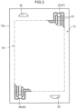
- the metal plate 12a forming the high temperature side layer 12 is formed in a rectangular shape in top view, and a plurality of the hydrogen flow paths 33 are formed on an upper surface of the metal plate 12a.
- a first introduction port 37 and a first lead out port 38 are formed so as to penetrate the metal plate 12a in a thickness direction.
- the first introduction port 37 is a part of the first introduction path 27 penetrating the high temperature side layers 12 and the cooling side layers 14, the first introduction port 37 being a part of the first introduction path 27 located in the high temperature side layer 12 formed of the metal plate 12a.
- the first lead out port 38 is a part of the first lead out path 28 penetrating the high temperature side layers 12 and the cooling side layers 14, the first lead out port 38 being a part of the first lead out path 28 in the high temperature side layer 12 formed of the metal plate 12a.
- the first introduction port 37 and the first lead out port 38 have circular or elliptical shape.
- One end (inflow end) of each of the hydrogen flow paths 33 is connected to a peripheral surface of the first introduction port 37.
- inflow ends of the hydrogen flow paths 33 in one of the high temperature side layers 12 are connected to a peripheral surface of the first introduction port 37 at intervals in a circumferential direction of the first introduction port 37, and these connection portions are located over the entire circumference of the first introduction port 37.
- “over the entire circumference” means that a plurality of connection portions exist at intervals over the entire circumference of the first introduction port 37. For this reason, a portion to which the hydrogen flow path 33 is not connected may exist on a part of the circumference of the first introduction port 37.
- connection portions do not need to be at equal intervals. That is, an interval between adjacent connection portions may be wider than an interval between other adjacent connection portions. It is sufficient that a width of an interval between any adjacent connection portions is 1/4 (or 1/6 or 1/8) or less of a circumference of the first introduction port 37.
- a relationship between connection portions of a plurality of the hydrogen flow paths 33 to the first introduction port 37 is the same in any of the high temperature side layers 12.
- each of the hydrogen flow paths 33 is connected to a peripheral surface of the first lead out port 38. Then, each of the hydrogen flow paths 33 extends from the first introduction port 37 to the first lead out port 38 without branching. Hydrogen gas in the first introduction path 27 is distributed to each of the hydrogen flow paths 33 in each of the high temperature side layers 12. Hydrogen gas flowing through each of the hydrogen flow paths 33 joins the first lead out path 28 (first lead out port 38) without being divided, and is sent to the outside of the microchannel heat exchanger 10 through the first lead out header 22.
- connection portions of the hydrogen flow path 33 to the first lead out port 38 may be located at intervals over the entire circumference of the first lead out port 38, but is not necessarily required to be located over the entire circumference, and the connection portions may exist, for example, within a range of 2/3 of the circumference.
- the metal plate 14a forming the cooling side layer 14 is formed in a rectangular shape in top view, and a plurality of the medium flow paths 34 are formed on an upper surface of the metal plate 14a.
- the number of the medium flow paths 34 is larger than the number of the hydrogen flow paths 33. For this reason, when a cooling medium flowing through the medium flow path 34 exchanges heat with hydrogen gas, a temperature of the cooling medium does not change much as compared with a temperature change of hydrogen gas.
- hydrogen gas flowing through the hydrogen flow path 33 greatly changes in temperature upon heat exchange with a cooling medium, and the temperature approaches a temperature of the cooling medium. That is, a temperature change amount of hydrogen gas in the hydrogen flow path 33 is larger than a temperature change amount of a cooling medium in the medium flow path 34.
- a second introduction port (medium introduction port) 39 and a second lead out port (medium lead out port) 40 are formed in the metal plate 14a so as to penetrate the metal plate 14a in a thickness direction.
- the second introduction port 39 is a portion of the cooling side layer 14 formed of the metal plate 14a in the second introduction path 29 penetrating the high temperature side layers 12 and the cooling side layers 14.
- the second lead out port 40 is a portion of the cooling side layer 14 formed of the metal plate 14a in the second lead out path 30 penetrating the high temperature side layers 12 and the cooling side layers 14.
- the second introduction port 39 and the second lead out port 40 have a semicircular shape having an area larger than those of the first introduction port 37 and the first lead out port 38. That is, a flow rate of a cooling medium introduced through the second introduction path 29 is larger than a flow rate of hydrogen gas introduced through the first introduction path 27.
- a shape of the second introduction port 39 and the second lead out port 40 is not limited to a semicircular shape as long as a flow rate of a cooling medium can be secured, and may be, for example, a circular shape or an elliptical shape.
- each of the medium flow paths 34 One end (introduction end) of each of the medium flow paths 34 is connected to a portion corresponding to a chord of a semicircle of a circumference of the second introduction port 39.
- the other end (lead out end) of each of the medium flow paths 34 is connected to a portion corresponding to a chord of a semicircle of a circumference of the second lead out port 40.
- each of the medium flow paths 34 extends from the second introduction port 39 to the second lead out port 40.
- a cooling medium in the second introduction path 29 is divided into the medium flow paths 34 in each of the cooling side layers 14.
- a cooling medium flowing through each of the medium flow paths 34 joins the second lead out path 30 (second lead out port 40) without being divided, and is sent to the outside of the microchannel heat exchanger 10 through the second lead out header 24.
- a region overlapping the medium flow path 34 in a direction in which the high temperature side layer 12 and the cooling side layer 14 are arranged in a stack is a heat exchange region 43. That is, if hydrogen gas flows into the hydrogen flow path 33 from the first introduction port 37, the hydrogen gas hardly exchanges heat with a cooling medium until reaching the heat exchange region 43. Then, hydrogen gas exchanges heat with a cooling medium flowing through the medium flow path 34 while flowing through the hydrogen flow path 33 in the heat exchange region 43.
- each of the hydrogen flow paths 33 which extends from the first introduction port 37 to the first lead out port 38 without branching, does not branch at least from the first introduction port 37 to the heat exchange region 43, and does not branch also in a first half portion having a relatively large temperature difference from a cooling medium also in the heat exchange region 43. Note that, in a second half of the heat exchange region 43 and after that, each of the hydrogen flow paths 33 may branch.
- Hydrogen gas flows into the hydrogen flow path 33 at a temperature of, for example, 30°C or more, and a cooling medium flows into the medium flow path 34 at a temperature of - 30°C or less.
- Hydrogen gas may circulate through the hydrogen flow path 33 in a very high pressure (pressure of 10 MPa or more) state. Then, when passing through the heat exchange region 43, hydrogen gas is cooled to a temperature of -30°C or less. That is, a temperature of hydrogen gas changes from a positive temperature zone to a negative temperature zone while hydrogen gas flowing through the hydrogen flow path 33.
- a cooling medium has a temperature of -30°C or less even when passing through the heat exchange region 43. That is, a cooling medium flows through the medium flow path 34 in a negative temperature zone. Therefore, a temperature change of hydrogen gas from the first introduction port 37 to the first lead out port 38 is larger than a temperature change of a cooling medium from the second introduction port 39 to the second lead out port 40.
- the microchannel heat exchanger 10 is for a hydrogen station, and the inside of the heat exchanger 10 is exposed to a high pressure because extremely high pressure hydrogen gas is circulated. For this reason, stress generated in the microchannel heat exchanger 10 further increases.
- the first introduction port 37 for allowing hydrogen gas to flow in has a circular or elliptical cross section, stress such as the thermal stress is suppressed to be locally concentrated in a portion where a plurality of the hydrogen flow paths 33 are connected to a peripheral surface of the first introduction port 37.
- the first introduction port 37 has semicircular shape
- stress may be locally generated at a corner portion of a semicircle.
- the first introduction port 37 has circular or elliptical shape
- stress concentration hardly occurs in the vicinity of a peripheral surface.
- the hydrogen flow path 33 is not branched in a range in which hydrogen gas before being cooled by a cooling medium flows, it is also possible to suppressed to occur local concentration of thermal stress caused by the temperature difference and stress caused by internal pressure in the vicinity of the hydrogen flow path 33.
- inflow ends of the hydrogen flow paths 33 are located at intervals over the entire circumference of the first introduction port 37, a large number of the hydrogen flow paths 33 can be connected to the first introduction port 37. That is, when the number of the hydrogen flow paths 33 is increased, a flow rate of hydrogen gas can be increased, and accordingly, thermal stress caused by a temperature difference between a cooling medium and hydrogen gas is likely to be generated. However, since local generation of thermal stress is suppressed as described above, it is possible to increase a flow rate of hydrogen gas while suppressing an adverse effect due to stress concentration.
- the hydrogen flow path 33 is configured not to branch from the first introduction port 37 to the first lead out port 38, it is possible to prevent local generation of stress over the entire hydrogen flow path 33. Therefore, in a case where the microchannel heat exchanger 10 is used for a purpose where thermal stress or stress caused by internal pressure is likely to occur, it is possible to reduce influence on durability of the high temperature side layer 12 or the cooling side layer 14.
- the microchannel heat exchanger 10 is used as a pre-cooler of a hydrogen station.
- a hydrogen station supply and stop of hydrogen gas are repeated depending on presence or absence of a fuel cell vehicle or the like to be charged with hydrogen gas.
- a pre-cooler hydrogen gas is repeatedly cooled and stopped.
- hydrogen gas having an extremely high pressure pressure of 10 MPa or more
- the microchannel heat exchanger 10 used as a pre-cooler is configured to suppress stress to be locally concentrated, it is possible to reduce influence on deterioration of durability of the microchannel heat exchanger 10.
- the embodiment disclosed herein is illustrative in all respects and is not restrictive.
- the present invention is not limited to the above embodiment, and various modifications, improvements, and the like can be made without departing from the gist of the present invention.
- the second introduction port 39 and the second lead out port 40 are formed as a part of the second introduction path 29 or the second lead out path 30 penetrating the high temperature side layers 12 and the cooling side layers 14, but the present embodiment is not limited to this.
- the second introduction port 39 and the second lead out port 40 may be opened to an outer peripheral surface (side surface) of the metal plates 12a or 14a forming the high temperature side layer 12 or the cooling side layer 14, instead of penetrating the metal plate 14a in a thickness direction. That is, one end (introduction end) of the medium flow path 34 may be opened to an outer peripheral surface (side surface) of the metal plate 14a as the second introduction port 39. The other end (leading end) of the medium flow path 34 may be opened to an outer peripheral surface (side surface) of the metal plate 14a as the second lead out port 40.
- the second introduction header 23 is provided on a side surface of the laminate 18 where the second introduction port 39 is opened, and the second lead out header 24 is provided on a side surface of the laminate 18 where the second lead out port 40 is opened.
- the second introduction path 29 and the second lead out path 30 are omitted.
- microchannel heat exchanger 10 may be directly connected to a device or the like at a preceding stage or a subsequent stage without a pipe or the like.
- introduction headers 21 and 23 and the lead out headers 22 and 24 are omitted.
- the microchannel heat exchanger it is possible to prevent local and intensive generation of thermal stress in a layer having a plurality of flow paths through which a cooling medium or hydrogen gas flows.
- a microchannel heat exchanger is a heat exchanger for cooling hydrogen gas with a cooling medium, and includes a cooling side layer formed with a plurality of medium flow paths for flowing the cooling medium, and a high temperature side layer formed with a plurality of hydrogen flow paths for flowing the hydrogen gas and a first introduction port for flowing the hydrogen gas into the plurality of hydrogen flow paths.
- the first introduction port has a circular shape or an elliptical shape. An inflow end of each of the plurality of hydrogen flow paths is connected to a peripheral surface of the first introduction port.
- the hydrogen flow path extends from the first introduction port to the first lead out port without branching.
Landscapes
- Engineering & Computer Science (AREA)
- Physics & Mathematics (AREA)
- Thermal Sciences (AREA)
- Mechanical Engineering (AREA)
- General Engineering & Computer Science (AREA)
- Heat-Exchange Devices With Radiators And Conduit Assemblies (AREA)
- Fuel Cell (AREA)
Abstract
Description
- The present invention relates to a microchannel heat exchanger.
- In recent years, in consideration of the environment, use of hydrogen for power generation and as fuel for an automobile, and the like is considered, and demand for hydrogen is increasing. Further, a hydrogen station for filling a tank of an automobile or the like with hydrogen gas is also known. On the other hand, as disclosed in
JP 2017-180984 A JP 5847913 B1 - In the microchannel heat exchanger disclosed in
JP 2017-180984 A Fig. 5 , anintroduction path 82 for introducing one fluid into afirst flow path 81 is provided so as to penetrate a firstheat exchanger plate 83 and a secondheat exchanger plate 84. Then, as illustrated inFig. 6 , onerelay flow path 85 is connected to a peripheral surface of theintroduction path 82, and a large number of thefirst flow paths 81 are connected to therelay flow path 85 so as to be branched from therelay flow path 85. - Similarly, in the microchannel heat exchanger disclosed in
JP 5847913 B1 JP 5847913 B1 Fig. 7 , a plurality ofrelay flow paths 85 are connected to a peripheral surface of anintroduction path 82, and a large number offirst flow paths 81 are connected to therelay flow paths 85 so as to be branched from the plurality ofrelay flow paths 85. - In the microchannel heat exchangers disclosed in
JP 2017-180984 A JP 5847913 B1 introduction path 82 is circular, if one or the plurality ofrelay flow paths 85 are connected to a peripheral surface of theintroduction path 82, generation of local thermal stress is reduced at the connection portion. That is, since theintroduction path 82 has a circular cross section and no corner portion having a section shape or the like is formed on a peripheral surface of theintroduction path 82, stress concentration hardly occurs in theintroduction path 82. However, only theintroduction path 82 having a circular cross section is insufficient for reducing stress concentration. - An object of the present invention is to reduce local and intensive generation of thermal stress in a layer having a plurality of flow paths through which a cooling medium or hydrogen gas flows in a microchannel heat exchanger.
- A microchannel heat exchanger according to one aspect of the present invention is a microchannel heat exchanger for cooling hydrogen gas with a cooling medium. The microchannel heat exchanger includes a cooling side layer formed with a plurality of medium flow paths for flowing the cooling medium, and a high temperature side layer placed on the cooling side layer, the high temperature side layer being formed with a plurality of hydrogen flow paths for flowing the hydrogen gas and an introduction port for flowing the hydrogen gas into the plurality of hydrogen flow paths. The introduction port has a circular shape or an elliptical shape. An inflow end of each of the plurality of hydrogen flow paths is connected to a peripheral surface of the introduction port. The cooling side layer and the high temperature side layer include a heat exchange region in which the plurality of medium flow paths and the plurality of hydrogen flow paths overlap each other in a direction in which the cooling side layer and the high temperature side layer are placed on each other. The plurality of hydrogen flow paths extend from the inflow end to the heat exchange region without branching.
-
-
Fig. 1 is a side view of a microchannel heat exchanger according to an embodiment. -
Fig. 2 is a partial cross-sectional view of a laminate in the microchannel heat exchanger. -
Fig. 3 is a top view of a metal plate constituting a high temperature side layer of the microchannel heat exchanger. -
Fig. 4 is a top view of a metal plate constituting a cooling side layer of the microchannel heat exchanger. -
Fig. 5 is a side view of a conventional microchannel heat exchanger. -
Fig. 6 is a top view of a first heat exchanger plate constituting a conventional microchannel heat exchanger. -
Fig. 7 is a top view of a first heat exchanger plate constituting a conventional microchannel heat exchanger. - An embodiment of the present invention will hereinafter be described in detail with reference to the drawings.
- A microchannel heat exchanger according to the present embodiment is to be used as a pre-cooler of a hydrogen station and is configured as a heat exchanger that cools hydrogen gas with a cooling medium. That is, since a tank of a fuel cell vehicle or the like is filled with hydrogen gas supplied from a hydrogen station at a high pressure (pressure of 10 MPa or more), a temperature of the hydrogen gas rises in the tank. For this reason, the hydrogen gas is cooled by a cooling medium in the pre-cooler before being supplied to the tank. Note that, as the cooling medium, brine, carbon dioxide, alternative CFCs, or the like can be used. However, the microchannel heat exchanger is not limited to one used as a pre-cooler of a hydrogen station as long as the microchannel heat exchanger is used as a heat exchanger for cooling hydrogen gas.
- As illustrated in
Fig. 1 , amicrochannel heat exchanger 10 includes a plurality of hightemperature side layers 12 and a plurality ofcooling side layers 14. The plurality of hightemperature side layers 12 and the plurality ofcooling side layers 14 are arranged in a stack in a thickness direction in a manner that the hightemperature side layer 12 and thecooling side layer 14 are alternately arranged.Fig. 1 illustrates an example in which the plurality of hightemperature side layers 12 and the plurality ofcooling side layers 14 are laminated, but the present invention is not limited to this. For example, amicrochannel heat exchanger 10 may include one hightemperature side layer 12 and onecooling side layer 14 arranged in stack. - The high
temperature side layer 12 and thecooling side layer 14 are respectively formed ofmetal plates metal plates temperature side layers 12 and a plurality of thecooling side layers 14. Long and thin grooves are formed on one surface of each of themetal plates metal plates flow paths temperature side layer 12 and thecooling side layer 14, respectively.End plates laminate 18 in a superposing direction (vertical direction inFig. 1 ). - Note that the
laminate 18 is not limited to a structure in which the hightemperature side layer 12 and thecooling side layer 14 are bonded by diffusion bonding. In a case where themetal plates temperature side layer 12 and thecooling side layer 14 does not clearly appear, but in a case where another bonding method is used, a boundary between thelayers - The
laminate 18 is provided with afirst introduction header 21, a first lead outheader 22, asecond introduction header 23, and a second lead outheader 24. Thefirst introduction header 21 allows hydrogen gas from the outside of thelaminate 18 to flow into thehydrogen flow path 33 described later. The first lead outheader 22 allows hydrogen gas flowing through thehydrogen flow path 33 to flow out to the outside. Thesecond introduction header 23 introduces a cooling medium from the outside of thelaminate 18 into themedium flow path 34 described later. The second lead outheader 24 leads out to the outside a cooling medium flowing through themedium flow path 34.Fig. 1 illustrates a configuration in which thefirst introduction header 21 and the first lead outheader 22 are provided on one surface of thelaminate 18. Alternatively, thefirst introduction header 21 and the first lead outheader 22 may be provided on opposite surfaces of thelaminate 18. The above similarly applies to thesecond introduction header 23 and the second lead outheader 24. - A
first introduction path 27 is connected to thefirst introduction header 21. Thefirst introduction path 27 is a flow path for allowing hydrogen gas to flow from the outside of the laminate 18 (or the first introduction header 21) to each of thehydrogen flow paths 33 described later, and is formed so as to penetrate the hightemperature side layers 12 and thecooling side layers 14. Note that an end portion of thefirst introduction path 27 on the opposite side to thefirst introduction header 21 is closed. - A first lead out
path 28 is connected to the first lead outheader 22. The first lead outpath 28 is a flow path for leading out hydrogen gas flowing through each of thehydrogen flow paths 33 described later to the outside of laminate 18 (or the first lead out header 22), and is formed so as to penetrate the hightemperature side layers 12 and thecooling side layers 14. Note that an end portion of the first lead outpath 28 on the opposite side to the first lead outheader 22 is closed. - A second introduction path 29 (see
Fig. 4 ) is connected to thesecond introduction header 23. Thesecond introduction path 29 is a flow path for allowing a cooling medium to flow from the outside of the laminate 18 (or the second introduction header 23) to each of themedium flow paths 34 described later, and is formed so as to penetrate the hightemperature side layers 12 and thecooling side layers 14. Note that an end portion of thesecond introduction path 29 on the opposite side to thesecond introduction header 23 is closed. - A second lead out path 30 (see
Fig. 4 ) is connected to the second lead outheader 24. The second lead outpath 30 is a flow path for leading out a cooling medium flowing through each of themedium flow paths 34 described later to the outside of the laminate 18 (or the second lead out header 24), and is formed so as to penetrate the high temperature side layers 12 and the cooling side layers 14. Note that an end portion of the second lead outpath 30 on the opposite side to the second lead outheader 24 is closed. - As illustrated in
Fig. 2 , each of the high temperature side layers 12 is formed as a flat region including a plurality of thehydrogen flow paths 33, and each of the cooling side layers 14 is formed as a flat region including a plurality of themedium flow paths 34. A plurality of thehydrogen flow paths 33 are arranged so as to be aligned in one direction (lateral direction inFig. 2 ) in the hightemperature side layer 12, and a plurality of themedium flow paths 34 are arranged in thecooling side layer 14 so as to be aligned in the same direction as the direction in which thehydrogen flow paths 33 are arranged. That is, since themetal plates metal plates hydrogen flow paths 33 are aligned in one direction and a plurality of themedium flow paths 34 are aligned in one direction. A plurality of thehydrogen flow paths 33 and a plurality of themedium flow paths 34 are alternately arranged in a superposing direction (vertical direction inFig. 2 ). That is, in a cross section of the laminate 18 illustrated inFig. 2 , a plurality of thehydrogen flow paths 33 and a plurality of themedium flow paths 34 extend in the same direction. However, a plurality of thehydrogen flow paths 33 and a plurality of themedium flow paths 34 are not necessarily formed so as to extend in the same direction at any place of the laminate 18. For example, a plurality of thehydrogen flow paths 33 and a plurality of themedium flow paths 34 may extend in the same direction at one place in the laminate 18, and a plurality of thehydrogen flow paths 33 and a plurality of themedium flow paths 34 may extend in different directions at another place in thelaminate 18. Note that all of thehydrogen flow paths 33 and themedium flow paths 34 have a semicircular cross section. - As illustrated in
Fig. 3 , themetal plate 12a forming the hightemperature side layer 12 is formed in a rectangular shape in top view, and a plurality of thehydrogen flow paths 33 are formed on an upper surface of themetal plate 12a. - In the
metal plate 12a, afirst introduction port 37 and a first lead outport 38 are formed so as to penetrate themetal plate 12a in a thickness direction. Thefirst introduction port 37 is a part of thefirst introduction path 27 penetrating the high temperature side layers 12 and the cooling side layers 14, thefirst introduction port 37 being a part of thefirst introduction path 27 located in the hightemperature side layer 12 formed of themetal plate 12a. The first lead outport 38 is a part of the first lead outpath 28 penetrating the high temperature side layers 12 and the cooling side layers 14, the first lead outport 38 being a part of the first lead outpath 28 in the hightemperature side layer 12 formed of themetal plate 12a. - The
first introduction port 37 and the first lead outport 38 have circular or elliptical shape. One end (inflow end) of each of thehydrogen flow paths 33 is connected to a peripheral surface of thefirst introduction port 37. Specifically, inflow ends of thehydrogen flow paths 33 in one of the high temperature side layers 12 are connected to a peripheral surface of thefirst introduction port 37 at intervals in a circumferential direction of thefirst introduction port 37, and these connection portions are located over the entire circumference of thefirst introduction port 37. Here, "over the entire circumference" means that a plurality of connection portions exist at intervals over the entire circumference of thefirst introduction port 37. For this reason, a portion to which thehydrogen flow path 33 is not connected may exist on a part of the circumference of thefirst introduction port 37. Further, a plurality of connection portions do not need to be at equal intervals. That is, an interval between adjacent connection portions may be wider than an interval between other adjacent connection portions. It is sufficient that a width of an interval between any adjacent connection portions is 1/4 (or 1/6 or 1/8) or less of a circumference of thefirst introduction port 37. A relationship between connection portions of a plurality of thehydrogen flow paths 33 to thefirst introduction port 37 is the same in any of the high temperature side layers 12. - The other end (outflow end) of each of the
hydrogen flow paths 33 is connected to a peripheral surface of the first lead outport 38. Then, each of thehydrogen flow paths 33 extends from thefirst introduction port 37 to the first lead outport 38 without branching. Hydrogen gas in thefirst introduction path 27 is distributed to each of thehydrogen flow paths 33 in each of the high temperature side layers 12. Hydrogen gas flowing through each of thehydrogen flow paths 33 joins the first lead out path 28 (first lead out port 38) without being divided, and is sent to the outside of themicrochannel heat exchanger 10 through the first lead outheader 22. - Note that, since a temperature of hydrogen gas is close to a temperature of a cooling medium at an outflow end of the
hydrogen flow path 33, the first lead outport 38 does not need to be circular or elliptical, and may be semicircular, for example. Further, connection portions of thehydrogen flow path 33 to the first lead outport 38 may be located at intervals over the entire circumference of the first lead outport 38, but is not necessarily required to be located over the entire circumference, and the connection portions may exist, for example, within a range of 2/3 of the circumference. - As illustrated in
Fig. 4 , themetal plate 14a forming thecooling side layer 14 is formed in a rectangular shape in top view, and a plurality of themedium flow paths 34 are formed on an upper surface of themetal plate 14a. The number of themedium flow paths 34 is larger than the number of thehydrogen flow paths 33. For this reason, when a cooling medium flowing through themedium flow path 34 exchanges heat with hydrogen gas, a temperature of the cooling medium does not change much as compared with a temperature change of hydrogen gas. On the other hand, hydrogen gas flowing through thehydrogen flow path 33 greatly changes in temperature upon heat exchange with a cooling medium, and the temperature approaches a temperature of the cooling medium. That is, a temperature change amount of hydrogen gas in thehydrogen flow path 33 is larger than a temperature change amount of a cooling medium in themedium flow path 34. - A second introduction port (medium introduction port) 39 and a second lead out port (medium lead out port) 40 are formed in the
metal plate 14a so as to penetrate themetal plate 14a in a thickness direction. Thesecond introduction port 39 is a portion of thecooling side layer 14 formed of themetal plate 14a in thesecond introduction path 29 penetrating the high temperature side layers 12 and the cooling side layers 14. The second lead outport 40 is a portion of thecooling side layer 14 formed of themetal plate 14a in the second lead outpath 30 penetrating the high temperature side layers 12 and the cooling side layers 14. - The
second introduction port 39 and the second lead outport 40 have a semicircular shape having an area larger than those of thefirst introduction port 37 and the first lead outport 38. That is, a flow rate of a cooling medium introduced through thesecond introduction path 29 is larger than a flow rate of hydrogen gas introduced through thefirst introduction path 27. Note that a shape of thesecond introduction port 39 and the second lead outport 40 is not limited to a semicircular shape as long as a flow rate of a cooling medium can be secured, and may be, for example, a circular shape or an elliptical shape. - One end (introduction end) of each of the
medium flow paths 34 is connected to a portion corresponding to a chord of a semicircle of a circumference of thesecond introduction port 39. The other end (lead out end) of each of themedium flow paths 34 is connected to a portion corresponding to a chord of a semicircle of a circumference of the second lead outport 40. Then, each of themedium flow paths 34 extends from thesecond introduction port 39 to the second lead outport 40. A cooling medium in thesecond introduction path 29 is divided into themedium flow paths 34 in each of the cooling side layers 14. A cooling medium flowing through each of themedium flow paths 34 joins the second lead out path 30 (second lead out port 40) without being divided, and is sent to the outside of themicrochannel heat exchanger 10 through the second lead outheader 24. - In the
hydrogen flow path 33, a region overlapping themedium flow path 34 in a direction in which the hightemperature side layer 12 and thecooling side layer 14 are arranged in a stack (superposing direction or vertical direction inFig. 2 ) is aheat exchange region 43. That is, if hydrogen gas flows into thehydrogen flow path 33 from thefirst introduction port 37, the hydrogen gas hardly exchanges heat with a cooling medium until reaching theheat exchange region 43. Then, hydrogen gas exchanges heat with a cooling medium flowing through themedium flow path 34 while flowing through thehydrogen flow path 33 in theheat exchange region 43. - In the present embodiment, each of the
hydrogen flow paths 33, which extends from thefirst introduction port 37 to the first lead outport 38 without branching, does not branch at least from thefirst introduction port 37 to theheat exchange region 43, and does not branch also in a first half portion having a relatively large temperature difference from a cooling medium also in theheat exchange region 43. Note that, in a second half of theheat exchange region 43 and after that, each of thehydrogen flow paths 33 may branch. - Hydrogen gas flows into the
hydrogen flow path 33 at a temperature of, for example, 30°C or more, and a cooling medium flows into themedium flow path 34 at a temperature of - 30°C or less. Hydrogen gas may circulate through thehydrogen flow path 33 in a very high pressure (pressure of 10 MPa or more) state. Then, when passing through theheat exchange region 43, hydrogen gas is cooled to a temperature of -30°C or less. That is, a temperature of hydrogen gas changes from a positive temperature zone to a negative temperature zone while hydrogen gas flowing through thehydrogen flow path 33. On the other hand, a cooling medium has a temperature of -30°C or less even when passing through theheat exchange region 43. That is, a cooling medium flows through themedium flow path 34 in a negative temperature zone. Therefore, a temperature change of hydrogen gas from thefirst introduction port 37 to the first lead outport 38 is larger than a temperature change of a cooling medium from thesecond introduction port 39 to the second lead outport 40. - As described above, in the present embodiment, when hydrogen gas is cooled by a cooling medium, thermal stress is generated in the high
temperature side layer 12 or thecooling side layer 14 due to a temperature difference between the cooling medium and the hydrogen gas. Further, in the present embodiment, themicrochannel heat exchanger 10 is for a hydrogen station, and the inside of theheat exchanger 10 is exposed to a high pressure because extremely high pressure hydrogen gas is circulated. For this reason, stress generated in themicrochannel heat exchanger 10 further increases. However, since thefirst introduction port 37 for allowing hydrogen gas to flow in has a circular or elliptical cross section, stress such as the thermal stress is suppressed to be locally concentrated in a portion where a plurality of thehydrogen flow paths 33 are connected to a peripheral surface of thefirst introduction port 37. That is, in a case where thefirst introduction port 37 has semicircular shape, stress may be locally generated at a corner portion of a semicircle. However, since thefirst introduction port 37 has circular or elliptical shape, stress concentration hardly occurs in the vicinity of a peripheral surface. Further, since thehydrogen flow path 33 is not branched in a range in which hydrogen gas before being cooled by a cooling medium flows, it is also possible to suppressed to occur local concentration of thermal stress caused by the temperature difference and stress caused by internal pressure in the vicinity of thehydrogen flow path 33. That is, in a portion where hydrogen gas before being cooled by a cooling medium flows in thehydrogen flow path 33, not only stress caused by internal pressure of high pressure is generated, but also thermal stress caused by a large temperature difference between a cooling medium and hydrogen gas is likely to become high. For this reason, if a branch is provided at this portion, stress tends to concentrate at the branch portion. However, in this portion, since a branch point of thehydrogen flow path 33 is not provided, stress is prevented from being locally concentrated. Further, this contributes to stable supply of hydrogen gas. - Further, in the present embodiment, since inflow ends of the
hydrogen flow paths 33 are located at intervals over the entire circumference of thefirst introduction port 37, a large number of thehydrogen flow paths 33 can be connected to thefirst introduction port 37. That is, when the number of thehydrogen flow paths 33 is increased, a flow rate of hydrogen gas can be increased, and accordingly, thermal stress caused by a temperature difference between a cooling medium and hydrogen gas is likely to be generated. However, since local generation of thermal stress is suppressed as described above, it is possible to increase a flow rate of hydrogen gas while suppressing an adverse effect due to stress concentration. - Further, in the present embodiment, since the
hydrogen flow path 33 is configured not to branch from thefirst introduction port 37 to the first lead outport 38, it is possible to prevent local generation of stress over the entirehydrogen flow path 33. Therefore, in a case where themicrochannel heat exchanger 10 is used for a purpose where thermal stress or stress caused by internal pressure is likely to occur, it is possible to reduce influence on durability of the hightemperature side layer 12 or thecooling side layer 14. - Further, the
microchannel heat exchanger 10 according to the present embodiment is used as a pre-cooler of a hydrogen station. In a hydrogen station, supply and stop of hydrogen gas are repeated depending on presence or absence of a fuel cell vehicle or the like to be charged with hydrogen gas. For this reason, in a pre-cooler, hydrogen gas is repeatedly cooled and stopped. Furthermore, since hydrogen gas having an extremely high pressure (pressure of 10 MPa or more) circulates through a pre-cooler, local generation and release of extremely large stress are repeated due to internal pressure fluctuation and thermal change. Therefore, durability of themicrochannel heat exchanger 10 may be affected. However, since themicrochannel heat exchanger 10 used as a pre-cooler is configured to suppress stress to be locally concentrated, it is possible to reduce influence on deterioration of durability of themicrochannel heat exchanger 10. - It should be understood that the embodiment disclosed herein is illustrative in all respects and is not restrictive. The present invention is not limited to the above embodiment, and various modifications, improvements, and the like can be made without departing from the gist of the present invention. For example, in the above embodiment, the
second introduction port 39 and the second lead outport 40 are formed as a part of thesecond introduction path 29 or the second lead outpath 30 penetrating the high temperature side layers 12 and the cooling side layers 14, but the present embodiment is not limited to this. For example, thesecond introduction port 39 and the second lead outport 40 may be opened to an outer peripheral surface (side surface) of themetal plates temperature side layer 12 or thecooling side layer 14, instead of penetrating themetal plate 14a in a thickness direction. That is, one end (introduction end) of themedium flow path 34 may be opened to an outer peripheral surface (side surface) of themetal plate 14a as thesecond introduction port 39. The other end (leading end) of themedium flow path 34 may be opened to an outer peripheral surface (side surface) of themetal plate 14a as the second lead outport 40. In this case, thesecond introduction header 23 is provided on a side surface of the laminate 18 where thesecond introduction port 39 is opened, and the second lead outheader 24 is provided on a side surface of the laminate 18 where the second lead outport 40 is opened. In this case, thesecond introduction path 29 and the second lead outpath 30 are omitted. - Further, the
microchannel heat exchanger 10 may be directly connected to a device or the like at a preceding stage or a subsequent stage without a pipe or the like. In this case, theintroduction headers headers - Here, the embodiment will be outlined.
- (1) A microchannel heat exchanger according to the embodiment is a microchannel heat exchanger for cooling hydrogen gas with a cooling medium. The microchannel heat exchanger includes a cooling side layer formed with a plurality of medium flow paths for flowing the cooling medium, and a high temperature side layer placed on the cooling side layer, the high temperature side layer being formed with a plurality of hydrogen flow paths for flowing the hydrogen gas and an introduction port for flowing the hydrogen gas into the plurality of hydrogen flow paths. The introduction port has a circular shape or an elliptical shape. An inflow end of each of the plurality of hydrogen flow paths is connected to a peripheral surface of the introduction port. The cooling side layer and the high temperature side layer include a heat exchange region in which the plurality of medium flow paths and the plurality of hydrogen flow paths overlap each other in a direction in which the cooling side layer and the high temperature side layer are placed on each other. The plurality of hydrogen flow paths extend from the inflow end to the heat exchange region without branching.
In the microchannel heat exchanger, when hydrogen gas is cooled by a cooling medium, thermal stress is generated in the high temperature side layer or the cooling side layer due to a temperature difference between the cooling medium and the hydrogen gas. Further, for example, in a case where high pressure hydrogen gas is circulated as in a case where hydrogen gas for a hydrogen station is supplied, the inside of a heat exchanger is exposed to high pressure, and stress generated in the microchannel heat exchanger becomes larger. However, since the introduction port for allowing hydrogen gas to flow in has a circular or elliptical cross section, stress such as the thermal stress is prevented from being locally concentrated in a portion where the plurality of hydrogen flow paths are connected to a peripheral surface of the introduction port. That is, in a case where the introduction port is semicircular, stress due to influence of a temperature difference (in a case where high pressure hydrogen gas is circulated, influence of internal pressure is also added) may be locally generated at a semicircular corner portion. However, since the introduction port is circular or elliptical, stress concentration hardly occurs. Further, since the hydrogen flow path does not branch in a range in which hydrogen gas before being cooled by a cooling medium flows, it is also possible to prevent occurrence of local concentration of thermal stress (in a case where high pressure hydrogen gas is circulated, stress caused by internal pressure is added) due to the temperature difference. That is, in a portion through which hydrogen gas before being cooled by a cooling medium flows in the hydrogen flow path, thermal stress is likely to become large due to a large temperature difference between the cooling medium and the hydrogen gas, and thus, when a branch is provided in this portion, thermal stress is likely to be concentrated in the branch portion. However, in this portion, since no branch point of the hydrogen flow path is provided, occurrence of local concentration of thermal stress is prevented. Further, in a case where high pressure hydrogen gas is circulated, stress caused by internal pressure may be generated. However, even in this case, since a branch point of the hydrogen flow path is not provided, occurrence of local concentration of stress caused by internal pressure is prevented. - (2) The inflow ends of the plurality of hydrogen flow paths may be located at intervals over the entire circumference of the introduction port.
In this aspect, a large number of the hydrogen flow paths can be connected to the introduction port. That is, when the number of the hydrogen flow paths is increased, a flow rate of hydrogen gas can be increased, and accordingly, thermal stress caused by a temperature difference between a cooling medium and hydrogen gas is likely to be generated. However, since local generation of thermal stress is prevented as described above, it is possible to increase a flow rate of hydrogen gas while preventing an adverse effect due to stress concentration. - (3) The microchannel heat exchanger may include a lead out port for flowing out hydrogen gas passing through the heat exchange region from the high temperature side layer. In this case, the plurality of hydrogen flow paths may extend from the introduction port to the lead out port without branching.
In this aspect, since the hydrogen flow path is configured not to branch, local generation of stress can be prevented over the entire hydrogen flow path. Therefore, in a case where the microchannel heat exchanger is used for a purpose where thermal stress or stress caused by internal pressure is likely to occur, it is possible to reduce influence on durability of the high temperature side layer or the cooling side layer. - (4) The microchannel heat exchanger may include an introduction path that is formed so as to penetrate the cooling side layer and the high temperature side layer in the direction in which the cooling side layer and the high temperature side layer are placed on each other and configured to allow the hydrogen gas to flow. In this case, the introduction port may be a part of the introduction path located in the high temperature side layer.
In this aspect, hydrogen gas flows through an introduction path penetrating the cooling side layer and the high temperature side layer in a direction in which the cooling side layer and the high temperature side layer are placed on each other, and flows into a plurality of hydrogen flow paths in the high temperature side layer through an introduction port of a portion located on the high temperature side layer in the introduction path. - (5) A medium introduction port for flowing the cooling medium into the plurality of medium flow paths may be formed on the cooling side layer. In this case, the medium introduction port may have a larger area than the introducing port. In this aspect, a flow rate of a cooling medium introduced into the medium flow path may be larger than a flow rate of hydrogen gas introduced into the hydrogen flow path.
- (6) The microchannel heat exchanger may be a heat exchanger used as a pre-cooler of a hydrogen station.
- In a hydrogen station, supply operation and stop operation of hydrogen gas are repeated depending on presence or absence of a fuel cell vehicle or the like to be charged with hydrogen gas. For this reason, in a pre-cooler, hydrogen gas is repeatedly cooled and stopped. Furthermore, since hydrogen gas having an extremely high pressure (pressure of 10 MPa or more) circulates through a pre-cooler, local generation and release of extremely large stress are repeated due to internal pressure fluctuation and thermal change, which may affect durability of the microchannel heat exchanger. However, since the microchannel heat exchanger used as a pre-cooler is configured to prevent stress from being locally concentrated, it is possible to reduce influence on durability of the microchannel heat exchanger.
- As described above, in the microchannel heat exchanger, it is possible to prevent local and intensive generation of thermal stress in a layer having a plurality of flow paths through which a cooling medium or hydrogen gas flows.
- A microchannel heat exchanger is a heat exchanger for cooling hydrogen gas with a cooling medium, and includes a cooling side layer formed with a plurality of medium flow paths for flowing the cooling medium, and a high temperature side layer formed with a plurality of hydrogen flow paths for flowing the hydrogen gas and a first introduction port for flowing the hydrogen gas into the plurality of hydrogen flow paths. The first introduction port has a circular shape or an elliptical shape. An inflow end of each of the plurality of hydrogen flow paths is connected to a peripheral surface of the first introduction port. The hydrogen flow path extends from the first introduction port to the first lead out port without branching.
Claims (6)
- A microchannel heat exchanger (10) for cooling hydrogen gas with a cooling medium, the microchannel heat exchanger (10) comprising:a cooling side layer (14) formed with a plurality of medium flow paths (34) for flowing the cooling medium; anda high temperature side layer (12) placed on the cooling side layer (14), the high temperature side layer (12) being formed with a plurality of hydrogen flow paths (33) for flowing the hydrogen gas and an introduction port (37) for flowing the hydrogen gas into the plurality of hydrogen flow paths (33),wherein the introduction port (37) has a circular shape or an elliptical shape,an inflow end of each of the plurality of hydrogen flow paths (33) is connected to a peripheral surface of the introduction port (37),the cooling side layer (14) and the high temperature side layer (12) include a heat exchange region (43) in which the plurality of medium flow paths (34) and the plurality of hydrogen flow paths (33) overlap each other in a direction in which the cooling side layer (14) and the high temperature side layer (12) are placed on each other, andthe plurality of hydrogen flow paths (33) extend from the inflow end to the heat exchange region (43) without branching.
- The microchannel heat exchanger (10) according to claim 1, wherein the inflow ends of the plurality of hydrogen flow paths (33) are located at intervals over an entire circumference of the introduction port (37).
- The microchannel heat exchanger (10) according to claim 1, further comprising a lead out port (38) for flowing out hydrogen gas passing through the heat exchange region from the high temperature side layer (12), wherein
the plurality of hydrogen flow paths (33) extend from the introduction port (37) to the lead out port (38) without branching. - The microchannel heat exchanger (10) according to any one of claims 1 to 3, further comprising an introduction path (27) that is formed so as to penetrate the cooling side layer (14) and the high temperature side layer (12) in the direction in which the cooling side layer (14) and the high temperature side layer (12) are placed on each other and configured to allow the hydrogen gas to flow, wherein
the introduction port (37) is a part of the introduction path (27) located in the high temperature side layer (12). - The microchannel heat exchanger (10) according to any one of claims 1 to 3, whereina medium introduction port (39) for flowing the cooling medium into the plurality of medium flow paths (34) is formed on the cooling side layer (14), andthe medium introduction port (39) has a larger area than the introduction port (37).
- The microchannel heat exchanger (10) according to any one of claims 1 to 3, wherein the microchannel heat exchanger (10) is used as a pre-cooler of a hydrogen station.
Applications Claiming Priority (1)
| Application Number | Priority Date | Filing Date | Title |
|---|---|---|---|
| JP2023003368A JP2024099428A (en) | 2023-01-12 | 2023-01-12 | Microchannel Heat Exchanger |
Publications (2)
| Publication Number | Publication Date |
|---|---|
| EP4400796A1 true EP4400796A1 (en) | 2024-07-17 |
| EP4400796B1 EP4400796B1 (en) | 2026-04-01 |
Family
ID=89474202
Family Applications (1)
| Application Number | Title | Priority Date | Filing Date |
|---|---|---|---|
| EP23220462.8A Active EP4400796B1 (en) | 2023-01-12 | 2023-12-28 | Microchannel heat exchanger |
Country Status (4)
| Country | Link |
|---|---|
| US (1) | US12584693B2 (en) |
| EP (1) | EP4400796B1 (en) |
| JP (1) | JP2024099428A (en) |
| KR (1) | KR20240112746A (en) |
Citations (6)
| Publication number | Priority date | Publication date | Assignee | Title |
|---|---|---|---|---|
| US5544703A (en) * | 1993-05-18 | 1996-08-13 | Vicarb | Plate heat exchanger |
| JP5749786B2 (en) * | 2013-11-28 | 2015-07-15 | 株式会社前川製作所 | Heat exchanger |
| JP5847913B1 (en) | 2014-11-06 | 2016-01-27 | 住友精密工業株式会社 | Heat exchanger |
| JP2017180984A (en) | 2016-03-31 | 2017-10-05 | 住友精密工業株式会社 | Diffusion bonding type heat exchanger |
| US10746473B2 (en) * | 2016-03-17 | 2020-08-18 | Kobe Steel, Ltd. | Stacked type fluid heater and method of heating fluid with stacked type fluid heater |
| US11384992B2 (en) * | 2017-08-29 | 2022-07-12 | Welcon Inc. | Heat exchanger |
Family Cites Families (5)
| Publication number | Priority date | Publication date | Assignee | Title |
|---|---|---|---|---|
| JP6215539B2 (en) * | 2013-02-06 | 2017-10-18 | 株式会社神戸製鋼所 | Heat exchanger |
| JP2015031420A (en) * | 2013-07-31 | 2015-02-16 | 株式会社神戸製鋼所 | Hydrogen gas cooling method and hydrogen gas cooling system |
| US11040059B2 (en) * | 2014-10-27 | 2021-06-22 | Pharmacosmos Holding A/S | Treatment or prevention of anaemia in pregnant non-human mammals |
| JP6368396B2 (en) * | 2017-04-10 | 2018-08-01 | 株式会社神戸製鋼所 | Hydrogen gas cooling method and hydrogen gas cooling system |
| KR102146101B1 (en) * | 2018-09-21 | 2020-08-20 | 두산중공업 주식회사 | Printed circuit heat exchanger and heat exchanging device comprising it |
-
2023
- 2023-01-12 JP JP2023003368A patent/JP2024099428A/en active Pending
- 2023-12-28 EP EP23220462.8A patent/EP4400796B1/en active Active
- 2023-12-29 US US18/401,273 patent/US12584693B2/en active Active
-
2024
- 2024-01-03 KR KR1020240000685A patent/KR20240112746A/en active Pending
Patent Citations (8)
| Publication number | Priority date | Publication date | Assignee | Title |
|---|---|---|---|---|
| US5544703A (en) * | 1993-05-18 | 1996-08-13 | Vicarb | Plate heat exchanger |
| JP5749786B2 (en) * | 2013-11-28 | 2015-07-15 | 株式会社前川製作所 | Heat exchanger |
| JP5847913B1 (en) | 2014-11-06 | 2016-01-27 | 住友精密工業株式会社 | Heat exchanger |
| US20170328644A1 (en) * | 2014-11-06 | 2017-11-16 | Sumitomo Precision Products Company, Ltd. | Heat Exchanger |
| US10746473B2 (en) * | 2016-03-17 | 2020-08-18 | Kobe Steel, Ltd. | Stacked type fluid heater and method of heating fluid with stacked type fluid heater |
| JP2017180984A (en) | 2016-03-31 | 2017-10-05 | 住友精密工業株式会社 | Diffusion bonding type heat exchanger |
| US20190086155A1 (en) * | 2016-03-31 | 2019-03-21 | Sumitomo Precision Products Co., Ltd. | Diffusion-Bonded Heat Exchanger |
| US11384992B2 (en) * | 2017-08-29 | 2022-07-12 | Welcon Inc. | Heat exchanger |
Also Published As
| Publication number | Publication date |
|---|---|
| EP4400796B1 (en) | 2026-04-01 |
| US20240240866A1 (en) | 2024-07-18 |
| US12584693B2 (en) | 2026-03-24 |
| KR20240112746A (en) | 2024-07-19 |
| JP2024099428A (en) | 2024-07-25 |
Similar Documents
| Publication | Publication Date | Title |
|---|---|---|
| KR101895864B1 (en) | Battery cell cooler | |
| US8708036B2 (en) | Heat exchanger for cooling high-temperature gas | |
| EP2781869B1 (en) | Heat exchanger | |
| JP2015534030A (en) | Heat exchanger | |
| CN102466420A (en) | Vehicle heat exchanger | |
| JP6215539B2 (en) | Heat exchanger | |
| CN108369078A (en) | Heat exchanger | |
| US20180045469A1 (en) | Heat exchanger device | |
| KR102073625B1 (en) | Printed circuit heat exchanger and heat exchanging device comprising it | |
| JP2016128730A (en) | Heat exchanger | |
| JP2016070657A (en) | Heat exchanger | |
| JP5510027B2 (en) | EGR cooler | |
| EP4400796B1 (en) | Microchannel heat exchanger | |
| KR20160139725A (en) | Heat exchanger and nuclear reactor having the same | |
| KR20180136257A (en) | Plate heat exchanger | |
| JP5393606B2 (en) | Heat exchanger | |
| JP5295737B2 (en) | Plate fin heat exchanger | |
| CN112424464A (en) | Gasifier | |
| CN206919722U (en) | Mix layer stacked heat exchanger | |
| KR101869339B1 (en) | Heat exchanger and nuclear reactor having the same | |
| JP2010175167A (en) | Cold storage heat exchanger | |
| CN115117413B (en) | Fuel cell stack | |
| JP2016200372A (en) | Heat exchanger | |
| KR101711998B1 (en) | Heat exchanger | |
| US20260018697A1 (en) | Device for thermal regulation, in particular for cooling |
Legal Events
| Date | Code | Title | Description |
|---|---|---|---|
| PUAI | Public reference made under article 153(3) epc to a published international application that has entered the european phase |
Free format text: ORIGINAL CODE: 0009012 |
|
| STAA | Information on the status of an ep patent application or granted ep patent |
Free format text: STATUS: THE APPLICATION HAS BEEN PUBLISHED |
|
| AK | Designated contracting states |
Kind code of ref document: A1 Designated state(s): AL AT BE BG CH CY CZ DE DK EE ES FI FR GB GR HR HU IE IS IT LI LT LU LV MC ME MK MT NL NO PL PT RO RS SE SI SK SM TR |
|
| STAA | Information on the status of an ep patent application or granted ep patent |
Free format text: STATUS: REQUEST FOR EXAMINATION WAS MADE |
|
| 17P | Request for examination filed |
Effective date: 20241126 |
|
| RBV | Designated contracting states (corrected) |
Designated state(s): AL AT BE BG CH CY CZ DE DK EE ES FI FR GB GR HR HU IE IS IT LI LT LU LV MC ME MK MT NL NO PL PT RO RS SE SI SK SM TR |
|
| GRAP | Despatch of communication of intention to grant a patent |
Free format text: ORIGINAL CODE: EPIDOSNIGR1 |
|
| STAA | Information on the status of an ep patent application or granted ep patent |
Free format text: STATUS: GRANT OF PATENT IS INTENDED |
|
| RIC1 | Information provided on ipc code assigned before grant |
Ipc: F28D 9/00 20060101AFI20251014BHEP Ipc: F28F 3/04 20060101ALI20251014BHEP |
|
| INTG | Intention to grant announced |
Effective date: 20251105 |
|
| GRAS | Grant fee paid |
Free format text: ORIGINAL CODE: EPIDOSNIGR3 |
|
| GRAA | (expected) grant |
Free format text: ORIGINAL CODE: 0009210 |
|
| STAA | Information on the status of an ep patent application or granted ep patent |
Free format text: STATUS: THE PATENT HAS BEEN GRANTED |
|
| P01 | Opt-out of the competence of the unified patent court (upc) registered |
Free format text: CASE NUMBER: UPC_APP_0002928_4400796/2026 Effective date: 20260128 |
|
| AK | Designated contracting states |
Kind code of ref document: B1 Designated state(s): AL AT BE BG CH CY CZ DE DK EE ES FI FR GB GR HR HU IE IS IT LI LT LU LV MC ME MK MT NL NO PL PT RO RS SE SI SK SM TR |
|
| REG | Reference to a national code |
Ref country code: CH Ref legal event code: F10 Free format text: ST27 STATUS EVENT CODE: U-0-0-F10-F00 (AS PROVIDED BY THE NATIONAL OFFICE) Effective date: 20260401 Ref country code: GB Ref legal event code: FG4D |
|
| REG | Reference to a national code |
Ref country code: IE Ref legal event code: FG4D |
|
| REG | Reference to a national code |
Ref country code: DE Ref legal event code: R096 Ref document number: 602023014432 Country of ref document: DE |
|
| REG | Reference to a national code |
Ref country code: NL Ref legal event code: MP Effective date: 20260401 |