EP4400795A1 - Simple distributor for inlet manifold of microchannel heat exchanger - Google Patents
Simple distributor for inlet manifold of microchannel heat exchanger Download PDFInfo
- Publication number
- EP4400795A1 EP4400795A1 EP23218306.1A EP23218306A EP4400795A1 EP 4400795 A1 EP4400795 A1 EP 4400795A1 EP 23218306 A EP23218306 A EP 23218306A EP 4400795 A1 EP4400795 A1 EP 4400795A1
- Authority
- EP
- European Patent Office
- Prior art keywords
- nozzle
- inlet manifold
- distributor
- heat exchanger
- supply tube
- Prior art date
- Legal status (The legal status is an assumption and is not a legal conclusion. Google has not performed a legal analysis and makes no representation as to the accuracy of the status listed.)
- Granted
Links
Images


Classifications
-
- F—MECHANICAL ENGINEERING; LIGHTING; HEATING; WEAPONS; BLASTING
- F28—HEAT EXCHANGE IN GENERAL
- F28D—HEAT-EXCHANGE APPARATUS, NOT PROVIDED FOR IN ANOTHER SUBCLASS, IN WHICH THE HEAT-EXCHANGE MEDIA DO NOT COME INTO DIRECT CONTACT
- F28D3/00—Heat-exchange apparatus having stationary conduit assemblies for one heat-exchange medium only, the media being in contact with different sides of the conduit wall, in which the other heat-exchange medium flows in a continuous film, or trickles freely, over the conduits
- F28D3/02—Heat-exchange apparatus having stationary conduit assemblies for one heat-exchange medium only, the media being in contact with different sides of the conduit wall, in which the other heat-exchange medium flows in a continuous film, or trickles freely, over the conduits with tubular conduits
-
- F—MECHANICAL ENGINEERING; LIGHTING; HEATING; WEAPONS; BLASTING
- F28—HEAT EXCHANGE IN GENERAL
- F28F—DETAILS OF HEAT-EXCHANGE AND HEAT-TRANSFER APPARATUS, OF GENERAL APPLICATION
- F28F9/00—Casings; Header boxes; Auxiliary supports for elements; Auxiliary members within casings
- F28F9/02—Header boxes; End plates
- F28F9/026—Header boxes; End plates with static flow control means, e.g. with means for uniformly distributing heat exchange media into conduits
-
- F—MECHANICAL ENGINEERING; LIGHTING; HEATING; WEAPONS; BLASTING
- F28—HEAT EXCHANGE IN GENERAL
- F28F—DETAILS OF HEAT-EXCHANGE AND HEAT-TRANSFER APPARATUS, OF GENERAL APPLICATION
- F28F9/00—Casings; Header boxes; Auxiliary supports for elements; Auxiliary members within casings
- F28F9/22—Arrangements for directing heat-exchange media into successive compartments, e.g. arrangements of guide plates
-
- F—MECHANICAL ENGINEERING; LIGHTING; HEATING; WEAPONS; BLASTING
- F28—HEAT EXCHANGE IN GENERAL
- F28D—HEAT-EXCHANGE APPARATUS, NOT PROVIDED FOR IN ANOTHER SUBCLASS, IN WHICH THE HEAT-EXCHANGE MEDIA DO NOT COME INTO DIRECT CONTACT
- F28D3/00—Heat-exchange apparatus having stationary conduit assemblies for one heat-exchange medium only, the media being in contact with different sides of the conduit wall, in which the other heat-exchange medium flows in a continuous film, or trickles freely, over the conduits
- F28D3/04—Distributing arrangements
-
- F—MECHANICAL ENGINEERING; LIGHTING; HEATING; WEAPONS; BLASTING
- F28—HEAT EXCHANGE IN GENERAL
- F28F—DETAILS OF HEAT-EXCHANGE AND HEAT-TRANSFER APPARATUS, OF GENERAL APPLICATION
- F28F9/00—Casings; Header boxes; Auxiliary supports for elements; Auxiliary members within casings
- F28F9/02—Header boxes; End plates
- F28F9/026—Header boxes; End plates with static flow control means, e.g. with means for uniformly distributing heat exchange media into conduits
- F28F9/027—Header boxes; End plates with static flow control means, e.g. with means for uniformly distributing heat exchange media into conduits in the form of distribution pipes
-
- F—MECHANICAL ENGINEERING; LIGHTING; HEATING; WEAPONS; BLASTING
- F28—HEAT EXCHANGE IN GENERAL
- F28D—HEAT-EXCHANGE APPARATUS, NOT PROVIDED FOR IN ANOTHER SUBCLASS, IN WHICH THE HEAT-EXCHANGE MEDIA DO NOT COME INTO DIRECT CONTACT
- F28D1/00—Heat-exchange apparatus having stationary conduit assemblies for one heat-exchange medium only, the media being in contact with different sides of the conduit wall, in which the other heat-exchange medium is a large body of fluid, e.g. domestic or motor car radiators
- F28D1/02—Heat-exchange apparatus having stationary conduit assemblies for one heat-exchange medium only, the media being in contact with different sides of the conduit wall, in which the other heat-exchange medium is a large body of fluid, e.g. domestic or motor car radiators with heat-exchange conduits immersed in the body of fluid
- F28D1/04—Heat-exchange apparatus having stationary conduit assemblies for one heat-exchange medium only, the media being in contact with different sides of the conduit wall, in which the other heat-exchange medium is a large body of fluid, e.g. domestic or motor car radiators with heat-exchange conduits immersed in the body of fluid with tubular conduits
- F28D1/0408—Multi-circuit heat exchangers, e.g. integrating different heat exchange sections in the same unit or heat exchangers for more than two fluids
- F28D1/0426—Multi-circuit heat exchangers, e.g. integrating different heat exchange sections in the same unit or heat exchangers for more than two fluids with units having particular arrangement relative to the large body of fluid, e.g. with interleaved units or with adjacent heat exchange units in common air flow or with units extending at an angle to each other or with units arranged around a central element
- F28D1/0443—Combination of units extending one beside or one above the other
-
- F—MECHANICAL ENGINEERING; LIGHTING; HEATING; WEAPONS; BLASTING
- F28—HEAT EXCHANGE IN GENERAL
- F28D—HEAT-EXCHANGE APPARATUS, NOT PROVIDED FOR IN ANOTHER SUBCLASS, IN WHICH THE HEAT-EXCHANGE MEDIA DO NOT COME INTO DIRECT CONTACT
- F28D1/00—Heat-exchange apparatus having stationary conduit assemblies for one heat-exchange medium only, the media being in contact with different sides of the conduit wall, in which the other heat-exchange medium is a large body of fluid, e.g. domestic or motor car radiators
- F28D1/02—Heat-exchange apparatus having stationary conduit assemblies for one heat-exchange medium only, the media being in contact with different sides of the conduit wall, in which the other heat-exchange medium is a large body of fluid, e.g. domestic or motor car radiators with heat-exchange conduits immersed in the body of fluid
- F28D1/04—Heat-exchange apparatus having stationary conduit assemblies for one heat-exchange medium only, the media being in contact with different sides of the conduit wall, in which the other heat-exchange medium is a large body of fluid, e.g. domestic or motor car radiators with heat-exchange conduits immersed in the body of fluid with tubular conduits
- F28D1/053—Heat-exchange apparatus having stationary conduit assemblies for one heat-exchange medium only, the media being in contact with different sides of the conduit wall, in which the other heat-exchange medium is a large body of fluid, e.g. domestic or motor car radiators with heat-exchange conduits immersed in the body of fluid with tubular conduits the conduits being straight
- F28D1/0535—Heat-exchange apparatus having stationary conduit assemblies for one heat-exchange medium only, the media being in contact with different sides of the conduit wall, in which the other heat-exchange medium is a large body of fluid, e.g. domestic or motor car radiators with heat-exchange conduits immersed in the body of fluid with tubular conduits the conduits being straight the conduits having a non-circular cross-section
- F28D1/05366—Assemblies of conduits connected to common headers, e.g. core type radiators
- F28D1/05383—Assemblies of conduits connected to common headers, e.g. core type radiators with multiple rows of conduits or with multi-channel conduits
Definitions
- This invention relates to the field of heat exchangers, and more particularly, a simple and improved distributor for the inlet manifold of heat exchangers.
- a distributor for an inlet manifold of a microchannel heat exchanger comprises a nozzle adapted to be fluidically connected to a supply tube of a refrigeration line of the heat exchanger, wherein the supply tube is at least partially disposed within an inlet manifold of the heat exchanger.
- the nozzle having a flow area, comprises a first hollow portion having a round cross-section and adapted to be fluidically connected to the supply tube, and a second hollow portion having an oval or elliptical cross-section, wherein the second portion is fluidically connected to the first portion such that the nozzle gradually transitions from the first portion to the second portion and the flow area of the nozzle reduces in a direction from the first portion to the second portion.
- a first end of the nozzle may comprise a first opening that is connected to the supply tube and a second end of the nozzle may comprise a second opening opposite to the first opening.
- the second opening may have one or more of a race-track profile, a rectangular profile, a circular profile, and an oval profile.
- the nozzle may be disposed within the inlet manifold such that the second end or second opening of the nozzle remains at least partially before one or more microchannel tubes associated with the inlet manifold.
- the nozzle may be at a predefined height above ports associated with one or more microchannel tubes associated with the inlet manifold.
- the first portion of the nozzle may have a predefined inner diameter equal to an inner diameter of the supply tube, and wherein the second portion may have a predefined height less than the inner diameter of the first portion and a predefined width greater than the inner diameter of the first portion.
- the second portion may have a predefined width to height ratio ranging from 40 to 1/40.
- the second portion may be oriented at a predefined angle within respect to a horizontal plane of the inlet manifold.
- the second portion may be oriented horizontally within the inlet manifold.
- the flow area of the nozzle from the first portion to the second portion may be reduced in a range of 20-70%.
- a heat exchanger comprising an inlet manifold fluidically connected to an outlet manifold via a plurality of microchannel tubes, a supply tube associated with a refrigeration line at least partially disposed within the inlet manifold, and a nozzle fluidically connected to the supply tube within the inlet manifold.
- the nozzle having a flow area, comprises a first hollow portion having a round cross-section and adapted to be fluidically connected to the supply tube, and a second hollow portion having an oval or elliptical cross-section, wherein the second portion is fluidically connected to the first portion such that the nozzle gradually transitions from the first portion to the second portion and the flow area of the nozzle reduces in a direction from the first portion to the second portion.
- a first end of the nozzle may comprise a first opening that is connected to the supply tube and a second end of the nozzle may comprise a second opening opposite to the first opening.
- the second opening may have one or more of a race-track profile, a rectangular profile, a circular profile, and an oval profile.
- the nozzle may be disposed within the inlet manifold such that the second opening of the nozzle remains at least partially before the microchannel tubes within the inlet manifold.
- the nozzle may be at a predefined height above ports associated with the microchannel tubes within the inlet manifold.
- the first portion of the nozzle may have a predefined inner diameter equal to an inner diameter of the supply tube, and wherein the second portion may have a predefined height less than the inner diameter of the first portion and a predefined width greater than the inner diameter of the first portion.
- the second portion may have a predefined width to height ratio ranging from 40 to 1/40.
- the second portion may be oriented at a predefined angle within respect to a horizontal plane of the inlet manifold.
- the flow area of the nozzle from the first portion to the second portion may be reduced in a range of 20-70%.
- the supply tube may be disposed of at one end of the inlet manifold, and wherein the supply tube may be configured to supply a fluid from the refrigeration line within the inlet manifold via the nozzle to enable uniform distribution of the fluid across ports of each of the multichannel tubes within the inlet manifold.
- Microchannel heat exchangers typically include multiple microchannel tubes having multiple inlet ports, which connect and extend from an inlet manifold to an outlet manifold of the heat exchanger.
- the distribution of fluid among the multiple microchannel tubes plays a significant role in the overall performance of the heat exchanger and effective utilization of the heat transfer surface. This is also applicable to other categories of heat exchangers such as brazed plate heat exchangers, round tube plate fin heat exchangers, and the like.
- This distributor and heat exchanger described herein provide a simple and efficient distributor for the inlet manifold of heat exchangers, which enables even distribution of fluid or refrigerant across ports of the tubes within the inlet manifold of the heat exchanger with minimal pressure drop.
- the distributor 100 for an inlet manifold of a microchannel heat exchanger "heat exchanger” is disclosed.
- the distributor 100 is designed as a nozzle 100 that is adapted to be fluidically connected to a supply tube 110 of a refrigeration line of the heat exchanger, where the supply tube 110 is disposed within the inlet manifold through one of the ends of the inlet manifold.
- the nozzle 100 may be removably fitted to an outlet of the supply tube 110 within the inlet manifold, however, the nozzle 100 may also be an integral part of the supply tube 110.
- the nozzle 100 includes a first hollow portion 102 having a round cross-section that is adapted to be fluidically connected to the supply tube 110.
- the nozzle 100 further includes a second hollow portion 104 having an oval or elliptical cross-section, that is fluidically connected to the first portion 102 such that the nozzle 100 gradually transitions from the first portion 102 to the second portion 104 and the flow area of the nozzle reduces in a direction from the first portion 102 to the second portion 104.
- the first portion 102 of the nozzle 100 has a predefined inner diameter equal to the inner diameter of the supply tube 110.
- the second portion 104 has a predefined height less than the inner diameter of the first portion 102 and a predefined width greater than the inner diameter of the first portion 102, thereby forming the oval or elliptical section.
- the second portion 104 has a predefined width to height ratio ranging from 40 to 1/40, such that the flow area of the nozzle from the first portion 102 to the second portion 104 is reduced in a range of 20-70%.
- the width to height ratio of '40' corresponds to a flat second portion 104 in a horizontal orientation forming a wide nozzle.
- the width to height ratio of ⁇ 1' corresponds to a circular nozzle.
- the width to height ratio of ⁇ 1/40' corresponds to a flat nozzle in vertical orientation.
- the major axis of the oval opening can be aligned to any other orientation in between horizontal and vertical axis.
- the second portion 104 of the nozzle 100 is oriented at a predefined angle with respect to a horizontal plane of the inlet manifold.
- the second portion (flat portion) 104 of the nozzle 100 can be oriented horizontally within the inlet manifold 202, however, the second portion (flat portion) 104 of the nozzle can also be oriented vertically or at another angle within the inlet manifold 202 based on design and orientation of the inlet manifold 202, and all such embodiments are well within the scope of this invention.
- a first end of the nozzle includes a first opening 106 that is connected to the supply tube 110 and a second end of the nozzle (second portion 104) includes a second opening 108 opposite to the first opening 106.
- the first opening 106 has a circular profile having a predefined inner diameter equal to the inner diameter of the supply tube 110.
- the second opening 108 has one or more of a race-track profile (e.g., elliptical), a rectangular profile, a circular profile, and an oval profile, but not limited to the like.
- the nozzle 100 is fitted with the supply tube 110 and is disposed within the inlet manifold 202 such that the second end or second opening 108 of the nozzle 100 remains before or in line with a first tube among the plurality of tubes 206 and the nozzle 100 remains at a predefined height above the first end (top end) of the tubes 206 of the heat exchanger 200 as shown in FIG. 3 .
- the first tube is considered to be an origin along a longitudinal axis of the manifold 202
- the second opening 108 of the nozzle 100 may remain at the origin or zero millimeters from the first tube.
- the second opening 108 of the nozzle 100 may also be located at a desired distance before the first tube i.e., in a negative location from the first tube (origin) along the longitudinal axis of the manifold 202.
- the nozzle 100 is fitted with the supply tube 110 and is disposed within the inlet manifold 202 such that the second end or second opening 108 of the nozzle 100 can be located anywhere between two ends of the manifold 202 and at a predefined height above the top end of the tubes 206 of the heat exchanger 200.
- the second opening 108 of the nozzle 100 may also be located after the first tube i.e., in a positive location from the first tube or origin along the longitudinal axis of the manifold 202.
- the length of the nozzle 100 can be 0.3 to 2 times the diameter of the inlet manifold 202.
- the velocity of a fluid increases while flowing through the nozzle 100, which helps in breaking the fluid into droplets much earlier, leading to homogeneous two-phase flow.
- the flat profile and horizontal orientation of the second portion 104 of the nozzle 100 generates a wider jet of the fluid within the inlet manifold 202 which nearly covers the entire diameter of the inlet manifold 202, thereby enhancing port to port distribution in the tubes 206 with minimal pressure drop.
- the supply tube 110 may have an L-shaped profile with a first section extending upward within the inlet manifold from the bottom of the inlet manifold and a second section extending perpendicular to the first section with a curved section between the first section and the second section such that the second section of the supply tube 110 remains parallel to a longitudinal axis of the inlet manifold 202.
- the supply tube 110 may be directly disposed within the inlet manifold 202 through a flat base at one of the ends of the inlet manifold 202 such that the supply tube remains parallel to a longitudinal axis of the inlet manifold 202.
- the nozzle 100 is fitted at the outlet of the second section of the supply tube 110 such that the vapor ejected by the nozzle 100 within the inlet manifold 202 nearly covers the entire diameter and length of the inlet manifold 202.
- the heat exchanger 200 includes an inlet manifold 202 (also known as inlet header) and an outlet manifold 204 (also known as outlet header), which may preferably be configured horizontally over a support structure 212 at the same elevation, however, in other embodiments, the inlet manifold 202 may also be positioned at an elevated height above the outlet manifold 204. Further, the heat exchanger 200 includes a plurality of multichannel tubes 206 (tubes 206) in fluidic communication with the inlet manifold 202 and the outlet manifold 204.
- the tubes 206 are equally spaced and extend parallelly, with one end (first end) of the tube 206 disposed within the inlet manifold 202 and the other end extending out of the inlet manifold 202 at a predefined angle and further connected to and disposed within the outlet manifold 204, however, the tubes 206 can also extend vertically downward from the inlet manifold 202 to enable flow of the fluid in the vertically downward direction. Further, in other embodiments (not shown in FIG. 2 ), the tubes 206 can also extend vertically upward or at an angle to a vertical axis from the inlet manifold 202 to enable flow of the fluid in the vertically upward direction.
- Tubes 206 are preferentially made of a lightweight, thermally conductive, and chemical-resistant material, however, the tube 206 may also be made of other materials as well, which are within the scope of this invention. In some embodiments, tube 206 may be made of aluminum extrusions.
- the tubes 206 are shown in drawings hereof, for ease and clarity of illustration, as having a fixed number of channels defining flow paths having a square cross-section. However, it is to be understood that in commercial applications, such as for example refrigerant vapor compression systems, each multichannel tube 206 may typically have about ten to twenty flow channels, but may have a greater or a lesser multiplicity of channels, as desired.
- the first end of the tube 206 is adapted to be disposed within the inlet manifold 202 of the heat exchanger 200 using the brazing technique, 3-D printing technique, and other known techniques known in the art, such that the tube 206 remains inclined at a predefined angle from a horizontal planar axis of the manifold 202, with a certain section of the tube near the first end of the tube disposed within the inlet manifold 202 and rest section of the tube 100 protruding out of the inlet manifold 202 in the downward direction.
- tube 206 is disposed within the manifold such that the flat wall or opposite walls of the tube orients perpendicular to a longitudinal axis of the inlet manifold 202 in the direction of the fluid coming out from the nozzle within the manifold 202.
- the manifolds 202, 204 are preferably made up of cylindrical, aluminum tubing/housing having aluminum braze cladding on its exterior surface, however, the manifolds may also have a square, rectangular, hexagonal, octagonal, or other polygonal cross-section. On their facing sides, the manifolds 202, 204 are provided with a series of generally parallel slots or openings for the receipt of the corresponding first ends of the tubes 206, such that a first end or a section of the tubes 206 remain within the manifolds 202, 204.
- the tubes 206 are preferably formed of aluminum extrusions.
- the manifolds 202, 204 are preferably welded or brazed with the tubes 206.
- a slot based on diameter of the supply tube 110 is punched at one end of the inlet manifold 202 and the supply tube 110 is inserted within the inlet manifold 202 followed by brazing the supply tube 110 with the inlet manifold 202.
- the nozzle 100 is fitted at the outlet of the supply tube 110 within the inlet manifold 202 and the ends of the inlet manifold 202 are closed by caps using brazing or welding technique to provide a leak-proof design.
- the supply tube 110 fitted with the nozzle 100 is disposed within the inlet manifold 202 such that the second end or second opening 108 of the nozzle 100 remains at least partially before the tubes 206 and the nozzle 100 remains at a predefined height above the first end (top end) of the tubes 206.
- the supply tube 110 may also be attached or disposed within the inlet manifold 202 using 3-D printing techniques, and other known techniques known in the art.
- the heat exchanger 200 includes heat dissipating fins 214 of brazed clad aluminum extending parallelly between adj acent tubes 206.
- the fins 214 facilitate the exchange of heat between the fluid flowing through the tubes 206 and air flowing across the tubes 206 of the heat exchanger 200.
- the fins 214 also provide structural support and rigidity to the tubes 206 as well as the heat exchanger 200.
- a condensate trough 208 is attached along the apex or bend of the tubes 206 by fasteners, extending along an axis parallel to the longitudinal axis of the manifolds 202, 204.
- Trough 208 is configured to collect condensate formed in the tubes 206 and the V-coil arrangement facilitates an easier flow of condensate towards the bottom trough 208.
- the trough 208 may be further provided with one or more condensate outlet fittings 216 to remove the collected condensate.
- heat exchanger 200 receives cold two-phase mixture from the expansion device through a refrigerant line into the inlet manifold 202 of the heat exchanger 200 via the supply tube 110 and the distributor/nozzle 100.
- the flow area of the nozzle 100 reduces in a direction from the first portion 102 to the second portion 104 of the nozzle 100, the velocity of mixture increases while flowing through the nozzle 100, which helps in breaking the liquid jet or jets into droplets much earlier leading to homogeneous two-phase flow and good distribution.
- the flat profile of the second portion 104 of the nozzle 100 generates a wider jet of the vapor within the inlet manifold 202 which nearly covers the entire diameter of the inlet manifold 202, thereby enhancing port-to-port distribution in the tubes 206.
- This increases the thermal capacity of the heat exchanger 200 compared to existing heat exchangers.
- the cold two-phase mixture within the inlet manifold 202 passes through the tubes 206 of the heat exchanger 200 where the two-phase mixture gets heated as it passes in a heat exchange relationship with an ambient air which is passed over the by a fan (not shown) that may be configured over top of the heat exchanger 200.
- the superheated vapor collects in the outlet manifold 204 of heat exchanger 200 and goes to the compressor and the cycle is completed. Further, the condensate from the condenser comes and expands to a low-pressure two-phase mixture in an expansion device 210.
- FIG, 2 and some embodiments of this invention have been elaborated for the V-coil arrangement heat exchanger for the sake of simplicity and better explanation purpose, however, the teachings of this invention are equally applicable for other heat exchanger having downward fluid flow configuration such as N-coil heat exchanger, J-coil heat exchanger, U-coil heat exchanger, and the like, and all such embodiments are well within the scope of this invention.
- this invention overcomes the drawbacks, limitations, and shortcomings associated with existing technologies by providing a simple and efficient nozzle that enables even distribution of fluid or refrigerant across ports of the tubes within the inlet manifold of heat exchanger, with minimal pressure drop.
Landscapes
- Engineering & Computer Science (AREA)
- Physics & Mathematics (AREA)
- Thermal Sciences (AREA)
- Mechanical Engineering (AREA)
- General Engineering & Computer Science (AREA)
- Heat-Exchange Devices With Radiators And Conduit Assemblies (AREA)
Abstract
Description
- This invention relates to the field of heat exchangers, and more particularly, a simple and improved distributor for the inlet manifold of heat exchangers.
- The distribution of fluid among multiple microchannel tubes of a heat exchanger plays a significant role in the overall performance of the heat exchanger and effective utilization of the heat transfer surface. There is, therefore, a need to provide a simple and efficient distributor for the inlet manifold of heat exchangers.
- Viewed from a first aspect, there is provided a distributor for an inlet manifold of a microchannel heat exchanger. The distributor comprises a nozzle adapted to be fluidically connected to a supply tube of a refrigeration line of the heat exchanger, wherein the supply tube is at least partially disposed within an inlet manifold of the heat exchanger. The nozzle, having a flow area, comprises a first hollow portion having a round cross-section and adapted to be fluidically connected to the supply tube, and a second hollow portion having an oval or elliptical cross-section, wherein the second portion is fluidically connected to the first portion such that the nozzle gradually transitions from the first portion to the second portion and the flow area of the nozzle reduces in a direction from the first portion to the second portion.
- A first end of the nozzle may comprise a first opening that is connected to the supply tube and a second end of the nozzle may comprise a second opening opposite to the first opening.
- The second opening may have one or more of a race-track profile, a rectangular profile, a circular profile, and an oval profile.
- The nozzle may be disposed within the inlet manifold such that the second end or second opening of the nozzle remains at least partially before one or more microchannel tubes associated with the inlet manifold.
- The nozzle may be at a predefined height above ports associated with one or more microchannel tubes associated with the inlet manifold.
- The first portion of the nozzle may have a predefined inner diameter equal to an inner diameter of the supply tube, and wherein the second portion may have a predefined height less than the inner diameter of the first portion and a predefined width greater than the inner diameter of the first portion.
- The second portion may have a predefined width to height ratio ranging from 40 to 1/40.
- The second portion may be oriented at a predefined angle within respect to a horizontal plane of the inlet manifold.
- The second portion may be oriented horizontally within the inlet manifold.
- The flow area of the nozzle from the first portion to the second portion may be reduced in a range of 20-70%.
- Viewed from a second aspect, there is provided a heat exchanger comprising an inlet manifold fluidically connected to an outlet manifold via a plurality of microchannel tubes, a supply tube associated with a refrigeration line at least partially disposed within the inlet manifold, and a nozzle fluidically connected to the supply tube within the inlet manifold. The nozzle, having a flow area, comprises a first hollow portion having a round cross-section and adapted to be fluidically connected to the supply tube, and a second hollow portion having an oval or elliptical cross-section, wherein the second portion is fluidically connected to the first portion such that the nozzle gradually transitions from the first portion to the second portion and the flow area of the nozzle reduces in a direction from the first portion to the second portion.
- A first end of the nozzle may comprise a first opening that is connected to the supply tube and a second end of the nozzle may comprise a second opening opposite to the first opening.
- The second opening may have one or more of a race-track profile, a rectangular profile, a circular profile, and an oval profile.
- The nozzle may be disposed within the inlet manifold such that the second opening of the nozzle remains at least partially before the microchannel tubes within the inlet manifold.
- The nozzle may be at a predefined height above ports associated with the microchannel tubes within the inlet manifold.
- The first portion of the nozzle may have a predefined inner diameter equal to an inner diameter of the supply tube, and wherein the second portion may have a predefined height less than the inner diameter of the first portion and a predefined width greater than the inner diameter of the first portion.
- The second portion may have a predefined width to height ratio ranging from 40 to 1/40.
- The second portion may be oriented at a predefined angle within respect to a horizontal plane of the inlet manifold.
- The flow area of the nozzle from the first portion to the second portion may be reduced in a range of 20-70%.
- The supply tube may be disposed of at one end of the inlet manifold, and wherein the supply tube may be configured to supply a fluid from the refrigeration line within the inlet manifold via the nozzle to enable uniform distribution of the fluid across ports of each of the multichannel tubes within the inlet manifold.
- The foregoing summary is illustrative only and is not intended to be in any way limiting. In addition to the illustrative aspects, embodiments, and features described above, further aspects, embodiments, features, and techniques of the invention will become more apparent from the following description taken in conjunction with the drawings.
- The accompanying drawings are included to provide a further understanding of the subject disclosure of this invention and are incorporated in and constitute a part of this specification. The drawings illustrate exemplary embodiments of the subject disclosure and, together with the description, serve to explain the principles of the subject disclosure.
- In the drawings, similar components and/or features may have the same reference label. Further, various components of the same type may be distinguished by following the reference label with a second label that distinguishes among the similar components. If only the first reference label is used in the specification, the description is applicable to any one of the similar components having the same first reference label irrespective of the second reference label.
-
FIGs. 1A to 1D illustrate exemplary views of a nozzle/distributor for an inlet manifold of a heat exchanger in accordance with one or more embodiments of the disclosure. -
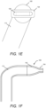
FIGs. 1E and 1F illustrate exemplary views of the nozzle/distributor fitted at an outlet of a supply tube of the heat exchanger in accordance with one or more embodiments of the disclosure. -
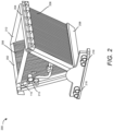
FIG. 2 is a schematic diagram illustrating an isometric view of a heat exchanger having a downward fluid flow configuration in accordance with one or more embodiments of the disclosure. -
FIG. 3 is an enlarged inner view ofFIG. 2 depicting the nozzle disposed within the inlet manifold of the heat exchanger ofFIG. 2 in accordance with one or more embodiments of the disclosure. - The following is a detailed description of embodiments of the disclosure depicted in the accompanying drawings. The embodiments are in such detail as to clearly communicate the disclosure. However, the amount of detail offered is not intended to limit the anticipated variations of embodiments; on the contrary, the intention is to cover all modifications, equivalents, and alternatives falling within the spirit and scope of the subject disclosure as defined by the appended claims.
- Various terms are used herein. To the extent a term used in a claim is not defined below, it should be given the broadest definition persons in the pertinent art have given that term as reflected in printed publications and issued patents at the time of filing.
- In the specification, reference may be made to the spatial relationships between various components and to the spatial orientation of various aspects of components as the devices are depicted in the attached drawings. However, as will be recognized by those skilled in the art after a complete reading of the subject disclosure, the components of this invention. described herein may be positioned in any desired orientation. Thus, the use of terms such as "above," "below," "upper," "lower," "first", "second" or other like terms to describe a spatial relationship between various components or to describe the spatial orientation of aspects of such components should be understood to describe a relative relationship between the components or a spatial orientation of aspects of such components, respectively, as the nozzle, multichannel tube, manifold, heat exchanger, and corresponding components, described herein may be oriented in any desired direction.
- Microchannel heat exchangers ("heat exchangers") typically include multiple microchannel tubes having multiple inlet ports, which connect and extend from an inlet manifold to an outlet manifold of the heat exchanger. The distribution of fluid among the multiple microchannel tubes plays a significant role in the overall performance of the heat exchanger and effective utilization of the heat transfer surface. This is also applicable to other categories of heat exchangers such as brazed plate heat exchangers, round tube plate fin heat exchangers, and the like. This distributor and heat exchanger described herein provide a simple and efficient distributor for the inlet manifold of heat exchangers, which enables even distribution of fluid or refrigerant across ports of the tubes within the inlet manifold of the heat exchanger with minimal pressure drop.
- Referring to
FIG. 1A to 1F , thedistributor 100 for an inlet manifold of a microchannel heat exchanger "heat exchanger" is disclosed. Thedistributor 100 is designed as anozzle 100 that is adapted to be fluidically connected to asupply tube 110 of a refrigeration line of the heat exchanger, where thesupply tube 110 is disposed within the inlet manifold through one of the ends of the inlet manifold. In some embodiments, thenozzle 100 may be removably fitted to an outlet of thesupply tube 110 within the inlet manifold, however, thenozzle 100 may also be an integral part of thesupply tube 110. - As illustrated in
FIGs. 1A to 1D , thenozzle 100 includes a firsthollow portion 102 having a round cross-section that is adapted to be fluidically connected to thesupply tube 110. Thenozzle 100 further includes a secondhollow portion 104 having an oval or elliptical cross-section, that is fluidically connected to thefirst portion 102 such that thenozzle 100 gradually transitions from thefirst portion 102 to thesecond portion 104 and the flow area of the nozzle reduces in a direction from thefirst portion 102 to thesecond portion 104. Thefirst portion 102 of thenozzle 100 has a predefined inner diameter equal to the inner diameter of thesupply tube 110. Thesecond portion 104 has a predefined height less than the inner diameter of thefirst portion 102 and a predefined width greater than the inner diameter of thefirst portion 102, thereby forming the oval or elliptical section. In an embodiment, thesecond portion 104 has a predefined width to height ratio ranging from 40 to 1/40, such that the flow area of the nozzle from thefirst portion 102 to thesecond portion 104 is reduced in a range of 20-70%. For instance, the width to height ratio of '40' corresponds to a flatsecond portion 104 in a horizontal orientation forming a wide nozzle. Further, the width to height ratio of ` 1' corresponds to a circular nozzle. Furthermore, the width to height ratio of ` 1/40' corresponds to a flat nozzle in vertical orientation. In addition, the major axis of the oval opening can be aligned to any other orientation in between horizontal and vertical axis. - Further, the
second portion 104 of thenozzle 100 is oriented at a predefined angle with respect to a horizontal plane of the inlet manifold. In an exemplary embodiment, as shown inFIG. 2 , the second portion (flat portion) 104 of thenozzle 100 can be oriented horizontally within theinlet manifold 202, however, the second portion (flat portion) 104 of the nozzle can also be oriented vertically or at another angle within theinlet manifold 202 based on design and orientation of theinlet manifold 202, and all such embodiments are well within the scope of this invention. - A first end of the nozzle (first portion 102) includes a
first opening 106 that is connected to thesupply tube 110 and a second end of the nozzle (second portion 104) includes asecond opening 108 opposite to thefirst opening 106. Thefirst opening 106 has a circular profile having a predefined inner diameter equal to the inner diameter of thesupply tube 110. Further, thesecond opening 108 has one or more of a race-track profile (e.g., elliptical), a rectangular profile, a circular profile, and an oval profile, but not limited to the like. In one or more embodiments, thenozzle 100 is fitted with thesupply tube 110 and is disposed within theinlet manifold 202 such that the second end orsecond opening 108 of thenozzle 100 remains before or in line with a first tube among the plurality oftubes 206 and thenozzle 100 remains at a predefined height above the first end (top end) of thetubes 206 of theheat exchanger 200 as shown inFIG. 3 . For instance, if the first tube is considered to be an origin along a longitudinal axis of the manifold 202, thesecond opening 108 of thenozzle 100 may remain at the origin or zero millimeters from the first tube. Further, thesecond opening 108 of thenozzle 100 may also be located at a desired distance before the first tube i.e., in a negative location from the first tube (origin) along the longitudinal axis of themanifold 202. - In some embodiments, the
nozzle 100 is fitted with thesupply tube 110 and is disposed within theinlet manifold 202 such that the second end orsecond opening 108 of thenozzle 100 can be located anywhere between two ends of the manifold 202 and at a predefined height above the top end of thetubes 206 of theheat exchanger 200. In such instance, thesecond opening 108 of thenozzle 100 may also be located after the first tube i.e., in a positive location from the first tube or origin along the longitudinal axis of themanifold 202. - In one or more embodiments, the length of the
nozzle 100 can be 0.3 to 2 times the diameter of theinlet manifold 202. As the flow area of thenozzle 100 reduces in a direction from thefirst portion 102 to thesecond portion 104 of thenozzle 100, the velocity of a fluid (refrigerant) increases while flowing through thenozzle 100, which helps in breaking the fluid into droplets much earlier, leading to homogeneous two-phase flow. In addition, the flat profile and horizontal orientation of thesecond portion 104 of thenozzle 100 generates a wider jet of the fluid within theinlet manifold 202 which nearly covers the entire diameter of theinlet manifold 202, thereby enhancing port to port distribution in thetubes 206 with minimal pressure drop. - In an embodiment, as shown in
FIGs. 1E and 1F , thesupply tube 110 may have an L-shaped profile with a first section extending upward within the inlet manifold from the bottom of the inlet manifold and a second section extending perpendicular to the first section with a curved section between the first section and the second section such that the second section of thesupply tube 110 remains parallel to a longitudinal axis of theinlet manifold 202. However, in other embodiments (not shown), thesupply tube 110 may be directly disposed within theinlet manifold 202 through a flat base at one of the ends of theinlet manifold 202 such that the supply tube remains parallel to a longitudinal axis of theinlet manifold 202. Further, thenozzle 100 is fitted at the outlet of the second section of thesupply tube 110 such that the vapor ejected by thenozzle 100 within theinlet manifold 202 nearly covers the entire diameter and length of theinlet manifold 202. - Referring to
FIGs. 2 and3 , an exemplary embodiment of theheat exchanger 200 of this invention having a downward fluid flow configuration is illustrated. Theheat exchanger 200 includes an inlet manifold 202 (also known as inlet header) and an outlet manifold 204 (also known as outlet header), which may preferably be configured horizontally over asupport structure 212 at the same elevation, however, in other embodiments, theinlet manifold 202 may also be positioned at an elevated height above theoutlet manifold 204. Further, theheat exchanger 200 includes a plurality of multichannel tubes 206 (tubes 206) in fluidic communication with theinlet manifold 202 and theoutlet manifold 204. Thetubes 206 are equally spaced and extend parallelly, with one end (first end) of thetube 206 disposed within theinlet manifold 202 and the other end extending out of theinlet manifold 202 at a predefined angle and further connected to and disposed within theoutlet manifold 204, however, thetubes 206 can also extend vertically downward from theinlet manifold 202 to enable flow of the fluid in the vertically downward direction. Further, in other embodiments (not shown inFIG. 2 ), thetubes 206 can also extend vertically upward or at an angle to a vertical axis from theinlet manifold 202 to enable flow of the fluid in the vertically upward direction. - The
tube 206 includes a hollow member which may preferably have a flat profile having opposite flat walls, however, thetube 206 may also have other profiles without any limitations and all such embodiments are well within the scope of this invention. Further,tube 206 includes multiple channels configured along an axis of the tube therewithin and extending parallelly between a first end (top end) and a second end (bottom end) of the hollow member such that multiple fluid flow paths of a predefined radius (for example, generally in the range of millimeters) are created between the first end and second end of the tube, which allows fluid such as refrigerant to flow from inlet ports of channels at the first end to the outlet ports of the channels at the second end of thetube 206. -
Tubes 206 are preferentially made of a lightweight, thermally conductive, and chemical-resistant material, however, thetube 206 may also be made of other materials as well, which are within the scope of this invention. In some embodiments,tube 206 may be made of aluminum extrusions. Thetubes 206 are shown in drawings hereof, for ease and clarity of illustration, as having a fixed number of channels defining flow paths having a square cross-section. However, it is to be understood that in commercial applications, such as for example refrigerant vapor compression systems, eachmultichannel tube 206 may typically have about ten to twenty flow channels, but may have a greater or a lesser multiplicity of channels, as desired. - The first end of the
tube 206 is adapted to be disposed within theinlet manifold 202 of theheat exchanger 200 using the brazing technique, 3-D printing technique, and other known techniques known in the art, such that thetube 206 remains inclined at a predefined angle from a horizontal planar axis of the manifold 202, with a certain section of the tube near the first end of the tube disposed within theinlet manifold 202 and rest section of thetube 100 protruding out of theinlet manifold 202 in the downward direction. Also,tube 206 is disposed within the manifold such that the flat wall or opposite walls of the tube orients perpendicular to a longitudinal axis of theinlet manifold 202 in the direction of the fluid coming out from the nozzle within themanifold 202. - The
manifolds manifolds tubes 206, such that a first end or a section of thetubes 206 remain within themanifolds tubes 206 are preferably formed of aluminum extrusions. Themanifolds tubes 206. The slots are punched in the sides of themanifolds manifolds - In an embodiment, a slot based on diameter of the
supply tube 110 is punched at one end of theinlet manifold 202 and thesupply tube 110 is inserted within theinlet manifold 202 followed by brazing thesupply tube 110 with theinlet manifold 202. Thenozzle 100 is fitted at the outlet of thesupply tube 110 within theinlet manifold 202 and the ends of theinlet manifold 202 are closed by caps using brazing or welding technique to provide a leak-proof design. Thesupply tube 110 fitted with thenozzle 100, is disposed within theinlet manifold 202 such that the second end orsecond opening 108 of thenozzle 100 remains at least partially before thetubes 206 and thenozzle 100 remains at a predefined height above the first end (top end) of thetubes 206. In another embodiment, thesupply tube 110 may also be attached or disposed within theinlet manifold 202 using 3-D printing techniques, and other known techniques known in the art. - Further, the
heat exchanger 200 includesheat dissipating fins 214 of brazed clad aluminum extending parallelly between adj acenttubes 206. Thefins 214 facilitate the exchange of heat between the fluid flowing through thetubes 206 and air flowing across thetubes 206 of theheat exchanger 200. Besides, thefins 214 also provide structural support and rigidity to thetubes 206 as well as theheat exchanger 200. - In some embodiments, as shown in
FIG. 2 , theheat exchanger 200 is a V-coilarrangement heat exchanger 200 having theinlet manifold 202 and theoutlet manifold 204 oriented horizontally in the same plane over thesupport structure 212. Further,tubes 206 protrude from theinlet manifold 202 making an acute angle from the plane of theinlet manifold 202 in a downward direction and further extending in an upward direction at the same acute angle into theoutlet manifold 204, such that the V-coil arrangement of thetubes 206 having a bend at bottom mid-point of thetubes 206 is formed. The bend at the bottom oftubes 206 results in the formation of an apex at the approximate midpoint of the V-shapedtubes 206. The apex is below the plane defined by the manifolds. Further, acondensate trough 208 is attached along the apex or bend of thetubes 206 by fasteners, extending along an axis parallel to the longitudinal axis of themanifolds Trough 208 is configured to collect condensate formed in thetubes 206 and the V-coil arrangement facilitates an easier flow of condensate towards thebottom trough 208. Thetrough 208 may be further provided with one or morecondensate outlet fittings 216 to remove the collected condensate. - During operation,
heat exchanger 200 receives cold two-phase mixture from the expansion device through a refrigerant line into theinlet manifold 202 of theheat exchanger 200 via thesupply tube 110 and the distributor/nozzle 100. As the flow area of thenozzle 100 reduces in a direction from thefirst portion 102 to thesecond portion 104 of thenozzle 100, the velocity of mixture increases while flowing through thenozzle 100, which helps in breaking the liquid jet or jets into droplets much earlier leading to homogeneous two-phase flow and good distribution. In addition, the flat profile of thesecond portion 104 of thenozzle 100 generates a wider jet of the vapor within theinlet manifold 202 which nearly covers the entire diameter of theinlet manifold 202, thereby enhancing port-to-port distribution in thetubes 206. This increases the thermal capacity of theheat exchanger 200 compared to existing heat exchangers. - Further, the cold two-phase mixture within the
inlet manifold 202 passes through thetubes 206 of theheat exchanger 200 where the two-phase mixture gets heated as it passes in a heat exchange relationship with an ambient air which is passed over the by a fan (not shown) that may be configured over top of theheat exchanger 200. The superheated vapor collects in theoutlet manifold 204 ofheat exchanger 200 and goes to the compressor and the cycle is completed. Further, the condensate from the condenser comes and expands to a low-pressure two-phase mixture in anexpansion device 210. - It should be obvious to a person skilled in the art that while
FIG, 2 and some embodiments of this invention have been elaborated for the V-coil arrangement heat exchanger for the sake of simplicity and better explanation purpose, however, the teachings of this invention are equally applicable for other heat exchanger having downward fluid flow configuration such as N-coil heat exchanger, J-coil heat exchanger, U-coil heat exchanger, and the like, and all such embodiments are well within the scope of this invention. - Thus, this invention (nozzle or distributor) overcomes the drawbacks, limitations, and shortcomings associated with existing technologies by providing a simple and efficient nozzle that enables even distribution of fluid or refrigerant across ports of the tubes within the inlet manifold of heat exchanger, with minimal pressure drop.
- While the invention has been described with reference to exemplary embodiments, it will be understood by those skilled in the art that various changes may be made and equivalents may be substituted for elements thereof without departing from the scope of the invention as defined by the appended claims. Modifications may be made to adopt a particular situation or material to the teachings of the invention without departing from the scope thereof. Therefore, it is intended that the invention not be limited to the particular embodiment disclosed, but that the invention includes all embodiments falling within the scope of the invention as defined by the appended claims.
- In interpreting the specification, all terms should be interpreted in the broadest possible manner consistent with the context. In particular, the terms "comprises" and "comprising" should be interpreted as referring to elements, components, or steps in a non-exclusive manner, indicating that the referenced elements, components, or steps may be present, or utilized, or combined with other elements, components, or steps that are not expressly referenced. Where the specification claims refer to at least one of something selected from the group consisting of A, B, C ....and N, the text should be interpreted as requiring only one element from the group, not A plus N, or B plus N, etc.
- The following clauses set out features of the invention which may or may not presently be claimed in this application, but which may form the basis for future amendment or a divisional application.
- 1. A distributor for an inlet manifold of a microchannel heat exchanger, the distributor comprising:
- a nozzle adapted to the fluidically connected to a supply tube of a refrigeration line of the heat exchanger, wherein the supply tube is at least partially disposed within an inlet manifold of the heat exchanger,
- the nozzle comprising:
- a first hollow portion having a round cross-section and adapted to be fluidically connected to the supply tube; and
- a second hollow portion having an oval or elliptical cross-section, wherein the second portion is fluidically connected to the first portion such that the nozzle gradually transitions from the first portion to the second portion and flow area of the nozzle reduces in a direction from the first portion to the second portion.
- 2. The distributor of clause 1, wherein a first end of the nozzle comprises a first opening that is connected to the supply tube and a second end of the nozzle comprises a second opening opposite to the first opening.
- 3. The distributor of clause 2, wherein the second opening has one or more of a race-track profile, a rectangular profile, a circular profile, and an oval profile.
- 4. The distributor of clause 2, wherein the nozzle is disposed within the inlet manifold such that the second end or second opening of the nozzle remains at least partially before one or more microchannel tubes associated with the inlet manifold.
- 5. The distributor of clause 1, wherein the nozzle is at a predefined height above ports associated with one or more microchannel tubes associated with the inlet manifold.
- 6. The distributor of clause 1, wherein the first portion of the nozzle has a predefined inner diameter equal to an inner diameter of the supply tube, and wherein the second portion has a predefined height less than the inner diameter of the first portion and a predefined width greater than the inner diameter of the first portion.
- 7. The distributor of clause 1, wherein the second portion has a predefined width to height ratio ranging from 40 to 1/40.
- 8. The distributor of clause 1, wherein the second portion is oriented at a predefined angle within respect to a horizontal plane of the inlet manifold.
- 9. The distributor of clause 1, wherein the second portion is oriented horizontally within the inlet manifold.
- 10. The distributor of clause 1, wherein the flow area of the nozzle from the first portion to the second portion is reduced in a range of 20-70%.
- 11. A heat exchanger comprising:
- an inlet manifold fluidically connected to an outlet manifold via a plurality of microchannel tubes;
- a supply tube associated with a refrigeration line at least partially disposed within the inlet manifold; and
- a nozzle fluidically connected to the supply tube within the inlet manifold, the nozzle comprising:
- a first hollow portion having a round cross-section and adapted to be fluidically connected to the supply tube; and
- a second hollow portion having an oval or elliptical cross-section,
- wherein the second portion is fluidically connected to the first portion such that the nozzle gradually transitions from the first portion to the second portion and flow area of the nozzle reduces in a direction from the first portion to the second portion.
- 12. The heat exchanger of clause 11, wherein a first end of the nozzle comprises a first opening that is connected to the supply tube and a second end of the nozzle comprises a second opening opposite to the first opening.
- 13. The heat exchanger of clause 12, wherein the second opening has one or more of a race-track profile, a rectangular profile, a circular profile, and an oval profile.
- 14. The heat exchanger of clause 12, wherein the nozzle is disposed within the inlet manifold such that the second opening of the nozzle remains at least partially before the microchannel tubes within the inlet manifold.
- 15. The heat exchanger of clause 11, wherein the nozzle is at a predefined height above ports associated with the microchannel tubes withing the inlet manifold.
- 16. The heat exchanger of clause 11, wherein the first portion of the nozzle has a predefined inner diameter equal to an inner diameter of the supply tube, and wherein the second portion has a predefined height less than the inner diameter of the first portion and a predefined width greater than the inner diameter of the first portion.
- 17. The distributor of clause 11, wherein the second portion has a predefined width to height ratio ranging from 40 to 1/40.
- 18. The heat exchanger of clause 11, wherein the second portion is oriented at a predefined angle within respect to a horizontal plane of the inlet manifold.
- 19. The heat exchanger of clause 11, wherein the flow area of the nozzle from the first portion to the second portion is reduced in a range of 20-70%.
- 20. The heat exchanger of clause 11, wherein the supply tube is disposed of at one end of the inlet manifold, and wherein the supply tube is configured to supply a fluid from the refrigeration line within the inlet manifold via the nozzle to enable uniform distribution of the fluid across ports of each of the multichannel tubes within the inlet manifold.
Claims (12)
- A distributor (100) for an inlet manifold of a microchannel heat exchanger, the distributor comprising:a nozzle (100) adapted to the fluidically connected to a supply tube (110) of a refrigeration line of the heat exchanger, wherein the supply tube (110) is at least partially disposed within an inlet manifold (202) of the heat exchanger,the nozzle (100) comprising:a first hollow portion (102) having a round cross-section and adapted to be fluidically connected to the supply tube; anda second hollow portion (104) having an oval or elliptical cross-section, wherein the second portion (104) is fluidically connected to the first portion (102) such that the nozzle (100) gradually transitions from the first portion (102) to the second portion (104) and a flow area of the nozzle reduces in a direction from the first portion to the second portion.
- The distributor of claim 1, wherein a first end (102) of the nozzle comprises a first opening (106) that is connected to the supply tube and a second end (104) of the nozzle comprises a second opening (108) opposite to the first opening (106).
- The distributor of claim 2, wherein the second opening (108) has one or more of a race-track profile, a rectangular profile, a circular profile, and an oval profile.
- The distributor of claim 2 or 3, wherein the nozzle (100) is disposed within the inlet manifold such that the second end (104) or second opening (108) of the nozzle (100) remains at least partially before one or more microchannel tubes (206) associated with the inlet manifold (202).
- The distributor of any preceding claim, wherein the nozzle (100) is at a predefined height above ports associated with one or more microchannel tubes (206) associated with the inlet manifold (202).
- The distributor of any preceding claim, wherein the first portion (102) of the nozzle (100) has a predefined inner diameter equal to an inner diameter of the supply tube (110), and wherein the second portion has a predefined height less than the inner diameter of the first portion (104) and a predefined width greater than the inner diameter of the first portion (102).
- The distributor of any preceding claim, wherein the second portion (104) has a predefined width to height ratio ranging from 40 to 1/40.
- The distributor of any preceding claim, wherein the second portion (104) is oriented at a predefined angle within respect to a horizontal plane of the inlet manifold (202).
- The distributor of any preceding claim, wherein the second portion (104) is oriented horizontally within the inlet manifold (202).
- The distributor of any preceding claim, wherein the flow area of the nozzle (100) from the first portion (102) to the second portion (104)is reduced in a range of 20-70%.
- A heat exchanger comprising:an inlet manifold (202) fluidically connected to an outlet manifold (204) via a plurality of microchannel tubes (206);a supply tube (110) associated with a refrigeration line at least partially disposed within the inlet manifold (202); anda distributor (100) as claimed in any preceding claim.
- The heat exchanger of claim 11, wherein the supply tube (110) is disposed of at one end of the inlet manifold (202), and wherein the supply tube (110) is configured to supply a fluid from the refrigeration line within the inlet manifold (202) via the nozzle (100) to enable uniform distribution of the fluid across ports of each of the multichannel tubes (206) within the inlet manifold (202).
Applications Claiming Priority (1)
| Application Number | Priority Date | Filing Date | Title |
|---|---|---|---|
| US202263477114P | 2022-12-23 | 2022-12-23 |
Publications (2)
| Publication Number | Publication Date |
|---|---|
| EP4400795A1 true EP4400795A1 (en) | 2024-07-17 |
| EP4400795B1 EP4400795B1 (en) | 2026-05-06 |
Family
ID=89224297
Family Applications (1)
| Application Number | Title | Priority Date | Filing Date |
|---|---|---|---|
| EP23218306.1A Active EP4400795B1 (en) | 2022-12-23 | 2023-12-19 | Simple distributor for inlet manifold of microchannel heat exchanger |
Country Status (3)
| Country | Link |
|---|---|
| US (1) | US12566035B2 (en) |
| EP (1) | EP4400795B1 (en) |
| CN (1) | CN118242924A (en) |
Citations (3)
| Publication number | Priority date | Publication date | Assignee | Title |
|---|---|---|---|---|
| US20100242535A1 (en) * | 2009-03-25 | 2010-09-30 | Jiang Jianlong | Refrigerant distributor for heat exchanger and heat exchanger |
| US20130192808A1 (en) * | 2010-09-13 | 2013-08-01 | Danfoss A/S | Refrigerant guiding pipe and heat exchanger having refrigerant guiding pipe |
| US9423190B2 (en) * | 2009-04-03 | 2016-08-23 | Sanhua (Hangzhou) Micro Channel Heat Exchanger Co. | Refrigerant distributor for heat exchanger and heat exchanger |
Family Cites Families (23)
| Publication number | Priority date | Publication date | Assignee | Title |
|---|---|---|---|---|
| JPH0717965Y2 (en) * | 1990-02-22 | 1995-04-26 | サンデン株式会社 | Heat exchanger |
| DE4422178A1 (en) | 1993-07-03 | 1995-01-12 | Flitsch E Gmbh & Co | Device for distributing coolant in an evaporator |
| US5415223A (en) | 1993-08-02 | 1995-05-16 | Calsonic International, Inc. | Evaporator with an interchangeable baffling system |
| JPH07301472A (en) | 1994-05-09 | 1995-11-14 | Matsushita Refrig Co Ltd | Header |
| US5479784A (en) | 1994-05-09 | 1996-01-02 | Carrier Corporation | Refrigerant distribution device |
| JP3007839B2 (en) | 1996-03-13 | 2000-02-07 | 松下冷機株式会社 | Shunt |
| JP3705859B2 (en) * | 1996-03-29 | 2005-10-12 | サンデン株式会社 | Heat exchanger with distribution device |
| DE19719251C2 (en) | 1997-05-07 | 2002-09-26 | Valeo Klimatech Gmbh & Co Kg | Distribution / collection box of an at least double-flow evaporator of a motor vehicle air conditioning system |
| US6145587A (en) * | 1997-09-24 | 2000-11-14 | Showa Aluminum Corporation | Evaporator |
| FR2769974B1 (en) * | 1997-10-20 | 2000-01-07 | Valeo Climatisation | EVAPORATOR WITH IMPROVED HEAT EXCHANGE CAPACITY |
| US6363965B1 (en) | 1998-08-25 | 2002-04-02 | Eaton Aeroquip Inc. | Manifold assembly |
| FR2826438B1 (en) * | 2001-06-20 | 2004-01-23 | Valeo Climatisation | ARRANGEMENT OF INPUT AND OUTPUT TUBES FOR AN EVAPORATOR |
| FR2826439B1 (en) * | 2001-06-26 | 2003-10-03 | Valeo Climatisation | HEAT EXCHANGER, PARTICULARLY EVAPORATOR, WITH IMPROVED PERFERMANCE |
| JP4213496B2 (en) * | 2003-03-26 | 2009-01-21 | カルソニックカンセイ株式会社 | Heat exchanger |
| ES2363784T3 (en) | 2005-02-02 | 2011-08-16 | Carrier Corporation | MINICANAL COLLECTOR FOR HEAT EXCHANGER. |
| WO2006083426A1 (en) | 2005-02-02 | 2006-08-10 | Carrier Corporation | Tube inset and bi-flow arrangement for a header of a heat pump |
| US7967060B2 (en) | 2005-08-18 | 2011-06-28 | Parker-Hannifin Corporation | Evaporating heat exchanger |
| WO2008064219A1 (en) | 2006-11-22 | 2008-05-29 | Johnson Controls Technology Company | Multichannel evaporator with flow mixing manifold |
| US7921558B2 (en) | 2008-01-09 | 2011-04-12 | Delphi Technologies, Inc. | Non-cylindrical refrigerant conduit and method of making same |
| CN107543336A (en) | 2016-06-23 | 2018-01-05 | 杭州三花家电热管理系统有限公司 | Header and the heat exchanger with the header |
| JP7071678B2 (en) * | 2018-09-28 | 2022-05-19 | ダイキン工業株式会社 | Heat exchanger |
| JP7214042B1 (en) * | 2021-04-06 | 2023-01-27 | 三菱電機株式会社 | heat exchangers and air conditioners |
| CN215984075U (en) | 2021-08-20 | 2022-03-08 | 浙江盾安热工科技有限公司 | Micro-channel heat exchanger and air conditioning system with same |
-
2023
- 2023-12-19 EP EP23218306.1A patent/EP4400795B1/en active Active
- 2023-12-19 US US18/389,675 patent/US12566035B2/en active Active
- 2023-12-21 CN CN202311768528.9A patent/CN118242924A/en active Pending
Patent Citations (3)
| Publication number | Priority date | Publication date | Assignee | Title |
|---|---|---|---|---|
| US20100242535A1 (en) * | 2009-03-25 | 2010-09-30 | Jiang Jianlong | Refrigerant distributor for heat exchanger and heat exchanger |
| US9423190B2 (en) * | 2009-04-03 | 2016-08-23 | Sanhua (Hangzhou) Micro Channel Heat Exchanger Co. | Refrigerant distributor for heat exchanger and heat exchanger |
| US20130192808A1 (en) * | 2010-09-13 | 2013-08-01 | Danfoss A/S | Refrigerant guiding pipe and heat exchanger having refrigerant guiding pipe |
Also Published As
| Publication number | Publication date |
|---|---|
| CN118242924A (en) | 2024-06-25 |
| US20240210128A1 (en) | 2024-06-27 |
| EP4400795B1 (en) | 2026-05-06 |
| US12566035B2 (en) | 2026-03-03 |
Similar Documents
| Publication | Publication Date | Title |
|---|---|---|
| US4966230A (en) | Serpentine fin, round tube heat exchanger | |
| US5341870A (en) | Evaporator or evaporator/condenser | |
| US10048020B2 (en) | Heat transfer surfaces with flanged apertures | |
| US6220340B1 (en) | Heat exchanger with dimpled bypass channel | |
| EP0559983A1 (en) | Evaporator or evaporator/condenser | |
| JP2004144460A (en) | Heat exchanger | |
| CN101490494A (en) | Spiral flat-tube heat exchanger | |
| KR20010007153A (en) | Refrigerant evaporator | |
| CN103238038B (en) | Microchannel Heat Exchanger Fins | |
| JP3911604B2 (en) | Heat exchanger and refrigeration cycle | |
| CN110595250B (en) | Heat Exchanger | |
| EP4400795B1 (en) | Simple distributor for inlet manifold of microchannel heat exchanger | |
| CN107709915A (en) | Miniature pipe in pipe | |
| US20080184734A1 (en) | Flat Tube Single Serpentine Co2 Heat Exchanger | |
| US12523434B2 (en) | Refrigerant distribution and charge balancing system for heat exchangers | |
| JPH0755380A (en) | Heat exchanger | |
| US12250795B2 (en) | Systems for a heat exchanger | |
| US20240210077A1 (en) | Microchannel tube for evaporators | |
| EP4481305A1 (en) | Flexible and adjustable compensator for microchannel indoor units | |
| US20250155199A1 (en) | Microchannel Heat Exchanger | |
| WO2008025131A1 (en) | Heat transfer surfaces with flanged apertures | |
| US20250283673A1 (en) | Laminated header for a microchannel heat exchanger | |
| JP2005016866A (en) | Heat exchanger | |
| EP4589238A1 (en) | A fluid distributor for a heat exchanger | |
| EP4545899A1 (en) | MICROCHANNEL HEAT EXCHANGER |
Legal Events
| Date | Code | Title | Description |
|---|---|---|---|
| PUAI | Public reference made under article 153(3) epc to a published international application that has entered the european phase |
Free format text: ORIGINAL CODE: 0009012 |
|
| STAA | Information on the status of an ep patent application or granted ep patent |
Free format text: STATUS: THE APPLICATION HAS BEEN PUBLISHED |
|
| AK | Designated contracting states |
Kind code of ref document: A1 Designated state(s): AL AT BE BG CH CY CZ DE DK EE ES FI FR GB GR HR HU IE IS IT LI LT LU LV MC ME MK MT NL NO PL PT RO RS SE SI SK SM TR |
|
| STAA | Information on the status of an ep patent application or granted ep patent |
Free format text: STATUS: REQUEST FOR EXAMINATION WAS MADE |
|
| 17P | Request for examination filed |
Effective date: 20250108 |
|
| GRAP | Despatch of communication of intention to grant a patent |
Free format text: ORIGINAL CODE: EPIDOSNIGR1 |
|
| STAA | Information on the status of an ep patent application or granted ep patent |
Free format text: STATUS: GRANT OF PATENT IS INTENDED |
|
| INTG | Intention to grant announced |
Effective date: 20250723 |
|
| GRAS | Grant fee paid |
Free format text: ORIGINAL CODE: EPIDOSNIGR3 |
|
| GRAA | (expected) grant |
Free format text: ORIGINAL CODE: 0009210 |
|
| STAA | Information on the status of an ep patent application or granted ep patent |
Free format text: STATUS: THE PATENT HAS BEEN GRANTED |
|
| AK | Designated contracting states |
Kind code of ref document: B1 Designated state(s): AL AT BE BG CH CY CZ DE DK EE ES FI FR GB GR HR HU IE IS IT LI LT LU LV MC ME MK MT NL NO PL PT RO RS SE SI SK SM TR |
|
| REG | Reference to a national code |
Ref country code: CH Ref legal event code: F10 Free format text: ST27 STATUS EVENT CODE: U-0-0-F10-F00 (AS PROVIDED BY THE NATIONAL OFFICE) Effective date: 20260506 Ref country code: GB Ref legal event code: FG4D |